US5243994A - Instrument for tissue sampling including a carriage assembly - Google Patents
Instrument for tissue sampling including a carriage assemblyDownload PDFInfo
- Publication number
- US5243994A US5243994AUS07/834,622US83462292AUS5243994AUS 5243994 AUS5243994 AUS 5243994AUS 83462292 AUS83462292 AUS 83462292AUS 5243994 AUS5243994 AUS 5243994A
- Authority
- US
- United States
- Prior art keywords
- carriage
- stylet
- cannula
- structures
- drive
- Prior art date
- Legal status (The legal status is an assumption and is not a legal conclusion. Google has not performed a legal analysis and makes no representation as to the accuracy of the status listed.)
- Expired - Lifetime
Links
- 238000005070samplingMethods0.000titleclaimsabstractdescription29
- 238000006073displacement reactionMethods0.000claimsabstractdescription31
- 238000009434installationMethods0.000claimsabstractdescription6
- 230000008878couplingEffects0.000claimsdescription18
- 238000010168coupling processMethods0.000claimsdescription18
- 238000005859coupling reactionMethods0.000claimsdescription18
- 230000033001locomotionEffects0.000abstractdescription29
- 210000001519tissueAnatomy0.000description47
- 239000000523sampleSubstances0.000description20
- 210000002307prostateAnatomy0.000description6
- 230000006835compressionEffects0.000description4
- 238000007906compressionMethods0.000description4
- 238000000034methodMethods0.000description4
- 230000000712assemblyEffects0.000description3
- 238000000429assemblyMethods0.000description3
- 230000007246mechanismEffects0.000description3
- 230000035515penetrationEffects0.000description3
- 230000004913activationEffects0.000description2
- 238000013459approachMethods0.000description2
- 238000001574biopsyMethods0.000description2
- 210000001124body fluidAnatomy0.000description2
- 239000010839body fluidSubstances0.000description2
- 230000000881depressing effectEffects0.000description2
- 238000012986modificationMethods0.000description2
- 230000004048modificationEffects0.000description2
- 230000003252repetitive effectEffects0.000description2
- 230000000717retained effectEffects0.000description2
- 238000000926separation methodMethods0.000description2
- 238000002604ultrasonographyMethods0.000description2
- 208000012287ProlapseDiseases0.000description1
- 230000009471actionEffects0.000description1
- 210000000436anusAnatomy0.000description1
- 230000009286beneficial effectEffects0.000description1
- 238000003745diagnosisMethods0.000description1
- 230000009977dual effectEffects0.000description1
- 210000003811fingerAnatomy0.000description1
- 239000012530fluidSubstances0.000description1
- 210000005224forefingerAnatomy0.000description1
- 210000004907glandAnatomy0.000description1
- 230000000977initiatory effectEffects0.000description1
- 210000000056organAnatomy0.000description1
- 238000002360preparation methodMethods0.000description1
- 239000011347resinSubstances0.000description1
- 229920005989resinPolymers0.000description1
- 230000002441reversible effectEffects0.000description1
- 210000001550testisAnatomy0.000description1
Images


Classifications
- A—HUMAN NECESSITIES
- A61—MEDICAL OR VETERINARY SCIENCE; HYGIENE
- A61B—DIAGNOSIS; SURGERY; IDENTIFICATION
- A61B10/00—Instruments for taking body samples for diagnostic purposes; Other methods or instruments for diagnosis, e.g. for vaccination diagnosis, sex determination or ovulation-period determination; Throat striking implements
- A61B10/02—Instruments for taking cell samples or for biopsy
- A61B10/0233—Pointed or sharp biopsy instruments
- A61B10/0241—Pointed or sharp biopsy instruments for prostate
- A—HUMAN NECESSITIES
- A61—MEDICAL OR VETERINARY SCIENCE; HYGIENE
- A61B—DIAGNOSIS; SURGERY; IDENTIFICATION
- A61B17/00—Surgical instruments, devices or methods
- A61B17/00234—Surgical instruments, devices or methods for minimally invasive surgery
- A61B2017/00238—Type of minimally invasive operation
- A61B2017/00274—Prostate operation, e.g. prostatectomy, turp, bhp treatment
- A—HUMAN NECESSITIES
- A61—MEDICAL OR VETERINARY SCIENCE; HYGIENE
- A61B—DIAGNOSIS; SURGERY; IDENTIFICATION
- A61B18/00—Surgical instruments, devices or methods for transferring non-mechanical forms of energy to or from the body
- A61B2018/00315—Surgical instruments, devices or methods for transferring non-mechanical forms of energy to or from the body for treatment of particular body parts
- A61B2018/00547—Prostate
Definitions
- the present inventionrelates to instruments for obtaining tissue samples to be used for example in biopsy procedures. More particularly, the invention relates to improved instruments for propelling needle assemblies to sample the diagnostic tissue.
- needle assemblieswhich capture a longitudinal, or core sample of the tissue which is extracted for diagnosis.
- the needle assemblyhas a hollow outer cannula needle through which a cutting, stylet needle is slidably projected to cut and capture a core of the tissue within a notch formed in the inner stylet as described for example in U.S. Pat. No. 4,776,346.
- the sampling procedure for such a needle assemblyrequires separate motions of the inner stylet and the outer cannula to accomplish the tissue capture.
- the instrument described in the aforementioned patentallows a physician to manually perform the dual motions of the needle assembly, however, each motion requires a separate and different manual activation.
- a tissue sampling instrumentfor use with a two-part needle assembly having an outer cannula and an inner stylet, includes first and second carriage structures for displacing the respective stylet and cannula.
- the instrumentalso includes a drive carriage structure which provides separate and sequential engagement and displacement of the two needle carriage structures during operation of the instrument.
- the drive carriage structurefirst engages and displaces the stylet carriage, and thereafter engages and displaces the cannula carriage in order to produce sequential motions of the stylet and cannula in the operation to capture the tissue sample.
- the drive carriage structurealso includes means for releasing the engagement of the stylet carriage at the termination of its driven displacement prior to the sequentially successive engagement of the cannula carriage structure.
- the stylet and cannula carriage structures of the two-part needle assemblyare coupled to enable positively and releasably retaining the two carriage structures together prior to installation of the coupled needle assembly into the instrument housing the drive carriage structure.
- the preferred drive carriage structureincludes a deflectable arm structure which engages and drives the first, stylet carriage and then disengages the stylet carriage during the driven displacement of the cannula carriage.
- the instrument housingprovides guide grooves for the displacement of the carriage structures and the deflectable arm structure which will allow variable lengths of stroke for the needle, for example a 25 or 13 mm stroke.
- the drive carriageis propelled by a single drive spring which is expanded and compressed with reversible motions of the drive carriage.
- a manually slidable cocking memberis provided not only to compress the drive spring and slide the drive carriage into position for operating the instrument, but in addition, the cocking member serves as a releasable guard to selectively prevent inadvertent operation of a trigger member which releases the spring compression and drive carriage to initiate the tissue sampling operation. That is to say the device can only be operated when the guard or cocking member has been properly withdrawn from the trigger member.
- a particularly preferred embodiment of the tissue sampling instrumentalso includes a counting/disabling mechanism for repeated tissue sampling operations of the instrument.
- the counting/disabling mechanismcan also be employed to limit the number of successive tissue sampling operations of the instrument, particularly by preventing cocking or full compression of the drive spring after a pre-selected, repetitive sampling operation limit has been reached.
- FIG. 1is a perspective view of one embodiment of the tissue sampling in accordance with the present invention.
- FIG. 2is a perspective view of the instrument in FIG. 1 and illustrating a needle assembly removed from the housing of the instrument;
- FIG. 3is an exploded perspective view of the needle assembly and instrument housing of FIGS. 1 and 2;
- FIG. 4is a bottom plan view of the carriages in the needle assembly shown in FIGS. 2 and 3
- FIGS. 5, 6 and 7are diagrammatic views illustrating the tissue and tissue sampling operation of the needle assembly and instrument of FIGS. 1-4;
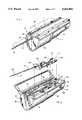
- FIG. 8is a sectional view of the instrument of FIGS. 2 and 3 showing the needle assembly removed from the housing of the instrument;
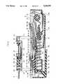
- FIG. 9is a sectional view of the instrument of FIGS. 1-3 and corresponding to the beginning of the tissue sampling operation shown in FIG. 5;
- FIG. 10is a sectional view of the instrument similar to FIG. 9 showing an intermediate stage in the tissue sampling operation of the instrument generally corresponding to FIG. 6;
- FIG. 11is a sectional view of the instrument similar to FIGS. 9 and 10 and showing the instrument at the completion of the tissue sampling operation generally corresponding to FIG. 7.
- the instrument 10includes a housing 12 which has a hinged cover 14 that opens to enable installation and removal of a needle assembly generally designated by reference character 16.
- the cover 14has a shallow channel 14a to accommodate an ultrasound probing instrument, shown in dotted outline, for aiding in location of the tissue to be sampled.
- the probe portion of the instrumentwill be disposed closely adjacent the needle assembly 16 due to the groove 14a.
- a bevelled upper edge 12a of the housing 12 at the free edge of the cover 14facilitates manual access for opening the cover 14.
- the needle assembly 16includes an outer cannula 18 through which a stylet 20 is slidably projected to cut and capture a core of the diagnostic tissue, as more fully described hereinafter.
- the rear end 20a of the stylet 20is secured within a stylet hub or carriage 22 and the rear end 18a of the cannula 18 is secured within a cannula hub or carriage 24. As best shown in FIGS.
- the carriages 22 and 24are coupled to enable limited relative sliding and displacement of the carriages, and the carriages can be uncoupled to allow the stylet 20 to be entirely withdrawn from the cannula 18 in order to enable the tissue core sample to be removed from the notch 20b in the stylet 20, and also to permit a syringe to be attached to the cannula carriage for obtaining a body fluid sample.
- the needle assembly 16is vertically lowered or disposed into the opened housing 12 so that the stylet 20 and cannula 18 are laid into and project from a notch 26 formed in the front wall 28 of the housing 12.
- the housing 12has opposing side walls 30 and 32 molded as generally vertically split housing halves. The sides 30 and 32 are joined to provide an upper wall 34 which has a large, elongate aperture 36 through which the needle assembly 16 is installed and then removed as shown in FIGS. 2 and 8.
- FIGS. 5-7illustrate representative operating steps and displacements of the stylet 20 and cannula 18, carried on the respective carriages 22 and 24, to obtain a tissue sample core from a prostate gland A.
- the stylet notch 20bis covered by the cannula 18 and the sharp, incising stylet end 20c may slightly project from the sharp end 18c of the cannula.
- the physicianholds the instrument 10 and guides the stylet 20 and cannula 18 into the peritoneal area between the anus and testicles until the stylet end 20c closely approaches (or slightly penetrates) the prostate gland A preferably with the locating aid of, for example, an ultrasound probe, shown in dotted outline in FIG. 1.
- the tissue core sampling operationis activated by first driving the displacement of the stylet alone into the prostate gland to a depth at which the prostate tissue prolapses into the stylet notch 20b, as shown in FIG. 6. Thereafter, as shown in FIG. 7, while the stylet 20 remains stationary, the cannula 18 is driven forward telescoping over the stylet 20 so that the sharp cannula end 18c cuts through the tissue and slices the top of the prolapsed tissue portion A' within the specimen notch 20b resulting in the capture of the prolapsed tissue as a longitudinal core sample.
- the tissue sample A'is retained in the sample notch 20b when the stylet 20 is retracted rearwardly through the cannula 18 and withdrawn therefrom in order to remove the core sample from the notch 20b for the tissue analysis.
- the cannula 18remains in place upon removal of the stylet in preparation for a further tissue sampling.
- the stylet 20 and cannula 18can be removed as a unit, if desired.
- the separate stylet and cannula motions of the sampling operationrequire that the stylet carriage 22 move forward and then stop the displacement of the stylet 20 prior to initiation of the forward motion of the cannula carriage 24, as more fully described hereinafter.
- the carriages 22 and 24 of the needle assembly 16are guided in their operating displacements by respectively paired guide slots or grooves 38, 38 and 40, 40 which are molded into the housing sides 30 and 32 and located just below opening 36 through the upper wall 34.
- the guide slots 38 and 40have respective vertical passageways 38a and 40a and entrance bosses 38b and 40b which align passage of respective bearing pins 22a and 24a formed on the carriages 22 and 24, through the upper wall 34 during the installation of the needle assembly 16.
- the bearing pins 22a and 24aare supported by and guided within the respective guide grooves 38 and 40 during the operating displacements of the respective carriages 22 and 24 as more fully described hereinafter.
- FIG. 8is shown with carriages 22 and 24 removed for viewing clarity.
- the drive means 41is comprised primarily of the drive member or structure 42 and the drive trailer or follower 52, which is pivotally attached to the drive member 42.
- the drive structure 42has a pair of laterally extending bearing flanges 42a shown in FIG. 3 which are supported and reversibly slide in a pair of opposing, main drive structure guide grooves 44 molded into the housing sides 30 and 32 below the grooves 38 and 40.
- the drive structure 42includes a blind cavity 46 which opens to the rear of the structure 42 and in which a helical drive spring 48 is disposed and horizontally projects in the expanded condition of the spring. One end 48a of the spring is secured at the inner end of the cavity 46 and the opposite end of the spring is secured on a stationary anchor member 50, see FIG. 8.
- a drive trailer or follower structuregenerally designated by reference character 52 is pivotably coupled to the drive structure 42.
- the forward portion of the trailer structureis formed by a pair of spaced trailer arms 52a each having an inwardly extending coupling pin 52b which is pivotally received within a respective coupling mortise 42a formed in the opposite sides of the drive carriage 42.
- the rear end of the trailer structure 52has a bridge portion 52c which joins the arms 52a and also has a pair of spaced, upstanding drive pins 52d which, as will be detailed hereinafter, engage and drive rear surfaces formed on respective shoulders 22b laterally extending from the upper portion of the stylet carriage 22, during its operating displacement.
- each of the drive pins 52dis a laterally extending cam following pin 52e which is displaced and guided within a respective cam guide groove 54 molded into each of the respective housing sides 30 and 32 between each of the respective drive member guide grooves 44 and the respective grooves 38.
- the cam guide groove 54has a forward generally horizontal portion 54b and a rearward, inclined portion 54a, for a purpose to be explained.
- the tissue sampling and instrument operationbegins with "cocking" the drive member 42 by manually retracting the reversibly slidable cocking member 56 on the outside of the housing 12.
- the cocking memberhas inwardly projecting guide flanges 56a which ride in guide grooves 58 formed in the exterior of the respective housing halves 30 and 32 as shown in FIG. 3.
- the cocking member 56also has an inwardly projecting drive tongue 56b which engages the front surface of the drive member 42 in order to rearwardly displace the drive member 42 to its power position and thereby compress the helical drive spring 48.
- the compressed spring 48is then disposed within cavity 46 when the cocking member 56 is manually retracted from the sectioned, solid line position on the left in FIG.
- a trigger guard portion 33extends from the bottom rear of each of the respective housing sides 30, 32 to flank and conceal the lever arm portion 58b of the trigger except at the free end which is exposed for the deliberate elevation by the physician's finger C.
- the trailer guide pins 52eare guided upwardly by the inclined groove portion 54b and lift the drive pins 52d into position for engagement with the rear surface of the carriage shoulders 22b on the stylet carriage 22 which is thereafter installed with the coupled cannula carriage 24 into the previously cocked, power position of the drive carriage 42 and trailer member 52.
- the installation of the carriages 22 and 24is guided by lowering the respective pairs of bearing pins 22a and 24a through the respective pairs of guide slots 38a and 40a at the rear of the respective guide grooves 38 and 40 as indicated in FIG. 2.
- a retainer spring 25engages and restrains the bearing pin 24a to hold the cannula carriage 24 in its initial, installed position until the spring 25 yields downwardly to allow the pin 24a to pass over when the carriage 24 is driven during its operating displacement.
- the stylet carriage 22is provided with a retainer flange 22c which extends downwardly and centrally from the rear surface of the carriage and engages behind a retainer foot 52f extending upwardly from a retainer tongue 52g centrally extending between the trailer arms 52a.
- the trailer retaining foot 52fserves to prevent any forward displacement of the stylet carriage 22 within the housing 12 in the event that the entire housing 12 and needle assembly 16 are slightly withdrawn from the patient's tissue for adjusting the needle location prior to the operating displacements of the carriages in the tissue sampling operation.
- one or more additional retainer feet 52hcan be provided on the tongue 52g and trailer at the appropriate locations to accommodate variation in the initial position of the stylet carriage 22 for shortened needle assemblies and operating displacements.
- the sample notch 20bis covered by the cannula and the entire housing 12 can be manipulated to guide the stylet and cannula ends to the initial penetration of the prostate gland with the cocking member 56 in the retracted, trigger guarding position shown in FIG. 9.
- the physiciancan then slide the cocking member forward to free the pivotal motion of the trigger member 58 and then manually press the trigger lever arm portion 58b upwardly, for example with the forefinger.
- the disengagement of the trigger retainer portion 58awill release the compression of the drive spring 48 which will accordingly displace the drive member 42 leftwardly as shown in FIG.
- the trailer guide pins 52ehave been gradually guided downwardly by forward motion through the inclined portion 54a of the cam groove 54 which causes the same gradual descent of the trailer drive pin 52d to the point shown in FIG. 10 where the drive pins 52d entirely disengage from the stylet carriage shoulders 22b and the forward displacement of the stylet carriage 22 has been terminated at the end 38c of the guide groove 38.
- the trailer drive pins 52dare no longer engaged with the stylet carriage 22 and slide beneath the carriage shoulders 22b during the further forward motion of the trailer 52 with the remainder of the forward motion of the drive member 42 and further expansion of the drive spring 48, continuing as described hereinafter.
- the bottom of the stylet carriage 22is slotted at 60 to provide clearance for passage of the trailer retainer tongue 52g and feet 52f and 52h therethrough between spaced guide arms 22d extending from the stylet carriage 22, during the forward motion of the trailer member 52.
- the trailer drive pins 52dstraddle both of the guide arms 22d during such passage.
- the stylet slide 22is molded from suitable resin, such as ABS, which will enable the guide arms 22d to be resiliently deflectable and enable the coupling ends 22e to be manually pinched toward one another.
- suitable resinsuch as ABS
- both of the coupling ends 22ecan be passed through the separation space between locking posts 24b formed at the rear end of the cannula carriage 24, after which release of the pinching force will allow each of the coupling ends 22e to pass outwardly through a respective gap 24c (best shown in FIG. 3) in each of the lower side walls 24d.
- the stylet carriage guide arms 22dare spaced for sliding engagement against the respective lower side walls 24d of the cannula carriage 24, and the coupling of the carriages 22 and 24 is maintained by abutment of coupling ends 22e against the locking post 24b.
- the carriages 22 and 24can be uncoupled, by manually pinching the guide arms 22d and guiding the coupling ends 22e inwardly through the same respective gaps 24c and withdrawing then through separation spaced between the locking posts 24b in reversal of the coupling procedure.
- the uncoupling of the carriages 22 and 24will be particularly beneficial when, after completing the tissue sampling displacements of the stylet 20 and cannula 18 as shown in FIG.
- the stylet and tissue sample A'are withdrawn rearwardly and removed from the cannula 18 which is maintained in the tissue penetration position; this allows the same or a new stylet 20 to be inserted through the same cannula 18, and the new stylet carriage 22 can be coupled to the cannula carriage 24 and then reinstalled into the housing 12 in which the drive member 42 and spring 48 have been previously re-cocked.
- the second, successive carriage displacement operationenables obtaining a second, perhaps deeper tissue core sample without the necessity to redetermine the proper location which has been maintained by the original cannula.
- the drive member 42has a centrally upstanding drive flange 42c which is located between the guide arms 22d of the stylet carriage in the "cocked" or power position shown in FIG. 9, and therefore during movement of drive member 42 and trailer 52 only the trailer drive pins 52d engage and drive the stylet carriage 22.
- the drive flange 42ctravels forwardly through a clearance slot 62 between the lower walls 24d of the cannula carriage 24 best shown in FIG. 4; however, as shown in FIG.
- the drive flange 42c on the drive carriage 42will approach and then impact the lower front wall 24e of the cannula carriage 24 which forms the ends of the cannula carriage lower walls 24d, 24d. Thereafter, upon continued movement of drive member 42, the drive flange 42c will then drive the cannula carriage 24 from the position shown in FIG. 10 to the position shown in FIG. 11 corresponding to the slicing motion of the displaced cannula end 18c between the positions shown in FIGS. 6 and 7 to complete the capture of the tissue core sample A' within the sampling notch 20b. As additionally reflected in FIGS. 10 and 11, during the displacement of the cannula carriage 24, the stylet carriage 22 remains stationary in its terminal position as further reflected in FIGS. 6 and 7.
- both carriages 22 and 24, and the needle assembly 16can be removed from the housing 12 while both the stylet 20 and cannula 18 remain with the patient tissue, by merely lowering the housing 12 so that the respective carriage bearing pins 22a and 24a are released through the respective forward removal slots 38c and 40c of the guide grooves 38 and 40 as shown in FIG. 8.
- both the stylet and cannulacan be removed from the patient tissue while the needle assembly 16 remains installed in the housing 12, merely by retracting the entire housing 12.
- the needle assembly 16 as shown in FIGS. 1, 3 and 8,is of novel design.
- the needle assembly 16includes the inner stylet 20, the outer cannula 18, and the respective carriage portions 22 and 24.
- the carriage portions 22 and 24are releasably interconnected for relative movement by a pair of guide arms 22d, each of which has a hook portion or end 22e on the distal end thereof, and are integrally formed with the stylet carriage 22.
- the respective guide arms 22dare received in slots or gaps 24c formed in the end face of the carriage 24.
- the hook-shaped ends 22eserve to interconnect the respective carriage member 22 and 24, while permitting relative movement.
- the guide arms 22dwhich are flexible, will slide in the slots or gaps 24c until the ends 22e abut the flange portion 24e on the inner end of carriage 24, such that flange 24e serves as a stop to limit the movement of the stylet carriage 22 toward the cannula carriage 24.
- the guide arms 22dare flexible. As such they can be operated to disengage said guide arms from the cannula carriage 24.
- the biopsy needle assembly 16may be disengaged from the instrument 10. The surgeon then can disconnect the respective carriages 22 or 24 by depressing guide arms 22d and withdrawing the stylet 20 form the cannula 18, while leaving the cannula 20 in place. The tissue sample is then removed from the specimen notch 20b.
- the surgeonhas several options. He may reinsert the stylet 20 into the cannula 18, engage the needle assembly 16 with the instrument 10 and take a second or additional tissue samples, as needed. Also, rather than re-assemble the stylet and cannula, the surgeon may desire to take a body fluid sample from the area wherein the tissue sample has been removed.
- the cannula carriage 24may be provided with a standard luer fitting 24f, FIG. 8, permitting the attachment of a syringe (not shown) to the cannula carriage or hub 24, for removal of a fluid sample.
- the needle assembly 16may also be operated manually by the surgeon that is, without assembly to the device 10.
- an additional counting and lock-up structure 64can be incorporated in the instrument 10 in one embodiment in which a toothed, ratchet wheel 66 on an integral bearing shaft 68 is journalled in the housing halves 30 and 32.
- a ratchet arm 52i projecting rearwardly from the trailer 52will engage a tooth of the ratchet wheel 66 which is then indexed in a clockwise rotation as viewed in FIG. 8 with each rearward cocking motion of the trailer and ratchet arm 52i.
- a ratchet spring 70maintains the ratchet bias for the clockwise rotation of the ratchet wheel 66.
- the ratchet spring 70is shown as a resilient arm formed on the stationary anchor member 50, although suitable alternative ratchet springs such as a coil spring can be substituted for the arm 70.
- a lock-up boss 72is integrally mounted on the bearing shaft 68 adjacent the ratchet wheel 66 as shown in FIG. 3.
- the lock-up boss 72has a radially extending flat surface 72a which is arranged on the bearing shaft 68 at an angular location such that a selective preset number of index rotations of the ratchet wheel 66 will bring the flat surface 72a into abutment against a stop member (not shown) extending from the housing half 32 which will then prevent further rotation of the ratchet wheel 66.
- the housing halves 30 and 32are provided with respective apertures 74 which reveal the indicator arrows 68a on the ends of the bearing shaft 68. Rotation of the bearing shaft 68 with each index of the ratchet wheel 66 will also index the direction of the arrow to indicate to the physician the remaining number of successive cocking operations by numeral sequence 76 provided on each of the housing halves 30, 32 surrounding the respective apertures 74.
Landscapes
- Health & Medical Sciences (AREA)
- Life Sciences & Earth Sciences (AREA)
- Medical Informatics (AREA)
- Engineering & Computer Science (AREA)
- Biomedical Technology (AREA)
- Heart & Thoracic Surgery (AREA)
- Pathology (AREA)
- Molecular Biology (AREA)
- Surgery (AREA)
- Animal Behavior & Ethology (AREA)
- General Health & Medical Sciences (AREA)
- Public Health (AREA)
- Veterinary Medicine (AREA)
- Sampling And Sample Adjustment (AREA)
Abstract
Description
Claims (8)
Priority Applications (1)
| Application Number | Priority Date | Filing Date | Title |
|---|---|---|---|
| US07/834,622US5243994A (en) | 1990-03-16 | 1992-02-12 | Instrument for tissue sampling including a carriage assembly |
Applications Claiming Priority (2)
| Application Number | Priority Date | Filing Date | Title |
|---|---|---|---|
| US07/495,427US5121751A (en) | 1990-03-16 | 1990-03-16 | Instrument for tissue sampling |
| US07/834,622US5243994A (en) | 1990-03-16 | 1992-02-12 | Instrument for tissue sampling including a carriage assembly |
Related Parent Applications (1)
| Application Number | Title | Priority Date | Filing Date |
|---|---|---|---|
| US07/495,427DivisionUS5121751A (en) | 1990-03-16 | 1990-03-16 | Instrument for tissue sampling |
Publications (1)
| Publication Number | Publication Date |
|---|---|
| US5243994Atrue US5243994A (en) | 1993-09-14 |
Family
ID=27051759
Family Applications (1)
| Application Number | Title | Priority Date | Filing Date |
|---|---|---|---|
| US07/834,622Expired - LifetimeUS5243994A (en) | 1990-03-16 | 1992-02-12 | Instrument for tissue sampling including a carriage assembly |
Country Status (1)
| Country | Link |
|---|---|
| US (1) | US5243994A (en) |
Cited By (33)
| Publication number | Priority date | Publication date | Assignee | Title |
|---|---|---|---|---|
| US5476101A (en)* | 1991-08-30 | 1995-12-19 | M3 Systems Inc. | Automatic tissue sampling apparatus |
| US5526822A (en)* | 1994-03-24 | 1996-06-18 | Biopsys Medical, Inc. | Method and apparatus for automated biopsy and collection of soft tissue |
| US5649547A (en)* | 1994-03-24 | 1997-07-22 | Biopsys Medical, Inc. | Methods and devices for automated biopsy and collection of soft tissue |
| US5779647A (en) | 1995-06-07 | 1998-07-14 | Chau; Sonny | Automated biopsy instruments |
| WO1999044505A1 (en)* | 1998-03-06 | 1999-09-10 | Ascendia Ab | Impact-damped biopsy instrument |
| US5951489A (en)* | 1997-01-09 | 1999-09-14 | Allegiance Healthcare Corporation | Biopsy surgical appliance |
| US6007497A (en)* | 1998-06-30 | 1999-12-28 | Ethicon Endo-Surgery, Inc. | Surgical biopsy device |
| US6017316A (en)* | 1997-06-18 | 2000-01-25 | Biopsys Medical | Vacuum control system and method for automated biopsy device |
| US6050955A (en)* | 1997-09-19 | 2000-04-18 | United States Surgical Corporation | Biopsy apparatus and method |
| US6120463A (en)* | 1997-04-03 | 2000-09-19 | Allegiance Corporation | Biopsy surgical appliance |
| US6126617A (en)* | 1995-01-26 | 2000-10-03 | Ascendia Ab | Impact-damped biopsy instrument |
| US6142955A (en) | 1997-09-19 | 2000-11-07 | United States Surgical Corporation | Biopsy apparatus and method |
| US6193673B1 (en) | 1998-02-20 | 2001-02-27 | United States Surgical Corporation | Biopsy instrument driver apparatus |
| WO2001095808A1 (en)* | 2000-06-16 | 2001-12-20 | Ascendia Ab | Multiple-use biopsy apparatus and corresponding single-use biopsy instrument |
| US20030018281A1 (en)* | 2001-07-19 | 2003-01-23 | Huitema Thomas W. | Surgical biopsy device having a flexible cutter |
| US6712773B1 (en) | 2000-09-11 | 2004-03-30 | Tyco Healthcare Group Lp | Biopsy system |
| US20040153002A1 (en)* | 2003-01-31 | 2004-08-05 | Schramm John B. | Integrated biopsy needle assembly |
| US6860860B2 (en) | 2000-11-27 | 2005-03-01 | Tyco Healthcare Group, Lp | Tissue sampling and removal apparatus and method |
| US20080114265A1 (en)* | 2006-10-23 | 2008-05-15 | Tom Tarter | Double Core Biopsy Instrumentation Kit |
| US7556622B2 (en)* | 2005-05-18 | 2009-07-07 | Suros Surgical Systems, Inc. | Selectively openable tissue filter |
| US7648466B2 (en) | 2000-10-13 | 2010-01-19 | Ethicon Endo-Surgery, Inc. | Manually rotatable piercer |
| US7837630B2 (en) | 2000-11-06 | 2010-11-23 | Suros Surgical Systems, Inc. | Fluid control element for biopsy apparatus |
| US7883476B2 (en) | 2000-11-06 | 2011-02-08 | Suros Surgical Systems, Inc. | Selectively detachable outer cannula hub |
| US8187204B2 (en) | 2007-10-01 | 2012-05-29 | Suros Surgical Systems, Inc. | Surgical device and method for using same |
| US8465471B2 (en) | 2009-08-05 | 2013-06-18 | Rocin Laboratories, Inc. | Endoscopically-guided electro-cauterizing power-assisted fat aspiration system for aspirating visceral fat tissue within the abdomen of a patient |
| US8529468B2 (en) | 2009-07-01 | 2013-09-10 | Suros Surgical Systems, Inc. | Surgical system |
| US8808200B2 (en) | 2007-10-01 | 2014-08-19 | Suros Surgical Systems, Inc. | Surgical device and method of using same |
| US8932233B2 (en) | 2004-05-21 | 2015-01-13 | Devicor Medical Products, Inc. | MRI biopsy device |
| ITUB20152694A1 (en)* | 2015-07-31 | 2017-01-31 | Pietro Musicco | AUTOMATIC GUN FOR BIOPSY |
| US9638770B2 (en) | 2004-05-21 | 2017-05-02 | Devicor Medical Products, Inc. | MRI biopsy apparatus incorporating an imageable penetrating portion |
| US9795365B2 (en) | 2004-05-21 | 2017-10-24 | Devicor Medical Products, Inc. | MRI biopsy apparatus incorporating a sleeve and multi-function obturator |
| US9925314B2 (en) | 2009-08-05 | 2018-03-27 | Rocin Laboratories, Inc. | Method of performing intra-abdominal tissue aspiration to ameliorate the metabolic syndrome, or abdominal obesity |
| US11213280B2 (en)* | 2016-12-15 | 2022-01-04 | C.R. Bard, Inc. | Biopsy device having a linear motor drive |
Citations (5)
| Publication number | Priority date | Publication date | Assignee | Title |
|---|---|---|---|---|
| US4600014A (en)* | 1984-02-10 | 1986-07-15 | Dan Beraha | Transrectal prostate biopsy device and method |
| US4699154A (en)* | 1986-02-19 | 1987-10-13 | Radiplast Ab | Tissue sampling device |
| US4893635A (en)* | 1986-10-15 | 1990-01-16 | Groot William J De | Apparatus for performing a biopsy |
| US4953558A (en)* | 1987-11-19 | 1990-09-04 | C. R. Bard, Inc. | Tissue sampling device |
| US4958625A (en)* | 1989-07-18 | 1990-09-25 | Boston Scientific Corporation | Biopsy needle instrument |
- 1992
- 1992-02-12USUS07/834,622patent/US5243994A/ennot_activeExpired - Lifetime
Patent Citations (5)
| Publication number | Priority date | Publication date | Assignee | Title |
|---|---|---|---|---|
| US4600014A (en)* | 1984-02-10 | 1986-07-15 | Dan Beraha | Transrectal prostate biopsy device and method |
| US4699154A (en)* | 1986-02-19 | 1987-10-13 | Radiplast Ab | Tissue sampling device |
| US4893635A (en)* | 1986-10-15 | 1990-01-16 | Groot William J De | Apparatus for performing a biopsy |
| US4953558A (en)* | 1987-11-19 | 1990-09-04 | C. R. Bard, Inc. | Tissue sampling device |
| US4958625A (en)* | 1989-07-18 | 1990-09-25 | Boston Scientific Corporation | Biopsy needle instrument |
Cited By (79)
| Publication number | Priority date | Publication date | Assignee | Title |
|---|---|---|---|---|
| JP3055049B2 (en) | 1991-08-30 | 2000-06-19 | エム3 システムズ インコーポレイテッド | Automatic tissue extraction device |
| US5476101A (en)* | 1991-08-30 | 1995-12-19 | M3 Systems Inc. | Automatic tissue sampling apparatus |
| US20070156064A1 (en)* | 1994-03-24 | 2007-07-05 | Ritchart Mark A | Methods and Devices for Automated Biopsy and Collection of Soft Tissue |
| US6428486B2 (en) | 1994-03-24 | 2002-08-06 | Ethicon Endo-Surgery, Inc. | Methods and devices for automated biopsy and collection of soft tissue |
| US20040019299A1 (en)* | 1994-03-24 | 2004-01-29 | Ritchart Mark A. | Methods and devices for automated biopsy and collection of soft tissue |
| US5928164A (en)* | 1994-03-24 | 1999-07-27 | Ethicon Endo-Surgery, Inc. | Apparatus for automated biopsy and collection of soft tissue |
| US7794411B2 (en) | 1994-03-24 | 2010-09-14 | Devicor Medical Products, Inc. | Methods and devices for automated biopsy and collection of soft tissue |
| US8808199B2 (en) | 1994-03-24 | 2014-08-19 | Devicor Medical Products, Inc. | Methods and devices for biopsy and collection of soft tissue |
| US5980469A (en)* | 1994-03-24 | 1999-11-09 | Ethicon Endo-Surgery, Inc. | Method and apparatus for automated biopsy and collection of soft tissue |
| US7918803B2 (en) | 1994-03-24 | 2011-04-05 | Devicor Medical Products, Inc. | Methods and devices for automated biopsy and collection of soft tissue |
| US5526822A (en)* | 1994-03-24 | 1996-06-18 | Biopsys Medical, Inc. | Method and apparatus for automated biopsy and collection of soft tissue |
| US7226424B2 (en) | 1994-03-24 | 2007-06-05 | Ethicon Endo-Surgery, Inc. | Methods and devices for automated biopsy and collection of soft tissue |
| US5649547A (en)* | 1994-03-24 | 1997-07-22 | Biopsys Medical, Inc. | Methods and devices for automated biopsy and collection of soft tissue |
| US5775333A (en)* | 1994-03-24 | 1998-07-07 | Ethicon Endo-Surgery, Inc. | Apparatus for automated biopsy and collection of soft tissue |
| US8591435B2 (en) | 1994-03-24 | 2013-11-26 | Devicor Medical Products, Inc. | Methods and devices for biopsy and collection of soft tissue |
| US20060167377A1 (en)* | 1994-03-24 | 2006-07-27 | Ritchart Mark A | Methods and devices for automated biopsy and collection of soft tissue |
| US7981050B2 (en) | 1994-03-24 | 2011-07-19 | Devicor Medical Products, Inc. | Methods and devices for automated biopsy and collection of soft tissue |
| US6126617A (en)* | 1995-01-26 | 2000-10-03 | Ascendia Ab | Impact-damped biopsy instrument |
| US8790276B2 (en) | 1995-02-10 | 2014-07-29 | Devicor Medical Products, Inc. | Methods and devices for biopsy and collection of soft tissue |
| US6626850B1 (en) | 1995-06-07 | 2003-09-30 | Allegiance Corporation | Automated biopsy instruments |
| US5779647A (en) | 1995-06-07 | 1998-07-14 | Chau; Sonny | Automated biopsy instruments |
| US5951489A (en)* | 1997-01-09 | 1999-09-14 | Allegiance Healthcare Corporation | Biopsy surgical appliance |
| US6120463A (en)* | 1997-04-03 | 2000-09-19 | Allegiance Corporation | Biopsy surgical appliance |
| US6017316A (en)* | 1997-06-18 | 2000-01-25 | Biopsys Medical | Vacuum control system and method for automated biopsy device |
| US6488636B2 (en) | 1997-09-19 | 2002-12-03 | United States Surgical Corporation | Biopsy apparatus |
| US6050955A (en)* | 1997-09-19 | 2000-04-18 | United States Surgical Corporation | Biopsy apparatus and method |
| US6142955A (en) | 1997-09-19 | 2000-11-07 | United States Surgical Corporation | Biopsy apparatus and method |
| US6193673B1 (en) | 1998-02-20 | 2001-02-27 | United States Surgical Corporation | Biopsy instrument driver apparatus |
| US6554779B2 (en) | 1998-02-20 | 2003-04-29 | United States Surgical Corporation | Biopsy instrument driver apparatus |
| WO1999044505A1 (en)* | 1998-03-06 | 1999-09-10 | Ascendia Ab | Impact-damped biopsy instrument |
| US6007497A (en)* | 1998-06-30 | 1999-12-28 | Ethicon Endo-Surgery, Inc. | Surgical biopsy device |
| WO2001095808A1 (en)* | 2000-06-16 | 2001-12-20 | Ascendia Ab | Multiple-use biopsy apparatus and corresponding single-use biopsy instrument |
| US7041065B2 (en) | 2000-06-16 | 2006-05-09 | Anders Weilandt | Multiple-use biopsy apparatus and corresponding single-use biopsy instrument |
| KR100720661B1 (en) | 2000-06-16 | 2007-05-21 | 비포스 에이비 | Non-disposable biopsy device and its disposable biopsy device accordingly |
| CN100372505C (en)* | 2000-06-16 | 2008-03-05 | 毕福斯股份公司 | Multiple-use biopsy apparatus and corresponding single-use biopsy instrument |
| US20030163152A1 (en)* | 2000-06-16 | 2003-08-28 | Andres Weilandt | Multiple-use biopsy apparatus and corresponding single-use biopsy instrument |
| US7189207B2 (en) | 2000-09-11 | 2007-03-13 | Tyco Healthcare Group Lp | Biopsy system having a single use loading unit operable with a trocar driver, a knife driver and firing module |
| US8128577B2 (en) | 2000-09-11 | 2012-03-06 | Tyco Healthcare Group Lp | Biopsy system |
| US6712773B1 (en) | 2000-09-11 | 2004-03-30 | Tyco Healthcare Group Lp | Biopsy system |
| US7648466B2 (en) | 2000-10-13 | 2010-01-19 | Ethicon Endo-Surgery, Inc. | Manually rotatable piercer |
| US8764679B2 (en) | 2000-11-06 | 2014-07-01 | Suros Surgical Systems, Inc. | Biopsy apparatus |
| US8109886B2 (en) | 2000-11-06 | 2012-02-07 | Suros Surgical Systems, Inc. | Biopsy apparatus |
| US7837630B2 (en) | 2000-11-06 | 2010-11-23 | Suros Surgical Systems, Inc. | Fluid control element for biopsy apparatus |
| US7883476B2 (en) | 2000-11-06 | 2011-02-08 | Suros Surgical Systems, Inc. | Selectively detachable outer cannula hub |
| US8986222B2 (en) | 2000-11-06 | 2015-03-24 | Hologic, Inc. | Biopsy apparatus |
| US8167818B2 (en) | 2000-11-06 | 2012-05-01 | Suros Surgical Systems, Inc. | Biopsy apparatus with vacuum relief |
| US7513877B2 (en) | 2000-11-27 | 2009-04-07 | Tyco Healthcare Group Lp | Tissue sampling and removal apparatus and method |
| US6860860B2 (en) | 2000-11-27 | 2005-03-01 | Tyco Healthcare Group, Lp | Tissue sampling and removal apparatus and method |
| US20030018281A1 (en)* | 2001-07-19 | 2003-01-23 | Huitema Thomas W. | Surgical biopsy device having a flexible cutter |
| US6942627B2 (en) | 2001-07-19 | 2005-09-13 | Ethicon Endo-Surgery, Inc. | Surgical biopsy device having a flexible cutter |
| US20050240118A1 (en)* | 2001-07-19 | 2005-10-27 | Huitema Thomas W | Surgical biopsy device having a flexible cutter |
| US7063672B2 (en)* | 2003-01-31 | 2006-06-20 | Inter-V Manan | Integrated biopsy needle assembly |
| US20040153002A1 (en)* | 2003-01-31 | 2004-08-05 | Schramm John B. | Integrated biopsy needle assembly |
| US9795365B2 (en) | 2004-05-21 | 2017-10-24 | Devicor Medical Products, Inc. | MRI biopsy apparatus incorporating a sleeve and multi-function obturator |
| US9638770B2 (en) | 2004-05-21 | 2017-05-02 | Devicor Medical Products, Inc. | MRI biopsy apparatus incorporating an imageable penetrating portion |
| US9504453B2 (en) | 2004-05-21 | 2016-11-29 | Devicor Medical Products, Inc. | MRI biopsy device |
| US9392999B2 (en) | 2004-05-21 | 2016-07-19 | Devicor Medical Products, Inc. | MRI biopsy device |
| US8932233B2 (en) | 2004-05-21 | 2015-01-13 | Devicor Medical Products, Inc. | MRI biopsy device |
| US7556622B2 (en)* | 2005-05-18 | 2009-07-07 | Suros Surgical Systems, Inc. | Selectively openable tissue filter |
| US20080114265A1 (en)* | 2006-10-23 | 2008-05-15 | Tom Tarter | Double Core Biopsy Instrumentation Kit |
| US7914463B2 (en) | 2006-10-23 | 2011-03-29 | Clipius Technologies, Inc. | Double core biopsy instrumentation kit |
| US8202229B2 (en) | 2007-10-01 | 2012-06-19 | Suros Surgical Systems, Inc. | Surgical device |
| US8808200B2 (en) | 2007-10-01 | 2014-08-19 | Suros Surgical Systems, Inc. | Surgical device and method of using same |
| US8187204B2 (en) | 2007-10-01 | 2012-05-29 | Suros Surgical Systems, Inc. | Surgical device and method for using same |
| US8529468B2 (en) | 2009-07-01 | 2013-09-10 | Suros Surgical Systems, Inc. | Surgical system |
| US8858464B2 (en) | 2009-07-01 | 2014-10-14 | Suros Surgical Systems, Inc. | Surgical system |
| US8465471B2 (en) | 2009-08-05 | 2013-06-18 | Rocin Laboratories, Inc. | Endoscopically-guided electro-cauterizing power-assisted fat aspiration system for aspirating visceral fat tissue within the abdomen of a patient |
| US9833279B2 (en) | 2009-08-05 | 2017-12-05 | Rocin Laboratories, Inc. | Twin-cannula tissue aspiration instrument system |
| US9925314B2 (en) | 2009-08-05 | 2018-03-27 | Rocin Laboratories, Inc. | Method of performing intra-abdominal tissue aspiration to ameliorate the metabolic syndrome, or abdominal obesity |
| US11259862B2 (en) | 2009-08-05 | 2022-03-01 | Rocin Laboratories, Inc. | Coaxial-driven tissue aspiration instrument system |
| US12171482B2 (en) | 2009-08-05 | 2024-12-24 | Rocin Laboratories, Inc. | Bariatric surgery operating room with a laparoscopic-based visceral fat tissue aspiration system configured and operational for treating metabolic syndrome in human patients on an ambulatory basis |
| US12178494B2 (en) | 2009-08-05 | 2024-12-31 | Rocin Laboratories, Inc | Laparoscopic-based method of safely removing visceral fat tissue deposits from within the mesenteric region of a human patient suffering from metabolic syndrome |
| WO2017021826A1 (en)* | 2015-07-31 | 2017-02-09 | Musicco Pietro | Automatic biopsy gun |
| ITUB20152694A1 (en)* | 2015-07-31 | 2017-01-31 | Pietro Musicco | AUTOMATIC GUN FOR BIOPSY |
| EP3431012A1 (en)* | 2015-07-31 | 2019-01-23 | Musicco, Pietro | Automatic biopsy gun |
| EP3441008A1 (en)* | 2015-07-31 | 2019-02-13 | Musicco, Pietro | Automatic biopsy gun |
| EP3441007A1 (en)* | 2015-07-31 | 2019-02-13 | Musicco, Pietro | Automatic biopsy gun |
| US11471137B2 (en) | 2015-07-31 | 2022-10-18 | Pietro MUSICCO | Automatic biopsy gun |
| US11213280B2 (en)* | 2016-12-15 | 2022-01-04 | C.R. Bard, Inc. | Biopsy device having a linear motor drive |
Similar Documents
| Publication | Publication Date | Title |
|---|---|---|
| US5121751A (en) | Instrument for tissue sampling | |
| US5243994A (en) | Instrument for tissue sampling including a carriage assembly | |
| US5196025A (en) | Lancet actuator with retractable mechanism | |
| EP0569124B1 (en) | Improved lancet actuator | |
| US5527334A (en) | Disposable, retractable lancet | |
| US5392790A (en) | Instrument for obtaining bore type tissue sampling | |
| US5752923A (en) | Biopsy instrument with handle and needle set | |
| EP1562482B1 (en) | Medical biopsy instrument | |
| CA2331444C (en) | Reusable automated biopsy needle handle | |
| US7449000B2 (en) | Medical instrument | |
| EP1415593B1 (en) | Lancing device | |
| US4924878A (en) | Actuating mechanism for biopsy needle | |
| US6083176A (en) | Automated biopsy needle handle | |
| EP4129201A1 (en) | Biopsy device, and firing and unlocking mechanism, sampling stroke adjusting mechanism, and drawing and firing method thereof | |
| WO1996010952A1 (en) | Biopsy needle device | |
| US5551442A (en) | Activation arrangement with safety lock-out for tissue sampling instrument | |
| EP3606441B1 (en) | Biopsy needle | |
| CN211131185U (en) | Shell and biopsy needle | |
| CN201216622Y (en) | Line cutting stitching instrument | |
| EP0504276A1 (en) | Biopsy instrument | |
| KR20230109474A (en) | Core biopsy device | |
| CN117379115A (en) | Disposable biopsy needle with one-time pressing of upper chord | |
| CN117618035A (en) | Disposable biopsy needle with secondary pressing winding structure | |
| JP2018526165A (en) | Automatic biopsy gun | |
| CN118871041A (en) | Gun for biopsy |
Legal Events
| Date | Code | Title | Description |
|---|---|---|---|
| STCF | Information on status: patent grant | Free format text:PATENTED CASE | |
| AS | Assignment | Owner name:RYDER INTERNATIONAL CORP. A CORP. OF ALABAMA, ALA Free format text:MERGER AND CHANGE OF NAME;ASSIGNORS:RYDER INTERNATIONAL CORPORATION (A DELAWARE CORPORATION) MERGED INTO;NEW RYDER CORPORATION (A ALABAMA CORP. ) CHANGED TO;REEL/FRAME:007090/0853 Effective date:19921210 | |
| AS | Assignment | Owner name:RIC ACQUISITION CORPORATION, ALABAMA Free format text:ASSIGNMENT OF ASSIGNORS INTEREST;ASSIGNOR:RYDER INTERNATIONAL CORPORATION;REEL/FRAME:007167/0597 Effective date:19940419 | |
| AS | Assignment | Owner name:RYDER INTERNATIONAL CORPORATION, ALABAMA Free format text:CHANGE OF NAME;ASSIGNOR:RIC ACQUISITION CORPORATION;REEL/FRAME:007194/0411 Effective date:19940419 | |
| AS | Assignment | Owner name:RYDER INTERNATIONAL CORPORATION, ALABAMA Free format text:ASSIGNMENT OF ASSIGNORS INTEREST;ASSIGNOR:MEADOX MEDICALS, INC.;REEL/FRAME:007570/0476 Effective date:19950726 | |
| FEPP | Fee payment procedure | Free format text:PAT HOLDER CLAIMS SMALL ENTITY STATUS - SMALL BUSINESS (ORIGINAL EVENT CODE: SM02); ENTITY STATUS OF PATENT OWNER: SMALL ENTITY | |
| FEPP | Fee payment procedure | Free format text:PAYOR NUMBER ASSIGNED (ORIGINAL EVENT CODE: ASPN); ENTITY STATUS OF PATENT OWNER: SMALL ENTITY | |
| FPAY | Fee payment | Year of fee payment:4 | |
| AS | Assignment | Owner name:ATRION MEDICAL PRODUCTS, INC., ALABAMA Free format text:MERGER;ASSIGNOR:RYDER INTERNATIONAL CORPORATION;REEL/FRAME:008519/0569 Effective date:19961211 | |
| FPAY | Fee payment | Year of fee payment:8 | |
| FPAY | Fee payment | Year of fee payment:12 |