US5243993A - Apparatus and method for measuring heart rate - Google Patents
Apparatus and method for measuring heart rateDownload PDFInfo
- Publication number
- US5243993A US5243993AUS07/722,800US72280091AUS5243993AUS 5243993 AUS5243993 AUS 5243993AUS 72280091 AUS72280091 AUS 72280091AUS 5243993 AUS5243993 AUS 5243993A
- Authority
- US
- United States
- Prior art keywords
- signal
- autocorrelation
- candidate
- user
- heart rate
- Prior art date
- Legal status (The legal status is an assumption and is not a legal conclusion. Google has not performed a legal analysis and makes no representation as to the accuracy of the status listed.)
- Expired - Lifetime
Links
Images


Classifications
- A—HUMAN NECESSITIES
- A61—MEDICAL OR VETERINARY SCIENCE; HYGIENE
- A61B—DIAGNOSIS; SURGERY; IDENTIFICATION
- A61B5/00—Measuring for diagnostic purposes; Identification of persons
- A61B5/72—Signal processing specially adapted for physiological signals or for diagnostic purposes
- A61B5/7235—Details of waveform analysis
- A61B5/7246—Details of waveform analysis using correlation, e.g. template matching or determination of similarity
- A—HUMAN NECESSITIES
- A61—MEDICAL OR VETERINARY SCIENCE; HYGIENE
- A61B—DIAGNOSIS; SURGERY; IDENTIFICATION
- A61B5/00—Measuring for diagnostic purposes; Identification of persons
- A61B5/02—Detecting, measuring or recording for evaluating the cardiovascular system, e.g. pulse, heart rate, blood pressure or blood flow
- A61B5/024—Measuring pulse rate or heart rate
- A61B5/0245—Measuring pulse rate or heart rate by using sensing means generating electric signals, i.e. ECG signals
- A—HUMAN NECESSITIES
- A61—MEDICAL OR VETERINARY SCIENCE; HYGIENE
- A61B—DIAGNOSIS; SURGERY; IDENTIFICATION
- A61B5/00—Measuring for diagnostic purposes; Identification of persons
- A61B5/22—Ergometry; Measuring muscular strength or the force of a muscular blow
- A61B5/221—Ergometry, e.g. by using bicycle type apparatus
- A61B5/222—Ergometry, e.g. by using bicycle type apparatus combined with detection or measurement of physiological parameters, e.g. heart rate
Definitions
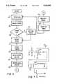
- FIG. 11is a logic flow chart illustrating the signal indication operation of the digital signal processor of the apparatus shown in FIG. 2;
- controlmoves to a block 110. Otherwise, control moves to a block 112.
- the microprocessor 40sets the stored value of the A/D converter 42 to zero, and then moves to a block 112.
- FIG. 13is a graph of the results of this autocorrelation.
- the autocorrelation outputis stored in a buffer array.
- the horizontal axisshows k, the pointer to each element in the autocorrelation output buffer.
- the vertical axisshows R k , the value contained in the k th element of the autocorrelation output buffer.
- kis also the displacement (measured in samples) used in the auto-correlation to compute R k .
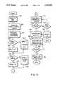
- the digital signal processor 44selects one of the candidate heart rate signals BPM1, BPM2 and BPM3 generated by the digital signal processor 44 at the block 148.
- the value of the selected signalis stored in a variable ARB.
- the value of the five most recent previously selected signalsare stored in an array ARB[0:4], with the most recent result being stored in the array storage element ARB[0].
Landscapes
- Health & Medical Sciences (AREA)
- Life Sciences & Earth Sciences (AREA)
- Engineering & Computer Science (AREA)
- Public Health (AREA)
- Molecular Biology (AREA)
- Cardiology (AREA)
- Veterinary Medicine (AREA)
- Physics & Mathematics (AREA)
- General Health & Medical Sciences (AREA)
- Biophysics (AREA)
- Pathology (AREA)
- Biomedical Technology (AREA)
- Heart & Thoracic Surgery (AREA)
- Medical Informatics (AREA)
- Physiology (AREA)
- Surgery (AREA)
- Animal Behavior & Ethology (AREA)
- Signal Processing (AREA)
- Computer Vision & Pattern Recognition (AREA)
- Artificial Intelligence (AREA)
- Psychiatry (AREA)
- Physical Education & Sports Medicine (AREA)
- Measuring Pulse, Heart Rate, Blood Pressure Or Blood Flow (AREA)
- Measurement And Recording Of Electrical Phenomena And Electrical Characteristics Of The Living Body (AREA)
Abstract
Description
TABLE 1 __________________________________________________________________________Case 0: number of past samples is < = 4 arb = bpm3; Case 1: bpm1 = bpm2 = bpm3 if bpm3 within 25 of arb[0], then arb = bpm3; else if (bpm3 not within 25 of arb[0]) and (arb[0] within 15 of arb[1]), then if bpm3 within 6 of arb[0]*2, then arb = bpm3; else if arb[0] <> any one of other arb array elements, then arb = arb[0] else if bpm3 not within 25 of any element of arb array then, arb = arb[0]; else arb = bpm3; else if (bmp3 not within 25 of arb[0]) and (arb[0] not within 15 of arb[1]), then if arb[0]* 2 within 6 of bpm 3, then arb = bmp3 else if (arb[1] approx = bpm3) and (arb[2] approx = bpm3), then arb = bpm3; else arb = arb[0]; else if 2*bpm3 approx = arb[0], then arb = 2*bpm3; else arb = bpm3; Case 2: (bpm1 = bpm2) and (bpm1 <> bpm3) and (bpm3 <> 0) if bpm1 * 2 = bpm3, then arb = bpm3; else if bpm3 / 2 = arb[0], then arb = bpm1; else if 2 * bpm1 = arb [0], then arb = 2 * bpm1; else if bpm1 / 3 approx = bpm3, then arb = bpm3; else if 2 * bpm3 approx = bpm1, then if bpm3 approx = arb[0], then arb = bpm3; else arb = bpm1}; else if bpm3 approx = arb[0], then arb = bpm3; else if (bpm1 > bpm3) and (bpm1 > arb[0]) and (arb[0] > bpm3), then if (bpm1 - arb[0] < 20), then arb = bpm1; else arb = arb[0]}; else if (bpm1 - arb[0] < = 20) and (arb[0] -bpm3 > 20), then arb = bpm1; else if (2*bpm3 = arb[0]), then arb = 2*bpm3; else if (bpm3 > bpm1) and (bpm3 >= arb[0]) and (arb[0] > bpm1), then if (bpm1 approx = arb[0] and (bpm3 - bpm1 > 10), then arb = bpm1; else if (bpm3 - arb[0] < 20), then arb = bpm3 else arb = arb[0]; else if (bpm3 > bpm1) and (bpm3 > arb[0]) and (arb[0] > bpm1), then if (arb[0] - bpm3 < 20), then arb = bpm3; else arb = arb[0]; else if (bpm1 - bpm3 <= 4), then arb = bpm3; else if (arb[0] not = 0) and (arb[1] not = 0), then arb = arb[0]; else arb = 0; Case 3: (bpm1 = bpm2) and (bpm3 = 0) if (arb[0] not = 0) and (bpm1 - arb[0] > 24), then if (bpm1 / 2 - arb[0] < = 20) and (bpm1 > 100), then arb = bpm1 / 2; else if (bpm1 / 2 - arb[0]< = 20) and bpm1 <= 100, then arb = bpm1; else if (bpm1 approx = arb[1]) and (bpm1 approx = arb[1]), then arb = bpm1; else arb = arb[0]}; else arb = bpm1; Case 4: (bpm1 not = bpm2) and (bpm1 not = bpm3) arb = arb[0]; Case 5: (bpm1 = bpm3) and (bpm1 not = bpm2) if (bpm3 approx = arb[0]), then arb = bpm3; else arb = arb[0]; Case 6: (bpm2 = bpm3) and (bpm1 not = bpm2) if (bpm3 = arb[0]), then arb = bpm3; else arb = arb[0]; Case 7: All other cases arb = 0; -------- END OF TABLE ONE --------- __________________________________________________________________________
Claims (27)
Priority Applications (2)
| Application Number | Priority Date | Filing Date | Title |
|---|---|---|---|
| US07/722,800US5243993A (en) | 1991-06-28 | 1991-06-28 | Apparatus and method for measuring heart rate |
| US08/053,511US5365934A (en) | 1991-06-28 | 1993-04-26 | Apparatus and method for measuring heart rate |
Applications Claiming Priority (1)
| Application Number | Priority Date | Filing Date | Title |
|---|---|---|---|
| US07/722,800US5243993A (en) | 1991-06-28 | 1991-06-28 | Apparatus and method for measuring heart rate |
Related Child Applications (1)
| Application Number | Title | Priority Date | Filing Date |
|---|---|---|---|
| US08/053,511Continuation-In-PartUS5365934A (en) | 1991-06-28 | 1993-04-26 | Apparatus and method for measuring heart rate |
Publications (1)
| Publication Number | Publication Date |
|---|---|
| US5243993Atrue US5243993A (en) | 1993-09-14 |
Family
ID=24903438
Family Applications (1)
| Application Number | Title | Priority Date | Filing Date |
|---|---|---|---|
| US07/722,800Expired - LifetimeUS5243993A (en) | 1991-06-28 | 1991-06-28 | Apparatus and method for measuring heart rate |
Country Status (1)
| Country | Link |
|---|---|
| US (1) | US5243993A (en) |
Cited By (52)
| Publication number | Priority date | Publication date | Assignee | Title |
|---|---|---|---|---|
| EP0650695A3 (en)* | 1993-11-01 | 1996-03-06 | Polar Electro Oy | A method for calculating a fitness index. |
| US5568126A (en)* | 1995-07-10 | 1996-10-22 | Andersen; Stig L. | Providing an alarm in response to a determination that a person may have suddenly experienced fear |
| WO1997017015A1 (en)* | 1995-11-08 | 1997-05-15 | Salutron, Inc. | Ekg based heart rate monitor |
| EP0813895A2 (en) | 1996-06-17 | 1997-12-29 | Life Fitness | Cross training exercise apparatus |
| US5848594A (en)* | 1993-08-16 | 1998-12-15 | Matheson; Leonard N. | Evaluating the work capacity of injured people |
| US6018677A (en)* | 1997-11-25 | 2000-01-25 | Tectrix Fitness Equipment, Inc. | Heart rate monitor and method |
| EP1029507A2 (en) | 1992-05-12 | 2000-08-23 | Life Fitness | Exercie apparatus for maintaining a user's level of exercise |
| US6115629A (en)* | 1999-03-01 | 2000-09-05 | Digital Concepts Of Missouri, Inc. | Two electrode heart rate monitor measuring power spectrum for use with exercise equipment |
| US6430436B1 (en) | 1999-03-01 | 2002-08-06 | Digital Concepts Of Missouri, Inc. | Two electrode heart rate monitor measuring power spectrum for use on road bikes |
| US20020128544A1 (en)* | 1991-03-07 | 2002-09-12 | Diab Mohamed K. | Signal processing apparatus |
| US20040186388A1 (en)* | 2003-03-18 | 2004-09-23 | Massachusetts Institute Of Technology | Heart rate monitor |
| US20040236196A1 (en)* | 1991-03-07 | 2004-11-25 | Diab Mohamed K. | Signal processing apparatus |
| US20050004483A1 (en)* | 2003-07-03 | 2005-01-06 | Chang Yow Industry Co., Ltd. | Bi-point detection type heart-rate monitor and its heart-rate monitoring method |
| US20050051138A1 (en)* | 2003-09-08 | 2005-03-10 | Robert Bosch Corporation | Intake manifold assembly |
| US20050065443A1 (en)* | 2003-09-22 | 2005-03-24 | David Ternes | Cardiac rhythm management system with exercise test interface |
| US20060056641A1 (en)* | 2004-09-15 | 2006-03-16 | Nadjar Hamid S | Method and system for physiological signal processing |
| US20060058677A1 (en)* | 2002-04-26 | 2006-03-16 | Kazutaka Okada | Ultrasonograph |
| US20070244400A1 (en)* | 2005-12-07 | 2007-10-18 | Ed Honda | Compliant biometric sensor apparatus |
| US7376453B1 (en) | 1993-10-06 | 2008-05-20 | Masimo Corporation | Signal processing apparatus |
| US20090018410A1 (en)* | 2006-03-02 | 2009-01-15 | Koninklijke Philips Electronics N.V. | Body parameter sensing |
| US7512515B2 (en) | 1994-11-21 | 2009-03-31 | Apple Inc. | Activity monitoring systems and methods |
| EP2042099A1 (en)* | 2007-09-28 | 2009-04-01 | SELLE ITALIA S.r.l. | Device for detecting heartbeats of a person using cycles and training implements |
| US7552031B2 (en) | 2000-12-15 | 2009-06-23 | Apple Inc. | Personal items network, and associated methods |
| US20090239708A1 (en)* | 2008-03-20 | 2009-09-24 | Holylite Microelectronics Corp. | Heart pulse detector with speed control for treadmill |
| US7640135B2 (en) | 1994-11-21 | 2009-12-29 | Phatrat Technology, Llc | System and method for determining airtime using free fall |
| US7643895B2 (en) | 2006-05-22 | 2010-01-05 | Apple Inc. | Portable media device with workout support |
| US7698101B2 (en) | 2007-03-07 | 2010-04-13 | Apple Inc. | Smart garment |
| US7813715B2 (en) | 2006-08-30 | 2010-10-12 | Apple Inc. | Automated pairing of wireless accessories with host devices |
| US7856339B2 (en) | 2000-12-15 | 2010-12-21 | Phatrat Technology, Llc | Product integrity tracking shipping label, system and associated method |
| US7911339B2 (en) | 2005-10-18 | 2011-03-22 | Apple Inc. | Shoe wear-out sensor, body-bar sensing system, unitless activity assessment and associated methods |
| US7913297B2 (en) | 2006-08-30 | 2011-03-22 | Apple Inc. | Pairing of wireless devices using a wired medium |
| US8019400B2 (en) | 1994-10-07 | 2011-09-13 | Masimo Corporation | Signal processing apparatus |
| US8073984B2 (en) | 2006-05-22 | 2011-12-06 | Apple Inc. | Communication protocol for use with portable electronic devices |
| US20130137936A1 (en)* | 2011-11-30 | 2013-05-30 | Nellcor Puritan Bennett Ireland | Systems and methods for determining respiration information using historical distribution |
| US8560034B1 (en) | 1993-10-06 | 2013-10-15 | Masimo Corporation | Signal processing apparatus |
| US9137309B2 (en) | 2006-05-22 | 2015-09-15 | Apple Inc. | Calibration techniques for activity sensing devices |
| US9402554B2 (en) | 2011-09-23 | 2016-08-02 | Nellcor Puritan Bennett Ireland | Systems and methods for determining respiration information from a photoplethysmograph |
| US9451893B2 (en) | 2014-08-18 | 2016-09-27 | Cameron Health, Inc. | Calculation of self-correlation in an implantable cardiac device |
| WO2017033164A1 (en)* | 2015-08-26 | 2017-03-02 | Analytics For Life | Method and apparatus for wide-band phase gradient signal acquisition |
| US20170095212A1 (en)* | 2015-10-05 | 2017-04-06 | Microsoft Technology Licensing, Llc | Heart rate correction |
| US9675274B2 (en) | 2011-09-23 | 2017-06-13 | Nellcor Puritan Bennett Ireland | Systems and methods for determining respiration information from a photoplethysmograph |
| US9693709B2 (en) | 2011-09-23 | 2017-07-04 | Nellcot Puritan Bennett Ireland | Systems and methods for determining respiration information from a photoplethysmograph |
| US9737266B2 (en) | 2011-09-23 | 2017-08-22 | Nellcor Puritan Bennett Ireland | Systems and methods for determining respiration information from a photoplethysmograph |
| US9868041B2 (en) | 2006-05-22 | 2018-01-16 | Apple, Inc. | Integrated media jukebox and physiologic data handling application |
| US10405760B2 (en) | 2014-03-17 | 2019-09-10 | Koninklijke Philips N.V. | Heart rate monitor system |
| US20190307342A1 (en)* | 2018-04-10 | 2019-10-10 | Simplex Quantum Inc. | Electrocardiographic measurement method and electrocardiographic measurement device |
| US11089988B2 (en) | 2016-06-24 | 2021-08-17 | Analytics For Life Inc. | Non-invasive method and system for estimating arterial flow characteristics |
| US11141114B2 (en) | 2017-03-02 | 2021-10-12 | Analytics For Life Inc. | Method and apparatus for wide-band phase gradient signal acquisition |
| US11147516B2 (en) | 2018-06-18 | 2021-10-19 | Analytics For Life Inc. | Methods and systems to quantify and remove asynchronous noise in biophysical signals |
| US11160466B2 (en) | 2015-10-05 | 2021-11-02 | Microsoft Technology Licensing, Llc | Heart rate correction for relative activity strain |
| US11826126B2 (en) | 2016-09-21 | 2023-11-28 | Analytics For Life Inc. | Method and system for visualization of heart tissue at risk |
| EP4418987A1 (en)* | 2021-10-22 | 2024-08-28 | BIOTRONIK SE & Co. KG | Method and medical device for determining a periodicity of a physiological signal |
Citations (10)
| Publication number | Priority date | Publication date | Assignee | Title |
|---|---|---|---|---|
| US4211237A (en)* | 1977-04-14 | 1980-07-08 | Biotronik Mess- Und Therapiegerate Gmbh & Co. | Method and apparatus for identifying recurring signal patterns |
| US4244021A (en)* | 1979-03-02 | 1981-01-06 | Amf Incorporated | Ergometric exerciser |
| US4248244A (en)* | 1979-04-06 | 1981-02-03 | Charnitski Richard D | Method for measuring heart beat rate and circuit means for same |
| US4281663A (en)* | 1978-05-26 | 1981-08-04 | Pringle Robert D | Physical fitness indicator |
| US4319581A (en)* | 1980-06-19 | 1982-03-16 | Cutter John W | Heart pulse monitoring apparatus |
| US4403184A (en)* | 1978-04-28 | 1983-09-06 | Hewlett-Packard Company | Autocorrelation apparatus and method for approximating the occurrence of a generally periodic but unknown signal |
| GB2165352A (en)* | 1984-09-06 | 1986-04-09 | Ablec Ltd | Measuring heart rate |
| US4898182A (en)* | 1988-02-04 | 1990-02-06 | Brian Hawkins | Apparatus for evaluating heart fitness |
| US4979110A (en)* | 1988-09-22 | 1990-12-18 | Massachusetts Institute Of Technology | Characterizing the statistical properties of a biological signal |
| US5146414A (en)* | 1990-04-18 | 1992-09-08 | Interflo Medical, Inc. | Method and apparatus for continuously measuring volumetric flow |
- 1991
- 1991-06-28USUS07/722,800patent/US5243993A/ennot_activeExpired - Lifetime
Patent Citations (10)
| Publication number | Priority date | Publication date | Assignee | Title |
|---|---|---|---|---|
| US4211237A (en)* | 1977-04-14 | 1980-07-08 | Biotronik Mess- Und Therapiegerate Gmbh & Co. | Method and apparatus for identifying recurring signal patterns |
| US4403184A (en)* | 1978-04-28 | 1983-09-06 | Hewlett-Packard Company | Autocorrelation apparatus and method for approximating the occurrence of a generally periodic but unknown signal |
| US4281663A (en)* | 1978-05-26 | 1981-08-04 | Pringle Robert D | Physical fitness indicator |
| US4244021A (en)* | 1979-03-02 | 1981-01-06 | Amf Incorporated | Ergometric exerciser |
| US4248244A (en)* | 1979-04-06 | 1981-02-03 | Charnitski Richard D | Method for measuring heart beat rate and circuit means for same |
| US4319581A (en)* | 1980-06-19 | 1982-03-16 | Cutter John W | Heart pulse monitoring apparatus |
| GB2165352A (en)* | 1984-09-06 | 1986-04-09 | Ablec Ltd | Measuring heart rate |
| US4898182A (en)* | 1988-02-04 | 1990-02-06 | Brian Hawkins | Apparatus for evaluating heart fitness |
| US4979110A (en)* | 1988-09-22 | 1990-12-18 | Massachusetts Institute Of Technology | Characterizing the statistical properties of a biological signal |
| US5146414A (en)* | 1990-04-18 | 1992-09-08 | Interflo Medical, Inc. | Method and apparatus for continuously measuring volumetric flow |
Non-Patent Citations (6)
| Title |
|---|
| Article Application of Correlation Analysis to the Detection of Periodic Signals in Noise by Y. W. Lee et al., Proceedings of the I.R.E., 1950, pp. 1165 1171.* |
| Article Digital Signal Processing Applications Using the ADSP 2100, Family Applications Handbook, vols. 1, 2, 3 and 4.* |
| Article Spectral Analysis of Electrocardiogram Signals of the Isolated Guinea Pig Heart for the Detection of Arrhythmias by F. I. Chaudhry et al., J. Biomed. Eng., 1982, vol. 4, p. 287, Oct. 1982.* |
| Article--Application of Correlation Analysis to the Detection of Periodic Signals in Noise by Y. W. Lee et al., Proceedings of the I.R.E., 1950, pp. 1165-1171. |
| Article--Digital Signal Processing Applications Using the ADSP-2100, Family Applications Handbook, vols. 1, 2, 3 and 4. |
| Article--Spectral Analysis of Electrocardiogram Signals of the Isolated Guinea Pig Heart for the Detection of Arrhythmias by F. I. Chaudhry et al., J. Biomed. Eng., 1982, vol. 4, p. 287, Oct. 1982. |
Cited By (135)
| Publication number | Priority date | Publication date | Assignee | Title |
|---|---|---|---|---|
| US7530955B2 (en) | 1991-03-07 | 2009-05-12 | Masimo Corporation | Signal processing apparatus |
| US8948834B2 (en) | 1991-03-07 | 2015-02-03 | Masimo Corporation | Signal processing apparatus |
| US7962190B1 (en) | 1991-03-07 | 2011-06-14 | Masimo Corporation | Signal processing apparatus |
| US7383070B2 (en) | 1991-03-07 | 2008-06-03 | Masimo Corporation | Signal processing apparatus |
| US8036728B2 (en) | 1991-03-07 | 2011-10-11 | Masimo Corporation | Signal processing apparatus |
| US7254433B2 (en) | 1991-03-07 | 2007-08-07 | Masimo Corporation | Signal processing apparatus |
| US7215984B2 (en) | 1991-03-07 | 2007-05-08 | Masimo Corporation | Signal processing apparatus |
| US8046042B2 (en) | 1991-03-07 | 2011-10-25 | Masimo Corporation | Signal processing apparatus |
| US8046041B2 (en) | 1991-03-07 | 2011-10-25 | Masimo Corporation | Signal processing apparatus |
| US7469157B2 (en) | 1991-03-07 | 2008-12-23 | Masimo Corporation | Signal processing apparatus |
| US7215986B2 (en) | 1991-03-07 | 2007-05-08 | Masimo Corporation | Signal processing apparatus |
| US8364226B2 (en) | 1991-03-07 | 2013-01-29 | Masimo Corporation | Signal processing apparatus |
| US8128572B2 (en) | 1991-03-07 | 2012-03-06 | Masimo Corporation | Signal processing apparatus |
| US7937130B2 (en) | 1991-03-07 | 2011-05-03 | Masimo Corporation | Signal processing apparatus |
| US20020128544A1 (en)* | 1991-03-07 | 2002-09-12 | Diab Mohamed K. | Signal processing apparatus |
| US7454240B2 (en) | 1991-03-07 | 2008-11-18 | Masimo Corporation | Signal processing apparatus |
| US20040236196A1 (en)* | 1991-03-07 | 2004-11-25 | Diab Mohamed K. | Signal processing apparatus |
| US8942777B2 (en) | 1991-03-07 | 2015-01-27 | Masimo Corporation | Signal processing apparatus |
| EP1029506A2 (en) | 1992-05-12 | 2000-08-23 | Life Fitness | Exercise apparatus |
| EP1029507A2 (en) | 1992-05-12 | 2000-08-23 | Life Fitness | Exercie apparatus for maintaining a user's level of exercise |
| US5848594A (en)* | 1993-08-16 | 1998-12-15 | Matheson; Leonard N. | Evaluating the work capacity of injured people |
| US8560034B1 (en) | 1993-10-06 | 2013-10-15 | Masimo Corporation | Signal processing apparatus |
| US7328053B1 (en) | 1993-10-06 | 2008-02-05 | Masimo Corporation | Signal processing apparatus |
| US7376453B1 (en) | 1993-10-06 | 2008-05-20 | Masimo Corporation | Signal processing apparatus |
| EP0650695A3 (en)* | 1993-11-01 | 1996-03-06 | Polar Electro Oy | A method for calculating a fitness index. |
| US8755856B2 (en) | 1994-10-07 | 2014-06-17 | Masimo Corporation | Signal processing apparatus |
| US8463349B2 (en) | 1994-10-07 | 2013-06-11 | Masimo Corporation | Signal processing apparatus |
| US8126528B2 (en) | 1994-10-07 | 2012-02-28 | Masimo Corporation | Signal processing apparatus |
| US8359080B2 (en) | 1994-10-07 | 2013-01-22 | Masimo Corporation | Signal processing apparatus |
| US8019400B2 (en) | 1994-10-07 | 2011-09-13 | Masimo Corporation | Signal processing apparatus |
| US7640135B2 (en) | 1994-11-21 | 2009-12-29 | Phatrat Technology, Llc | System and method for determining airtime using free fall |
| US7693668B2 (en) | 1994-11-21 | 2010-04-06 | Phatrat Technology, Llc | Impact reporting head gear system and method |
| US8620600B2 (en) | 1994-11-21 | 2013-12-31 | Phatrat Technology, Llc | System for assessing and displaying activity of a sportsman |
| US7512515B2 (en) | 1994-11-21 | 2009-03-31 | Apple Inc. | Activity monitoring systems and methods |
| US8352211B2 (en) | 1994-11-21 | 2013-01-08 | Apple Inc. | Activity monitoring systems and methods |
| US8239146B2 (en) | 1994-11-21 | 2012-08-07 | PhatRat Technology, LLP | Board sports sensing devices, and associated methods |
| US7860666B2 (en) | 1994-11-21 | 2010-12-28 | Phatrat Technology, Llc | Systems and methods for determining drop distance and speed of moving sportsmen involved in board sports |
| US7991565B2 (en) | 1994-11-21 | 2011-08-02 | Phatrat Technology, Llc | System and method for non-wirelessly determining free-fall of a moving sportsman |
| US8036851B2 (en) | 1994-11-21 | 2011-10-11 | Apple Inc. | Activity monitoring systems and methods |
| US5745034A (en)* | 1995-07-10 | 1998-04-28 | Andersen; Stig Lundegaard | Providing an alarm in response to a determination that a person may have suddenly experienced fear |
| US5568126A (en)* | 1995-07-10 | 1996-10-22 | Andersen; Stig L. | Providing an alarm in response to a determination that a person may have suddenly experienced fear |
| US5876350A (en)* | 1995-11-08 | 1999-03-02 | Salutron, Inc. | EKG based heart rate monitor with digital filter and enhancement signal processor |
| US5738104A (en)* | 1995-11-08 | 1998-04-14 | Salutron, Inc. | EKG based heart rate monitor |
| WO1997017015A1 (en)* | 1995-11-08 | 1997-05-15 | Salutron, Inc. | Ekg based heart rate monitor |
| EP0813895A2 (en) | 1996-06-17 | 1997-12-29 | Life Fitness | Cross training exercise apparatus |
| EP1188462A2 (en) | 1996-06-17 | 2002-03-20 | Brunswick Corporation | Cross training exercise apparatus |
| US6018677A (en)* | 1997-11-25 | 2000-01-25 | Tectrix Fitness Equipment, Inc. | Heart rate monitor and method |
| US6115629A (en)* | 1999-03-01 | 2000-09-05 | Digital Concepts Of Missouri, Inc. | Two electrode heart rate monitor measuring power spectrum for use with exercise equipment |
| US6430436B1 (en) | 1999-03-01 | 2002-08-06 | Digital Concepts Of Missouri, Inc. | Two electrode heart rate monitor measuring power spectrum for use on road bikes |
| US10639552B2 (en) | 2000-12-15 | 2020-05-05 | Apple Inc. | Personal items network, and associated methods |
| US7627451B2 (en) | 2000-12-15 | 2009-12-01 | Apple Inc. | Movement and event systems and associated methods |
| US8280682B2 (en) | 2000-12-15 | 2012-10-02 | Tvipr, Llc | Device for monitoring movement of shipped goods |
| US10427050B2 (en) | 2000-12-15 | 2019-10-01 | Apple Inc. | Personal items network, and associated methods |
| US9643091B2 (en) | 2000-12-15 | 2017-05-09 | Apple Inc. | Personal items network, and associated methods |
| US7856339B2 (en) | 2000-12-15 | 2010-12-21 | Phatrat Technology, Llc | Product integrity tracking shipping label, system and associated method |
| US9267793B2 (en) | 2000-12-15 | 2016-02-23 | Tvipr, Llc | Movement monitoring device for attachment to equipment |
| US8688406B2 (en) | 2000-12-15 | 2014-04-01 | Apple Inc. | Personal items network, and associated methods |
| US8660814B2 (en) | 2000-12-15 | 2014-02-25 | Tvipr, Llc | Package management system for tracking shipment and product integrity |
| US7552031B2 (en) | 2000-12-15 | 2009-06-23 | Apple Inc. | Personal items network, and associated methods |
| US8126675B2 (en) | 2000-12-15 | 2012-02-28 | Phatrat Technology, Llc | Product integrity tracking shipping label, and associated method |
| US8280681B2 (en) | 2000-12-15 | 2012-10-02 | Phatrat Technology, Llc | Pressure-based weight monitoring system for determining improper walking or running |
| US8428904B2 (en) | 2000-12-15 | 2013-04-23 | Tvipr, Llc | Product integrity tracking system, shipping label, and associated method |
| US10406445B2 (en) | 2000-12-15 | 2019-09-10 | Apple Inc. | Personal items network, and associated methods |
| US8396687B2 (en) | 2000-12-15 | 2013-03-12 | Phatrat Technology, Llc | Machine logic airtime sensor for board sports |
| US10080971B2 (en) | 2000-12-15 | 2018-09-25 | Apple Inc. | Personal items network, and associated methods |
| US8374825B2 (en) | 2000-12-15 | 2013-02-12 | Apple Inc. | Personal items network, and associated methods |
| US8043220B2 (en)* | 2002-04-26 | 2011-10-25 | Hitachi Medical Corporation | Ultrasonograph |
| US20060058677A1 (en)* | 2002-04-26 | 2006-03-16 | Kazutaka Okada | Ultrasonograph |
| US7139605B2 (en)* | 2003-03-18 | 2006-11-21 | Massachusetts Institute Of Technology | Heart rate monitor |
| US20040186388A1 (en)* | 2003-03-18 | 2004-09-23 | Massachusetts Institute Of Technology | Heart rate monitor |
| US20050004483A1 (en)* | 2003-07-03 | 2005-01-06 | Chang Yow Industry Co., Ltd. | Bi-point detection type heart-rate monitor and its heart-rate monitoring method |
| US20050051138A1 (en)* | 2003-09-08 | 2005-03-10 | Robert Bosch Corporation | Intake manifold assembly |
| US7532924B2 (en)* | 2003-09-22 | 2009-05-12 | Cardiac Pacemakers, Inc. | Cardiac rhythm management system with exercise test interface |
| US8027726B2 (en) | 2003-09-22 | 2011-09-27 | Cardiac Pacemakers, Inc. | Cardiac rhythm management system with exercise test interface |
| US20050065443A1 (en)* | 2003-09-22 | 2005-03-24 | David Ternes | Cardiac rhythm management system with exercise test interface |
| US20090177100A1 (en)* | 2003-09-22 | 2009-07-09 | David Ternes | Cardiac rhythm management system with exercise test interface |
| US20060056641A1 (en)* | 2004-09-15 | 2006-03-16 | Nadjar Hamid S | Method and system for physiological signal processing |
| US7953230B2 (en) | 2004-09-15 | 2011-05-31 | On Semiconductor Trading Ltd. | Method and system for physiological signal processing |
| US11786006B2 (en) | 2005-10-18 | 2023-10-17 | Apple Inc. | Unitless activity assessment and associated methods |
| US9968158B2 (en) | 2005-10-18 | 2018-05-15 | Apple Inc. | Shoe wear-out sensor, body-bar sensing system, unitless activity assessment and associated methods |
| US9578927B2 (en) | 2005-10-18 | 2017-02-28 | Apple Inc. | Shoe wear-out sensor, body-bar sensing system, unitless activity assessment and associated methods |
| US11140943B2 (en) | 2005-10-18 | 2021-10-12 | Apple Inc. | Unitless activity assessment and associated methods |
| US10376015B2 (en) | 2005-10-18 | 2019-08-13 | Apple Inc. | Shoe wear-out sensor, body-bar sensing system, unitless activity assessment and associated methods |
| US12419380B2 (en) | 2005-10-18 | 2025-09-23 | Apple Inc. | Unitless activity assessment and associated methods |
| US10645991B2 (en) | 2005-10-18 | 2020-05-12 | Apple Inc. | Unitless activity assessment and associated methods |
| US8217788B2 (en) | 2005-10-18 | 2012-07-10 | Vock Curtis A | Shoe wear-out sensor, body-bar sensing system, unitless activity assessment and associated methods |
| US8749380B2 (en) | 2005-10-18 | 2014-06-10 | Apple Inc. | Shoe wear-out sensor, body-bar sensing system, unitless activity assessment and associated methods |
| US20110140890A1 (en)* | 2005-10-18 | 2011-06-16 | Apple Inc. | Shoe wear-out sensor, body-bar sensing system, unitless activity assessment and associated methods |
| US7911339B2 (en) | 2005-10-18 | 2011-03-22 | Apple Inc. | Shoe wear-out sensor, body-bar sensing system, unitless activity assessment and associated methods |
| US20070244400A1 (en)* | 2005-12-07 | 2007-10-18 | Ed Honda | Compliant biometric sensor apparatus |
| US20090018410A1 (en)* | 2006-03-02 | 2009-01-15 | Koninklijke Philips Electronics N.V. | Body parameter sensing |
| US8060229B2 (en) | 2006-05-22 | 2011-11-15 | Apple Inc. | Portable media device with workout support |
| US9137309B2 (en) | 2006-05-22 | 2015-09-15 | Apple Inc. | Calibration techniques for activity sensing devices |
| US9154554B2 (en) | 2006-05-22 | 2015-10-06 | Apple Inc. | Calibration techniques for activity sensing devices |
| US8346987B2 (en) | 2006-05-22 | 2013-01-01 | Apple Inc. | Communication protocol for use with portable electronic devices |
| US7643895B2 (en) | 2006-05-22 | 2010-01-05 | Apple Inc. | Portable media device with workout support |
| US8073984B2 (en) | 2006-05-22 | 2011-12-06 | Apple Inc. | Communication protocol for use with portable electronic devices |
| US9868041B2 (en) | 2006-05-22 | 2018-01-16 | Apple, Inc. | Integrated media jukebox and physiologic data handling application |
| US7813715B2 (en) | 2006-08-30 | 2010-10-12 | Apple Inc. | Automated pairing of wireless accessories with host devices |
| US7913297B2 (en) | 2006-08-30 | 2011-03-22 | Apple Inc. | Pairing of wireless devices using a wired medium |
| US8181233B2 (en) | 2006-08-30 | 2012-05-15 | Apple Inc. | Pairing of wireless devices using a wired medium |
| US7698101B2 (en) | 2007-03-07 | 2010-04-13 | Apple Inc. | Smart garment |
| US8099258B2 (en) | 2007-03-07 | 2012-01-17 | Apple Inc. | Smart garment |
| EP2042099A1 (en)* | 2007-09-28 | 2009-04-01 | SELLE ITALIA S.r.l. | Device for detecting heartbeats of a person using cycles and training implements |
| US20090239708A1 (en)* | 2008-03-20 | 2009-09-24 | Holylite Microelectronics Corp. | Heart pulse detector with speed control for treadmill |
| US9675274B2 (en) | 2011-09-23 | 2017-06-13 | Nellcor Puritan Bennett Ireland | Systems and methods for determining respiration information from a photoplethysmograph |
| US9693709B2 (en) | 2011-09-23 | 2017-07-04 | Nellcot Puritan Bennett Ireland | Systems and methods for determining respiration information from a photoplethysmograph |
| US9402554B2 (en) | 2011-09-23 | 2016-08-02 | Nellcor Puritan Bennett Ireland | Systems and methods for determining respiration information from a photoplethysmograph |
| US9737266B2 (en) | 2011-09-23 | 2017-08-22 | Nellcor Puritan Bennett Ireland | Systems and methods for determining respiration information from a photoplethysmograph |
| US20130137936A1 (en)* | 2011-11-30 | 2013-05-30 | Nellcor Puritan Bennett Ireland | Systems and methods for determining respiration information using historical distribution |
| US9693736B2 (en)* | 2011-11-30 | 2017-07-04 | Nellcor Puritan Bennett Ireland | Systems and methods for determining respiration information using historical distribution |
| US10405760B2 (en) | 2014-03-17 | 2019-09-10 | Koninklijke Philips N.V. | Heart rate monitor system |
| US9629565B2 (en) | 2014-08-18 | 2017-04-25 | Cameron Health, Inc. | Peak selection for self correlation analysis of cardiac rate in an implantable medical devices |
| US9451893B2 (en) | 2014-08-18 | 2016-09-27 | Cameron Health, Inc. | Calculation of self-correlation in an implantable cardiac device |
| US9895071B2 (en) | 2014-08-18 | 2018-02-20 | Cameron Health, Inc. | Cardiac rate tracking in an implantable medical device |
| US10016143B2 (en) | 2014-08-18 | 2018-07-10 | Cameron Health, Inc. | Peak selection for self correlation analysis of cardiac rate in an implantable medical device |
| US9451892B2 (en) | 2014-08-18 | 2016-09-27 | Cameron Health, Inc. | Cardiac rate tracking in an implantable medical device |
| US12011275B2 (en) | 2015-08-26 | 2024-06-18 | Analytics For Life, Inc. | Method and apparatus for wide-band phase gradient signal acquisition |
| US10542897B2 (en) | 2015-08-26 | 2020-01-28 | Analytics For Life Inc. | Method and apparatus for wide-band phase gradient signal acquisition |
| WO2017033164A1 (en)* | 2015-08-26 | 2017-03-02 | Analytics For Life | Method and apparatus for wide-band phase gradient signal acquisition |
| US11395618B2 (en) | 2015-08-26 | 2022-07-26 | Analytics For Life Inc. | Method and apparatus for wide-band phase gradient signal acquisition |
| US9949694B2 (en)* | 2015-10-05 | 2018-04-24 | Microsoft Technology Licensing, Llc | Heart rate correction |
| CN108135514B (en)* | 2015-10-05 | 2020-11-06 | 微软技术许可有限责任公司 | Heart rate correction |
| US20170095212A1 (en)* | 2015-10-05 | 2017-04-06 | Microsoft Technology Licensing, Llc | Heart rate correction |
| CN108135514A (en)* | 2015-10-05 | 2018-06-08 | 微软技术许可有限责任公司 | Heart rate corrects |
| US11160466B2 (en) | 2015-10-05 | 2021-11-02 | Microsoft Technology Licensing, Llc | Heart rate correction for relative activity strain |
| WO2017062232A1 (en)* | 2015-10-05 | 2017-04-13 | Microsoft Technology Licensing, Llc | Heart rate correction |
| US11089988B2 (en) | 2016-06-24 | 2021-08-17 | Analytics For Life Inc. | Non-invasive method and system for estimating arterial flow characteristics |
| US12011276B2 (en) | 2016-06-24 | 2024-06-18 | Analytics For Life Inc. | Non-invasive method and system for measuring myocardial ischemia, stenosis identification, localization and fractional flow reserve estimation |
| US11826126B2 (en) | 2016-09-21 | 2023-11-28 | Analytics For Life Inc. | Method and system for visualization of heart tissue at risk |
| US11141114B2 (en) | 2017-03-02 | 2021-10-12 | Analytics For Life Inc. | Method and apparatus for wide-band phase gradient signal acquisition |
| US20190307342A1 (en)* | 2018-04-10 | 2019-10-10 | Simplex Quantum Inc. | Electrocardiographic measurement method and electrocardiographic measurement device |
| US11147516B2 (en) | 2018-06-18 | 2021-10-19 | Analytics For Life Inc. | Methods and systems to quantify and remove asynchronous noise in biophysical signals |
| EP4418987A1 (en)* | 2021-10-22 | 2024-08-28 | BIOTRONIK SE & Co. KG | Method and medical device for determining a periodicity of a physiological signal |
| EP4418987B1 (en)* | 2021-10-22 | 2025-06-18 | BIOTRONIK SE & Co. KG | Method and medical device for determining a periodicity of a physiological signal |
Similar Documents
| Publication | Publication Date | Title |
|---|---|---|
| US5243993A (en) | Apparatus and method for measuring heart rate | |
| US5365934A (en) | Apparatus and method for measuring heart rate | |
| US4938228A (en) | Wrist worn heart rate monitor | |
| US5738104A (en) | EKG based heart rate monitor | |
| US4338950A (en) | System and method for sensing and measuring heart beat | |
| US4120294A (en) | Electrode system for acquiring electrical signals from the heart | |
| US7354383B2 (en) | Jump rope with physiological monitor | |
| US6018677A (en) | Heart rate monitor and method | |
| US5263491A (en) | Ambulatory metabolic monitor | |
| CA1322252C (en) | Apparatus for monitoring degree of mental tension | |
| US7797039B2 (en) | Method for recognizing the heartbeat and for calculating quantities acquired from the heartbeat | |
| JP3559284B2 (en) | Pulse oximeter for heart rate synchronization using virtual trigger | |
| US4248244A (en) | Method for measuring heart beat rate and circuit means for same | |
| US6584344B2 (en) | Method and apparatus for measuring heart rate | |
| US6430436B1 (en) | Two electrode heart rate monitor measuring power spectrum for use on road bikes | |
| US5323783A (en) | Dynamic ST segment estimation and adjustment | |
| CA2033014C (en) | Heart rate monitor | |
| US5840039A (en) | Method and apparatus in connection with measuring the heartbeat rate of a person | |
| CA2006626A1 (en) | Method and apparatus for correlating the display of information contained in two information signals | |
| JP2015178011A (en) | Sleep evaluation apparatus and program | |
| JP3849152B2 (en) | Biological signal detector | |
| JP4055466B2 (en) | Body composition detection device | |
| JP7256936B2 (en) | STRESS MEASUREMENT DEVICE, STRESS MEASUREMENT METHOD AND PROGRAM | |
| JPS63147433A (en) | Heart rate meter | |
| JPH05103766A (en) | Bathtub electrocardiograph |
Legal Events
| Date | Code | Title | Description |
|---|---|---|---|
| AS | Assignment | Owner name:LIFE FITNESS, A NY GENERAL PARTNERSHIP Free format text:ASSIGNMENT OF ASSIGNORS INTEREST.;ASSIGNOR:ENGLEHARDT, WILLIAM H.;REEL/FRAME:005811/0471 Effective date:19910816 Owner name:LIFE FITNESS, A NY GENERAL PARTNERSHIP Free format text:ASSIGNMENT OF ASSIGNORS INTEREST.;ASSIGNOR:SVILANS, OLGERTS J.;REEL/FRAME:005811/0473 Effective date:19910819 Owner name:LIFE FITNESS, A GENERAL PARTNERSHIP OF NY Free format text:ASSIGNMENT OF ASSIGNORS INTEREST.;ASSIGNORS:ALEXANDER, DONALD J.;FULLER, ALLEN J.;MACDONALD, DOUGLAS B.;REEL/FRAME:005811/0469 Effective date:19910819 | |
| AS | Assignment | Owner name:LIFE FITNESS, A NY GENERAL PARTNERSHIP Free format text:ASSIGNMENT OF ASSIGNORS INTEREST.;ASSIGNOR:BONNER, ROBERT A.;REEL/FRAME:005872/0939 Effective date:19910817 | |
| AS | Assignment | Owner name:LIFE FITNESS Free format text:ASSIGNMENT OF ASSIGNORS INTEREST;ASSIGNOR:BALLY MANUFACTURING CORPORATION;REEL/FRAME:006585/0869 Effective date:19930610 | |
| STCF | Information on status: patent grant | Free format text:PATENTED CASE | |
| CC | Certificate of correction | ||
| REMI | Maintenance fee reminder mailed | ||
| FPAY | Fee payment | Year of fee payment:4 | |
| SULP | Surcharge for late payment | ||
| AS | Assignment | Owner name:LIFE FITNESS, ILLINOIS Free format text:RELEASE OF SECURITY INTEREST;ASSIGNOR:SPBC, INC.;REEL/FRAME:008732/0762 Effective date:19940610 Owner name:BRUNSWICK CORPORATION, ILLINOIS Free format text:ASSIGNMENT OF ASSIGNORS INTEREST;ASSIGNOR:LIFE FITNESS;REEL/FRAME:008732/0697 Effective date:19970709 | |
| FPAY | Fee payment | Year of fee payment:8 | |
| FPAY | Fee payment | Year of fee payment:12 | |
| AS | Assignment | Owner name:JPMORGAN CHASE BANK, N.A., TEXAS Free format text:SECURITY AGREEMENT;ASSIGNORS:BRUNSWICK CORPORATION;TRITON BOAT COMPANY, L.P.;ATTWOOD CORPORATION;AND OTHERS;REEL/FRAME:022092/0365 Effective date:20081219 Owner name:JPMORGAN CHASE BANK, N.A.,TEXAS Free format text:SECURITY AGREEMENT;ASSIGNORS:BRUNSWICK CORPORATION;TRITON BOAT COMPANY, L.P.;ATTWOOD CORPORATION;AND OTHERS;REEL/FRAME:022092/0365 Effective date:20081219 | |
| AS | Assignment | Owner name:THE BANK OF NEW YORK MELLON TRUST COMPANY, N.A., I Free format text:SECURITY AGREEMENT;ASSIGNORS:BRUNSWICK CORPORATION;ATTWOOD CORPORATION;BOSTON WHALER, INC.;AND OTHERS;REEL/FRAME:023180/0493 Effective date:20090814 Owner name:THE BANK OF NEW YORK MELLON TRUST COMPANY, N.A.,IL Free format text:SECURITY AGREEMENT;ASSIGNORS:BRUNSWICK CORPORATION;ATTWOOD CORPORATION;BOSTON WHALER, INC.;AND OTHERS;REEL/FRAME:023180/0493 Effective date:20090814 | |
| AS | Assignment | Owner name:LAND 'N' SEA DISTRIBUTING, INC., FLORIDA Free format text:RELEASE BY SECURED PARTY;ASSIGNOR:JPMORGAN CHASE BANK, N.A., AS ADMINISTRATIVE AGENT;REEL/FRAME:026026/0001 Effective date:20110321 Owner name:BRUNSWICK CORPORATION, ILLINOIS Free format text:RELEASE BY SECURED PARTY;ASSIGNOR:JPMORGAN CHASE BANK, N.A., AS ADMINISTRATIVE AGENT;REEL/FRAME:026026/0001 Effective date:20110321 Owner name:BRUNSWICK LEISURE BOAT COMPANY, LLC, INDIANA Free format text:RELEASE BY SECURED PARTY;ASSIGNOR:JPMORGAN CHASE BANK, N.A., AS ADMINISTRATIVE AGENT;REEL/FRAME:026026/0001 Effective date:20110321 Owner name:BRUNSWICK FAMILY BOAT CO. INC., WASHINGTON Free format text:RELEASE BY SECURED PARTY;ASSIGNOR:JPMORGAN CHASE BANK, N.A., AS ADMINISTRATIVE AGENT;REEL/FRAME:026026/0001 Effective date:20110321 Owner name:TRITON BOAT COMPANY, L.P., TENNESSEE Free format text:RELEASE BY SECURED PARTY;ASSIGNOR:JPMORGAN CHASE BANK, N.A., AS ADMINISTRATIVE AGENT;REEL/FRAME:026026/0001 Effective date:20110321 Owner name:BRUNSWICK BOWLING & BILLIARDS CORPORATION, ILLINOI Free format text:RELEASE BY SECURED PARTY;ASSIGNOR:JPMORGAN CHASE BANK, N.A., AS ADMINISTRATIVE AGENT;REEL/FRAME:026026/0001 Effective date:20110321 Owner name:LUND BOAT COMPANY, MINNESOTA Free format text:RELEASE BY SECURED PARTY;ASSIGNOR:JPMORGAN CHASE BANK, N.A., AS ADMINISTRATIVE AGENT;REEL/FRAME:026026/0001 Effective date:20110321 Owner name:BRUNSWICK COMMERICAL & GOVERNMENT PRODUCTS, INC., Free format text:RELEASE BY SECURED PARTY;ASSIGNOR:JPMORGAN CHASE BANK, N.A., AS ADMINISTRATIVE AGENT;REEL/FRAME:026026/0001 Effective date:20110321 Owner name:BOSTON WHALER, INC., FLORIDA Free format text:RELEASE BY SECURED PARTY;ASSIGNOR:JPMORGAN CHASE BANK, N.A., AS ADMINISTRATIVE AGENT;REEL/FRAME:026026/0001 Effective date:20110321 Owner name:ATTWOOD CORPORATION, MICHIGAN Free format text:RELEASE BY SECURED PARTY;ASSIGNOR:JPMORGAN CHASE BANK, N.A., AS ADMINISTRATIVE AGENT;REEL/FRAME:026026/0001 Effective date:20110321 | |
| AS | Assignment | Owner name:JPMORGAN CHASE BANK, N.A., AS ADMINISTRATIVE AGENT Free format text:SECURITY AGREEMENT;ASSIGNORS:BRUNSWICK CORPORATION;ATTWOOD CORPORATION;BOSTON WHALER, INC.;AND OTHERS;REEL/FRAME:026072/0239 Effective date:20110321 | |
| AS | Assignment | Owner name:BRUNSWICK CORPORATION, ILLINOIS Free format text:RELEASE BY SECURED PARTY;ASSIGNOR:THE BANK OF NEW YORK MELLON;REEL/FRAME:031973/0242 Effective date:20130717 | |
| AS | Assignment | Owner name:LAND 'N' SEA DISTRIBUTING, INC., ILLINOIS Free format text:RELEASE BY SECURED PARTY;ASSIGNOR:JPMORGAN CHASE BANK, N.A.;REEL/FRAME:034794/0300 Effective date:20141226 Owner name:LUND BOAT COMPANY, ILLINOIS Free format text:RELEASE BY SECURED PARTY;ASSIGNOR:JPMORGAN CHASE BANK, N.A.;REEL/FRAME:034794/0300 Effective date:20141226 Owner name:ATTWOOD CORPORATION, ILLINOIS Free format text:RELEASE BY SECURED PARTY;ASSIGNOR:JPMORGAN CHASE BANK, N.A.;REEL/FRAME:034794/0300 Effective date:20141226 Owner name:BOSTON WHALER, INC., ILLINOIS Free format text:RELEASE BY SECURED PARTY;ASSIGNOR:JPMORGAN CHASE BANK, N.A.;REEL/FRAME:034794/0300 Effective date:20141226 Owner name:BRUNSWICK CORPORATION, ILLINOIS Free format text:RELEASE BY SECURED PARTY;ASSIGNOR:JPMORGAN CHASE BANK, N.A.;REEL/FRAME:034794/0300 Effective date:20141226 Owner name:BRUNSWICK FAMILY BOAT CO. INC., ILLINOIS Free format text:RELEASE BY SECURED PARTY;ASSIGNOR:JPMORGAN CHASE BANK, N.A.;REEL/FRAME:034794/0300 Effective date:20141226 Owner name:BRUNSWICK COMMERCIAL & GOVERNMENT PRODUCTS, INC., Free format text:RELEASE BY SECURED PARTY;ASSIGNOR:JPMORGAN CHASE BANK, N.A.;REEL/FRAME:034794/0300 Effective date:20141226 Owner name:BRUNSWICK LEISURE BOAT COMPANY, LLC, ILLINOIS Free format text:RELEASE BY SECURED PARTY;ASSIGNOR:JPMORGAN CHASE BANK, N.A.;REEL/FRAME:034794/0300 Effective date:20141226 Owner name:BRUNSWICK BOWLING & BILLIARDS CORPORATION, ILLINOI Free format text:RELEASE BY SECURED PARTY;ASSIGNOR:JPMORGAN CHASE BANK, N.A.;REEL/FRAME:034794/0300 Effective date:20141226 |