US5243598A - Microcell system in digital cellular - Google Patents
Microcell system in digital cellularDownload PDFInfo
- Publication number
- US5243598A US5243598AUS07/679,521US67952191AUS5243598AUS 5243598 AUS5243598 AUS 5243598AUS 67952191 AUS67952191 AUS 67952191AUS 5243598 AUS5243598 AUS 5243598A
- Authority
- US
- United States
- Prior art keywords
- zone
- cell
- zones
- signals
- cell according
- Prior art date
- Legal status (The legal status is an assumption and is not a legal conclusion. Google has not performed a legal analysis and makes no representation as to the accuracy of the status listed.)
- Expired - Lifetime
Links
- 230000001413cellular effectEffects0.000titleclaimsabstractdescription15
- 238000004891communicationMethods0.000claimsabstractdescription32
- 230000005540biological transmissionEffects0.000claimsabstractdescription30
- 230000008878couplingEffects0.000claimsdescription18
- 238000010168coupling processMethods0.000claimsdescription18
- 238000005859coupling reactionMethods0.000claimsdescription18
- 230000004044responseEffects0.000claimsdescription5
- 238000012544monitoring processMethods0.000claimsdescription2
- 230000007274generation of a signal involved in cell-cell signalingEffects0.000claims2
- 238000010586diagramMethods0.000description23
- 238000000034methodMethods0.000description10
- 230000000875corresponding effectEffects0.000description9
- 230000008901benefitEffects0.000description7
- 238000012545processingMethods0.000description5
- 230000000694effectsEffects0.000description3
- 230000001788irregularEffects0.000description3
- 239000013307optical fiberSubstances0.000description3
- 230000008569processEffects0.000description3
- 230000009471actionEffects0.000description2
- 230000008859changeEffects0.000description2
- 238000010276constructionMethods0.000description2
- 238000005562fadingMethods0.000description2
- 238000012986modificationMethods0.000description2
- 230000004048modificationEffects0.000description2
- 238000000926separation methodMethods0.000description2
- 238000001228spectrumMethods0.000description2
- 230000003466anti-cipated effectEffects0.000description1
- 239000000969carrierSubstances0.000description1
- 230000001276controlling effectEffects0.000description1
- 238000012937correctionMethods0.000description1
- 230000002596correlated effectEffects0.000description1
- 230000007423decreaseEffects0.000description1
- 230000001419dependent effectEffects0.000description1
- 238000001514detection methodMethods0.000description1
- 238000005516engineering processMethods0.000description1
- 230000000977initiatory effectEffects0.000description1
- 230000003287optical effectEffects0.000description1
- 238000010845search algorithmMethods0.000description1
- 239000004065semiconductorSubstances0.000description1
- 230000011664signalingEffects0.000description1
- 230000002123temporal effectEffects0.000description1
Images


Classifications
- H—ELECTRICITY
- H04—ELECTRIC COMMUNICATION TECHNIQUE
- H04W—WIRELESS COMMUNICATION NETWORKS
- H04W16/00—Network planning, e.g. coverage or traffic planning tools; Network deployment, e.g. resource partitioning or cells structures
- H04W16/24—Cell structures
- H04W16/26—Cell enhancers or enhancement, e.g. for tunnels, building shadow
- H—ELECTRICITY
- H04—ELECTRIC COMMUNICATION TECHNIQUE
- H04B—TRANSMISSION
- H04B7/00—Radio transmission systems, i.e. using radiation field
- H04B7/02—Diversity systems; Multi-antenna system, i.e. transmission or reception using multiple antennas
- H04B7/04—Diversity systems; Multi-antenna system, i.e. transmission or reception using multiple antennas using two or more spaced independent antennas
- H04B7/0491—Diversity systems; Multi-antenna system, i.e. transmission or reception using multiple antennas using two or more spaced independent antennas using two or more sectors, i.e. sector diversity
- H—ELECTRICITY
- H04—ELECTRIC COMMUNICATION TECHNIQUE
- H04B—TRANSMISSION
- H04B7/00—Radio transmission systems, i.e. using radiation field
- H04B7/02—Diversity systems; Multi-antenna system, i.e. transmission or reception using multiple antennas
- H04B7/04—Diversity systems; Multi-antenna system, i.e. transmission or reception using multiple antennas using two or more spaced independent antennas
- H04B7/08—Diversity systems; Multi-antenna system, i.e. transmission or reception using multiple antennas using two or more spaced independent antennas at the receiving station
- H04B7/0802—Diversity systems; Multi-antenna system, i.e. transmission or reception using multiple antennas using two or more spaced independent antennas at the receiving station using antenna selection
- H—ELECTRICITY
- H04—ELECTRIC COMMUNICATION TECHNIQUE
- H04B—TRANSMISSION
- H04B7/00—Radio transmission systems, i.e. using radiation field
- H04B7/02—Diversity systems; Multi-antenna system, i.e. transmission or reception using multiple antennas
- H04B7/022—Site diversity; Macro-diversity
- H—ELECTRICITY
- H04—ELECTRIC COMMUNICATION TECHNIQUE
- H04B—TRANSMISSION
- H04B7/00—Radio transmission systems, i.e. using radiation field
- H04B7/02—Diversity systems; Multi-antenna system, i.e. transmission or reception using multiple antennas
- H04B7/04—Diversity systems; Multi-antenna system, i.e. transmission or reception using multiple antennas using two or more spaced independent antennas
- H04B7/08—Diversity systems; Multi-antenna system, i.e. transmission or reception using multiple antennas using two or more spaced independent antennas at the receiving station
- H04B7/0837—Diversity systems; Multi-antenna system, i.e. transmission or reception using multiple antennas using two or more spaced independent antennas at the receiving station using pre-detection combining
- H—ELECTRICITY
- H04—ELECTRIC COMMUNICATION TECHNIQUE
- H04W—WIRELESS COMMUNICATION NETWORKS
- H04W36/00—Hand-off or reselection arrangements
- H04W36/16—Performing reselection for specific purposes
- H04W36/18—Performing reselection for specific purposes for allowing seamless reselection, e.g. soft reselection
- H—ELECTRICITY
- H04—ELECTRIC COMMUNICATION TECHNIQUE
- H04W—WIRELESS COMMUNICATION NETWORKS
- H04W72/00—Local resource management
- H04W72/50—Allocation or scheduling criteria for wireless resources
- H04W72/54—Allocation or scheduling criteria for wireless resources based on quality criteria
- H04W72/542—Allocation or scheduling criteria for wireless resources based on quality criteria using measured or perceived quality
Definitions
- This inventionrelates generally to cellular telephone systems. More particularly, the invention relates to a digital multiple access communication system for cellular telephone systems.
- a plurality of contiguous cellsare arranged with handoff means for maintaining continuous communication with mobile telephones moving from cell to cell.
- a handoffoccurs which switches the mobile unit from a frequency in the set assigned to the cell it is leaving, to a new frequency in the set assigned to the cell it is entering.
- the handoff actionis controlled by a mobile telephone switching office (MTSO) which receives a handoff command or instruction.
- MTSOmobile telephone switching office
- the handoff commandis typically generated when the signal received from the mobile telephone falls below a preselected signal strength thus indicating that the mobile telephone is at the cell boundary.
- each cell in a cellular telephone systemoperates with a different assigned set of transmission frequencies.
- the handoff signalinstructs the cell which the mobile telephone is entering to begin transmitting at a frequency which is different from the frequency which was being transmitted by the cell which the mobile telephone was leaving.
- a similar procedureis followed when the mobile telephone passes into the next contiguous cell.
- Sets of assigned frequenciesare different for adjacent cells, and such sets are not repeated except for cells that are far enough away from each other so that interference problems will not occur.
- the identification codesare generally not repeated.
- a mobile telephone unittypically contains a control unit, a transceiver, and an antenna system.
- Each cell sitetypically is provided with a control unit, radio, a power plant, data terminals, and antennas.
- the MTSOprovides coordination for all the cell sites and contains suitable processing and switching means.
- the MTSOalso interfaces with the telephone company zone offices for standard hardwired telephone systems.
- the communication links between the MTSO and the various cell sitesare typically microwave, T carriers, or optical fiber, and carry both voice and control data between the cell sites and the MTSO.
- the receiverWhen a user sitting in a car activates the receiver of the mobile unit, the receiver scans a plurality of set-up channels which are designated among the total channels assigned to the cell. Typically, there may be 21 set-up channels out of a total of 416 channels. (The remainder are communication channels.) The receiver then selects the strongest set-up channel and locks on for a certain time. Each site is assigned a different set-up channel. Accordingly, locking onto the strongest set-up channel usually means selecting the nearest cell site.
- This self-location schemeis used in the idle stage and is user-independent. It has a great advantage because it eliminates the load on the transmission at the cell site for locating the mobile unit. The disadvantage of the self-location scheme is that no location information of idle mobile units appears at each cell site.
- the paging processis longer. Since a large percentage of calls originates at the mobile unit, the use of self-location schemes is justified. After a delay, for example, one minute, the self-location procedure is repeated.
- the userplaces the called number into an originating register in the mobile unit, checks to see that the number is correct, and pushes a "send" button.
- a request for serviceis sent on a selected set-up channel obtained from a self-location scheme as described above.
- the cell sitereceives it, and in directional cell sites, selects the best directive antenna for the voice channel to use.
- the cell sitesends a request to the MTSO via a high-speed data link.
- the MTSOselects an appropriate voice channel for the call, and the cell site acts on it through the best directive antenna to link the mobile unit.
- the MTSOalso connects the wire-line party through the telephone company central office.
- the telephone company central officerecognizes that the called number is mobile and forwards the call to the MTSO.
- the MTSOsends a paging message to certain cell sites based on the mobile unit number and a suitable search algorithm.
- Each cell sitetransmits the page on its own set-up channel.
- the mobile unitrecognizes its own identification on a strong set-up channel, locks onto it, and responds to the cell site.
- the mobile unitalso follows the instruction to tune to an assigned voice channel and initiate an audible signal to alert the user to the incoming call.
- the hang upturns off the transmitter, and a particular signal (signaling tone) transmits to the cell site and both sides free the voice channel.
- the mobile unitresumes monitoring pages through the strongest set-up channel.
- a calltwo parties are on a voice channel.
- the present cell siterequests a handoff via an appropriate signal, for example, a 100 ms burst on the voice channel.
- the systemswitches the call to a new frequency channel or a different cell identification code in a new cell site without either interrupting the call or alerting the user.
- the callcontinues as long as the user is talking. The user does not notice the handoff occurrences.
- increased capacitymay be generated by reducing the area covered by a particular cell, i.e., creating a microcell. For example, if a cell is split into four smaller cells, each with a radius of one-half the original, traffic is increased four fold. Naturally, the smaller the cell, the more handoffs required in a cellular telephone system for a given capacity.
- a cellular telephone system in which an antenna set configuration leads to a more uniform signal coverage contour and lowered interference levelsis described in U.S. Pat. No. 4,932,049 issued to Lee.
- the cellular telephone systemcomprises cells which contain a plurality of antenna sets arranged and configured to limit propagation of signals substantially to one of a plurality of zones or sectors within the boundaries of the cells.
- the zones or sectorsare substantially less in area than the area of the cell. Transmission at any one frequency (of the assigned set of transmission frequencies for the cell) is confined to the zone or sector wherein the mobile telephone has been assigned to such one frequency. Frequency handoff occurs while the mobile unit moves to a different cell.
- multiple access schemesallowing more than one user to use a communication channel could be implemented in the cell.
- Multiple accessis possible because most users of a voice communication system do not fully utilize the capacity of the communication system. More specifically, a typical user who is allocated a channel in the communication system only actively uses the voice channel for a fraction of its allocated time. As an example, a typical user using a voice channel generally speaks for half of the time and listens for the remaining times. Thus the communication channel is then left unused for at least half of the time.
- bursts or pockets of voice signals for different users in digital systemsmay be transmitted thereby increasing the user capacity of the system.
- Analog multiple access schemessuch as analog frequency division multiple access have been implemented in cellular telephone systems.
- Digital multiple access schemesincluding digital frequency division multiple access, time division multiple access, and code division multiple access have been developed, and it is anticipated that they will also be implemented in cellular telephone systems. It is advantageous to implement a multiple access scheme using digital means. This is because digital communication typically offers better performance, higher capacity, and lower cost. It should be noted that the applications of digital communication are not limited to communicating digital data.
- Analog voice signalcan enjoy the benefits of digital communication by first converting the analog voice signal to a digital signal before transmission. After the digital signal is received by a receiver, the digital signal is then converted back to the analog voice signal.
- the systemis more tolerant to noise. This is because a threshold level of noise energy is required to change the state of a digital signal.
- the communicationis relatively error free if the noise energy of the communication medium is below the required level.
- itis possible to implement error detection and correction algorithms which further reduce the error rate even if the communication medium is relatively noisy. As a result, it is possible to set up communication channels under noisy environment thereby increasing the capacity of the communication system.
- an improved cell configurationleads to a more uniform signal coverage contour, lowered interference levels, increased capacity, improved voice quality, and relatively simple and economical construction.
- the improved cellincludes a master site and a plurality of zone sites.
- the improved cellalso includes a plurality of antenna sets, each set being suitably positioned within the periphery of the cell to cover a corresponding zone and having transmitting and receiving means directionally configured to limit propagation of signals substantially to a zone within the boundaries of the cell.
- At least one of the transmission frequencies for the cellis assigned to more than one mobile telephone located in the cell.
- a characteristic information signalis allocated to each mobile telephone assigned to a given frequency. The strength of the signals received in each zone by each of the antenna sets is monitored at the master site.
- Transmission of each characteristic information signal of each frequency in the assigned set of transmission frequencies for the cellis confined to a selected antenna set in the zone which receives the strongest signal, and transmission is terminated at the antenna sets in other zones. This confines transmission at such characteristic information signal to the zone associated with the selected antenna set.
- FIG. 1is a schematic diagram illustrating a typical layout of a cell employed in the invention.
- FIG. 2is a schematic diagram illustrating another layout of a cell employed in the invention.
- FIG. 3is a schematic block diagram of the electronics of an embodiment of the present invention.
- FIG. 4is a schematic block diagram of a zone select transmitter system according to the present invention.
- FIG. 5is a schematic block diagram of an embodiment of a zone site selector according to the present invention.
- FIG. 6is a schematic block diagram of another embodiment of a zone site selector according to the present invention.
- FIG. 7is a schematic block diagram of a scanning receiver system according to the present invention.
- FIG. 8is a schematic of a master site according to the present invention wherein set up channel is transmitted and received through zone sites.
- FIG. 9is a schematic diagram illustrating a typical layout of a cell in a code division multiple access (CDMA) system according to the present invention.
- CDMAcode division multiple access
- FIG. 10is a schematic block diagram of the electronics in a CDMA system according to the present invention.
- digital multiple accessThere are three main types of digital multiple access systems: digital frequency division multiple access (digital FDMA), time division multiple access (TDMA) and code division multiple access (CDMA).
- digital FDMAdigital frequency division multiple access
- TDMAtime division multiple access
- CDMAcode division multiple access
- the present inventionallows the implementation of digital FDMA, TDMA, and CDMA in a microcell.
- the benefits of digital multiple access communicationcan be realized in the microcell.
- the present invention relating to the digital frequency division multiple accesscan also be applied to an analog frequency division multiple access system by a person of ordinary skill in the art.
- Frequency division multiple accessboth analog and digital is a method whereby the bandwidth of a communication channel is subdivided in frequency into subchannels so that more than one user can use the communication channel simultaneously.
- TDMAis a method whereby the time of operation of a communication system is divided into a plurality of time slots having predetermined lengths.
- the systemtransmits information relating to a user only during the time slots assigned to the user.
- the systemhas means to temporarily store information generated by the user during other times so that information is not lost during these times. Thus, more than one user is able to use the same channel in the communication system.
- the bandwidth of a channelis 30 KHz.
- Three callershave access to a particular channel. Communication time is divided into time frames of 20 ms and the time frames are divided into three slots of 6.66 ms each. Each mobile unit is assigned one of the three time slots in a particular channel.
- CDMAis a method whereby each user is assigned a different coding scheme instead of being assigned a different frequency channel or a different time slot.
- These coding schemesare orthogonal or partially correlated to each other so that it is possible to identify the user based on an analysis of the codes used in the transmission. As a result, more than one user can use the same channel.
- CDMAis especially desirable if the communication channel is relatively noisy. This is because CDMA typically uses spread spectrum techniques which are known to be tolerant to noise and multipath interference. As a result, CDMA allows more users to use the noisy channel to make initial calls thereby increases the capacity of the channel.
- CDMAcode division multiple access
- every celluses the same set of wide band frequencies, or channels.
- the closest co-channel separationi.e., the ratio of the co-channel separation distance (D) and the cell radius (R) in a CDMA system could be equal to 2, whereas the ratio D/R for other communication methods is about 4.6.
- the coding scheme in CDMAhas a code for identifying the cells. As mobile units move from cell to cell, only the identification codes for the cells need to be changed. Such change in the identification code instead of changing frequency is referred to as "soft" handoff. As a result, the performance of the system improves.
- FIG. 1An example of a microcell in which the system according to the present invention can be used is shown in a cell 1 of FIG. 1.
- the structure of cell 1is disclosed in U.S. Pat. No. 4,932,049 issued to Lee, which is incorporated herein by reference. This structure leads to a more uniform signal coverage contour and lowered interference levels.
- the outer boundary of cell 1is delineated by the circle 11 in solid line.
- cellsare often represented as hexagons in designed illustrations. In reality, however, due to the shape of terrain and the presence of buildings and other structures, the actual boundary of the circle 11 may be of an irregular shape.
- the solid line 11is intended to represent that location at which a mobile telephone unit passes from the influence of the illustrated cell and into the influence of an adjacent cell.
- Antenna set 13is located at a zone site 14, whereas antenna sets 15 and 17 are located at zone site 16 and 18, respectively.
- One of the zone sitesfor example, zone site 14, can colocate with a master site which processes the signal to and from the zone sites.
- zone site 14can colocate with a master site which processes the signal to and from the zone sites.
- other numbers of antenna setsmay be usefully employed, and it is to be understood that the use of three sets in FIG. 1 is for illustrative purposes only.
- Each antenna setincludes a transmitting antenna 13a, 15a, and 17a, respectively.
- Each antenna setalso includes two receiving antennas 13b and 13c, 15b and 15c, and 17b and 17c, respectively.
- Duplication of the receiving antennas at each zone siteis for diversity use to reduce signal fading by combining the signals.
- the determination of the locations of zone sites and the number of zone sites in a cellcan be based on the Lee's coverage prediction model published in IEEE Transactions on Vehicular Technology, February, 1988.
- Each antenna sethas its own zone of major influence for transmitting and receiving signals.
- antenna set 13 at the master site 14has a zone indicated by the dotted line 13z.
- antenna set 15 at zone site 16has a zone of influence designated by the dotted line 15z and antenna set 17 at the zone site 18 has a zone of influence designated by the dotted line 17z. It may be seen from FIG. 1 that the zones overlap in certain areas.
- Directionalityis provided to the antenna sets so that the zones of influence, i.e. the zones of propagation and reception of signals, are limited to be substantially within the boundaries of cell 1.
- suitable meanssuch as shown as a symbolic means 19 arranged at each antenna set or zone site.
- the directionality means 19can be a reflector for each individual antenna, or any other suitable arrangement to provide the desired directionality and coverage.
- the signal of the set up channelscan be communicated to the mobile units inside cell 1 in two different configurations.
- the first configurationuses an additional antenna set in the master site, in this case, zone site 14.
- antenna set 13includes a setup transmitting antenna 13d for transmitting set up signals, and duplicate setup receiving antennas 13e and 13f for receiving set up signals, as will be explained below.
- the set of setup antennas 13d, 13e and 13fis configured to have a greater zone of influence, this being indicated by the dash-dot line 21, substantially coextensive with the limits of cell 1 delineated by circle 11.
- the second configurationuses the same sets of antenna 13a-c, 15a-c, and 17a-c for communicating both the voice channel and set up channel. In this configuration, no additional antenna set is required.
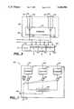
- FIG. 2is another example of microcell 110 in which the system according to the present invention can be used.
- Microcell 110is preferably positioned along a highway 150 for providing cellular telephone services to mobile units (not shown) moving along highway 150.
- Microcell 110comprises a plurality of zones, illustrated by the dotted circles 113-116. It is to be understood that the number of zones in FIG. 2 and the shape of the zones are for illustrative purposes only.
- Each zonecomprises a zone site for housing at least one antenna set.
- zones 113-116comprises zone sites 123-126 and antenna sets 133-136.
- One of the zone sitescan also be a master site.
- microcell 110is that a long stretch of highway 150 can be covered by a set of assigned frequencies. Thus, a mobile unit can travel a long distance without the need for a handoff action.
- the power radiated by antennas 133-136could be low and still cover the stretch of highway because the area of each zone is small. As a result, the microcell 110 could be implemented using low cost equipment.
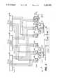
- FIG. 3shows a block diagram of the electronics which can be used either in a TDMA or in a digital FDMA located in the cell of FIG. 1.
- Two zone sites 16 and 18are each coupled to a master site 14 and are controlled therefrom.
- zone site 16is connected to master site 14 via three cables 23, 25, and 27.
- Zone site 18is connected to master site 14 via cables 29, 31, and 33.
- cables 23 and 29carry transmitter antenna signals whereas cables 25, 27, 31, and 33, carry receiver antenna signals.
- the illustrated embodimentdepicts the communication between the zone sites and the master site as being via cable. It will be apparent to those skilled in the art that such cables may include, for example, T1 carrier cables, optical fibers, or the like.
- the cablesmay also be replaced by microwave channels.
- the zone siteseach contain a signal processing ensemble of components as shown at 35 for zone site 14a. It is understood that substantially identical signal processing ensembles are contained in zone sites 16 and 18, although such ensemble are not shown in FIG. 3 for simplicity.
- Signal processing ensemble 35includes a filter 37, an amplifier 39, and a converter 41 interposed between antenna 13a and output cable 43.
- filter 45, amplifier 47, and converter 49are interposed between antenna 13b and output cable 51
- filter 53, amplifier 55, and converter 57are interposed between antenna 13c and output cable 59.
- the filters, amplifiers, and convertersfilter, enhance, and convert signals as desired and may be of any type suitable for the stated purpose.
- the three amplifiers 39, 47, and 55enhance the UHF signals applied to their input from filters 37, 45, and 53 respectively. These UHF signals are then applied to converters 41, 49 and 57, which either up convert or amplitude modulate the frequency to an optical frequency, where optical fibers are used for the cable connections, or down convert the frequency to a base band for passing through T1 carrier cables. They may also directly convert from UHF to microwave where microwave channels are used.
- the filters, amplifiers and convertersmay be of any type suitable for the stated purpose.
- Master site 14comprises a zone selector 95, a transmitter module 96, a receiver module 97, a controller 98, and a set up channel 99. Controller 98 communicates with the MTSO.
- Transmitter module 96comprises a plurality of transmitters. Each transmitter generates a signal having a frequency corresponding to the assigned frequency of a channel. The signals generated from the transmitters in transmitter module 96 is coupled to the appropriate zone site through zone selector 95 for communication with the mobile units. Zone selector 95 also receives signals from the three zone sites, and, after processing these signals in a manner described below, couple the signal to receiver module 97.
- Receiver module 97comprises a plurality of receivers for recovering the signals generated by mobile units in the cell.
- Each receiveris a two-branch diversity receiver, well known in the art, which comprises two inputs, each input accepting a signal from one of the two receiving antenna in the zone site. Each receiver is tuned to a frequency corresponding to the assigned frequency of a channel. The recovered signals are coupled to controller 98.
- Zone selector 95comprises a zone switch 92, a zone switch/combiner 94, and a zone scanner 93.
- Zone switch 92receives signal from transmitter module 96 and directs the signal to the appropriate zone site for communication with the mobile units.
- An exemplary implementation of zone switch 92is shown at FIG. 4.
- the selection of the appropriate zone siteis determined by a selection signal generated by zone scanner 93.
- An exemplary implementation of zone scanner 93is shown at FIG. 7.
- Zone switch/combiner 94receives signal from the zone sites, and, depending on the mode of operations, described below, either combines the signals from the three zone sites or selects a signal from one zone before coupling the resulting signal to receiver module 97.
- Exemplary implementations of zone switch/combiner 94are shown at FIGS. 5 and 6.
- zone switch 92At master site 14, the output ports 71-73 of zone switch 92 go through converters 61-63, respectively, and then coupled to zone sites 14a, 18 and 16, respectively, through cable connectors 43, 29, and 23, respectively.
- the selection of the appropriate zone siteis determined by a selection signal generated by a zone scanner which is input to zone switch 92 through an input port 87.
- Zone switch 92also has an input port 88 for inputting a set of transmitting signals generated by transmitter module 96.
- Zone scanner 93comprises three input ports 81-83 for coupling signals from the three zone sites via converters 64-66, respectively. The strength of these signals are compared to determine the zone site which gives rise to the strongest signal. Alternatively, the zone site can also be selected based on the supervisory audio tone (SAT) signal. Zone scanner 93 also comprises an input port 85 for accepting a time division clock signal from receiver module 97 for separating the appropriate time slot. The selection signal generated by zone scanner 93 is sent to an output port 84 for coupling to zone switch/combiner 94 and zone switch 92.
- SATsupervisory audio tone
- zone switch/combiner 94The signal received from the three zone sites, after going through cable connectors 25, 27, 31, 33, 51, 59, and converters 64-69, terminates at the input ports 74-79 of zone switch/combiner 94. If zone switch/combiner 94 operates in a zone switching mode, a selection signal is coupled to an input port 89. The selection signal selects one of the signals from one of the three zone sites for coupling to the output ports 90, 91. If zone switch/combiner 94 operates in a combing mode such that the signals from all the zones are combined, the selection signal is not used. Zone switch/combiner 94 generates two sets of output signals, one at an output port 90 and the other at an output port 91. Each member of each set of output signals is coupled to a corresponding input terminal of a two-branch diversity receiver in receiver module 97.
- Controller 98measures the signal strength of a channel requested by the MTSO. If the initial call is in this particular cell, or if the call is handed off to this particular cell through the controller, the controller initiates one of the transmitters in transmitter module 96 to transmit at a particular frequency assigned by a MTSO to that call. The signal is then sent to a proper zone through zone switch 92. If during the call, the signal strength received at controller 98 is below a preselected level, the controller initiates a handoff process from the MTSO to handoff the call to another cell.
- controller 98is connected to a set up channel 99 which transmits and receives signals on the three control antennas 13d, 13e, and 13f.
- the set up channel assigned in each cellcan cover the entire zone of influence 21, shown in FIG. 1, which is coextensive with cell 1 in FIG. 1.
- An exemplary setup channel which does not use setup channel antennasis shown in FIG. 8.
- a mobile unit which is operating on an assigned frequency f 1 in the cellwill typically be moving within the cell. All zone sites within the cell will receive signal levels (strengths), but only that zone site at which the received signal level is the strongest will transmit and receive signals to the mobile unit during a call. The transmitters in the other zone sites do not transmit to the mobile unit.
- the systemoperates to turn off the transmitter at the weaker zone site and turn on the transmitter at the zone site at which the stronger signal level is being received.
- the two-diversity antenna signal at each zoneare also selected from the proper zone site to receive the call.
- the operating frequencyremains unchanged at f 1 .
- no handoffhas occurred in the traditional sense and the MTSO is not involved.
- no additional handoff loadis added to the MTSO switching equipment.
- An alternative wayis to combine the two diversity antenna signals from all zones, as described below.
- the block diagram shown in FIG. 3can be used both in digital FDMA and TDMA.
- a TDMA schemea plurality of time division multiplexers and an associated synchronization clock is used, as explained below.
- a digital FDMA schemeit is not necessary to use the time division multiplexers and the associated clock.
- FIG. 4shows a block diagram of an exemplary zone switch, shown as numeral reference 92 in FIG. 3, according to the present invention.
- Zone switch 200comprises two input port 283, 285 and three output ports 211-213 which correspond to ports 87, 88, and 71-73, respectively, of zone switch 92 in FIG. 3.
- signals from a transmitter module, shown as 96 in FIG. 3is coupled to input port 285 of zone switch 200. These signals are directed by zone switch 200 to the three zone sites 14a, 18, and 16 through output ports 211-213.
- transmitter module 96comprises a plurality of transmitters, each generating a different signal.
- Input port 285further comprises a plurality of input terminals, shown as 286 and 287 in FIG. 4.
- Terminal 286couples a signal having a frequency of f 1 into zone switch 200 and terminal 287 couples a signal having a frequency of f 2 into transmitting zone switch 200.
- Zone switch 200further comprises a plurality of time division multiplexers, two of them, 251 and 261 are shown at FIG. 4 for illustrative purpose. In general, the number of time division multiplexers is the same as the number of frequency channels assigned to the cell. Zone switch 200 also comprises a plurality of channel zone switches, six of them, 241-246, are shown at FIG. 4. In general, the number of zone switches is equal to the product of the number of time slots and the number of time division multiplexers. Zone switch 200 further comprises three combiners 221-223, one associated with each zone site, for combining the signals from the channel zone switches for sending to the three zone sites.
- a time division multiplexeris a device, well known in the art, for dividing time intervals into time slots.
- TDM 251 and 261divide each time interval into three time slots.
- Preferably each time slotis 6.66 ms long in a 20 ms time interval. It may be understood that a TDM can divide time intervals into any suitable number of time slots, and the choice of the number of divisions in TDM 251 and 261 are for illustrative purposes only.
- TDM 251comprises an input port 253 for accepting signals having a frequency of f 1 , generated by a transmitter of transmitter module 96, shown in FIG. 3.
- the time interval for transmitting the signal having frequency f 1is divided into three time slots.
- the signals of the time slotsare coupled to output ports 256-257. Each of these signals is eventually directed to a zone site for communicating with a mobile unit. Since different time slots can be directed to different zone sites, it is possible that three mobile units in three zone sites communicate with master site 14 using the same frequency channel.
- TDM 261comprises an input port 263 and three output ports 266-268. Ports 263 and 266-268 correspond to ports 253 and 256-258, respectively, of TDM 251. TDM 261 functions in a similar way as TDM 251. All the output signals from TDM 261 have frequency f 2 since the input signal to TDM 261 has a frequency of f 2 . Again, signals having frequency f 2 in the three time slots can be directed to the same or different zone sites.
- Each of the output ports from the TDMsis coupled to a channel zone switch for directing the output of a communication channel from the TDMs to the appropriate zone site.
- output ports 256-258 and 266-268are coupled to channel zone switches 241-246, respectively.
- the construction of all the channel zone switchesare substantially the same. Thus, only one channel zone switch, 241, is described in detail.
- Channel zone switch 241comprises an input port 231 for accepting signals from TDM 251.
- Channel zone switch 241also comprises three output ports 235-237 coupled to combiners 221-223, respectively, for directing signals to one of the three combiners.
- Channel zone switch 241further comprises a switch 233 for selectively coupling the input port 231 to one of the three output ports 235-237. The coupling is controlled by a selection signal at a control port 232.
- Control port 232is coupled to input port 283.
- input port 283corresponds to port 87 in FIG. 3 which is coupled to zone scanner 93.
- the signals from output port 256 of TDM 251could be sent to one of the three zone sites.
- each channel zone switchhas three output ports for coupling to the three combiners. Again, depending on the status of the control port, the outputs of the channel zone switch is coupled to one of the three combiners.
- Each of the combiners 221-223combines all the signals coupled thereto and sends the signals out to the zone sites through output ports 211-213, respectively.
- a typical TDMA systemdivides a time interval of 20 ms into time slots. If quadruture phase shift-keying modulation is used, a total of 486 symbols can be transmitted within the 20 ms time interval, i.e., the time duration for each symbol is 41 microseconds. In order to ensure that the last symbol of one slot and the first symbol of the next slot are correctly received, the rate of switching should be faster than the time duration for a single symbol, i.e., 41 microseconds. In order to prevent undesirable effects resulting from switching transients, a TDM switch which has a switching rate substantially faster than 41 microseconds should be used. Examples of such TDM switches are part numbers 54F/74F 151A manufactured by National Semiconductor and 1-G050A manufactured by GBL.
- the block diagram shown in FIG. 4can also be used in a digital FDMA scheme if the TDMs are removed from the block diagram.
- the signals from the transmitters in transmitter module 96, shown in FIG. 3are coupled directly to the channel zone switches, and the number of channel zone switches are the same as the number of transmitters instead of three times the number of transmitters if the TDMs are included.
- terminal 286couples a signal having frequency f 1 to one of the three channel zone switches 241-243.
- terminal 287couples a signal having frequency f 2 to one of the three channel zone switches 244-246.
- FIG. 5is a block diagram of a zone switch/combiner 300 according to the present invention.
- zone switch/combiner 300operates as a combiner and will be referred to as zone combiner in the following description of FIG. 5.
- the block diagram in FIG. 5also includes a receiver module 330.
- Zone combiner 300 and receiver module 330correspond to zone switch/combiner 94 and receiver module 97 in FIG. 3.
- Zone combiner 300comprises seven input ports 303, 304-309, and two output ports 301, 302.
- Input ports 303, 304-309 and output ports 301, 302correspond to input ports 89, 74-79 and output ports 90, 91, respectively, of FIG. 3.
- the signals at input ports 304-309are signals from the zone sites.
- the signals from input ports 304-306are combined by combiner 321 and coupled to output port 301. Since input ports 304-306 are coupled to the zone sites, it means that all three signals from all the three zone sites are combined together by combiner 321. Similarly, the signals from input ports 307-309 are combined by combiner 321 and then coupled to output port 302. Again, input ports 307-309 are coupled to the three zone sites, thus, the three signals from the three zone sites are combined together by combiner 321.
- the signals at output ports 301 and 302are coupled to receiver modules 330 in an arrangement described below. Since there is no need to select the zone sites in this embodiment, the select signal present at port 303 is not used.
- Receiver module 330comprises a plurality of two-branch diversity receivers, only three of these receivers, 333, 335, 337, are shown in FIG. 5. These receivers 333, 335, 337 are TDM receivers and could recover individual signals sent by the mobile units. Each receiver in module 311 is tuned to a frequency corresponding to the frequency generated by a corresponding transmitter in transmitter module 96, shown in FIG. 3.
- Each receiver in receiver module 330comprises two input ports. One of the input port is coupled to port 301 and the other input port is coupled to port 302.
- the recovered signal from each receiveris sent to controller 98, shown in FIG. 3. It is well known in the art that the two-branch diversity receiver arrangement enhance the quality of the received signal.
- receivers in receiver module 330are TDM receivers, all the receivers share a common clock (not shown) which can be used for synchronization with the time slots of the TDMs in zone switch 200, shown in FIG. 4.
- the common clock signalis sent out of receiver module 330 through an output port 340. As was noted above, this clock signal is coupled to zone scanner 93, shown in FIG. 3, for synchronization.
- Zone combiner 300is preferably used if the transmission rate is low, typically less than 10 kilobits per second, or the distance between the zone sites and the master is short, typically less than one half of a kilometer. Otherwise, another implementation of zone site selector, shown at FIG. 6, should preferably be used.
- zone combiner 300is described as part of a TDMA and a digital FDMA scheme, it should be noted that zone combiner 300 can also be used in an analog multiple access system and in a portable telephone system.
- One of the advantages in using zone combiner 300 in an analog systemis that the power delivered to the receivers in receiving module 330 is increased because all the power from the three zone sites are utilized.
- Another advantageis that temporal loss of received signal from one zone would have less effect on the quality of the signal because signals from the other zones could compensate for such loss.
- FIG. 6is a block diagram of a receiver module 390 and a zone switch/combiner 350 which is suitable for high transmission rates or in situations where the distance between the zone sites and the master site is long.
- zone switch/combiner 350operates as a zone switch, and will be referred to as a zone switch for receiving in the description of FIG. 6.
- Receiver module 390is similar to receiver module 330 of FIG. 5 and comprises a plurality of two branch diversity receivers 391-393 for recovering signals transmitted by mobile units.
- Receiver module 390also comprises an output port 394 for sending a clock signal to zone scanner 93, shown in FIG. 3, for synchronization.
- Zone switch 350comprises two sets of channel zone switches 360 and 365.
- Zone switch 350further comprises two output ports 352, 353, and seven input ports 351, 354-357 which correspond to ports 90, 91, 89, and 74-79, respectively, of zone switch/combiner 94, shown in FIG. 3.
- Input signals from input ports 357-359are coupled to the first set of channel zone switches 360.
- Input signals from input ports 354-356are coupled to the second set of channel zone switches 365.
- Each set of channel zone switches 360, 365has a plurality of channel zone switches, 361-363 and 366-368.
- the number of channel zone switches in each setis the same as the number of channels in receiving module 390.
- Each channel zone switchselects one of the zone sites in response to a control signal at input port 351. Since input port 351 corresponds to port 89 in FIG. 3, the control signal is a signal from zone scanner 93, shown in FIG. 3.
- the channel zone switches in zone switch 350 for receivingis substantially the same as the channel zone switches in zone switch 200 for transmitting, shown in FIG. 4, except that the channel zone switches in receiving zone switch 350 have three input ports and one output port instead of three output ports and one input port. Again, a selection signal is used to determine the coupling of the output port to one of three input ports. Since the operations of all the channel zone switches are the same, only one channel zone switch, 361, is described in detail.
- Channel zone switch 361comprises three input ports 371-373 for accepting signals from input ports 359, 358, and 357, respectively.
- Channel zone switch 361also comprises an output port 375 for coupling signal to a terminal 381 inside output port 353, preferably an outlet box, of receiving zone switch 350.
- Channel zone switch 361further comprises a switch 376 for selectively coupling the output port 375 to one of the three input ports 371-373. The coupling is controlled by a selection signal at a control port 374.
- Control port 374is coupled to input port 351.
- input port 351corresponds to port 89 in FIG. 3 which is coupled to zone scanner 93.
- the signals from one of the input ports 371-373 of channel zone switch 361could be sent to output port 375.
- the output signal from channel zone switch 361is coupled to an input port of receiver 391.
- This signalcomprises one branch of a two-branch diversity signal.
- the output from channel zone switch 366is coupled to another input port of receiver 391.
- This signalcomprises a second branch of a two-branch diversity signal.
- Receiver 391recovers the signal transmitted by a mobile unit and sends this signal to controller 98, shown in FIG. 3.
- the output signals from channel zone switches 362, 367are coupled to receiver 392 and the output signals from channel zone switches 363, 368 are coupled to receiver 393.
- the signals recovered by receivers 392, 393are coupled to controller 98.
- FIG. 7is an exemplary implementation of a zone scanner 400.
- Scanning receiver 400comprises three frequency scanners 411-413, three time slot switches 421-423, and a comparator 427.
- Zone scanner 400further comprises four input ports 437, 431-433 and an output port 439. Ports 431-433, 437, and 439 correspond to ports 81-83, 85, and 84, respectively, of zone scanner 93, shown in FIG. 3.
- Signals from zone sites 14a, 18, and 16are coupled to frequency scanners 411-413 through input ports 431-433, respectively.
- Frequency scanners 431-433scan a predetermined number of frequencies from zone sites 14a, 18, and 16, respectively.
- Time slot switches 421-423selectively couple one of the three scanners 411-413 to comparator 427 at any given time. The timing for coupling one of the three scanners 411-413 is controlled by a clock signal input from port 437.
- Comparator 427stores and compares the average signal strength of the signals from the three zone sites. As a result, it is possible to determine the zone site which gives rise to the strongest signal received at the master site. This information is coupled to output port 439 as a selection signal for controlling the zone switches. Comparator 427 preferably includes hysteresis means for reducing the ping pong effects resulting from instantaneous signal fluctuations. Comparator can also be used to compare the strongest supervisory-audio-tone signals among the three zones.
- FIG. 8is a schematic block diagram of a master site 640 wherein the setup channel is transmitted and received by the three zone sites instead of using setup channel antennas.
- the zone switch/combiner 94, zone switch 92 for transmitting, zone scanner 93, controller 98, and converters 61-69 in FIG. 8function the same and share the same numeral references as the corresponding elements of FIG. 3. Consequently, these elements and their connections are not described here.
- Controller 98is coupled to a set up transmitter 612 which is in turn coupled to a power splitter 614.
- Power splitter 614splits the signal generated by set up transmitter 612 into three substantially identical signals. Each of the three signals is coupled to a corresponding combiner 616, 618, 620. Signals from the output ports 71-73 of zone switch 92 for transmitters are also coupled to combiners 620, 618, and 616, respectively. The combined signals from combiners 620, 618, and 616 are coupled to converters 61-63 for sending to the corresponding zone sites.
- a power splitteris used in FIG. 8 because the location of the mobile unit is not known during set up operations.
- Signals from converters 64-69are coupled to a combiner 624 in addition to zone switch/combiner 94.
- Combiner 624combines the signals from converters 64-66 into one signal and couples the combined signal to one input port of a two-branch diversity set up receiver 622.
- Combiner 624also combines the signals from converter 67-69 into one signal and couples the combined signal to a second input port of receiver 622.
- Receiver 622recovers the set up channel transmitted by a mobile unit and couples the signal to controller 98.
- Zone switch/combiner 94can either be of a type comprising a combiner, shown in FIG. 5, or of a type comprising channel zone switches, shown in FIG. 6. If zone switch/combiner 94 comprises a combiner, this combiner can be physically combined with combiner 624.
- FIG. 8can be used in analog frequency division multiple access, digital frequency division multiple access, TDMA, and CDMA.
- FIG. 9is a schematic diagram illustrating a typical layout of a cell 500 utilized in a CDMA system according to the present invention.
- the outer boundary of cell 500is delineated by a circle 511 in solid line.
- the circleis used for illustrative purposes only and the actual boundary of cell 500 may have an irregular shape.
- Three separate antenna sets 521-523,are each positioned in a zone site 516, 514, and 518, respectively, within cell 500.
- a master siteis co-located with a zone site, in this case, zone site 514.
- other members of antenna setsmay be usefully employed.
- Each antenna setincludes a transmitting antenna 521a, 522a, and 523a.
- Each antenna setalso includes two receiving antennas 521b and 521c, 522b and 522c, and 523b and 523c, respectively.
- Duplication of the receiving antenna at each sub-siteis for diversity use to reduce signal fading by combining the signals.
- Directionality of the antennais provided by suitable means, shown as a symbolic means 519, for each set of antennas.
- Each antenna sethas its own zone of major influence for transmitting and receiving signals.
- antenna set 521-523has zones of influence designated by dotted lines 531-533, respectively.
- the three zone sitesare transmitting and receiving signals continuously.
- cell 500becomes a three-zone microcell. Since the radius of each microcell is about half that of the cell, the power level required is reduced by a factor of four. Consequently, the amount of interference to neighboring cells are reduced substantially thereby resulting in higher quality. In addition, the reduced power level also allows the use of low cost equipment.
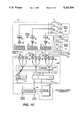
- FIG. 10is a schematic block diagram of the electronics of a CDMA system according to the present invention.
- the functions of the components in FIG. 10are substantially the same as the functions of the components in FIG. 3, except that zone selector 95, which comprises zone switch 92, zone scanner 93, and zone switch/combiner 94, is replaced by a zone selector 582, which comprises a combiner 581.
- zone selector 95which comprises zone switch 92, zone scanner 93, and zone switch/combiner 94
- zone selector 582which comprises a combiner 581.
- the components having the same functions in FIGS. 3 and 8are shown with the same numeral references, and the functions and connections of these components are not described here.
- the CDMA systemshown in FIG. 10, comprises a transmitter module 573 which includes at least one wide-band (spread spectrum) transmitter for generating signals having the appropriate codes at the initiation of a signal from a controller 98.
- the signal generated by module 573are coupled to combiner 581.
- the combined signalis sent to all the zone sites for the antenna set inside the zone site. Unlike the TDMA system, it is not necessary to divide time intervals into time slots and select the appropriate zone sites.
- Signals received by all the zone sitesare also combined by combiner 581.
- signals received by converters 64-65are combined by combiner 581.
- the combined signalis sent to one input port of all the two-branch diversity receivers in a receiver module 575.
- signals received by converters 67-69are combined by combiner 581 and sent to a second input port of all the two-branch diversity receivers in receiver module 575.
- Receiver module 575comprises at least one CDMA receiver, well known in the art, for recovering the signals sent by the mobile units to the master site 514. After the signals coupled to the receivers are diversity combined, they are coupled to controller 98.
Landscapes
- Engineering & Computer Science (AREA)
- Computer Networks & Wireless Communication (AREA)
- Signal Processing (AREA)
- Mobile Radio Communication Systems (AREA)
Abstract
Description
Claims (25)
Priority Applications (11)
| Application Number | Priority Date | Filing Date | Title |
|---|---|---|---|
| US07/679,521US5243598A (en) | 1991-04-02 | 1991-04-02 | Microcell system in digital cellular |
| PCT/US1992/001854WO1992017954A1 (en) | 1991-04-02 | 1992-03-06 | Microcell system in digital cellular |
| EP19920909998EP0578741A4 (en) | 1991-04-02 | 1992-03-06 | MICROCELL SYSTEM IN DIGITAL CELLULAR SYSTEM. |
| JP4509573AJPH06506335A (en) | 1991-04-02 | 1992-03-06 | Digital cellular microcell system |
| US08/263,129US5504936A (en) | 1991-04-02 | 1994-06-21 | Microcells for digital cellular telephone systems |
| US08/330,200US5479397A (en) | 1991-04-02 | 1994-10-27 | CDMA transmission delay method and apparatus |
| US08/608,172US5678186A (en) | 1991-04-02 | 1996-02-28 | Digital microcells for cellular networks |
| US08/873,756US5983118A (en) | 1991-04-02 | 1997-06-12 | Antenna system for a cellular telephone network |
| US09/226,005US6195567B1 (en) | 1991-04-02 | 1999-01-06 | Antenna system for a cellular telephone network |
| US09/713,709US6748216B1 (en) | 1991-04-02 | 2000-11-14 | Method and apparatus for intelligent microcell and antenna selection in digital cellular telephone systems |
| US09/731,324US6434406B2 (en) | 1991-04-02 | 2000-12-05 | Antenna system for a cellular telephone network |
Applications Claiming Priority (1)
| Application Number | Priority Date | Filing Date | Title |
|---|---|---|---|
| US07/679,521US5243598A (en) | 1991-04-02 | 1991-04-02 | Microcell system in digital cellular |
Related Child Applications (1)
| Application Number | Title | Priority Date | Filing Date |
|---|---|---|---|
| US5263693AContinuation-In-Part | 1991-04-02 | 1993-04-26 |
Publications (1)
| Publication Number | Publication Date |
|---|---|
| US5243598Atrue US5243598A (en) | 1993-09-07 |
Family
ID=24727247
Family Applications (1)
| Application Number | Title | Priority Date | Filing Date |
|---|---|---|---|
| US07/679,521Expired - LifetimeUS5243598A (en) | 1991-04-02 | 1991-04-02 | Microcell system in digital cellular |
Country Status (4)
| Country | Link |
|---|---|
| US (1) | US5243598A (en) |
| EP (1) | EP0578741A4 (en) |
| JP (1) | JPH06506335A (en) |
| WO (1) | WO1992017954A1 (en) |
Cited By (147)
| Publication number | Priority date | Publication date | Assignee | Title |
|---|---|---|---|---|
| US5390234A (en)* | 1992-04-20 | 1995-02-14 | International Business Machines Corporation | Dynamic tracking of mobile stations in wireless networks |
| US5390235A (en)* | 1993-06-23 | 1995-02-14 | Pcs Microcell International, Inc. | Cordless telephone system and switching control method therefor |
| US5410538A (en)* | 1993-11-09 | 1995-04-25 | At&T Corp. | Method and apparatus for transmitting signals in a multi-tone code division multiple access communication system |
| US5430789A (en)* | 1992-11-04 | 1995-07-04 | Nec Corporation | Cellular mobile base station apparatus for serving a first and second cell zones |
| US5479397A (en)* | 1991-04-02 | 1995-12-26 | Airtouch Communications Of California | CDMA transmission delay method and apparatus |
| US5513246A (en)* | 1990-12-07 | 1996-04-30 | Telefonaktiebolaget Lm Ericsson | Radiotelephone locating and handoff using alternative criteria |
| US5517503A (en)* | 1993-06-11 | 1996-05-14 | Motorola, Inc. | Apparatus for and method of temporary termination of a communication resource |
| US5524136A (en)* | 1992-04-20 | 1996-06-04 | International Business Machines Corporation | Tracking mobile users in wireless networks |
| US5559808A (en)* | 1995-03-16 | 1996-09-24 | Bell Atlantic Network Services, Inc. | Simulcasting digital video programs |
| US5563892A (en)* | 1995-03-16 | 1996-10-08 | Bell Atlantic Network Services, Inc. | Method of upgrading the program transport capacity of an RF broadcast channel |
| US5579373A (en)* | 1992-11-05 | 1996-11-26 | Samsung Electronics Co., Ltd. | Transmission power control method in cellular radiotelephone system |
| US5586338A (en)* | 1994-12-22 | 1996-12-17 | Bell Atlantic Mobile Systems, Inc. | System identification (SID) list for selecting operating frequencies |
| WO1996042119A1 (en)* | 1995-06-08 | 1996-12-27 | Metawave Communications Corporation | Narrow beam antenna systems with angular diversity |
| US5613204A (en)* | 1994-12-22 | 1997-03-18 | Bell Atlantic Mobile Systems, Inc. | Beacon system for roaming cellular stations |
| US5625876A (en)* | 1993-10-28 | 1997-04-29 | Qualcomm Incorporated | Method and apparatus for performing handoff between sectors of a common base station |
| US5627879A (en)* | 1992-09-17 | 1997-05-06 | Adc Telecommunications, Inc. | Cellular communications system with centralized base stations and distributed antenna units |
| WO1997022218A1 (en)* | 1995-12-11 | 1997-06-19 | Stanford Telecommunications, Inc. | Dma cellular radio system with a channel quality criterion |
| US5659353A (en)* | 1995-03-17 | 1997-08-19 | Bell Atlantic Network Services, Inc. | Television distribution system and method |
| US5666365A (en)* | 1995-03-16 | 1997-09-09 | Bell Atlantic Network Services, Inc. | Simulcast transmission of digital programs to shared antenna receiving systems |
| US5673307A (en)* | 1994-02-17 | 1997-09-30 | Spectralink Corporation | Handoff method for indoor cellular phone system |
| US5701596A (en)* | 1994-12-01 | 1997-12-23 | Radio Frequency Systems, Inc. | Modular interconnect matrix for matrix connection of a plurality of antennas with a plurality of radio channel units |
| US5751707A (en)* | 1995-06-19 | 1998-05-12 | Bell Atlantic Network Services, Inc. | AIN interaction through wireless digital video network |
| US5758287A (en)* | 1994-05-20 | 1998-05-26 | Airtouch Communications, Inc. | Hub and remote cellular telephone system |
| US5761619A (en)* | 1995-03-23 | 1998-06-02 | Telefoanktiebolaget Lm Ericsson | Distributed telecommunications system |
| US5768685A (en)* | 1995-12-11 | 1998-06-16 | Hughes Electronics | Method and apparatus for converting signals in a base station receiver |
| US5781541A (en)* | 1995-05-03 | 1998-07-14 | Bell Atlantic Network Services, Inc. | CDMA system having time-distributed transmission paths for multipath reception |
| US5784683A (en)* | 1995-05-16 | 1998-07-21 | Bell Atlantic Network Services, Inc. | Shared use video processing systems for distributing program signals from multiplexed digitized information signals |
| US5809422A (en)* | 1996-03-08 | 1998-09-15 | Watkins Johnson Company | Distributed microcellular communications system |
| US5822324A (en)* | 1995-03-16 | 1998-10-13 | Bell Atlantic Network Services, Inc. | Simulcasting digital video programs for broadcast and interactive services |
| US5852612A (en)* | 1995-03-16 | 1998-12-22 | Bell Atlantic Network Services, Inc. | Terminal for receiving simulcast digital video programs |
| US5854986A (en)* | 1995-05-19 | 1998-12-29 | Northern Telecom Limited | Cellular communication system having device coupling distribution of antennas to plurality of transceivers |
| US5864760A (en)* | 1993-10-28 | 1999-01-26 | Qualcomm Incorporated | Method and apparatus for reducing the average transmit power from a sectorized base station |
| US5870392A (en)* | 1995-12-28 | 1999-02-09 | Lucent Technologies Inc. | Microcell architecture |
| US5889814A (en)* | 1997-02-24 | 1999-03-30 | At&T Wireless Services, Inc. | Transmit/receive compensation for a dual FDD/TDD architecture |
| US5933787A (en)* | 1995-03-13 | 1999-08-03 | Qualcomm Incorporated | Method and apparatus for performing handoff between sectors of a common base station |
| US5946612A (en)* | 1997-03-28 | 1999-08-31 | Telefonaktiebolaget L M Ericsson (Publ) | Method and apparatus for performing local traffic measurements in a cellular telephone network |
| US5969629A (en)* | 1995-02-06 | 1999-10-19 | Canon Kabushiki Kaisha | Wireless communication apparatus |
| US5987099A (en)* | 1992-10-16 | 1999-11-16 | Northern Telecom Limited | Low-power wireless system for telephone services |
| US6006113A (en)* | 1994-12-01 | 1999-12-21 | Radio Frequency Systems, Inc. | Radio signal scanning and targeting system for use in land mobile radio base sites |
| US6035197A (en)* | 1994-12-29 | 2000-03-07 | Cellco Partnership | Method and system for providing a handoff from a CDMA cellular telephone system |
| US6052599A (en)* | 1997-01-30 | 2000-04-18 | At & T Corp. | Cellular communication system with multiple same frequency broadcasts in a cell |
| US6067455A (en)* | 1991-07-17 | 2000-05-23 | Fujitsu Limited | Digital mobile telephone system having overlay configuration |
| US6078823A (en)* | 1995-11-13 | 2000-06-20 | Interwave Communications International Ltd. | Multiple antenna cellular network |
| US6101400A (en)* | 1997-08-20 | 2000-08-08 | Interwave Communications, Inc. | Methods and apparatus for improved base station transceivers |
| US6112086A (en)* | 1997-02-25 | 2000-08-29 | Adc Telecommunications, Inc. | Scanning RSSI receiver system using inverse fast fourier transforms for a cellular communications system with centralized base stations and distributed antenna units |
| US6115600A (en)* | 1994-12-23 | 2000-09-05 | Nokia Telecommunications Oy. | Method for improving charging criteria in a mobile telephone network |
| US6157668A (en)* | 1993-10-28 | 2000-12-05 | Qualcomm Inc. | Method and apparatus for reducing the average transmit power of a base station |
| US6198925B1 (en) | 1996-08-30 | 2001-03-06 | Cellco Partnership | Method and apparatus for intelligent microcell and antenna selection in digital cellular telephone systems |
| US6243583B1 (en)* | 1992-11-09 | 2001-06-05 | Canon Kabushiki Kaisha | Communication system |
| US6289219B1 (en)* | 1997-06-18 | 2001-09-11 | Nokia Networks Oy | Handover in a base station |
| US20010030956A1 (en)* | 2000-01-07 | 2001-10-18 | Gopal Chillariga | Dynamic channel allocation in multiple-access communication systems |
| US6311074B1 (en)* | 1996-09-17 | 2001-10-30 | Siemens Aktiengesellschaft | Base station and method for covering a cell of a cellular mobile radiotelephone system |
| US6334219B1 (en) | 1994-09-26 | 2001-12-25 | Adc Telecommunications Inc. | Channel selection for a hybrid fiber coax network |
| US6349094B1 (en) | 1997-07-03 | 2002-02-19 | Mdiversity Inc. | Method and apparatus for wireless communications employing control for broadcast transmission |
| US20020085124A1 (en)* | 1999-05-10 | 2002-07-04 | Markus Doetsch | Receiver circuit for a communications terminal and method for processing signals in a receiver circuit |
| US20020105973A1 (en)* | 2001-02-02 | 2002-08-08 | Mitsubishi Wireless Communications, Inc | Systems and methods for improved time slot synchronization using enhanced two-times oversampling |
| EP1235444A4 (en)* | 2000-09-28 | 2003-01-22 | Mitsubishi Electric Corp | RADIO BASE DEVICE AND RADIO COMMUNICATION METHOD |
| US6535721B1 (en)* | 1998-09-30 | 2003-03-18 | Qualcomm Incorporated | Architecture for dependability enhancement of wireless base stations |
| US6549772B1 (en) | 1995-11-13 | 2003-04-15 | Interwave Communications International Ltd. | Multiple antenna cellular network |
| US6580918B1 (en)* | 1997-08-05 | 2003-06-17 | Nokia Mobile Phones Ltd. | Cellular telecommunications system |
| US6611511B1 (en) | 1999-03-04 | 2003-08-26 | Cellco Partnership | Cellular telephone communication system using sector splitting for improved performance |
| US20040106435A1 (en)* | 2002-12-03 | 2004-06-03 | Adc Telecommunications, Inc. | Distributed digital antenna system |
| US6748216B1 (en) | 1991-04-02 | 2004-06-08 | Cellco Partnership | Method and apparatus for intelligent microcell and antenna selection in digital cellular telephone systems |
| US20040132474A1 (en)* | 2000-07-19 | 2004-07-08 | Adc Telecommunications, Inc. | Point-to-multipoint digital radio frequency transport |
| US20040203704A1 (en)* | 2002-06-10 | 2004-10-14 | Andrew Corporation | Indoor wireless voice and data distribution system |
| US20040233871A1 (en)* | 2002-01-18 | 2004-11-25 | Hiroyuki Seki | Feedback control method and apparatus in closed-loop transmit diversity |
| US20050018655A1 (en)* | 1999-04-21 | 2005-01-27 | Opencell, Inc. | Architecture for signal and power distribution in wireless data network |
| US20050018630A1 (en)* | 1999-04-21 | 2005-01-27 | Opencell Corp. | Architecture for signal distribution in wireless data network |
| US20050096061A1 (en)* | 2003-10-30 | 2005-05-05 | Qualcomm Incorporated | Layered reuse for a wireless communication system |
| US20050096062A1 (en)* | 2003-10-30 | 2005-05-05 | Ji Tingfang | Restrictive reuse for a wireless communication system |
| US20050243785A1 (en)* | 2000-03-27 | 2005-11-03 | Opencell Corporation | Multi-protocol distributed wireless system architecture |
| US20060002360A1 (en)* | 2004-06-09 | 2006-01-05 | Ji Tingfang | Dynamic restrictive reuse scheduler |
| US20060172775A1 (en)* | 2005-02-01 | 2006-08-03 | Adc Telecommunications, Inc. | Scalable distributed radio network |
| US20060222054A1 (en)* | 2005-03-31 | 2006-10-05 | Adc Telecommunications, Inc. | Dynamic frequency hopping |
| US20060222020A1 (en)* | 2005-03-31 | 2006-10-05 | Adc Telecommunications, Inc. | Time start in the forward path |
| US20060222087A1 (en)* | 2005-03-31 | 2006-10-05 | Adc Telecommunications, Inc. | Methods and systems for handling underflow and overflow in a software defined radio |
| US20070008939A1 (en)* | 2005-06-10 | 2007-01-11 | Adc Telecommunications, Inc. | Providing wireless coverage into substantially closed environments |
| US20070067763A1 (en)* | 2005-09-19 | 2007-03-22 | Adc Telecommunications, Inc. | Mechanism to upgrade system capability without affecting service |
| US20070071451A1 (en)* | 2005-09-29 | 2007-03-29 | Adc Telecommunications, Inc. | Methods and systems for controlling optical power attenuation |
| US20070071450A1 (en)* | 2005-09-29 | 2007-03-29 | Adc Telecommunications, Inc. | Systems and methods for optical power window control |
| US20070135056A1 (en)* | 2005-12-14 | 2007-06-14 | Adc Telecommunications, Inc. | System and method to monitor broadband radio frequency transport systems |
| US20070147278A1 (en)* | 2002-05-31 | 2007-06-28 | Adc Wireless Solutions Llc | System and method for retransmission of data |
| US20070195905A1 (en)* | 2006-02-21 | 2007-08-23 | Adc Telecommunications, Inc. | Forward error correction in wideband digital RF transport systems |
| US20070238457A1 (en)* | 2006-04-06 | 2007-10-11 | Adc Telecommunications, Inc. | System and method for enhancing the performance of wideband digital RF transport systems |
| US20070243899A1 (en)* | 2006-04-12 | 2007-10-18 | Adc Telecommunications, Inc. | Systems and methods for analog transport of rf voice/data communications |
| US20080014948A1 (en)* | 2006-07-14 | 2008-01-17 | Lgc Wireless, Inc. | System for and method of for providing dedicated capacity in a cellular network |
| US20080058018A1 (en)* | 2006-08-29 | 2008-03-06 | Lgc Wireless, Inc. | Distributed antenna communications system and methods of implementing thereof |
| US20080132273A1 (en)* | 2000-03-29 | 2008-06-05 | Adc Wireless Solutions Llc | Operations and maintenance architecture for multiprotocol distributed system |
| US20080137575A1 (en)* | 2005-03-31 | 2008-06-12 | Adc Telecommunications, Inc. | Dynamic reallocation of bandwidth and modulation protocols |
| US20080151846A1 (en)* | 2006-12-22 | 2008-06-26 | Stefan Scheinert | System for and method of providing remote coverage area for wireless communications |
| US20080168199A1 (en)* | 2005-03-31 | 2008-07-10 | Adc Telecommunications, Inc. | Dynamic readjustment of power |
| US20080181282A1 (en)* | 2007-01-25 | 2008-07-31 | Adc Telecommunications, Inc. | Modular wireless communications platform |
| US20080227441A1 (en)* | 2007-03-12 | 2008-09-18 | Adc Telecommunications, Inc. | Systems and methods for a universal base station |
| US20080232328A1 (en)* | 2007-03-23 | 2008-09-25 | Stefan Scheinert | Localization of a mobile device in distributed antenna communications system |
| US20080242232A1 (en)* | 2007-03-27 | 2008-10-02 | Adc Telecommunications, Inc. | Digitized reverse link monitor |
| US20080240164A1 (en)* | 2007-03-27 | 2008-10-02 | Adc Telecommunications, Inc. | Method for data converter sample clock distribution |
| US20080240225A1 (en)* | 2007-03-27 | 2008-10-02 | Adc Telecommunications, Inc. | Method and system for enhancing the performance of wideband digital rf transport systems |
| US20080254784A1 (en)* | 2005-03-31 | 2008-10-16 | Adc Telecommunications, Inc. | Dynamic reconfiguration of resources through page headers |
| RU2341022C2 (en)* | 2004-06-08 | 2008-12-10 | Квэлкомм Инкорпорейтед | Relaxed service forwarding for return communication line in wireless communication system with frequency reuse |
| US20090005096A1 (en)* | 2007-06-26 | 2009-01-01 | Stefan Scheinert | Distributed antenna communications system |
| US20090046586A1 (en)* | 2007-08-15 | 2009-02-19 | Adc Telecommunications, Inc. | Delay management for distributed communications networks |
| US20090054105A1 (en)* | 2007-08-21 | 2009-02-26 | Adc Telecommunications, Inc. | Method and system for reducing uplink noise in wireless communication systems |
| US20090061940A1 (en)* | 2007-08-31 | 2009-03-05 | Stefan Scheinert | System for and method of configuring distributed antenna communications system |
| US20090082047A1 (en)* | 2007-09-21 | 2009-03-26 | Adc Dsl Systems, Inc. | Auto-discovery in a switch |
| DE19915213B4 (en)* | 1999-04-03 | 2009-05-14 | Robert Bosch Gmbh | Communication system for vehicles, in particular motor vehicles |
| US20090316609A1 (en)* | 2008-06-24 | 2009-12-24 | Lgc Wireless, Inc. | System and method for synchronized time-division duplex signal switching |
| US20100002662A1 (en)* | 2008-02-08 | 2010-01-07 | Adc Telecommunications, Inc. | Enterprise mobile network for providing cellular wireless service using licensed radio frequency spectrum and supporting multiple-device ring for incoming calls |
| US20100002597A1 (en)* | 2004-12-22 | 2010-01-07 | Qualcomm Incorporated | Feedback to support restrictive reuse |
| US20100041341A1 (en)* | 2008-08-18 | 2010-02-18 | Adc Telecommunications, Inc. | Method and apparatus for determining an end of a subframe in a tdd system |
| US20100060433A1 (en)* | 2002-03-14 | 2010-03-11 | Eices Research, Inc. | Systems and/or methods of data acquisition from a transceiver |
| US20100080198A1 (en)* | 2008-09-30 | 2010-04-01 | Adc Telecommunications, Inc. | Internet protocol cellular private branch exchange |
| US20100080214A1 (en)* | 2008-09-30 | 2010-04-01 | Adc Telecommunications, Inc. | Integration of a private cellular system into a unified communications solution |
| US20100135276A1 (en)* | 2008-12-02 | 2010-06-03 | Adc Telecommunications, Inc. | Clock priority chain level systems and methods |
| US20100135674A1 (en)* | 2008-12-02 | 2010-06-03 | Adc Telecommunications, Inc. | Complex optical modulation for real time communication |
| US20100142649A1 (en)* | 2008-12-04 | 2010-06-10 | Adc Telecommunications, Inc. | System and method of generating soft bits |
| US20100178936A1 (en)* | 2009-01-13 | 2010-07-15 | Adc Telecommunications, Inc. | Systems and methods for mobile phone location with digital distributed antenna systems |
| US20100177759A1 (en)* | 2009-01-13 | 2010-07-15 | Adc Telecommunications, Inc. | Systems and methods for ip communication over a distributed antenna system transport |
| US20100177760A1 (en)* | 2009-01-13 | 2010-07-15 | Adc Telecommunications, Inc. | Systems and methods for improved digital rf transport in distributed antenna systems |
| US20100190519A1 (en)* | 2009-01-29 | 2010-07-29 | Adc Telecommunications, Inc. | Method and apparatus for muting a digital link in a distributed antenna system |
| US20100189170A1 (en)* | 2009-01-27 | 2010-07-29 | Adc Telecommunications, Inc. | Method and apparatus for digitally equalizing a signal in a distributed antenna system |
| US20100202356A1 (en)* | 2009-02-12 | 2010-08-12 | Adc Telecommunications, Inc. | Backfire distributed antenna system (das) with delayed transport |
| US20100208777A1 (en)* | 2009-02-17 | 2010-08-19 | Adc Telecommunications, Inc. | Distributed antenna system using gigabit ethernet physical layer device |
| USRE41771E1 (en) | 1995-02-06 | 2010-09-28 | Adc Telecommunications, Inc. | System for multiple use subchannels |
| US7805073B2 (en) | 2006-04-28 | 2010-09-28 | Adc Telecommunications, Inc. | Systems and methods of optical path protection for distributed antenna systems |
| US20100260290A1 (en)* | 2009-04-13 | 2010-10-14 | Adc Telecommunications, Inc. | Smooth modulation switching |
| US20100260281A1 (en)* | 2009-04-13 | 2010-10-14 | Adc Telecommunications, Inc. | Joint channel estimation and modulation detection |
| US20100296458A1 (en)* | 2009-05-19 | 2010-11-25 | Adc Telecommunications, Inc. | Method of inserting cdma beacon pilots in output of distributed remote antenna nodes |
| US20100330955A1 (en)* | 2009-06-26 | 2010-12-30 | Adc Telecommunications, Inc. | Private cellular system with auto-registration functionality |
| USRE42236E1 (en) | 1995-02-06 | 2011-03-22 | Adc Telecommunications, Inc. | Multiuse subcarriers in multipoint-to-point communication using orthogonal frequency division multiplexing |
| US7962111B2 (en) | 2002-02-25 | 2011-06-14 | ADC Wireless, Inc. | Distributed automatic gain control system |
| US8032145B2 (en) | 2004-07-23 | 2011-10-04 | Qualcomm Incorporated | Restrictive reuse set management algorithm for equal grade of service on FL transmission |
| US8462683B2 (en) | 2011-01-12 | 2013-06-11 | Adc Telecommunications, Inc. | Distinct transport path for MIMO transmissions in distributed antenna systems |
| US8472579B2 (en) | 2010-07-28 | 2013-06-25 | Adc Telecommunications, Inc. | Distributed digital reference clock |
| US8532242B2 (en) | 2010-10-27 | 2013-09-10 | Adc Telecommunications, Inc. | Distributed antenna system with combination of both all digital transport and hybrid digital/analog transport |
| US8583100B2 (en) | 2007-01-25 | 2013-11-12 | Adc Telecommunications, Inc. | Distributed remote base station system |
| US8693342B2 (en) | 2011-10-28 | 2014-04-08 | Adc Telecommunications, Inc. | Distributed antenna system using time division duplexing scheme |
| US8743718B2 (en) | 2011-06-21 | 2014-06-03 | Adc Telecommunications, Inc. | End-to-end delay management for distributed communications networks |
| US9178636B2 (en) | 2013-02-22 | 2015-11-03 | Adc Telecommunications, Inc. | Universal remote radio head |
| US9232406B2 (en) | 2002-03-14 | 2016-01-05 | Odyssey Wireless, Inc. | Systems and/or methods of data acquisition from a transceiver |
| US9450689B2 (en) | 2013-10-07 | 2016-09-20 | Commscope Technologies Llc | Systems and methods for delay management in distributed antenna system with direct digital interface to base station |
| US9577922B2 (en) | 2014-02-18 | 2017-02-21 | Commscope Technologies Llc | Selectively combining uplink signals in distributed antenna systems |
| US9596322B2 (en) | 2014-06-11 | 2017-03-14 | Commscope Technologies Llc | Bitrate efficient transport through distributed antenna systems |
| US9787457B2 (en) | 2013-10-07 | 2017-10-10 | Commscope Technologies Llc | Systems and methods for integrating asynchronous signals in distributed antenna system with direct digital interface to base station |
| US10020850B2 (en) | 2013-02-22 | 2018-07-10 | Commscope Technologies Llc | Master reference for base station network interface sourced from distributed antenna system |
| USRE47466E1 (en) | 2009-01-13 | 2019-06-25 | Commscope Technologies Llc | Systems and methods for IP communication over a distributed antenna system transport |
| US10499269B2 (en) | 2015-11-12 | 2019-12-03 | Commscope Technologies Llc | Systems and methods for assigning controlled nodes to channel interfaces of a controller |
| USRE49644E1 (en) | 2002-03-14 | 2023-09-05 | Odyssey Wireless, Inc. | Systems and/or methods of data acquisition from a transceiver |
Families Citing this family (7)
| Publication number | Priority date | Publication date | Assignee | Title |
|---|---|---|---|---|
| AU731179B2 (en)* | 1993-09-21 | 2001-03-22 | Telstra Corporation Limited | A base station for a mobile telecommunications system |
| AU684451B3 (en)* | 1993-09-21 | 1997-11-13 | Telstra Corporation Limited | A base station for a mobile telecommunications system |
| US5839071A (en)* | 1993-09-21 | 1998-11-17 | Telstra Corporation Limited | Base station for a mobile telecommunications system |
| JP2576388B2 (en)* | 1993-11-08 | 1997-01-29 | 日本電気株式会社 | Base station transceiver |
| AUPM780994A0 (en)* | 1994-08-31 | 1994-09-22 | Telstra Corporation Limited | A method and apparatus for channel allocation in a cellular telecommunications network |
| JP3076252B2 (en)* | 1996-11-25 | 2000-08-14 | 日本電気株式会社 | Multi-sector switching control device in cellular mobile communication system |
| US6480472B1 (en) | 1999-07-21 | 2002-11-12 | Qualcomm Incorporated | Mobile station supervision of the forward dedicated control channel when in the discontinuous transmission mode |
Citations (3)
| Publication number | Priority date | Publication date | Assignee | Title |
|---|---|---|---|---|
| US4785450A (en)* | 1987-08-06 | 1988-11-15 | International Mobile Machines Corporation | Apparatus and method for obtaining frequency agility in digital communication systems |
| US4797947A (en)* | 1987-05-01 | 1989-01-10 | Motorola, Inc. | Microcellular communications system using macrodiversity |
| US4932049A (en)* | 1989-02-06 | 1990-06-05 | Pactel Corporation | Cellular telephone system |
Family Cites Families (5)
| Publication number | Priority date | Publication date | Assignee | Title |
|---|---|---|---|---|
| US4901307A (en)* | 1986-10-17 | 1990-02-13 | Qualcomm, Inc. | Spread spectrum multiple access communication system using satellite or terrestrial repeaters |
| US4866710A (en)* | 1988-02-22 | 1989-09-12 | Motorola, Inc. | Reuse groups for scan monitoring in digital cellular systems |
| US5097484A (en)* | 1988-10-12 | 1992-03-17 | Sumitomo Electric Industries, Ltd. | Diversity transmission and reception method and equipment |
| GB8826476D0 (en)* | 1988-11-11 | 1988-12-14 | British Telecomm | Communications system |
| IL100213A (en)* | 1990-12-07 | 1995-03-30 | Qualcomm Inc | CDMA microcellular telephone system and distributed antenna system therefor |
- 1991
- 1991-04-02USUS07/679,521patent/US5243598A/ennot_activeExpired - Lifetime
- 1992
- 1992-03-06EPEP19920909998patent/EP0578741A4/ennot_activeWithdrawn
- 1992-03-06JPJP4509573Apatent/JPH06506335A/enactivePending
- 1992-03-06WOPCT/US1992/001854patent/WO1992017954A1/ennot_activeApplication Discontinuation
Patent Citations (4)
| Publication number | Priority date | Publication date | Assignee | Title |
|---|---|---|---|---|
| US4797947A (en)* | 1987-05-01 | 1989-01-10 | Motorola, Inc. | Microcellular communications system using macrodiversity |
| US4785450A (en)* | 1987-08-06 | 1988-11-15 | International Mobile Machines Corporation | Apparatus and method for obtaining frequency agility in digital communication systems |
| US4785450B1 (en)* | 1987-08-06 | 1999-10-12 | Interdigital Tech Corp | Apparatus and method for obtaining frequency agility in digital communication system |
| US4932049A (en)* | 1989-02-06 | 1990-06-05 | Pactel Corporation | Cellular telephone system |
Cited By (338)
| Publication number | Priority date | Publication date | Assignee | Title |
|---|---|---|---|---|
| US5513246A (en)* | 1990-12-07 | 1996-04-30 | Telefonaktiebolaget Lm Ericsson | Radiotelephone locating and handoff using alternative criteria |
| US6748216B1 (en) | 1991-04-02 | 2004-06-08 | Cellco Partnership | Method and apparatus for intelligent microcell and antenna selection in digital cellular telephone systems |
| US5678186A (en)* | 1991-04-02 | 1997-10-14 | Airtouch Communications, Inc. | Digital microcells for cellular networks |
| US5479397A (en)* | 1991-04-02 | 1995-12-26 | Airtouch Communications Of California | CDMA transmission delay method and apparatus |
| US5504936A (en)* | 1991-04-02 | 1996-04-02 | Airtouch Communications Of California | Microcells for digital cellular telephone systems |
| US6434406B2 (en) | 1991-04-02 | 2002-08-13 | Cellco Partnership | Antenna system for a cellular telephone network |
| US5983118A (en)* | 1991-04-02 | 1999-11-09 | Airtouch Communications, Inc. | Antenna system for a cellular telephone network |
| US6067455A (en)* | 1991-07-17 | 2000-05-23 | Fujitsu Limited | Digital mobile telephone system having overlay configuration |
| US5390234A (en)* | 1992-04-20 | 1995-02-14 | International Business Machines Corporation | Dynamic tracking of mobile stations in wireless networks |
| US5524136A (en)* | 1992-04-20 | 1996-06-04 | International Business Machines Corporation | Tracking mobile users in wireless networks |
| USRE43964E1 (en) | 1992-09-17 | 2013-02-05 | Adc Telecommunications, Inc. | Cellular communications system with sectorization |
| US5644622A (en)* | 1992-09-17 | 1997-07-01 | Adc Telecommunications, Inc. | Cellular communications system with centralized base stations and distributed antenna units |
| US5657374A (en)* | 1992-09-17 | 1997-08-12 | Adc Telecommunications, Inc. | Cellular communications system with centralized base stations and distributed antenna units |
| USRE45321E1 (en) | 1992-09-17 | 2015-01-06 | Adc Telecommunications, Inc. | Cellular communications system with sectorization |
| US5642405A (en)* | 1992-09-17 | 1997-06-24 | Adc Telecommunications, Inc. | Cellular communications system with centralized base stations and distributed antenna units |
| US5852651A (en)* | 1992-09-17 | 1998-12-22 | Adc Telecommunications, Inc. | Cellular communications system with sectorization |
| USRE40564E1 (en) | 1992-09-17 | 2008-11-04 | Adc Telecommunications, Inc. | Cellular communications system with sectorization |
| US5627879A (en)* | 1992-09-17 | 1997-05-06 | Adc Telecommunications, Inc. | Cellular communications system with centralized base stations and distributed antenna units |
| US5987099A (en)* | 1992-10-16 | 1999-11-16 | Northern Telecom Limited | Low-power wireless system for telephone services |
| US5430789A (en)* | 1992-11-04 | 1995-07-04 | Nec Corporation | Cellular mobile base station apparatus for serving a first and second cell zones |
| US5579373A (en)* | 1992-11-05 | 1996-11-26 | Samsung Electronics Co., Ltd. | Transmission power control method in cellular radiotelephone system |
| US6243583B1 (en)* | 1992-11-09 | 2001-06-05 | Canon Kabushiki Kaisha | Communication system |
| US5517503A (en)* | 1993-06-11 | 1996-05-14 | Motorola, Inc. | Apparatus for and method of temporary termination of a communication resource |
| US5390235A (en)* | 1993-06-23 | 1995-02-14 | Pcs Microcell International, Inc. | Cordless telephone system and switching control method therefor |
| US5625876A (en)* | 1993-10-28 | 1997-04-29 | Qualcomm Incorporated | Method and apparatus for performing handoff between sectors of a common base station |
| US6546058B1 (en)* | 1993-10-28 | 2003-04-08 | Qualcomm Incorporated | Method and apparatus for reducing the average transmit power of a base station |
| US6157668A (en)* | 1993-10-28 | 2000-12-05 | Qualcomm Inc. | Method and apparatus for reducing the average transmit power of a base station |
| CN1065104C (en)* | 1993-10-28 | 2001-04-25 | 夸尔柯姆股份有限公司 | Method and apparatus for reducing the average downlink transmitted power from base stations during soft handoff |
| US5864760A (en)* | 1993-10-28 | 1999-01-26 | Qualcomm Incorporated | Method and apparatus for reducing the average transmit power from a sectorized base station |
| US5410538A (en)* | 1993-11-09 | 1995-04-25 | At&T Corp. | Method and apparatus for transmitting signals in a multi-tone code division multiple access communication system |
| US5673307A (en)* | 1994-02-17 | 1997-09-30 | Spectralink Corporation | Handoff method for indoor cellular phone system |
| US5758287A (en)* | 1994-05-20 | 1998-05-26 | Airtouch Communications, Inc. | Hub and remote cellular telephone system |
| US8638655B2 (en) | 1994-09-26 | 2014-01-28 | Htc Corporation | Systems and method for orthogonal frequency divisional multiplexing |
| USRE44460E1 (en) | 1994-09-26 | 2013-08-27 | Htc Corporation | Systems for synchronous multipoint-to-point orthogonal frequency division multiplexing communication |
| US6334219B1 (en) | 1994-09-26 | 2001-12-25 | Adc Telecommunications Inc. | Channel selection for a hybrid fiber coax network |
| US8547824B2 (en) | 1994-09-26 | 2013-10-01 | Htc Corporation | Systems and methods for orthogonal frequency divisional multiplexing |
| US6418558B1 (en) | 1994-09-26 | 2002-07-09 | Adc Telecommunications, Inc. | Hybrid fiber/coax video and telephony communication |
| US5701596A (en)* | 1994-12-01 | 1997-12-23 | Radio Frequency Systems, Inc. | Modular interconnect matrix for matrix connection of a plurality of antennas with a plurality of radio channel units |
| US5752200A (en)* | 1994-12-01 | 1998-05-12 | Radio Frequency Systems, Inc. | Modular interconnect matrix for matrix connection of a plurality of antennas with a plurality of radio channel units |
| US6006113A (en)* | 1994-12-01 | 1999-12-21 | Radio Frequency Systems, Inc. | Radio signal scanning and targeting system for use in land mobile radio base sites |
| US5613204A (en)* | 1994-12-22 | 1997-03-18 | Bell Atlantic Mobile Systems, Inc. | Beacon system for roaming cellular stations |
| US5586338A (en)* | 1994-12-22 | 1996-12-17 | Bell Atlantic Mobile Systems, Inc. | System identification (SID) list for selecting operating frequencies |
| US6115600A (en)* | 1994-12-23 | 2000-09-05 | Nokia Telecommunications Oy. | Method for improving charging criteria in a mobile telephone network |
| US6035197A (en)* | 1994-12-29 | 2000-03-07 | Cellco Partnership | Method and system for providing a handoff from a CDMA cellular telephone system |
| US6240292B1 (en) | 1994-12-29 | 2001-05-29 | Cellco Partnership | Method and system for providing a handoff from a CDMA cellular telephone system |
| US8174956B2 (en) | 1995-02-06 | 2012-05-08 | Htc Corporation | Systems and method for orthogonal frequency divisional multiplexing |
| US7872985B2 (en) | 1995-02-06 | 2011-01-18 | Adc Dsl Systems, Inc. | System for multi-frame alignment |
| US7535822B2 (en) | 1995-02-06 | 2009-05-19 | Adc Telecommunications, Inc. | Synchronization of remote units for a communication network |
| US5969629A (en)* | 1995-02-06 | 1999-10-19 | Canon Kabushiki Kaisha | Wireless communication apparatus |
| US7773537B2 (en) | 1995-02-06 | 2010-08-10 | Adc Telecommunications, Inc. | Ranging and round trip delay timing adjustment in a multi-point to point bidirectional communication system |
| USRE42236E1 (en) | 1995-02-06 | 2011-03-22 | Adc Telecommunications, Inc. | Multiuse subcarriers in multipoint-to-point communication using orthogonal frequency division multiplexing |
| US7995454B2 (en) | 1995-02-06 | 2011-08-09 | Htc Corporation | Systems and method for orthogonal frequency divisional multiplexing |
| US7756060B2 (en) | 1995-02-06 | 2010-07-13 | Adc Telecommunications, Inc. | Tone allocation in multipoint-to-point communication using orthogonal frequency division multiplexing |
| US7936662B2 (en) | 1995-02-06 | 2011-05-03 | Adc Telecommunications, Inc. | Ranging and round trip delay timing adjustment in a multi-point to point bidirectional communication system |
| US8089853B2 (en) | 1995-02-06 | 2012-01-03 | Htc Corporation | Systems and method for orthogonal frequency divisional multiplexing |
| US8406115B2 (en) | 1995-02-06 | 2013-03-26 | Htc Corporation | Systems and methods for orthogonal frequency division multiplexing |
| US7983141B2 (en) | 1995-02-06 | 2011-07-19 | Geile Michael J | Synchronized multipoint-to-point communication using orthogonal frequency division |
| US7881180B2 (en) | 1995-02-06 | 2011-02-01 | Adc Telecommunications, Inc. | Systems and method for orthogonal frequency divisional multiplexing |
| US7912138B2 (en) | 1995-02-06 | 2011-03-22 | Adc Telecommunications, Inc. | Timing and symbol alignment in multipoint-to-point communication using orthogonal frequency division multiplexing |
| US7706349B2 (en) | 1995-02-06 | 2010-04-27 | Adc Telecommunications, Inc. | Methods and systems for selecting modulation in an orthogonal frequency division multiplexing system |
| US7697453B2 (en) | 1995-02-06 | 2010-04-13 | Adc Telecommunications, Inc. | Synchronization techniques in multipoint-to-point communication using orthogonal frequency division multiplexing |
| US7672219B2 (en) | 1995-02-06 | 2010-03-02 | Adc Telecommunications, Inc. | Multipoint-to-point communication using orthogonal frequency division multiplexing |
| US7881181B2 (en) | 1995-02-06 | 2011-02-01 | Adc Telecommunications, Inc. | Systems and method for orthogonal frequency divisional multiplexing |
| US8351321B2 (en) | 1995-02-06 | 2013-01-08 | Htc Corporation | Systems and method for orthogonal frequency divisional multiplexing |
| US7675843B2 (en) | 1995-02-06 | 2010-03-09 | Adc Telecommunications, Inc. | Multipoint-to-point communication using orthogonal frequency division multiplexing |
| US8315150B2 (en) | 1995-02-06 | 2012-11-20 | Htc Corporation | Synchronized multipoint-to-point communication using orthogonal frequency division |
| US8576693B2 (en) | 1995-02-06 | 2013-11-05 | Htc Corporation | Systems and method for orthogonal frequency division multiplexing |
| US8199632B2 (en) | 1995-02-06 | 2012-06-12 | Htc Corporation | Systems and method for orthogonal frequency divisional multiplexing |
| US8213399B2 (en) | 1995-02-06 | 2012-07-03 | Htc Corporation | System for multiple use subchannels |
| US8213398B2 (en) | 1995-02-06 | 2012-07-03 | Htc Corporation | Method for multiple use subchannels |
| US7957265B2 (en) | 1995-02-06 | 2011-06-07 | Adc Telecommunications, Inc. | Systems and method for orthogonal frequency divisional multiplexing |
| USRE41771E1 (en) | 1995-02-06 | 2010-09-28 | Adc Telecommunications, Inc. | System for multiple use subchannels |
| US5933787A (en)* | 1995-03-13 | 1999-08-03 | Qualcomm Incorporated | Method and apparatus for performing handoff between sectors of a common base station |
| US5563892A (en)* | 1995-03-16 | 1996-10-08 | Bell Atlantic Network Services, Inc. | Method of upgrading the program transport capacity of an RF broadcast channel |
| US5852612A (en)* | 1995-03-16 | 1998-12-22 | Bell Atlantic Network Services, Inc. | Terminal for receiving simulcast digital video programs |
| US5651010A (en)* | 1995-03-16 | 1997-07-22 | Bell Atlantic Network Services, Inc. | Simultaneous overlapping broadcasting of digital programs |
| US5646942A (en)* | 1995-03-16 | 1997-07-08 | Bell Atlantic Network Services, Inc. | Simulcast transmission of digital programs to shared antenna receiving systems |
| US5666365A (en)* | 1995-03-16 | 1997-09-09 | Bell Atlantic Network Services, Inc. | Simulcast transmission of digital programs to shared antenna receiving systems |
| US5610916A (en)* | 1995-03-16 | 1997-03-11 | Bell Atlantic Network Services, Inc. | Shared receiving systems utilizing telephone cables as video drops |
| US5559808A (en)* | 1995-03-16 | 1996-09-24 | Bell Atlantic Network Services, Inc. | Simulcasting digital video programs |
| US5822324A (en)* | 1995-03-16 | 1998-10-13 | Bell Atlantic Network Services, Inc. | Simulcasting digital video programs for broadcast and interactive services |
| US5729549A (en)* | 1995-03-16 | 1998-03-17 | Bell Atlantic Network Services, Inc. | Simulcasting digital video programs for broadcast and interactive services |
| US6130898A (en)* | 1995-03-16 | 2000-10-10 | Bell Atlantic Network Services, Inc. | Simulcasting digital video programs for broadcast and interactive services |
| US5659353A (en)* | 1995-03-17 | 1997-08-19 | Bell Atlantic Network Services, Inc. | Television distribution system and method |
| US5729825A (en)* | 1995-03-17 | 1998-03-17 | Bell Atlantic Network Services, Inc. | Television distribution system and method using transmitting antennas on peripheries of adjacent cells within a service area |
| US6005605A (en)* | 1995-03-17 | 1999-12-21 | Bell Atlantic Network Services, Inc. | Television distribution system and method |
| US5761619A (en)* | 1995-03-23 | 1998-06-02 | Telefoanktiebolaget Lm Ericsson | Distributed telecommunications system |
| US5781541A (en)* | 1995-05-03 | 1998-07-14 | Bell Atlantic Network Services, Inc. | CDMA system having time-distributed transmission paths for multipath reception |
| US5784683A (en)* | 1995-05-16 | 1998-07-21 | Bell Atlantic Network Services, Inc. | Shared use video processing systems for distributing program signals from multiplexed digitized information signals |
| US5854986A (en)* | 1995-05-19 | 1998-12-29 | Northern Telecom Limited | Cellular communication system having device coupling distribution of antennas to plurality of transceivers |
| WO1996042119A1 (en)* | 1995-06-08 | 1996-12-27 | Metawave Communications Corporation | Narrow beam antenna systems with angular diversity |
| US5751707A (en)* | 1995-06-19 | 1998-05-12 | Bell Atlantic Network Services, Inc. | AIN interaction through wireless digital video network |
| US6078823A (en)* | 1995-11-13 | 2000-06-20 | Interwave Communications International Ltd. | Multiple antenna cellular network |
| US6549772B1 (en) | 1995-11-13 | 2003-04-15 | Interwave Communications International Ltd. | Multiple antenna cellular network |
| US6301482B1 (en)* | 1995-12-11 | 2001-10-09 | Stanford Telecommunications, Inc. | DMA cellular radio system with a channel quality criterion |
| US6415131B1 (en)* | 1995-12-11 | 2002-07-02 | Stanford Telecommunications, Inc. | DMA cellular radio system with a channel quality criterion |
| US5768685A (en)* | 1995-12-11 | 1998-06-16 | Hughes Electronics | Method and apparatus for converting signals in a base station receiver |
| WO1997022218A1 (en)* | 1995-12-11 | 1997-06-19 | Stanford Telecommunications, Inc. | Dma cellular radio system with a channel quality criterion |
| US5870392A (en)* | 1995-12-28 | 1999-02-09 | Lucent Technologies Inc. | Microcell architecture |
| US5809422A (en)* | 1996-03-08 | 1998-09-15 | Watkins Johnson Company | Distributed microcellular communications system |
| US7310522B2 (en) | 1996-05-20 | 2007-12-18 | Adc Telecommunications, Inc. | Systems for synchronous multipoint-to-point orthogonal frequency division multiplexing communication |
| US6198925B1 (en) | 1996-08-30 | 2001-03-06 | Cellco Partnership | Method and apparatus for intelligent microcell and antenna selection in digital cellular telephone systems |
| US6311074B1 (en)* | 1996-09-17 | 2001-10-30 | Siemens Aktiengesellschaft | Base station and method for covering a cell of a cellular mobile radiotelephone system |
| US6052599A (en)* | 1997-01-30 | 2000-04-18 | At & T Corp. | Cellular communication system with multiple same frequency broadcasts in a cell |
| US5889814A (en)* | 1997-02-24 | 1999-03-30 | At&T Wireless Services, Inc. | Transmit/receive compensation for a dual FDD/TDD architecture |
| US6112086A (en)* | 1997-02-25 | 2000-08-29 | Adc Telecommunications, Inc. | Scanning RSSI receiver system using inverse fast fourier transforms for a cellular communications system with centralized base stations and distributed antenna units |
| US6836660B1 (en) | 1997-02-25 | 2004-12-28 | Adc Tolocommunications, Inc. And Adc Mobile Systems, Inc. | Methods and systems for communicating in a cellular network |
| US5946612A (en)* | 1997-03-28 | 1999-08-31 | Telefonaktiebolaget L M Ericsson (Publ) | Method and apparatus for performing local traffic measurements in a cellular telephone network |
| US6289219B1 (en)* | 1997-06-18 | 2001-09-11 | Nokia Networks Oy | Handover in a base station |
| US6349094B1 (en) | 1997-07-03 | 2002-02-19 | Mdiversity Inc. | Method and apparatus for wireless communications employing control for broadcast transmission |
| US6580918B1 (en)* | 1997-08-05 | 2003-06-17 | Nokia Mobile Phones Ltd. | Cellular telecommunications system |
| US6101400A (en)* | 1997-08-20 | 2000-08-08 | Interwave Communications, Inc. | Methods and apparatus for improved base station transceivers |
| US6535721B1 (en)* | 1998-09-30 | 2003-03-18 | Qualcomm Incorporated | Architecture for dependability enhancement of wireless base stations |
| US6611511B1 (en) | 1999-03-04 | 2003-08-26 | Cellco Partnership | Cellular telephone communication system using sector splitting for improved performance |
| DE19915213B4 (en)* | 1999-04-03 | 2009-05-14 | Robert Bosch Gmbh | Communication system for vehicles, in particular motor vehicles |
| US20050018630A1 (en)* | 1999-04-21 | 2005-01-27 | Opencell Corp. | Architecture for signal distribution in wireless data network |
| US7969965B2 (en) | 1999-04-21 | 2011-06-28 | Lgc Wireless, Inc. | Architecture for signal and power distribution in wireless data network |
| US9674678B2 (en) | 1999-04-21 | 2017-06-06 | Commscope Technologies Llc | Architecture for signal and power distribution in wireless data network |
| US20050018655A1 (en)* | 1999-04-21 | 2005-01-27 | Opencell, Inc. | Architecture for signal and power distribution in wireless data network |
| US8379569B2 (en) | 1999-04-21 | 2013-02-19 | Adc Telecommunications, Inc. | Architecture for signal distribution in wireless data network |
| US20110216751A1 (en)* | 1999-04-21 | 2011-09-08 | Lgc Wireless, Inc. | Architecture for signal and power distribution in wireless data network |
| US10142813B2 (en) | 1999-04-21 | 2018-11-27 | Commscope Technologies Llc | Architecture for signal and power distribution in wireless data network |
| US8824457B2 (en) | 1999-04-21 | 2014-09-02 | Adc Telecommunications, Inc. | Architecture for signal and power distribution in wireless data network |
| US7139341B2 (en) | 1999-05-10 | 2006-11-21 | Infineon Technologies Ag | Receiver circuit for a communications terminal and method for processing signals in a receiver circuit |
| US20020085124A1 (en)* | 1999-05-10 | 2002-07-04 | Markus Doetsch | Receiver circuit for a communications terminal and method for processing signals in a receiver circuit |
| US20010030956A1 (en)* | 2000-01-07 | 2001-10-18 | Gopal Chillariga | Dynamic channel allocation in multiple-access communication systems |
| US7177298B2 (en) | 2000-01-07 | 2007-02-13 | Gopal Chillariga | Dynamic channel allocation in multiple-access communication systems |
| US20070042786A1 (en)* | 2000-01-07 | 2007-02-22 | Northstar Acquisitions, Llc | Dynamic channel allocation in multiple-access communication systems |
| US7643423B2 (en) | 2000-01-07 | 2010-01-05 | Gopal Chillariga | Dynamic channel allocation in multiple-access communication systems |
| US8290483B2 (en) | 2000-03-27 | 2012-10-16 | Adc Telecommunications, Inc. | Multiprotocol antenna system for multiple service provider-multiple air interface co-located base stations |
| US10321328B2 (en) | 2000-03-27 | 2019-06-11 | Commscope Technologies Llc | Multiprotocol antenna system for multiple service providers |
| US7920858B2 (en) | 2000-03-27 | 2011-04-05 | Lgc Wireless, Inc. | Multiprotocol antenna system for multiple service provider-multiple air interface co-located base stations |
| US7761093B2 (en) | 2000-03-27 | 2010-07-20 | Adc Wireless Solutions Llc | Multi-protocol distributed antenna system for multiple service provider-multiple air interface co-located base stations |
| US20110143649A1 (en)* | 2000-03-27 | 2011-06-16 | Lgc Wireless, Inc. | Multiprotocol antenna system for multiple service provider-multiple air interface co-located base stations |
| US20050243785A1 (en)* | 2000-03-27 | 2005-11-03 | Opencell Corporation | Multi-protocol distributed wireless system architecture |
| US8559939B2 (en) | 2000-03-27 | 2013-10-15 | Adc Telecommunications, Inc. | Multiprotocol antenna system for multiple service provider-multiple air interface co-located base stations |
| US8160570B2 (en) | 2000-03-27 | 2012-04-17 | Lgc Wireless, Llc | Multiprotocol antenna system for multiple service provider-multiple air interface co-located base stations |
| US20100255855A1 (en)* | 2000-03-27 | 2010-10-07 | Lgc Wireless, Inc. | Multiprotocol antenna system for multiple service provider-multiple air interface co-located base stations |
| US9867052B2 (en) | 2000-03-27 | 2018-01-09 | Commscope Technologies Llc | Multiprotocol antenna system for multiple service providers |
| US20080132273A1 (en)* | 2000-03-29 | 2008-06-05 | Adc Wireless Solutions Llc | Operations and maintenance architecture for multiprotocol distributed system |
| US8762510B2 (en) | 2000-03-29 | 2014-06-24 | Adc Telecommunications, Inc. | Operations and maintenance architecture for multiprotocol distributed system |
| US7991903B2 (en) | 2000-03-29 | 2011-08-02 | Lgc Wireless, Inc. | Operations and maintenance architecture for multiprotocol distributed system |
| US9668142B2 (en) | 2000-03-29 | 2017-05-30 | Commscope Technologies Llc | Operations and maintenance architecture for multiprotocol distributed system |
| US10505635B2 (en) | 2000-07-19 | 2019-12-10 | Commscope Technologies Llc | Point-to-multipoint digital radio frequency transport |
| US20100061291A1 (en)* | 2000-07-19 | 2010-03-11 | Adc Telecommunications, Inc. | Point-to-multipoint digital radio frequency transport |
| US7639982B2 (en) | 2000-07-19 | 2009-12-29 | Adc Telecommunications, Inc. | Point-to-multipoint digital radio frequency transport |
| US20040132474A1 (en)* | 2000-07-19 | 2004-07-08 | Adc Telecommunications, Inc. | Point-to-multipoint digital radio frequency transport |
| US8326218B2 (en) | 2000-07-19 | 2012-12-04 | Adc Telecommunications, Inc. | Point-to-multipoint digital radio frequency transport |
| US9332402B2 (en) | 2000-07-19 | 2016-05-03 | Commscope Technologies Llc | Point-to-multipoint digital radio frequency transport |
| US10498434B2 (en) | 2000-07-19 | 2019-12-03 | CommScope Technolgies LLC | Point-to-multipoint digital radio frequency transport |
| US8577286B2 (en) | 2000-07-19 | 2013-11-05 | Adc Telecommunications, Inc. | Point-to-multipoint digital radio frequency transport |
| US6947769B1 (en) | 2000-09-28 | 2005-09-20 | Mitsubishi Denki Kabushiki Kaisha | Radio base station device and radio communication method |
| EP1235444A4 (en)* | 2000-09-28 | 2003-01-22 | Mitsubishi Electric Corp | RADIO BASE DEVICE AND RADIO COMMUNICATION METHOD |
| US20020105973A1 (en)* | 2001-02-02 | 2002-08-08 | Mitsubishi Wireless Communications, Inc | Systems and methods for improved time slot synchronization using enhanced two-times oversampling |
| US20040233871A1 (en)* | 2002-01-18 | 2004-11-25 | Hiroyuki Seki | Feedback control method and apparatus in closed-loop transmit diversity |
| US7924784B2 (en) | 2002-01-18 | 2011-04-12 | Fujitsu Limited | Feedback control method and apparatus in closed-loop transmit diversity |
| US7962111B2 (en) | 2002-02-25 | 2011-06-14 | ADC Wireless, Inc. | Distributed automatic gain control system |
| US8970351B2 (en) | 2002-03-14 | 2015-03-03 | Eices Research, Inc. | Systems and/or methods of data acquisition from a transceiver |
| USRE49644E1 (en) | 2002-03-14 | 2023-09-05 | Odyssey Wireless, Inc. | Systems and/or methods of data acquisition from a transceiver |
| US20100060433A1 (en)* | 2002-03-14 | 2010-03-11 | Eices Research, Inc. | Systems and/or methods of data acquisition from a transceiver |
| US8665068B2 (en) | 2002-03-14 | 2014-03-04 | Eices Research, Inc. | Systems and/or methods of data acquisition from a transceiver |
| USRE48562E1 (en) | 2002-03-14 | 2021-05-18 | Odyssey Wireless, Inc. | Systems and/or methods of data acquisition from a transceiver |
| US9232406B2 (en) | 2002-03-14 | 2016-01-05 | Odyssey Wireless, Inc. | Systems and/or methods of data acquisition from a transceiver |
| USRE47408E1 (en) | 2002-03-14 | 2019-05-28 | Odyssey Wireless, Inc. | Systems and/or methods of data acquisition from a transceiver |
| US20070147278A1 (en)* | 2002-05-31 | 2007-06-28 | Adc Wireless Solutions Llc | System and method for retransmission of data |
| US7702985B2 (en) | 2002-05-31 | 2010-04-20 | Adc Wireless Solutions Llc | System and method for retransmission of data |
| US7263293B2 (en) | 2002-06-10 | 2007-08-28 | Andrew Corporation | Indoor wireless voice and data distribution system |
| US20040203704A1 (en)* | 2002-06-10 | 2004-10-14 | Andrew Corporation | Indoor wireless voice and data distribution system |
| US20040106435A1 (en)* | 2002-12-03 | 2004-06-03 | Adc Telecommunications, Inc. | Distributed digital antenna system |
| USRE50112E1 (en) | 2002-12-03 | 2024-09-03 | Outdoor Wireless Networks LLC | Distributed digital antenna system |
| USRE49377E1 (en) | 2002-12-03 | 2023-01-17 | Commscope Technologies Llc | Distributed digital antenna system |
| US8958789B2 (en) | 2002-12-03 | 2015-02-17 | Adc Telecommunications, Inc. | Distributed digital antenna system |
| US20050096061A1 (en)* | 2003-10-30 | 2005-05-05 | Qualcomm Incorporated | Layered reuse for a wireless communication system |
| US8526963B2 (en) | 2003-10-30 | 2013-09-03 | Qualcomm Incorporated | Restrictive reuse for a wireless communication system |
| US20050096062A1 (en)* | 2003-10-30 | 2005-05-05 | Ji Tingfang | Restrictive reuse for a wireless communication system |
| US8483691B2 (en)* | 2003-10-30 | 2013-07-09 | Qualcomm Incorporated | Restrictive reuse for a wireless communication system |
| US9585023B2 (en) | 2003-10-30 | 2017-02-28 | Qualcomm Incorporated | Layered reuse for a wireless communication system |
| US20080253319A1 (en)* | 2003-10-30 | 2008-10-16 | Qualcomm Incorporated | Restrictive reuse for a wireless communication system |
| RU2341022C2 (en)* | 2004-06-08 | 2008-12-10 | Квэлкомм Инкорпорейтед | Relaxed service forwarding for return communication line in wireless communication system with frequency reuse |
| US8059589B2 (en) | 2004-06-09 | 2011-11-15 | Qualcomm Incorporated | Dynamic restrictive reuse scheduler |
| US20060002360A1 (en)* | 2004-06-09 | 2006-01-05 | Ji Tingfang | Dynamic restrictive reuse scheduler |
| US8032145B2 (en) | 2004-07-23 | 2011-10-04 | Qualcomm Incorporated | Restrictive reuse set management algorithm for equal grade of service on FL transmission |
| US8675509B2 (en) | 2004-12-22 | 2014-03-18 | Qualcomm Incorporated | Feedback to support restrictive reuse |
| US20100002597A1 (en)* | 2004-12-22 | 2010-01-07 | Qualcomm Incorporated | Feedback to support restrictive reuse |
| US7787854B2 (en) | 2005-02-01 | 2010-08-31 | Adc Telecommunications, Inc. | Scalable distributed radio network |
| US20060172775A1 (en)* | 2005-02-01 | 2006-08-03 | Adc Telecommunications, Inc. | Scalable distributed radio network |
| US20080254784A1 (en)* | 2005-03-31 | 2008-10-16 | Adc Telecommunications, Inc. | Dynamic reconfiguration of resources through page headers |
| US20060222020A1 (en)* | 2005-03-31 | 2006-10-05 | Adc Telecommunications, Inc. | Time start in the forward path |
| US20080168199A1 (en)* | 2005-03-31 | 2008-07-10 | Adc Telecommunications, Inc. | Dynamic readjustment of power |
| US20080137575A1 (en)* | 2005-03-31 | 2008-06-12 | Adc Telecommunications, Inc. | Dynamic reallocation of bandwidth and modulation protocols |
| USRE44398E1 (en) | 2005-03-31 | 2013-07-30 | Adc Telecommunications, Inc. | Dynamic reallocation of bandwidth and modulation protocols |
| US20060222054A1 (en)* | 2005-03-31 | 2006-10-05 | Adc Telecommunications, Inc. | Dynamic frequency hopping |
| US7554946B2 (en) | 2005-03-31 | 2009-06-30 | Adc Telecommunications, Inc. | Dynamic reallocation of bandwidth and modulation protocols |
| US7593450B2 (en) | 2005-03-31 | 2009-09-22 | Adc Telecommunications, Inc. | Dynamic frequency hopping |
| US8036156B2 (en) | 2005-03-31 | 2011-10-11 | Adc Telecommunications, Inc. | Dynamic reconfiguration of resources through page headers |
| US7574234B2 (en) | 2005-03-31 | 2009-08-11 | Adc Telecommunications, Inc. | Dynamic readjustment of power |
| US7583735B2 (en) | 2005-03-31 | 2009-09-01 | Adc Telecommunications, Inc. | Methods and systems for handling underflow and overflow in a software defined radio |
| US20060222087A1 (en)* | 2005-03-31 | 2006-10-05 | Adc Telecommunications, Inc. | Methods and systems for handling underflow and overflow in a software defined radio |
| US20100215028A1 (en)* | 2005-06-10 | 2010-08-26 | Adc Telecommunications, Inc. | Providing wireless coverage into substantially closed environments |
| US20070008939A1 (en)* | 2005-06-10 | 2007-01-11 | Adc Telecommunications, Inc. | Providing wireless coverage into substantially closed environments |
| US7797694B2 (en) | 2005-09-19 | 2010-09-14 | Adc Telecommunications, Inc. | Mechanism to upgrade system capability without affecting service |
| US20070067763A1 (en)* | 2005-09-19 | 2007-03-22 | Adc Telecommunications, Inc. | Mechanism to upgrade system capability without affecting service |
| US20070071450A1 (en)* | 2005-09-29 | 2007-03-29 | Adc Telecommunications, Inc. | Systems and methods for optical power window control |
| US20070071451A1 (en)* | 2005-09-29 | 2007-03-29 | Adc Telecommunications, Inc. | Methods and systems for controlling optical power attenuation |
| US7729620B2 (en) | 2005-09-29 | 2010-06-01 | Adc Telecommunications, Inc. | Methods and systems for controlling optical power attenuation |
| US20070135056A1 (en)* | 2005-12-14 | 2007-06-14 | Adc Telecommunications, Inc. | System and method to monitor broadband radio frequency transport systems |
| US7603093B2 (en) | 2005-12-14 | 2009-10-13 | Adc Telecommunications, Inc. | System and method to monitor broadband radio frequency transport systems |
| US20070195905A1 (en)* | 2006-02-21 | 2007-08-23 | Adc Telecommunications, Inc. | Forward error correction in wideband digital RF transport systems |
| US20100046641A1 (en)* | 2006-04-06 | 2010-02-25 | Adc Telecommunications, Inc. | System and method for enhancing the performance of wideband digital rf transport systems |
| US7610046B2 (en) | 2006-04-06 | 2009-10-27 | Adc Telecommunications, Inc. | System and method for enhancing the performance of wideband digital RF transport systems |
| US7848747B2 (en) | 2006-04-06 | 2010-12-07 | Adc Telecommunications, Inc. | System and method for enhancing the performance of wideband digital RF transport systems |
| US20070238457A1 (en)* | 2006-04-06 | 2007-10-11 | Adc Telecommunications, Inc. | System and method for enhancing the performance of wideband digital RF transport systems |
| US7599711B2 (en) | 2006-04-12 | 2009-10-06 | Adc Telecommunications, Inc. | Systems and methods for analog transport of RF voice/data communications |
| US20070243899A1 (en)* | 2006-04-12 | 2007-10-18 | Adc Telecommunications, Inc. | Systems and methods for analog transport of rf voice/data communications |
| US9843391B2 (en) | 2006-04-28 | 2017-12-12 | Commscope Technologies Llc | Systems and methods of optical path protection for distributed antenna systems |
| US8805182B2 (en) | 2006-04-28 | 2014-08-12 | Adc Telecommunications Inc. | Systems and methods of optical path protection for distributed antenna systems |
| US7805073B2 (en) | 2006-04-28 | 2010-09-28 | Adc Telecommunications, Inc. | Systems and methods of optical path protection for distributed antenna systems |
| US20110002687A1 (en)* | 2006-04-28 | 2011-01-06 | Adc Telecommunications, Inc. | Systems and methods of optical path protection for distributed antenna systems |
| US10411805B2 (en) | 2006-04-28 | 2019-09-10 | Commscope Technologies Llc | Systems and methods of optical path protection for distributed antenna systems |
| US8135273B2 (en) | 2006-04-28 | 2012-03-13 | Adc Telecommunications, Inc. | Systems and methods of optical path protection for distributed antenna systems |
| US20080014948A1 (en)* | 2006-07-14 | 2008-01-17 | Lgc Wireless, Inc. | System for and method of for providing dedicated capacity in a cellular network |
| US7844273B2 (en) | 2006-07-14 | 2010-11-30 | Lgc Wireless, Inc. | System for and method of for providing dedicated capacity in a cellular network |
| US20080058018A1 (en)* | 2006-08-29 | 2008-03-06 | Lgc Wireless, Inc. | Distributed antenna communications system and methods of implementing thereof |
| US7848770B2 (en) | 2006-08-29 | 2010-12-07 | Lgc Wireless, Inc. | Distributed antenna communications system and methods of implementing thereof |
| US7817958B2 (en) | 2006-12-22 | 2010-10-19 | Lgc Wireless Inc. | System for and method of providing remote coverage area for wireless communications |
| US20080151846A1 (en)* | 2006-12-22 | 2008-06-26 | Stefan Scheinert | System for and method of providing remote coverage area for wireless communications |
| US10554242B2 (en) | 2007-01-25 | 2020-02-04 | Commscope Technologies Llc | Modular wireless communications platform |
| US9585193B2 (en) | 2007-01-25 | 2017-02-28 | Commscope Technologies Llc | Modular wireless communications platform |
| US8583100B2 (en) | 2007-01-25 | 2013-11-12 | Adc Telecommunications, Inc. | Distributed remote base station system |
| US9941921B2 (en) | 2007-01-25 | 2018-04-10 | Commscope Technologies Llc | Modular wireless communications platform |
| US8737454B2 (en) | 2007-01-25 | 2014-05-27 | Adc Telecommunications, Inc. | Modular wireless communications platform |
| US20080181282A1 (en)* | 2007-01-25 | 2008-07-31 | Adc Telecommunications, Inc. | Modular wireless communications platform |
| US20080227441A1 (en)* | 2007-03-12 | 2008-09-18 | Adc Telecommunications, Inc. | Systems and methods for a universal base station |
| US20080232328A1 (en)* | 2007-03-23 | 2008-09-25 | Stefan Scheinert | Localization of a mobile device in distributed antenna communications system |
| USRE45505E1 (en) | 2007-03-23 | 2015-05-05 | Adc Telecommunications, Inc. | Localization of a mobile device in distributed antenna communications system |
| US8005050B2 (en) | 2007-03-23 | 2011-08-23 | Lgc Wireless, Inc. | Localization of a mobile device in distributed antenna communications system |
| US20080242232A1 (en)* | 2007-03-27 | 2008-10-02 | Adc Telecommunications, Inc. | Digitized reverse link monitor |
| US8457562B2 (en) | 2007-03-27 | 2013-06-04 | Adc Telecommunications, Inc. | Digitized reverse link monitor |
| US20080240164A1 (en)* | 2007-03-27 | 2008-10-02 | Adc Telecommunications, Inc. | Method for data converter sample clock distribution |
| US20080240225A1 (en)* | 2007-03-27 | 2008-10-02 | Adc Telecommunications, Inc. | Method and system for enhancing the performance of wideband digital rf transport systems |
| US7668153B2 (en) | 2007-03-27 | 2010-02-23 | Adc Telecommunications, Inc. | Method for data converter sample clock distribution |
| US8229497B2 (en) | 2007-06-26 | 2012-07-24 | Lgc Wireless, Llc | Distributed antenna communications system |
| US8010116B2 (en) | 2007-06-26 | 2011-08-30 | Lgc Wireless, Inc. | Distributed antenna communications system |
| US8532698B2 (en) | 2007-06-26 | 2013-09-10 | Adc Telecommunications, Inc. | Distributed antenna communications system |
| US20090005096A1 (en)* | 2007-06-26 | 2009-01-01 | Stefan Scheinert | Distributed antenna communications system |
| US20110122772A1 (en)* | 2007-08-15 | 2011-05-26 | Adc Telecommunications, Inc. | Delay management for distributed communications networks |
| US7948897B2 (en) | 2007-08-15 | 2011-05-24 | Adc Telecommunications, Inc. | Delay management for distributed communications networks |
| US8509215B2 (en) | 2007-08-15 | 2013-08-13 | Adc Telecommunications, Inc. | Delay management for distributed communications networks |
| US20090046586A1 (en)* | 2007-08-15 | 2009-02-19 | Adc Telecommunications, Inc. | Delay management for distributed communications networks |
| US7974244B2 (en) | 2007-08-21 | 2011-07-05 | Adc Telecommunications, Inc. | Method and system for reducing uplink noise in wireless communication systems |
| US20090054105A1 (en)* | 2007-08-21 | 2009-02-26 | Adc Telecommunications, Inc. | Method and system for reducing uplink noise in wireless communication systems |
| US9112547B2 (en) | 2007-08-31 | 2015-08-18 | Adc Telecommunications, Inc. | System for and method of configuring distributed antenna communications system |
| US20090061940A1 (en)* | 2007-08-31 | 2009-03-05 | Stefan Scheinert | System for and method of configuring distributed antenna communications system |
| US8462661B2 (en) | 2007-09-21 | 2013-06-11 | Adc Dsl Systems, Inc. | Auto-discovery in a switch |
| US20090082047A1 (en)* | 2007-09-21 | 2009-03-26 | Adc Dsl Systems, Inc. | Auto-discovery in a switch |
| USRE49346E1 (en) | 2008-02-08 | 2022-12-27 | Strong Force Iot Portfolio 2016, Llc | Multiple-TRX pico base station for providing improved wireless capacity and coverage in a building |
| US8279800B2 (en) | 2008-02-08 | 2012-10-02 | Adc Telecommunications, Inc. | Enterprise mobile network for providing cellular wireless service using licensed radio frequency spectrum and internet protocol backhaul |
| US8107464B2 (en) | 2008-02-08 | 2012-01-31 | Adc Telecommunications, Inc. | Enterprise mobile network for providing cellular wireless service using licensed radio frequency spectrum and supporting multiple-device ring for incoming calls |
| US8644223B2 (en) | 2008-02-08 | 2014-02-04 | Adc Telecommunications, Inc. | Enterprise mobile network for providing cellular wireless service using licensed radio frequency spectrum and the session initiation protocol |
| US20100014494A1 (en)* | 2008-02-08 | 2010-01-21 | Adc Telecommunications, Inc. | Enterprise mobile network for providing cellular wireless service using licensed radio frequency spectrum and the session initiation protocol |
| US8274929B2 (en) | 2008-02-08 | 2012-09-25 | Adc Telecommunications, Inc. | Enterprise mobile network for providing cellular wireless service using licensed radio frequency spectrum and the session initiation protocol |
| US20100002662A1 (en)* | 2008-02-08 | 2010-01-07 | Adc Telecommunications, Inc. | Enterprise mobile network for providing cellular wireless service using licensed radio frequency spectrum and supporting multiple-device ring for incoming calls |
| US8548526B2 (en) | 2008-02-08 | 2013-10-01 | Adc Telecommunications, Inc. | Multiple-TRX PICO base station for providing improved wireless capacity and coverage in a building |
| US20100002626A1 (en)* | 2008-02-08 | 2010-01-07 | Adc Telecommunications, Inc. | Enterprise mobile network for providing cellular wireless service using licensed radio frequency spectrum and internet protocol backhaul |
| US20100002661A1 (en)* | 2008-02-08 | 2010-01-07 | Adc Telecommunications, Inc. | Multiple-trx pico base station for providing improved wireless capacity and coverage in a building |
| US8310963B2 (en) | 2008-06-24 | 2012-11-13 | Adc Telecommunications, Inc. | System and method for synchronized time-division duplex signal switching |
| US20090316609A1 (en)* | 2008-06-24 | 2009-12-24 | Lgc Wireless, Inc. | System and method for synchronized time-division duplex signal switching |
| US20100041341A1 (en)* | 2008-08-18 | 2010-02-18 | Adc Telecommunications, Inc. | Method and apparatus for determining an end of a subframe in a tdd system |
| US7961689B2 (en) | 2008-08-18 | 2011-06-14 | Adc Telecommunications, Inc. | Method and apparatus for determining an end of a subframe in a TDD system |
| US20100080198A1 (en)* | 2008-09-30 | 2010-04-01 | Adc Telecommunications, Inc. | Internet protocol cellular private branch exchange |
| US8305993B2 (en) | 2008-09-30 | 2012-11-06 | Altobridge Limited | Integration of a private cellular system into a unified communications solution |
| US20100080214A1 (en)* | 2008-09-30 | 2010-04-01 | Adc Telecommunications, Inc. | Integration of a private cellular system into a unified communications solution |
| US8165169B2 (en) | 2008-12-02 | 2012-04-24 | Adc Telecommunications, Inc. | Clock priority chain level systems and methods |
| US20100135276A1 (en)* | 2008-12-02 | 2010-06-03 | Adc Telecommunications, Inc. | Clock priority chain level systems and methods |
| US20100135674A1 (en)* | 2008-12-02 | 2010-06-03 | Adc Telecommunications, Inc. | Complex optical modulation for real time communication |
| US20100142649A1 (en)* | 2008-12-04 | 2010-06-10 | Adc Telecommunications, Inc. | System and method of generating soft bits |
| US8184745B2 (en) | 2008-12-04 | 2012-05-22 | Altobridge Limited | System and method of generating soft bits |
| US8948155B2 (en) | 2009-01-13 | 2015-02-03 | Adc Telecommunications, Inc. | Systems and methods for improved digital RF transport in distributed antenna systems |
| US20100177759A1 (en)* | 2009-01-13 | 2010-07-15 | Adc Telecommunications, Inc. | Systems and methods for ip communication over a distributed antenna system transport |
| US20100177760A1 (en)* | 2009-01-13 | 2010-07-15 | Adc Telecommunications, Inc. | Systems and methods for improved digital rf transport in distributed antenna systems |
| USRE48157E1 (en) | 2009-01-13 | 2020-08-11 | Commscope Technologies Llc | Systems and methods for improved digital RF transport in distributed antenna systems |
| US8526970B2 (en) | 2009-01-13 | 2013-09-03 | Adc Telecommunications, Inc. | Systems and methods for mobile phone location with digital distributed antenna systems |
| US8958410B2 (en) | 2009-01-13 | 2015-02-17 | Adc Telecommunications, Inc. | Systems and methods for IP communication over a distributed antenna system transport |
| US8213401B2 (en) | 2009-01-13 | 2012-07-03 | Adc Telecommunications, Inc. | Systems and methods for IP communication over a distributed antenna system transport |
| USRE47466E1 (en) | 2009-01-13 | 2019-06-25 | Commscope Technologies Llc | Systems and methods for IP communication over a distributed antenna system transport |
| US8346278B2 (en) | 2009-01-13 | 2013-01-01 | Adc Telecommunications, Inc. | Systems and methods for mobile phone location with digital distributed antenna systems |
| US8270387B2 (en) | 2009-01-13 | 2012-09-18 | Adc Telecommunications, Inc. | Systems and methods for improved digital RF transport in distributed antenna systems |
| US20100178936A1 (en)* | 2009-01-13 | 2010-07-15 | Adc Telecommunications, Inc. | Systems and methods for mobile phone location with digital distributed antenna systems |
| US8135102B2 (en) | 2009-01-27 | 2012-03-13 | Adc Telecommunications, Inc. | Method and apparatus for digitally equalizing a signal in a distributed antenna system |
| US20100189170A1 (en)* | 2009-01-27 | 2010-07-29 | Adc Telecommunications, Inc. | Method and apparatus for digitally equalizing a signal in a distributed antenna system |
| US8437383B2 (en) | 2009-01-27 | 2013-05-07 | Adc Telecommunications, Inc. | Method and apparatus for digitally equalizing a signal in a distributed antenna system |
| US8306563B2 (en) | 2009-01-29 | 2012-11-06 | Adc Telecommunications, Inc. | Method and apparatus for muting a digital link in a distributed antenna system |
| US20100190519A1 (en)* | 2009-01-29 | 2010-07-29 | Adc Telecommunications, Inc. | Method and apparatus for muting a digital link in a distributed antenna system |
| US8676214B2 (en) | 2009-02-12 | 2014-03-18 | Adc Telecommunications, Inc. | Backfire distributed antenna system (DAS) with delayed transport |
| US20100202356A1 (en)* | 2009-02-12 | 2010-08-12 | Adc Telecommunications, Inc. | Backfire distributed antenna system (das) with delayed transport |
| US20100208777A1 (en)* | 2009-02-17 | 2010-08-19 | Adc Telecommunications, Inc. | Distributed antenna system using gigabit ethernet physical layer device |
| US20100260281A1 (en)* | 2009-04-13 | 2010-10-14 | Adc Telecommunications, Inc. | Joint channel estimation and modulation detection |
| US20100260290A1 (en)* | 2009-04-13 | 2010-10-14 | Adc Telecommunications, Inc. | Smooth modulation switching |
| US8270522B2 (en) | 2009-04-13 | 2012-09-18 | Altobridge Limited | Joint channel estimation and modulation detection |
| US8379761B2 (en) | 2009-04-13 | 2013-02-19 | Altobridge Limited | Smooth modulation switching |
| US20100296458A1 (en)* | 2009-05-19 | 2010-11-25 | Adc Telecommunications, Inc. | Method of inserting cdma beacon pilots in output of distributed remote antenna nodes |
| US9001811B2 (en) | 2009-05-19 | 2015-04-07 | Adc Telecommunications, Inc. | Method of inserting CDMA beacon pilots in output of distributed remote antenna nodes |
| US8229393B2 (en) | 2009-06-26 | 2012-07-24 | Altobridge Limited | Private cellular system with auto-registration functionality |
| US20100330955A1 (en)* | 2009-06-26 | 2010-12-30 | Adc Telecommunications, Inc. | Private cellular system with auto-registration functionality |
| USRE48342E1 (en) | 2010-07-28 | 2020-12-01 | Commscope Technologies Llc | Distributed digital reference clock |
| USRE48351E1 (en) | 2010-07-28 | 2020-12-08 | Commscope Technologies Llc | Distributed digital reference clock |
| US8472579B2 (en) | 2010-07-28 | 2013-06-25 | Adc Telecommunications, Inc. | Distributed digital reference clock |
| US8837659B2 (en) | 2010-07-28 | 2014-09-16 | Adc Telecommunications, Inc. | Distributed digital reference clock |
| USRE48757E1 (en) | 2010-10-27 | 2021-09-28 | Commscope Technologies Llc | Distributed antenna system with combination of both all digital transport and hybrid digital/analog transport |
| US8532242B2 (en) | 2010-10-27 | 2013-09-10 | Adc Telecommunications, Inc. | Distributed antenna system with combination of both all digital transport and hybrid digital/analog transport |
| USRE47160E1 (en) | 2010-10-27 | 2018-12-11 | Commscope Technologies Llc | Distributed antenna system with combination of both all digital transport and hybrid digital/analog transport |
| US8743756B2 (en) | 2011-01-12 | 2014-06-03 | Adc Telecommunications, Inc. | Distinct transport path for MIMO transmissions in distributed antenna systems |
| US8462683B2 (en) | 2011-01-12 | 2013-06-11 | Adc Telecommunications, Inc. | Distinct transport path for MIMO transmissions in distributed antenna systems |
| USRE47545E1 (en) | 2011-06-21 | 2019-07-30 | Commscope Technologies Llc | End-to-end delay management for distributed communications networks |
| USRE49070E1 (en) | 2011-06-21 | 2022-05-10 | Commscope Technologies Llc | End-to-end delay management for distributed communications networks |
| US8743718B2 (en) | 2011-06-21 | 2014-06-03 | Adc Telecommunications, Inc. | End-to-end delay management for distributed communications networks |
| US9219520B2 (en) | 2011-10-28 | 2015-12-22 | Adc Telecommunications, Inc. | Distributed antenna system using time division duplexing scheme |
| US8693342B2 (en) | 2011-10-28 | 2014-04-08 | Adc Telecommunications, Inc. | Distributed antenna system using time division duplexing scheme |
| US10020850B2 (en) | 2013-02-22 | 2018-07-10 | Commscope Technologies Llc | Master reference for base station network interface sourced from distributed antenna system |
| US9178636B2 (en) | 2013-02-22 | 2015-11-03 | Adc Telecommunications, Inc. | Universal remote radio head |
| US10567044B2 (en) | 2013-02-22 | 2020-02-18 | Commscope Technologies Llc | Universal remote radio head |
| US11329701B2 (en) | 2013-02-22 | 2022-05-10 | Commscope Technologies Llc | Master reference for base station network interface sourced from distributed antenna system |
| US10128918B2 (en) | 2013-02-22 | 2018-11-13 | Commscope Technologies Llc | Universal remote radio head |
| US9504039B2 (en) | 2013-02-22 | 2016-11-22 | Commscope Technologies Llc | Universal remote radio head |
| US10855338B2 (en) | 2013-02-22 | 2020-12-01 | Commscope Technologies Llc | Master reference for base station network interface sourced from distributed antenna system |
| US10567095B2 (en) | 2013-10-07 | 2020-02-18 | Commscope Technologies Llc | Systems and methods for delay management in distributed antenna system with direct digital interface to base station |
| US10205584B2 (en) | 2013-10-07 | 2019-02-12 | Commscope Technologies Llc | Systems and methods for integrating asynchronous signals in distributed antenna system with direct digital interface to base station |
| US9450689B2 (en) | 2013-10-07 | 2016-09-20 | Commscope Technologies Llc | Systems and methods for delay management in distributed antenna system with direct digital interface to base station |
| US9787457B2 (en) | 2013-10-07 | 2017-10-10 | Commscope Technologies Llc | Systems and methods for integrating asynchronous signals in distributed antenna system with direct digital interface to base station |
| US9991978B2 (en) | 2013-10-07 | 2018-06-05 | Commscope Technologies Llc | Systems and methods for delay management in distributed antenna system with direct digital interface to base station |
| US9577922B2 (en) | 2014-02-18 | 2017-02-21 | Commscope Technologies Llc | Selectively combining uplink signals in distributed antenna systems |
| US10291295B2 (en) | 2014-02-18 | 2019-05-14 | Commscope Technologies Llc | Selectively combining uplink signals in distributed antenna systems |
| US9596322B2 (en) | 2014-06-11 | 2017-03-14 | Commscope Technologies Llc | Bitrate efficient transport through distributed antenna systems |
| US9686379B2 (en) | 2014-06-11 | 2017-06-20 | Commscope Technologies Llc | Bitrate efficient transport through distributed antenna systems |
| US9954584B2 (en) | 2014-06-11 | 2018-04-24 | Commscope Technologies Llc | Bitrate efficient transport through distributed antenna systems |
| US10333591B2 (en) | 2014-06-11 | 2019-06-25 | Commscope Technologies Llc | Bitrate efficient transport through distributed antenna systems |
| US10020851B2 (en) | 2014-06-11 | 2018-07-10 | Commscope Technologies Llc | Bitrate efficient transport through distributed antenna systems |
| US10499269B2 (en) | 2015-11-12 | 2019-12-03 | Commscope Technologies Llc | Systems and methods for assigning controlled nodes to channel interfaces of a controller |
Also Published As
| Publication number | Publication date |
|---|---|
| WO1992017954A1 (en) | 1992-10-15 |
| EP0578741A1 (en) | 1994-01-19 |
| JPH06506335A (en) | 1994-07-14 |
| EP0578741A4 (en) | 1994-10-12 |
Similar Documents
| Publication | Publication Date | Title |
|---|---|---|
| US5243598A (en) | Microcell system in digital cellular | |
| US5983118A (en) | Antenna system for a cellular telephone network | |
| US5193109A (en) | Zoned microcell with sector scanning for cellular telephone system | |
| US5067147A (en) | Microcell system for cellular telephone system | |
| US4932049A (en) | Cellular telephone system | |
| US4775998A (en) | Cellular radiotelephone system having colocated base sites | |
| EP0953259B1 (en) | A connection establishment method, a subscriber terminal unit and a radio system | |
| US4392242A (en) | Mobile communication system | |
| US5577047A (en) | System and method for providing macrodiversity TDMA radio communications | |
| US4759051A (en) | Communications system | |
| US4144496A (en) | Mobile communication system and method employing frequency reuse within a geographical service area | |
| JP3234602B2 (en) | Cellular system | |
| JP2797108B2 (en) | Microcellular communication system using macrodiversity, remote device for the microcellular communication system, fixed position control and transmission / reception device for the microcellular communication system, and communication channel selection method for the microcellular communication system | |
| US5559866A (en) | Method of reuse through remote antenna and same channel cell division | |
| JPH04271624A (en) | Hand-off method | |
| EP0359535B1 (en) | High capacity sectorized cellular communication system | |
| CA2106017A1 (en) | Microcell system in digital cellular | |
| EP0406905A2 (en) | Dual donor booster system | |
| WO1994026074A1 (en) | Cdma transmission delay method and apparatus | |
| EP0502019A1 (en) | Improved microcell system for cellular telephone systems | |
| JP2590692B2 (en) | Method and system for switching channels during a call in mobile communication | |
| JPH1051365A (en) | Diversity transmitting apparatus and method | |
| MXPA96006519A (en) | Intracellular control with antennas direct |
Legal Events
| Date | Code | Title | Description |
|---|---|---|---|
| AS | Assignment | Owner name:PACTEL CORPORATION, CALIFORNIA Free format text:ASSIGNMENT OF ASSIGNORS INTEREST.;ASSIGNOR:LEE, WILLIAM C. Y.;REEL/FRAME:006512/0504 Effective date:19930423 | |
| STCF | Information on status: patent grant | Free format text:PATENTED CASE | |
| AS | Assignment | Owner name:AIRTOUCH COMMUNICATIONS, CALIFORNIA Free format text:CHANGE OF NAME;ASSIGNOR:PACTEL CORPORATION;REEL/FRAME:007064/0520 Effective date:19940419 | |
| AS | Assignment | Owner name:AIRTOUCH COMMUNICATIONS OF CALIFORNIA, CALIFORNIA Free format text:CHANGE OF NAME;ASSIGNOR:AIRTOUCH COMMUNICATIONS;REEL/FRAME:007390/0072 Effective date:19950103 | |
| AS | Assignment | Owner name:AIRTOUCH COMMUNICATIONS, INC., CALIFORNIA Free format text:MERGER;ASSIGNOR:AIRTOUCH COMMUNICATIONS OF CALIFORNIA;REEL/FRAME:007844/0296 Effective date:19950717 | |
| FEPP | Fee payment procedure | Free format text:PAYOR NUMBER ASSIGNED (ORIGINAL EVENT CODE: ASPN); ENTITY STATUS OF PATENT OWNER: LARGE ENTITY | |
| FPAY | Fee payment | Year of fee payment:4 | |
| AS | Assignment | Owner name:CELLCO PARTNERSHIP, INC., NEW JERSEY Free format text:ASSIGNMENT OF ASSIGNORS INTEREST;ASSIGNOR:AIRTOUCH COMMUNICATIONS, INC.;REEL/FRAME:010841/0495 Effective date:20000403 | |
| AS | Assignment | Owner name:CELLCO PARTNERSHIP, NEW JERSEY Free format text:ASSIGNMENT TO CORRECT ASSIGNEE'S NAME TO CELLCO PARTNERSHIP RECORDED ON MAY 30, 2000 AT REEL 01084, FRAME 0495;ASSIGNOR:AIRTOUCH COMMUNICATIONS, INC.;REEL/FRAME:011231/0118 Effective date:20000403 | |
| FPAY | Fee payment | Year of fee payment:8 | |
| FPAY | Fee payment | Year of fee payment:12 |