US5242606A - Sample metering port for analytical rotor having overflow chamber - Google Patents
Sample metering port for analytical rotor having overflow chamberDownload PDFInfo
- Publication number
- US5242606A US5242606AUS07/783,041US78304191AUS5242606AUS 5242606 AUS5242606 AUS 5242606AUS 78304191 AUS78304191 AUS 78304191AUS 5242606 AUS5242606 AUS 5242606A
- Authority
- US
- United States
- Prior art keywords
- chamber
- rotor
- metering chamber
- fluid
- sample application
- Prior art date
- Legal status (The legal status is an assumption and is not a legal conclusion. Google has not performed a legal analysis and makes no representation as to the accuracy of the status listed.)
- Expired - Lifetime
Links
- 238000000926separation methodMethods0.000claimsabstractdescription37
- 239000012530fluidSubstances0.000claimsdescription74
- 238000012360testing methodMethods0.000claimsdescription34
- 238000000034methodMethods0.000claimsdescription29
- 239000000463materialSubstances0.000claimsdescription10
- 230000009471actionEffects0.000claimsdescription6
- 239000004094surface-active agentSubstances0.000claimsdescription5
- 239000012528membraneSubstances0.000claimsdescription4
- 239000003146anticoagulant agentSubstances0.000claimsdescription3
- 229940127219anticoagulant drugDrugs0.000claimsdescription3
- 230000000694effectsEffects0.000claimsdescription3
- 239000007788liquidSubstances0.000claimsdescription3
- 238000012546transferMethods0.000claimsdescription3
- 230000000903blocking effectEffects0.000claims4
- 208000031872Body RemainsDiseases0.000claims2
- 239000008280bloodSubstances0.000abstractdescription67
- 210000004369bloodAnatomy0.000abstractdescription66
- 210000002381plasmaAnatomy0.000description52
- 239000003153chemical reaction reagentSubstances0.000description32
- 210000004027cellAnatomy0.000description20
- 230000001413cellular effectEffects0.000description11
- 238000009826distributionMethods0.000description9
- 238000003556assayMethods0.000description8
- 238000009987spinningMethods0.000description8
- 239000003085diluting agentSubstances0.000description6
- 239000013060biological fluidSubstances0.000description5
- 238000013461designMethods0.000description5
- 230000001965increasing effectEffects0.000description5
- 230000003287optical effectEffects0.000description5
- 239000007787solidSubstances0.000description5
- 238000004458analytical methodMethods0.000description4
- 238000005119centrifugationMethods0.000description4
- 230000008859changeEffects0.000description4
- 238000004519manufacturing processMethods0.000description4
- 238000003754machiningMethods0.000description3
- 238000005259measurementMethods0.000description3
- 230000000007visual effectEffects0.000description3
- 108010082126Alanine transaminaseProteins0.000description2
- 108010003415Aspartate AminotransferasesProteins0.000description2
- 102000004625Aspartate AminotransferasesHuman genes0.000description2
- IJGRMHOSHXDMSA-UHFFFAOYSA-NAtomic nitrogenChemical compoundN#NIJGRMHOSHXDMSA-UHFFFAOYSA-N0.000description2
- BPYKTIZUTYGOLE-IFADSCNNSA-NBilirubinChemical compoundN1C(=O)C(C)=C(C=C)\C1=C\C1=C(C)C(CCC(O)=O)=C(CC2=C(C(C)=C(\C=C/3C(=C(C=C)C(=O)N\3)C)N2)CCC(O)=O)N1BPYKTIZUTYGOLE-IFADSCNNSA-N0.000description2
- 230000004888barrier functionEffects0.000description2
- 239000002131composite materialSubstances0.000description2
- 238000010276constructionMethods0.000description2
- 230000008878couplingEffects0.000description2
- 238000010168coupling processMethods0.000description2
- 238000005859coupling reactionMethods0.000description2
- 238000001746injection mouldingMethods0.000description2
- 238000003475laminationMethods0.000description2
- 230000014759maintenance of locationEffects0.000description2
- 238000005192partitionMethods0.000description2
- 230000002093peripheral effectEffects0.000description2
- -1plasmaSubstances0.000description2
- 229920003023plasticPolymers0.000description2
- 238000002360preparation methodMethods0.000description2
- NIXOWILDQLNWCW-UHFFFAOYSA-MAcrylateChemical compound[O-]C(=O)C=CNIXOWILDQLNWCW-UHFFFAOYSA-M0.000description1
- 239000004925Acrylic resinSubstances0.000description1
- 229920000178Acrylic resinPolymers0.000description1
- 102100036475Alanine aminotransferase 1Human genes0.000description1
- OYPRJOBELJOOCE-UHFFFAOYSA-NCalciumChemical compound[Ca]OYPRJOBELJOOCE-UHFFFAOYSA-N0.000description1
- VEXZGXHMUGYJMC-UHFFFAOYSA-MChloride anionChemical compound[Cl-]VEXZGXHMUGYJMC-UHFFFAOYSA-M0.000description1
- 206010053567CoagulopathiesDiseases0.000description1
- WQZGKKKJIJFFOK-GASJEMHNSA-NGlucoseNatural productsOC[C@H]1OC(O)[C@H](O)[C@@H](O)[C@@H]1OWQZGKKKJIJFFOK-GASJEMHNSA-N0.000description1
- HTTJABKRGRZYRN-UHFFFAOYSA-NHeparinChemical compoundOC1C(NC(=O)C)C(O)OC(COS(O)(=O)=O)C1OC1C(OS(O)(=O)=O)C(O)C(OC2C(C(OS(O)(=O)=O)C(OC3C(C(O)C(O)C(O3)C(O)=O)OS(O)(=O)=O)C(CO)O2)NS(O)(=O)=O)C(C(O)=O)O1HTTJABKRGRZYRN-UHFFFAOYSA-N0.000description1
- DGAQECJNVWCQMB-PUAWFVPOSA-MIlexoside XXIXChemical compoundC[C@@H]1CC[C@@]2(CC[C@@]3(C(=CC[C@H]4[C@]3(CC[C@@H]5[C@@]4(CC[C@@H](C5(C)C)OS(=O)(=O)[O-])C)C)[C@@H]2[C@]1(C)O)C)C(=O)O[C@H]6[C@@H]([C@H]([C@@H]([C@H](O6)CO)O)O)O.[Na+]DGAQECJNVWCQMB-PUAWFVPOSA-M0.000description1
- 102000003855L-lactate dehydrogenaseHuman genes0.000description1
- 108700023483L-lactate dehydrogenasesProteins0.000description1
- WHXSMMKQMYFTQS-UHFFFAOYSA-NLithiumChemical compound[Li]WHXSMMKQMYFTQS-UHFFFAOYSA-N0.000description1
- FYYHWMGAXLPEAU-UHFFFAOYSA-NMagnesiumChemical compound[Mg]FYYHWMGAXLPEAU-UHFFFAOYSA-N0.000description1
- 102000045595Phosphoprotein PhosphatasesHuman genes0.000description1
- 108700019535Phosphoprotein PhosphatasesProteins0.000description1
- ZLMJMSJWJFRBEC-UHFFFAOYSA-NPotassiumChemical compound[K]ZLMJMSJWJFRBEC-UHFFFAOYSA-N0.000description1
- 206010036790Productive coughDiseases0.000description1
- XSQUKJJJFZCRTK-UHFFFAOYSA-NUreaChemical compoundNC(N)=OXSQUKJJJFZCRTK-UHFFFAOYSA-N0.000description1
- 239000000853adhesiveSubstances0.000description1
- 230000001070adhesive effectEffects0.000description1
- 210000004381amniotic fluidAnatomy0.000description1
- 239000000427antigenSubstances0.000description1
- 102000036639antigensHuman genes0.000description1
- 108091007433antigensProteins0.000description1
- 230000000712assemblyEffects0.000description1
- 238000000429assemblyMethods0.000description1
- WQZGKKKJIJFFOK-VFUOTHLCSA-Nbeta-D-glucoseChemical compoundOC[C@H]1O[C@@H](O)[C@H](O)[C@@H](O)[C@@H]1OWQZGKKKJIJFFOK-VFUOTHLCSA-N0.000description1
- 210000000601blood cellAnatomy0.000description1
- 230000017531blood circulationEffects0.000description1
- 238000009534blood testMethods0.000description1
- 239000011575calciumSubstances0.000description1
- 229910052791calciumInorganic materials0.000description1
- 239000004202carbamideSubstances0.000description1
- 230000002490cerebral effectEffects0.000description1
- 238000006243chemical reactionMethods0.000description1
- 230000035602clottingEffects0.000description1
- 238000012790confirmationMethods0.000description1
- 230000009089cytolysisEffects0.000description1
- 230000007812deficiencyEffects0.000description1
- 238000006073displacement reactionMethods0.000description1
- 238000005553drillingMethods0.000description1
- 230000002708enhancing effectEffects0.000description1
- 239000000835fiberSubstances0.000description1
- 239000011888foilSubstances0.000description1
- 239000008103glucoseSubstances0.000description1
- 230000005484gravityEffects0.000description1
- 238000005534hematocritMethods0.000description1
- 229960002897heparinDrugs0.000description1
- 229920000669heparinPolymers0.000description1
- 230000008105immune reactionEffects0.000description1
- 238000003018immunoassayMethods0.000description1
- 230000006872improvementEffects0.000description1
- 239000003317industrial substanceSubstances0.000description1
- 230000002452interceptive effectEffects0.000description1
- 238000010030laminatingMethods0.000description1
- 229910052744lithiumInorganic materials0.000description1
- 238000004020luminiscence typeMethods0.000description1
- 239000011777magnesiumSubstances0.000description1
- 229910052749magnesiumInorganic materials0.000description1
- 239000011159matrix materialSubstances0.000description1
- 239000002609mediumSubstances0.000description1
- 229910052751metalInorganic materials0.000description1
- 239000002184metalSubstances0.000description1
- 238000012986modificationMethods0.000description1
- 230000004048modificationEffects0.000description1
- 229910052757nitrogenInorganic materials0.000description1
- 230000035515penetrationEffects0.000description1
- 239000004033plasticSubstances0.000description1
- 239000000088plastic resinSubstances0.000description1
- 229910052700potassiumInorganic materials0.000description1
- 239000011591potassiumSubstances0.000description1
- 230000008569processEffects0.000description1
- 238000000159protein binding assayMethods0.000description1
- 102000004169proteins and genesHuman genes0.000description1
- 108090000623proteins and genesProteins0.000description1
- 210000003296salivaAnatomy0.000description1
- 210000000582semenAnatomy0.000description1
- 210000002966serumAnatomy0.000description1
- 229910052708sodiumInorganic materials0.000description1
- 239000011734sodiumSubstances0.000description1
- 230000009870specific bindingEffects0.000description1
- 210000003802sputumAnatomy0.000description1
- 208000024794sputumDiseases0.000description1
- 238000003860storageMethods0.000description1
- 239000000126substanceSubstances0.000description1
- 238000012956testing procedureMethods0.000description1
- 239000003104tissue culture mediaSubstances0.000description1
- 210000002700urineAnatomy0.000description1
- 238000013022ventingMethods0.000description1
- 238000003466weldingMethods0.000description1
Images


Classifications
- B—PERFORMING OPERATIONS; TRANSPORTING
- B01—PHYSICAL OR CHEMICAL PROCESSES OR APPARATUS IN GENERAL
- B01L—CHEMICAL OR PHYSICAL LABORATORY APPARATUS FOR GENERAL USE
- B01L3/00—Containers or dishes for laboratory use, e.g. laboratory glassware; Droppers
- B01L3/50—Containers for the purpose of retaining a material to be analysed, e.g. test tubes
- B01L3/502—Containers for the purpose of retaining a material to be analysed, e.g. test tubes with fluid transport, e.g. in multi-compartment structures
- B01L3/5021—Test tubes specially adapted for centrifugation purposes
- B—PERFORMING OPERATIONS; TRANSPORTING
- B01—PHYSICAL OR CHEMICAL PROCESSES OR APPARATUS IN GENERAL
- B01L—CHEMICAL OR PHYSICAL LABORATORY APPARATUS FOR GENERAL USE
- B01L3/00—Containers or dishes for laboratory use, e.g. laboratory glassware; Droppers
- B01L3/50—Containers for the purpose of retaining a material to be analysed, e.g. test tubes
- B01L3/502—Containers for the purpose of retaining a material to be analysed, e.g. test tubes with fluid transport, e.g. in multi-compartment structures
- B01L3/5027—Containers for the purpose of retaining a material to be analysed, e.g. test tubes with fluid transport, e.g. in multi-compartment structures by integrated microfluidic structures, i.e. dimensions of channels and chambers are such that surface tension forces are important, e.g. lab-on-a-chip
- B01L3/502753—Containers for the purpose of retaining a material to be analysed, e.g. test tubes with fluid transport, e.g. in multi-compartment structures by integrated microfluidic structures, i.e. dimensions of channels and chambers are such that surface tension forces are important, e.g. lab-on-a-chip characterised by bulk separation arrangements on lab-on-a-chip devices, e.g. for filtration or centrifugation
- B—PERFORMING OPERATIONS; TRANSPORTING
- B04—CENTRIFUGAL APPARATUS OR MACHINES FOR CARRYING-OUT PHYSICAL OR CHEMICAL PROCESSES
- B04B—CENTRIFUGES
- B04B5/00—Other centrifuges
- B04B5/04—Radial chamber apparatus for separating predominantly liquid mixtures, e.g. butyrometers
- B04B5/0407—Radial chamber apparatus for separating predominantly liquid mixtures, e.g. butyrometers for liquids contained in receptacles
- G—PHYSICS
- G01—MEASURING; TESTING
- G01N—INVESTIGATING OR ANALYSING MATERIALS BY DETERMINING THEIR CHEMICAL OR PHYSICAL PROPERTIES
- G01N21/00—Investigating or analysing materials by the use of optical means, i.e. using sub-millimetre waves, infrared, visible or ultraviolet light
- G01N21/01—Arrangements or apparatus for facilitating the optical investigation
- G01N21/03—Cuvette constructions
- G01N21/07—Centrifugal type cuvettes
- G—PHYSICS
- G01—MEASURING; TESTING
- G01N—INVESTIGATING OR ANALYSING MATERIALS BY DETERMINING THEIR CHEMICAL OR PHYSICAL PROPERTIES
- G01N33/00—Investigating or analysing materials by specific methods not covered by groups G01N1/00 - G01N31/00
- G01N33/48—Biological material, e.g. blood, urine; Haemocytometers
- G01N33/483—Physical analysis of biological material
- G01N33/487—Physical analysis of biological material of liquid biological material
- G01N33/49—Blood
- G01N33/491—Blood by separating the blood components
- B—PERFORMING OPERATIONS; TRANSPORTING
- B01—PHYSICAL OR CHEMICAL PROCESSES OR APPARATUS IN GENERAL
- B01L—CHEMICAL OR PHYSICAL LABORATORY APPARATUS FOR GENERAL USE
- B01L2200/00—Solutions for specific problems relating to chemical or physical laboratory apparatus
- B01L2200/06—Fluid handling related problems
- B01L2200/0605—Metering of fluids
- B—PERFORMING OPERATIONS; TRANSPORTING
- B01—PHYSICAL OR CHEMICAL PROCESSES OR APPARATUS IN GENERAL
- B01L—CHEMICAL OR PHYSICAL LABORATORY APPARATUS FOR GENERAL USE
- B01L2300/00—Additional constructional details
- B01L2300/08—Geometry, shape and general structure
- B01L2300/0803—Disc shape
- B—PERFORMING OPERATIONS; TRANSPORTING
- B01—PHYSICAL OR CHEMICAL PROCESSES OR APPARATUS IN GENERAL
- B01L—CHEMICAL OR PHYSICAL LABORATORY APPARATUS FOR GENERAL USE
- B01L2300/00—Additional constructional details
- B01L2300/08—Geometry, shape and general structure
- B01L2300/0861—Configuration of multiple channels and/or chambers in a single devices
- B01L2300/087—Multiple sequential chambers
- B—PERFORMING OPERATIONS; TRANSPORTING
- B01—PHYSICAL OR CHEMICAL PROCESSES OR APPARATUS IN GENERAL
- B01L—CHEMICAL OR PHYSICAL LABORATORY APPARATUS FOR GENERAL USE
- B01L2400/00—Moving or stopping fluids
- B01L2400/04—Moving fluids with specific forces or mechanical means
- B01L2400/0403—Moving fluids with specific forces or mechanical means specific forces
- B01L2400/0406—Moving fluids with specific forces or mechanical means specific forces capillary forces
- B—PERFORMING OPERATIONS; TRANSPORTING
- B01—PHYSICAL OR CHEMICAL PROCESSES OR APPARATUS IN GENERAL
- B01L—CHEMICAL OR PHYSICAL LABORATORY APPARATUS FOR GENERAL USE
- B01L2400/00—Moving or stopping fluids
- B01L2400/04—Moving fluids with specific forces or mechanical means
- B01L2400/0403—Moving fluids with specific forces or mechanical means specific forces
- B01L2400/0409—Moving fluids with specific forces or mechanical means specific forces centrifugal forces
- B—PERFORMING OPERATIONS; TRANSPORTING
- B01—PHYSICAL OR CHEMICAL PROCESSES OR APPARATUS IN GENERAL
- B01L—CHEMICAL OR PHYSICAL LABORATORY APPARATUS FOR GENERAL USE
- B01L2400/00—Moving or stopping fluids
- B01L2400/06—Valves, specific forms thereof
- B01L2400/0694—Valves, specific forms thereof vents used to stop and induce flow, backpressure valves
- B—PERFORMING OPERATIONS; TRANSPORTING
- B01—PHYSICAL OR CHEMICAL PROCESSES OR APPARATUS IN GENERAL
- B01L—CHEMICAL OR PHYSICAL LABORATORY APPARATUS FOR GENERAL USE
- B01L3/00—Containers or dishes for laboratory use, e.g. laboratory glassware; Droppers
- B01L3/50—Containers for the purpose of retaining a material to be analysed, e.g. test tubes
- B01L3/502—Containers for the purpose of retaining a material to be analysed, e.g. test tubes with fluid transport, e.g. in multi-compartment structures
- B01L3/5027—Containers for the purpose of retaining a material to be analysed, e.g. test tubes with fluid transport, e.g. in multi-compartment structures by integrated microfluidic structures, i.e. dimensions of channels and chambers are such that surface tension forces are important, e.g. lab-on-a-chip
- B01L3/502723—Containers for the purpose of retaining a material to be analysed, e.g. test tubes with fluid transport, e.g. in multi-compartment structures by integrated microfluidic structures, i.e. dimensions of channels and chambers are such that surface tension forces are important, e.g. lab-on-a-chip characterised by venting arrangements
- G—PHYSICS
- G01—MEASURING; TESTING
- G01N—INVESTIGATING OR ANALYSING MATERIALS BY DETERMINING THEIR CHEMICAL OR PHYSICAL PROPERTIES
- G01N35/00—Automatic analysis not limited to methods or materials provided for in any single one of groups G01N1/00 - G01N33/00; Handling materials therefor
- G01N2035/00178—Special arrangements of analysers
- G01N2035/00237—Handling microquantities of analyte, e.g. microvalves, capillary networks
- Y—GENERAL TAGGING OF NEW TECHNOLOGICAL DEVELOPMENTS; GENERAL TAGGING OF CROSS-SECTIONAL TECHNOLOGIES SPANNING OVER SEVERAL SECTIONS OF THE IPC; TECHNICAL SUBJECTS COVERED BY FORMER USPC CROSS-REFERENCE ART COLLECTIONS [XRACs] AND DIGESTS
- Y10—TECHNICAL SUBJECTS COVERED BY FORMER USPC
- Y10T—TECHNICAL SUBJECTS COVERED BY FORMER US CLASSIFICATION
- Y10T436/00—Chemistry: analytical and immunological testing
- Y10T436/11—Automated chemical analysis
- Y10T436/111666—Utilizing a centrifuge or compartmented rotor
- Y—GENERAL TAGGING OF NEW TECHNOLOGICAL DEVELOPMENTS; GENERAL TAGGING OF CROSS-SECTIONAL TECHNOLOGIES SPANNING OVER SEVERAL SECTIONS OF THE IPC; TECHNICAL SUBJECTS COVERED BY FORMER USPC CROSS-REFERENCE ART COLLECTIONS [XRACs] AND DIGESTS
- Y10—TECHNICAL SUBJECTS COVERED BY FORMER USPC
- Y10T—TECHNICAL SUBJECTS COVERED BY FORMER US CLASSIFICATION
- Y10T436/00—Chemistry: analytical and immunological testing
- Y10T436/25—Chemistry: analytical and immunological testing including sample preparation
- Y10T436/2575—Volumetric liquid transfer
Definitions
- the present inventionrelates generally to apparatus and methods for separating cellular material from biological fluids and, more particularly, to the design and use of a centrifugal rotor which is capable of separating plasma from a measured volume of whole blood and optionally distributing the plasma to a plurality of test wells within the rotor.
- Blood testsfrequently require that potentially-interfering cellular components of the blood be separated from the blood plasma prior to testing of the plasma. It is also frequently desirable to divide the separated blood plasma into a plurality of discrete aliquots so that a variety of tests or assays may be performed on the blood. Such separation and division steps have heretofore been typically performed by centrifugation to separate the blood plasma from the cellular components, followed by manual or automated pipetting of the blood plasma into separate test wells. Such procedures are labor intensive and time-consuming, and various automated systems and methods have been proposed for providing multiple aliquots of plasma suitable for testing in a more efficient manner.
- centrifugal rotorswhich have been modified both to separate plasma from whole blood and to distribute the separated plasma into separate test wells.
- the use of such rotorscan provide a plurality of discrete plasma volumes which may be tested or evaluated, all present within the centrifugal rotor, greatly enhancing the efficiency of automated testing procedures.
- centrifugal rotors and methodssuitable for separating blood into plasma and cellular components and for further distributing the separated plasma into a plurality of discrete test wells within the rotors.
- the rotors and methodsshould be capable of metering precise quantities of blood without requiring the user to premeasure the volume being applied to the rotor.
- the rotor designshould be simple and amenable to low-cost manufacturing procedures, and it would be further desirable if the rotors were of unitary construction with no separable or movable parts.
- U.S. Pat. No. 4,284,602describes a centrifugal rotor which measures a predetermined amount of fluid by filling a measuring chamber with fluid under centrifugal force to a certain level, wherein an overflow passage allows excess fluid to flow to an outlet.
- U.S. Pat. No. 4,876,203describes a centrifugal rotor which measures a predetermined quantity of fluid by filling a calibrated cell through a capillary duct from a storage chamber, the excess fluid flowing from the calibrated cell through a second capillary duct to an overflow chamber.
- 3,901,658describes a centrifugal rotor which measures predetermined volumes of blood by filling a plurality of measuring chambers with blood under centrifugal force, the excess blood flowing into an overflow passageway when a certain centripetal level is reached.
- U.S. Pat. No. 3,899,296describes a centrifugal rotor which measures a discrete volume of blood by filling a passageway with blood under centrifugal force, wherein excess blood flows into an overflow chamber, and a ball check is used to seal off the inlet of the passageway after it has been filled.
- Other centrifugal rotorsare described in U.S. Pat. Nos. 3,864,089, 3,873,217, 4,035,156, 4,225,558, 4,279,862 and 4,689,203.
- a fluid samplee.g. whole blood
- Connected to the sample application portare a metering chamber and an overflow chamber, each configured to permit a capillary flow of fluid from the sample application port.
- the metering chamberwill preferentially be filled.
- flow into the overflow chambercan be initially blocked, e.g., by preventing venting of the overflow chamber, to permit complete filling of the metering chamber prior to flow of excess fluid into the overflow chamber.
- the portion of the metering chamber which connects to the sample application portis of larger cross-sectional flow area than the cross-sectional flow area of the region connecting the overflow chamber to the sample application port, causing fluid to flow more rapidly into the metering chamber than into the overflow chamber
- the metering chamberwill fill entirely with fluid and excess will continue to flow into the overflow chamber.
- a ventis provided in each of the overflow chamber and the metering chamber. When fluid is introduced into the sample application port, the vent in the metering chamber is open, while the vent in the overflow chamber is closed, causing the fluid to flow only into the metering chamber. Once the metering chamber is filled, the vent in the overflow chamber is opened, causing any remaining fluid in the sample application port to flow into the overflow chamber.
- the metering chamberis provided with an indicator which indicates that the metering chamber is filled with fluid.
- the indicatormay consist of a transparent window, through which the quantity of fluid in the metering chamber can be detected by the human operator or an instrument.
- a receiving chamberis situated radially outward from the metering chamber and is connected to the metering chamber by a non-capillary passage. Because the passage has no capillary effect, the metering chamber can completely fill without passing fluid into the receiving chamber. Once the metering chamber is filled, the rotor may be spun to cause the fluid in the metering chamber to flow radially outward into the receiving chamber.
- the receiving chamberis a separation chamber for separating cellular components of whole blood to produce plasma.
- the rotormay include a plurality of metering chambers and receiving chambers. This allows various or multiple tests to be performed on a single sample.
- an unmeasured volume of fluidis introduced to a sample application port in an analytical rotor.
- a portion of the fluidflows into and fills a metering chamber by capillary action.
- Excess fluidflows into an overflow chamber, also by capillary action, while the rotor remains stationary.
- the rotormay then be spun to transfer the metered volume of fluid in the metering chamber to a receiving chamber.
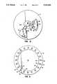
- FIG. 1is a perspective view of a Centrifugal rotor constructed in accordance with the principles of the present invention, with portions broken away.
- FIGS. 1A and 1Billustrate alternate geometries for a separation chamber of the type employed in a centrifugal rotor constructed in accordance with the principles of the present invention.
- FIG. 2is a top plan view of the centrifugal rotor of FIG. 1.
- FIG. 3is a vertical cross-sectional view of the rotor of FIGS. 1 and 2, taken along line 3--3 in FIG. 2.
- FIG. 4is a vertical cross-sectional view of the rotor of FIGS. 1 and 2, taken along line 4--4 in FIG. 2.
- FIG. 5is a horizontal cross-sectional view of the rotor of FIGS. 1-3, taken along line 5--5 in FIG. 3.
- FIG. 6is a horizontal cross-sectional view of the rotor of FIGS. 1-3, taken along line 6--6 in FIGS. 3 and 4.
- FIGS. 7-11illustrate the method of the present invention utilizing the centrifugal rotor of FIG. 1.
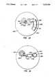
- FIG. 12illustrates an alternate embodiment of the centrifugal rotor of the present invention.
- FIG. 13is a top plan view of an exemplary embodiment of the analytical rotor with metering port, wherein the metering chamber entrance has a larger flow area than that of the overflow chamber entrance.
- the present inventionprovides apparatus and methods for separating cellular components from biological fluids, and in particular for separating whole blood into plasma which may then be subjected to a wide variety of analytic procedures.
- the apparatus and methodswill also provide for distribution of the separated plasma into a plurality of test wells within the rotor so that different analytic procedures may be performed without having to transfer aliquots of the plasma from the apparatus.
- the apparatus and methodare able to separate very low volumes of blood, usually as low as about 0.03 cc, frequently as low as about 0.015 cc, and sometimes as low as about 0.005 cc, although the present invention is suitable for separating much larger volumes as well.
- the present inventiondoes not require the use of a displacement medium for effecting the desired separation and distribution, and the apparatus design is very simple with no separate or moving parts required. Of course, it may be desirable in certain circumstances to provide such separate or moving parts, but they are not required in order to achieve the blood separation according to the method of the present invention.
- the apparatusis very easy to manufacture and can be produced at a very low cost, making the apparatus suitable for use as a disposable in testing whole-blood samples.
- the apparatus and methodare able to separate precise volumes of blood without the need to premeasure the amount applied to the apparatus.
- the apparatuscan further provide for automatic combination of the separated plasma with a reagent or diluent and can apportion substantially equal volumes of plasma among the plurality of test wells.
- the apparatusis suitable for use with a variety of conventional analytic measurement devices, such as spectrophotometers and fluorometers, which allow the plasma in the test wells to be individually examined without the need to remove the plasma from the wells.
- the present inventionis particularly suitable for separating cells from blood to produce plasma, it will be useful with a wide variety of other biological fluids, such as urine, sputum, semen, saliva, ocular lens fluid, cerebral fluid, spinal fluid, amniotic fluid, and tissue culture media, as well as food and industrial chemicals, and the like, where it may be desirable to separate cells and other interfering substances prior to analysis or assay.
- biological fluidssuch as urine, sputum, semen, saliva, ocular lens fluid, cerebral fluid, spinal fluid, amniotic fluid, and tissue culture media, as well as food and industrial chemicals, and the like, where it may be desirable to separate cells and other interfering substances prior to analysis or assay.
- centrifugal rotor of the present inventionmay be adapted to be used with most types of centrifuges which are now available or which may become available in the future.
- the centrifugal rotorcomprises a body structure which maintains a desired geometric pattern or relationship between a plurality of chambers and interconnecting passages, as described in more detail hereinbelow.
- the bodywill be a substantially solid plate with the chambers and passages formed as spaces or voids in an otherwise solid matrix.
- such solid plate structuresmay be formed by laminating a plurality of separately formed layers together into a composite structure where the chambers and passages are generally formed between adjacent layers.
- the individual layersmay be formed by injection molding, machining, and combinations thereof, and will usually be joined together, typically using a suitable adhesive or by ultrasonic welding. The final enclosed volumes are formed when the layers are brought together.
- the centrifugal rotormay be formed from a wide variety of materials and may optionally include two or more materials. Usually, the materials will be transparent so that the presence and distribution of blood, plasma, and other reagents, may be observed within the various internal chambers and passages. Also, it is generally required that the test wells formed within the rotor have suitable optical paths formed therethrough so that the contents of the test well may be observed spectrophotometrically, fluorometrically, or by other visual assessment instruments. In the exemplary embodiment described below, the rotor is formed from acrylic resins having the required optical properties, at least in those areas which define the optical paths.
- the apparatus and method of the present inventionare suitable for performing a wide variety of analytic procedures which are beneficially or necessarily performed on blood plasma.
- the analytic procedureswill generally require that the blood plasma be combined with one or more reagents so that some visibly detectable change occurs in the plasma which may be related to measurement of a particular component or characteristic of the plasma.
- the plasmawill undergo a reaction or other change which results in a change in color, fluorescence, luminescence, or the like, which may be measured by conventional spectrophotometers, fluorometers, light detectors, etc.
- immunoassays and other specific binding assaysmay be performed in the test wells.
- such assay proceduresmust be homogeneous and not require a separation step.
- it will be possible to accommodate heterogeneous assay systemsby providing a means to separate blood plasma from the test wells after an immunological reaction step has occurred.
- the rotor 10is in the form of a substantially solid disk including a top layer 12, middle layer 14, and bottom layer 16 laminated together to form a composite structure.
- each of the layers 12, 14, and 16will be composed of the same material, usually a transparent plastic such as an acrylate, but it is possible that the layers will be composed of different materials and that each layer may include two or more different materials forming different portions of the layer.
- the exposed surface of top layer 12will be referred to as the top surface while the exposed surface of the bottom layer 16 will be referred to as the bottom surface.
- a receptacle 18is formed in the bottom surface of layer 16 and is generally aligned with the vertical axis 20 of the rotor, as best observed in FIGS. 3 and 4.
- the receptacle 18is formed to mate with the drive shaft of a conventional centrifuge system, as described previously.
- the upper surface of middle layer 14includes a plurality of chambers and passages formed therein.
- the chambers and passagesmay be formed by machining a disk having generally flat surfaces or may be formed by injection molding of a suitable plastic resin in order to initially form the disk.
- the middle layer 14includes a metering chamber 40 having an inlet segment 42 which is generally aligned with the blood application port 22 in top layer 12.
- the metering chamber 40is connected to an overflow chamber 44 by a connecting passage 46, with the overflow chamber being located radially outward from the metering chamber.
- a vent connector passage 48extends from the radially-outward end of overflow chamber 44, first in a generally annular direction and thereafter in a generally radially-inward direction.
- the distal terminus 50 of passage 46is aligned with vent port 28 in top layer 12 so that the outward radial extremity of overflow chamber 44 will be vented to the atmosphere during use of the rotor 10.
- the depth of metering chamber 40 and overflow chamber 44will be selected to provide for capillary dimensions when the chambers are completed by lamination of the top layer 12. Typically, the depth will be in the range from about 0.1 to 1.0 mm, more typically being in the range from about 0.25 to 0.75 mm. Usually, the depth will be uniform for both chambers 40 and 44 as well as the connecting passage 46, although it will be possible to vary the depth so long as capillarity is maintained.
- a separation chamber 60is formed in the upper surface of middle layer 14 and is disposed radially outward from the metering chamber 40.
- the separation chamber 60includes a cell trap 62 formed at its radially-outward periphery and a receptacle region 65 formed along its radially-inward perimeter.
- a capillary region 66is formed between the receptacle region 65 and the cell trap 62 in order to inhibit the backflow of cells after they have entered the cell trap 62 as a result of centrifugal separation.
- the receptacle region 65provides a volume which is capable of receiving whole blood or other biological fluid (optionally combined with a diluent or reagent) and which retains the blood plasma or other separated fluid after centrifugation has been completed.
- the volume of overflow chamber 44will generally be larger than that of the metering chamber 40 in order to accommodate excess blood which may be applied through blood application port 42. Generally, the volume of the overflow chamber 44 will be at least twice that of the metering chamber 40, typically being three or more times larger.
- the volume of separation chamber 60will be selected to accommodate the expected volume of plasma and optionally reagent or diluent which can flow from the metering chamber 40 and reagent chamber 80 (as described below).
- the volume of the receptacle region 65will be in the range from about 0.1 cc to 1.0 cc. more typically being in the range from about 0.25 cc to 0.50 cc.
- the volume of the cell trap 62will depend at least in part on the volume of the receptacle region 65. In order to maximize the efficiency of separation, i.e., increase the amount of plasma obtained from a fixed amount of whole blood, it is desirable that the volume of the cell trap 62 be just large enough to accommodate the largest expected volume of cellular material.
- the volume of cell trap 62will then be the expected percentage of the volume of metering chamber 40.
- the volume of cell trap 62will be from about 100% to 200% of the volume of metering chamber 40.
- a reagent chamber 80is also formed in the upper surface of middle layer 14 and connected to the separation chamber 60 through a capillary passage 82.
- the reagent chamber 80will be disposed radially inward from the separation chamber 60 so that flow of reagent or diluent from the reagent chamber to the separation chamber 60 may be effected by spinning the rotor 14, as will be described in more detail hereinafter.
- the capillary passage 80terminates with an open channel in wall 72. In this way, flow of reagent from chamber 80 will not occur in the absence of outward centrifugal force resulting from spinning of the rotor 10.
- a removable seal or barrier in chamber 82or contain the reagent within a pouch or other package, to preserve the reagent and further assure that the reagent will not leak from chamber 80.
- a barrier, seal or packagewill be particularly desirable when the reagent is "prepackaged" into the centrifugal rotor 10 at a central preparation facility and later subjected to shipping, storing, and other handling procedures which might otherwise cause the reagent to degrade or leak.
- the reagent chamber 80may have substantially greater depth than the metering chamber 40 since the ability to provide capillary flow is not necessary. Thus, it is easy to store volumes of reagent which are substantially greater than the volume of blood or plasma which is provided to separation chamber 60 from metering chamber 40.
- the volume of the test wells 92will usually be relatively low, typically being in the range from about 0.005 cc to 0.015 cc, more usually being in the range from about 0.008 cc to 0.010 cc. It is possible that liquid, dried, or lyophilized reagents may be provided within the individual test wells so that combination occurs with the plasma when it is introduced. Alternatively, the walls or bottom of the test well 92 may be derivatized with various active components, such as antibodies, antigens, receptors, or the like, which are intended to take part in the analytic procedure.
- the central feature of the separation chamber 60is the capillary region 66, which is preferably an annular space having an inner arcuate boundary 200 and an outer arcuate boundary 202.
- the capillarity of region 66is broken at each boundary 200 and 202 as the size of the adjoining regions, i.e., receptacle region 65 and cell trap 62, are increased to break the capillarity.
- fluidwill be unable to flow through the capillary region 66 except when sufficient centrifugal force is applied by centrifugation.
- the shapes of the receptacle region 65 and cell trap 62may vary substantially.
- the receptacle region 65will generally be tapered so that the distance between opposed horizontal surfaces increases in the radially inward direction. Such increasing distance provides the desired capillarity break, as discussed above.
- the tapermay be provided by inclining the lower surface relative to the horizontal plane (FIG. 1), inclining the upper surface relative to the horizontal plane (FIG. 1A), or inclining both surfaces (FIG. 1B).
- the angle between the opposed surfaces of receptacle region 65is not critical, typically being between 0° and 40°, and usually being between 18° and 22°.
- the inner arcuate boundary 200 of the capillary regionis usually formed contiguously with the narrow end of the tapered receptacle region which defines an arcuate aperture.
- the cell trap 62is typically formed as an annular well which penetrates axially downward in the rotor and which is disposed contiguously with the outer arcuate boundary 202 of the annular space of the capillary region 66.
- the cell trap 62may also extend upwardly, as illustrated in FIG. 1B, need not have a true annular shape.
- downward flow of plasma or other separated fluid through axial port 64may be restricted by surface tension.
- the surface tensioncan be disrupted by abruptly stopping the spinning of the rotor 10 after separation has been achieved. Such cessation of spinning will cause the fluid to wet the wall of the region 65, allowing downflow.
- reagent chamber 80will be filled with reagent to a desired volume. As illustrated, the chamber 80 is entirely filled, but it is also possible that the chamber will be partially filled.
- the reagentmay be loaded into rotor 10 either at a central preparation facility or immediately prior to use by the user. In the later case, the reagent may be filled using a pipette through vent port 24.
- Whole bloodmay be loaded onto the rotor 10 through application port 24 in a volume greater than that which can be accommodated by measuring chamber 40.
- the bloodAs soon as the blood is applied through port 22, it will begin to flow laterally both into the main portion of chamber 40 and through passage 46 into overflow chamber 44 by capillary action. Since the flow area into measuring chamber 40 is substantially larger than that through passage 46, the measuring chamber will quickly fill with blood, with the overflow passing into overflow chamber 44. In this way, the blood applied through port 22 need not be carefully measured prior to application. After a time sufficient for the blood to partition between measuring chamber 40 and overflow chamber 44, the distribution of blood will be as illustrated in FIG. 7 with the capillary portion of chamber 40 being completely filled and overflow chamber 44 being partially filled.
- the rotor 10will be centrifuged or spun at a rate sufficient to cause the blood from chamber 40 and reagent from chamber 80 to flow into separation chamber 60. Additionally, the blood in overflow chamber 44 will flow radially outward, as illustrated.
- the rotor 10will be spun at a rate in the range from about 1500 rpm to 5000 rpm, more usually from about 2500 rpm to 4000 rpm, for a time in the range from about 20 seconds to 5 minutes, more typically being about 1 minute to 3 minutes, so that the cellular components of the blood will flow into trap 66 while the plasma will remain generally in the open portion of separation chamber 60.
- the rotor 100will generally be a laminate structure similar to rotor 10, with only a middle layer 102 being illustrated in FIG. 12.
- the upper layerwill include an application port (not illustrated) which is aligned with an entry chamber 104 formed in the upper surface of layer 102.
- the entry chamber 104is generally aligned with the vertical (spinning) axis of the rotor 100, and a pair of passages 106 and 108 extend radially outward from said entry port.
- Chamber 106serves as the measuring chamber and has a larger cross-sectional area than passage 108 so that it will fill more rapidly.
- Chamber 108serves as the overflow chamber so that it can take up any excess blood which is applied through entry chamber 104.
- a reagent chamber 110is located radially outward from the entry chamber 104 and connects with a non-capillary passage 112, which is connected with the distal end of chamber 106 and extends generally radially outward.
- a drainage port 126formed at the radially-inward periphery of separation chamber 114.
- the bottom floor of chamber 114will be sloped downward in the inward radial direction to promote the drainage of plasma through port 126.
- a collection chamberwill be formed beneath the drainage port 126 in a manner similar to that illustrated in FIGS. 1-6.
- a sample application port 204is situated in an interior portion of an analytical rotor body 202 and opens through a top surface 203 of the analytical rotor body, into which a fluid sample is introduced.
- a circular ridge 214extending vertically from the top surface 203 of the analytical rotor 202 and provides a convenient site for placement of a finger in a fingerstick application.
- the ridge 214highlights the location of the entry port to indicate the proper location for introduction of the fluid sample.
- a metering chamber 206is disposed within the rotor body 202 and is positioned radially outward from sample application port 204.
- the metering chamber 206has an inlet segment 216 connected to sample application port 204.
- the cross-sectional dimensions of the inlet segment 216 and the remainder of the metering chamber 206will be selected to provide capillary flow of the fluid from the application port 204 so that the chamber 206 can be filled while the rotor remains stationary.
- An overflow chamber 210is disposed within the rotor body 202 and is positioned radially outward from sample application port 204 and separated from metering chamber 206.
- Overflow chamber 210has a connecting passage 218.
- the cross-sectional dimensions of the connecting passage 218 and the remainder of the overflow chamber 218will also be selected to provide capillary flow of fluid from the application port 204 while the rotor remains stationary. Relative flow rates into the metering chamber 206 and the overflow chamber 210 will be controlled, however, so that filling of the metering chamber can be assured with the overflow chamber receiving only excess fluid. In this way, a precisely measured volume of fluid (determined by the volume of the metering chamber) can be provided for subsequent treatment and analysis as described generally above.
- the axial depths of metering chamber 206 and overflow chamber 210will be selected to provide for capillary dimensions when the chambers are completed by lamination of the top layer of the analytical rotor.
- the depthwill be in the range from about 0.1 mm to 1.0 mm, more typically being in the range from about 0.25 mm to 0.75 mm.
- the depthwill be uniform for both chambers 206 and 210 as well as inlet segment 216 and connecting passage 218, although it will be possible to vary the depth so long as capillarity is maintained.
- the volume of metering chamber 206will vary depending on the desired application, but will usually be selected to be as low as possible to provide a desired amount of fluid to the receiving chamber 208. Typically, the volume of metering chamber 206 will be in the range from about 0.005 cc to 0.05 cc, more typically being in the range from about 0.030 cc 0.040 cc.
- the relative flow rates of fluid into the metering chamber 206 and the overflow chamber 210may be controlled by adjusting the relative cross-sectional areas of the inlet segment 216 and the connecting passage 218. Conveniently, this can be done by providing an inlet segment 216 which is substantially wider than the connecting passage, as illustrated. In this way, the depths of the metering chamber 206 and the overflow chamber 210 may be maintained within the desired range of capillarity while flow rates can be varied substantially by adjusting the relative widths, with the width of the inlet passage 216 usually being at least twice the width of the connecting passage 218, more usually being at least three times, and frequently being at least four times the width.
- Whole bloodmay be loaded onto the analytical rotor body 202 through sample application port 204 in a volume greater than that which can be accommodated by metering chamber 206.
- the bloodwill begin to flow laterally both into the main portion of metering chamber 206 and into overflow chamber 210 by capillary action (both chambers are vented to permit inflow). Since the flow area into metering chamber 206 is substantially larger than that through overflow chamber 210, the metering chamber will quickly fill with blood, with the overflow passing into overflow chamber 210. Filling of the metering chamber 206 will stop when the fluid reaches the passage 220 which defines a capillary break. Fluid will continue to flow into the overflow chamber 210 until all fluid from the sample application port 204 has been drained. In this way the blood applied through sample application port 204 need not be carefully measured prior to application.
- metering chamber 206After a time sufficient for the blood or other fluid sample to partition between the measuring chamber 206 and overflow chamber 210, metering chamber 206 will be completely filled and overflow chamber 210 will be partially filled.
- the analytical rotor 202is then spun on a centrifuge to cause the blood in metering chamber 206 to move through passage 220 into receiving chamber 208.
- the bloodmay then be separated into component parts and subject to analytical tests, as described above in connection with the previous embodiments.
- a metering chamber 232 and overflow chamber 234are each provided with a vent 236 and 238, respectively.
- the vent 238 in the overflow chamber 234is constructed so as to be initially closed when the sample is introduced into sample application port 240. By maintaining vent 238 closed, initial flow of fluid from port 240 into the overflow chamber 234 is prevented. Vent 236, however, will be open so that metering chamber 232 can fill prior to any flow into the overflow chamber 234.
- the vent 238will be blocked in a manner that permits its opening (unblocking) by the user at a desired time, as described more fully below.
- the vent 238could be covered by a membrane, such as a plastic or metal foil, which can subsequently be pierced or pulled back by the user to open the vent.
- the vent 236 in the metering chamber 232will usually be constructed in a permanently open configuration, but could be covered (so long as the user removes the cover before the cover on vent 238 is removed).
- Whole bloodmay be loaded onto the analytical rotor 230 through the sample application port 240 in a volume greater than that which can be accommodated by metering chamber 232.
- the vent 238 in overflow chamber 210is kept closed when the blood is applied, while the vent 236 in metering chamber 232 (actually in receiving chamber 242, but connected to metering chamber 232 by connector port 244) remains open, permitting the blood in sample application port 240 to flow only into metering chamber 238.
- the vent 238 in overflow chamber 234is opened, permitting any excess blood in sample application port 240 to flow into the overflow chamber.
- the rotor 230may be spun on the centrifuge to cause the fluid in metering chamber 232 to flow through passage 244 into receiving chamber 242 for separation and analysis.
- an indicator window 250may be provided in metering chambers 206 and 232, respectively, to permit visual confirmation that the metering chamber has been filled with fluid.
- the indicator window 250will typically be a transparent window structure formed in the top surface of the rotor through which the quantity of fluid present in metering chamber 206 is visible.
- the operator or an instrumentcan detect when the metering chamber 206 or 232 is filled with fluid so that the rotor 202 in the first embodiment may be spun to move the fluid to receiving chamber 208, or, in the other embodiment, the vent 238 in overflow chamber 210 may be opened.
- an anticoagulant layer deposited on the interior surfaces of overflow chambers 210 and 234 and metering chambers 206 and 232helps to prevent clotting of blood before tests have been completed.
- An anti-coagulantsuch as lithium heparin is suitable for this purpose.
- a surfactant layermay be deposited on the interior surfaces of the chambers.
- a surfactantis chosen which does not lyse the blood cells, unless lysis is desired.
- the surfactantmay also be deposited at selected areas along the interior surfaces to create variable filling rates or zones of faster and slower filling rates.
- metering chambersmay be provided in order to run simultaneous tests and assays which require different test conditions.
- multiple metering chambersmay be provided to allow combination with different reagents or diluents in isolated separation chambers.
- a single metering chambermay be connected by separate capillary passages to control flow into separate separation chambers. In either case, assays and tests requiring different protocols can be carried in a single rotor system.
Landscapes
- Health & Medical Sciences (AREA)
- Chemical & Material Sciences (AREA)
- Life Sciences & Earth Sciences (AREA)
- Engineering & Computer Science (AREA)
- Analytical Chemistry (AREA)
- General Health & Medical Sciences (AREA)
- Hematology (AREA)
- Physics & Mathematics (AREA)
- Biomedical Technology (AREA)
- General Physics & Mathematics (AREA)
- Biochemistry (AREA)
- Chemical Kinetics & Catalysis (AREA)
- Pathology (AREA)
- Molecular Biology (AREA)
- Immunology (AREA)
- Clinical Laboratory Science (AREA)
- Urology & Nephrology (AREA)
- Medicinal Chemistry (AREA)
- Food Science & Technology (AREA)
- Ecology (AREA)
- Biophysics (AREA)
- Dispersion Chemistry (AREA)
- Investigating Or Analysing Biological Materials (AREA)
- Automatic Analysis And Handling Materials Therefor (AREA)
- Sampling And Sample Adjustment (AREA)
- Centrifugal Separators (AREA)
Abstract
Description
Claims (21)
Priority Applications (6)
| Application Number | Priority Date | Filing Date | Title |
|---|---|---|---|
| US07/783,041US5242606A (en) | 1990-06-04 | 1991-10-29 | Sample metering port for analytical rotor having overflow chamber |
| AU29255/92AAU2925592A (en) | 1991-10-29 | 1992-10-27 | Sample metering port for analytical rotor |
| JP50849293AJP3256542B2 (en) | 1991-10-29 | 1992-10-27 | Sample metering port of analysis rotor |
| CA002120244ACA2120244A1 (en) | 1991-10-29 | 1992-10-27 | Sample metering port for analytical rotor |
| EP19920923436EP0611323A4 (en) | 1991-10-29 | 1992-10-27 | Sample metering port for analytical rotor. |
| PCT/US1992/009084WO1993008893A1 (en) | 1991-10-29 | 1992-10-27 | Sample metering port for analytical rotor |
Applications Claiming Priority (2)
| Application Number | Priority Date | Filing Date | Title |
|---|---|---|---|
| US07/532,524US5061381A (en) | 1990-06-04 | 1990-06-04 | Apparatus and method for separating cells from biological fluids |
| US07/783,041US5242606A (en) | 1990-06-04 | 1991-10-29 | Sample metering port for analytical rotor having overflow chamber |
Related Parent Applications (1)
| Application Number | Title | Priority Date | Filing Date |
|---|---|---|---|
| US07/532,524Continuation-In-PartUS5061381A (en) | 1990-06-04 | 1990-06-04 | Apparatus and method for separating cells from biological fluids |
Publications (1)
| Publication Number | Publication Date |
|---|---|
| US5242606Atrue US5242606A (en) | 1993-09-07 |
Family
ID=25127997
Family Applications (1)
| Application Number | Title | Priority Date | Filing Date |
|---|---|---|---|
| US07/783,041Expired - LifetimeUS5242606A (en) | 1990-06-04 | 1991-10-29 | Sample metering port for analytical rotor having overflow chamber |
Country Status (6)
| Country | Link |
|---|---|
| US (1) | US5242606A (en) |
| EP (1) | EP0611323A4 (en) |
| JP (1) | JP3256542B2 (en) |
| AU (1) | AU2925592A (en) |
| CA (1) | CA2120244A1 (en) |
| WO (1) | WO1993008893A1 (en) |
Cited By (104)
| Publication number | Priority date | Publication date | Assignee | Title |
|---|---|---|---|---|
| US5409665A (en)* | 1993-09-01 | 1995-04-25 | Abaxis, Inc. | Simultaneous cuvette filling with means to isolate cuvettes |
| US5472603A (en)* | 1992-04-02 | 1995-12-05 | Abaxis, Inc. | Analytical rotor with dye mixing chamber |
| US5618494A (en)* | 1993-04-07 | 1997-04-08 | British Technology Group Limited | Capillary flow liquid transfer device having waste reception area |
| US5650334A (en)* | 1995-08-31 | 1997-07-22 | First Medical, Inc. | Fluorescent labelling compositions and methods for their use |
| US5916522A (en)* | 1997-08-07 | 1999-06-29 | Careside, Inc. | Electrochemical analytical cartridge |
| US5919711A (en)* | 1997-08-07 | 1999-07-06 | Careside, Inc. | Analytical cartridge |
| US5923431A (en)* | 1998-04-14 | 1999-07-13 | Uop Llc | Spectroscopic helical separator and fluid sample interface |
| US6002475A (en)* | 1998-01-28 | 1999-12-14 | Careside, Inc. | Spectrophotometric analytical cartridge |
| US6030581A (en)* | 1997-02-28 | 2000-02-29 | Burstein Laboratories | Laboratory in a disk |
| US6049388A (en)* | 1998-04-14 | 2000-04-11 | Uop Llc | Spectroscopic fluid sample cell |
| US6143248A (en)* | 1996-08-12 | 2000-11-07 | Gamera Bioscience Corp. | Capillary microvalve |
| US6143247A (en)* | 1996-12-20 | 2000-11-07 | Gamera Bioscience Inc. | Affinity binding-based system for detecting particulates in a fluid |
| US6162400A (en)* | 1998-08-12 | 2000-12-19 | Agilent Technologies, Inc. | Apparatus for controlling reactions |
| WO2001043796A2 (en) | 1999-12-16 | 2001-06-21 | Biosafe Laboratories, Inc. | Whole blood collection device and method |
| US6299839B1 (en) | 1995-08-31 | 2001-10-09 | First Medical, Inc. | System and methods for performing rotor assays |
| US6302134B1 (en) | 1997-05-23 | 2001-10-16 | Tecan Boston | Device and method for using centripetal acceleration to device fluid movement on a microfluidics system |
| US6348176B1 (en) | 1999-02-11 | 2002-02-19 | Careside, Inc. | Cartridge-based analytical instrument using centrifugal force/pressure for metering/transport of fluids |
| US6391264B2 (en) | 1999-02-11 | 2002-05-21 | Careside, Inc. | Cartridge-based analytical instrument with rotor balance and cartridge lock/eject system |
| US20020064480A1 (en)* | 1998-07-20 | 2002-05-30 | Shartle Robert Justice | Fluidic device for medical diagnostics |
| US20020076354A1 (en)* | 2000-12-01 | 2002-06-20 | Cohen David Samuel | Apparatus and methods for separating components of particulate suspension |
| US20020098528A1 (en)* | 2000-11-17 | 2002-07-25 | Gordon John F. | Methods and apparatus for blood typing with optical bio-disc |
| US20020097632A1 (en)* | 2000-05-15 | 2002-07-25 | Kellogg Gregory J. | Bidirectional flow centrifugal microfluidic devices |
| US20020098114A1 (en)* | 1998-07-20 | 2002-07-25 | Harding Ian A. | Microdroplet dispensing for a medical diagnostic device |
| US20020196435A1 (en)* | 2000-11-22 | 2002-12-26 | Cohen David Samuel | Apparatus and methods for separating agglutinants and disperse particles |
| US6511814B1 (en) | 1999-03-26 | 2003-01-28 | Idexx Laboratories, Inc. | Method and device for detecting analytes in fluids |
| US6531095B2 (en) | 1999-02-11 | 2003-03-11 | Careside, Inc. | Cartridge-based analytical instrument with optical detector |
| US6551842B1 (en) | 1999-03-26 | 2003-04-22 | Idexx Laboratories, Inc. | Method and device for detecting analytes in fluids |
| US20030104486A1 (en)* | 2000-11-16 | 2003-06-05 | Selvan Gowri Pyapali | Methods and apparatus for detecting and quantifying lymphocytes with optical biodiscs |
| US20030113925A1 (en)* | 2001-09-07 | 2003-06-19 | Gordon John Francis | Nuclear morphology based identification and quantification of white blood cell types using optical bio-disc systems |
| US20030129665A1 (en)* | 2001-08-30 | 2003-07-10 | Selvan Gowri Pyapali | Methods for qualitative and quantitative analysis of cells and related optical bio-disc systems |
| US20030143637A1 (en)* | 2001-08-31 | 2003-07-31 | Selvan Gowri Pyapali | Capture layer assemblies for cellular assays including related optical analysis discs and methods |
| US6602719B1 (en) | 1999-03-26 | 2003-08-05 | Idexx Laboratories, Inc. | Method and device for detecting analytes in fluids |
| US6632399B1 (en) | 1998-05-22 | 2003-10-14 | Tecan Trading Ag | Devices and methods for using centripetal acceleration to drive fluid movement in a microfluidics system for performing biological fluid assays |
| US20030219713A1 (en)* | 2001-11-20 | 2003-11-27 | Valencia Ramoncito Magpantay | Optical bio-discs and fluidic circuits for analysis of cells and methods relating thereto |
| US20030224457A1 (en)* | 2000-11-17 | 2003-12-04 | Hurt Susan Newcomb | Methods and apparatus for blood typing with optical bio-discs |
| US20030230383A1 (en)* | 2001-07-24 | 2003-12-18 | Glenn Sasaki | Method and apparatus for bonded fluidic circuit for optical bio-disc |
| US20030232403A1 (en)* | 1999-06-18 | 2003-12-18 | Kellogg Gregory L. | Devices and methods for the performance of miniaturized homogeneous assays |
| US20040018116A1 (en)* | 2002-07-26 | 2004-01-29 | Desmond Sean M. | Microfluidic size-exclusion devices, systems, and methods |
| US20040038647A1 (en)* | 1993-12-20 | 2004-02-26 | Intermec Technologies Corporation | Local area network having multiple channel wireless access |
| US6709869B2 (en)* | 1995-12-18 | 2004-03-23 | Tecan Trading Ag | Devices and methods for using centripetal acceleration to drive fluid movement in a microfluidics system |
| US20040078145A1 (en)* | 2002-10-18 | 2004-04-22 | Ostoich Vladimir E. | Systems and methods for the detection of short and long samples |
| EP1419818A1 (en)* | 2002-11-14 | 2004-05-19 | Steag MicroParts GmbH | Device for sequential transport of liquids by capillary forces |
| US20040241381A1 (en)* | 2002-01-31 | 2004-12-02 | Chen Yihfar | Microfluidic structures with circumferential grooves for bonding adhesives and related optical analysis discs |
| US20050023765A1 (en)* | 2002-01-31 | 2005-02-03 | Coombs James Howard | Bio-safety features for optical analysis disc and disc system including same |
| US20050037484A1 (en)* | 2003-04-23 | 2005-02-17 | Norbert Staimer | Optical bio-discs including spiral fluidic circuits for performing assays |
| US20050047968A1 (en)* | 2003-06-19 | 2005-03-03 | Horacio Kido | Fluidic circuits for sample preparation including bio-discs and methods relating thereto |
| US20050084422A1 (en)* | 2003-06-19 | 2005-04-21 | Horacio Kido | Fluidic circuits for sample preparation including bio-discs and methods relating thereto |
| US20050153433A1 (en)* | 2001-08-28 | 2005-07-14 | Gyros Ab | Retaining microfluidic microcavity and other microfluidic structures |
| US20050176059A1 (en)* | 2002-01-31 | 2005-08-11 | Pal Andrew A. | Bio-safe dispenser and optical analysis disc assembly |
| US20050221048A1 (en)* | 2002-01-31 | 2005-10-06 | James Rodney Norton | Manufacturing processes for making optical analysis discs including successive patterning operations and optical discs thereby manufactured |
| EP1577010A3 (en)* | 1995-12-05 | 2005-11-16 | Tecan Trading AG | Microsystem platform and its use |
| US20060002817A1 (en)* | 2004-06-30 | 2006-01-05 | Sebastian Bohm | Flow modulation devices |
| US20060004303A1 (en)* | 2004-06-30 | 2006-01-05 | Weidenhaupt Klaus P | Fluid handling devices |
| US20060001551A1 (en)* | 2004-06-30 | 2006-01-05 | Ulrich Kraft | Analyte monitoring system with wireless alarm |
| US20060000709A1 (en)* | 2004-06-30 | 2006-01-05 | Sebastian Bohm | Methods for modulation of flow in a flow pathway |
| WO2006110095A1 (en) | 2005-04-14 | 2006-10-19 | Gyros Patent Ab | A microfluidic device with finger valves |
| US20060263265A1 (en)* | 2005-05-23 | 2006-11-23 | Der-Ren Kang | Blood micro-separator |
| US20060281192A1 (en)* | 2005-06-13 | 2006-12-14 | Harding Philip H | Method for mixing fluids in microfluidic systems |
| US20060280653A1 (en)* | 2005-06-13 | 2006-12-14 | Harding Philip H | Microfluidic centrifugation systems |
| US20060288762A1 (en)* | 2005-06-28 | 2006-12-28 | Phillip Harding | Microfluidic test systems with gas bubble reduction |
| US7169353B1 (en)* | 1999-03-09 | 2007-01-30 | Biomerieux S.A. | Apparatus enabling liquid transfer by capillary action therein |
| US20070166721A1 (en)* | 2003-06-27 | 2007-07-19 | Phan Brigitte C | Fluidic circuits, methods and apparatus for use of whole blood samples in colorimetric assays |
| US20070274863A1 (en)* | 2003-07-25 | 2007-11-29 | Horacio Kido | Fluidic circuits for sample preparation including bio-discs and methods relating thereto |
| WO2008037469A1 (en)* | 2006-09-27 | 2008-04-03 | Roche Diagnostics Gmbh | Rotatable test element |
| US20080110500A1 (en)* | 2005-03-09 | 2008-05-15 | The Regents Of The University Of California | Microfluidic Valve Liquids |
| US20080237151A1 (en)* | 2007-04-02 | 2008-10-02 | Samsung Electronics Co., Ltd. | Centrifugal force-based microfluidic device and microfluidic system including the same |
| US20080280365A1 (en)* | 2005-10-07 | 2008-11-13 | Albert-Ludwigs-Universiitat Freiburg | Apparatus and Method for Determining the Volume Fractions of the Phases in a Suspension |
| US20090122307A1 (en)* | 2007-10-26 | 2009-05-14 | Xin-Sheng Chai | Sensor technique for black liquor oxidation control |
| EP2075567A3 (en)* | 2005-07-08 | 2009-08-19 | Hemocue AB | A cuvette and a method and shaping tool for manufacture thereof |
| US20100255589A1 (en)* | 2007-10-30 | 2010-10-07 | Panasonic Corporation | Analyzing device, analyzing apparatus using the device, and analyzing method |
| EP1483052B1 (en)* | 2001-08-28 | 2010-12-22 | Gyros Patent Ab | Retaining microfluidic microcavity and other microfluidic structures |
| US20110053202A1 (en)* | 2009-08-25 | 2011-03-03 | Industrial Technology Research Institute | Analytical system, analytical method and flow-path structure |
| US20110195502A1 (en)* | 2010-02-05 | 2011-08-11 | Medi Medical Engineering Corp. | Centrifugal rotor and method for using the same for delivering biological sample |
| WO2011120819A1 (en)* | 2010-03-31 | 2011-10-06 | Roche Diagnostics Gmbh | Microfluidic element with multifunctional measurement chamber |
| US20140073041A1 (en)* | 2012-07-24 | 2014-03-13 | Panasonic Corporation | Analyzing device |
| US20140227149A1 (en)* | 2009-07-07 | 2014-08-14 | Sony Corporation | Microfluidic device adapted for post-centrifugation use with selective sample extraction and methods for its use |
| US20140296050A1 (en)* | 2011-10-10 | 2014-10-02 | Protectlife International Biomedical Inc. | Centrifugal rotor |
| US8961764B2 (en) | 2010-10-15 | 2015-02-24 | Lockheed Martin Corporation | Micro fluidic optic design |
| US9067207B2 (en) | 2009-06-04 | 2015-06-30 | University Of Virginia Patent Foundation | Optical approach for microfluidic DNA electrophoresis detection |
| US9322054B2 (en) | 2012-02-22 | 2016-04-26 | Lockheed Martin Corporation | Microfluidic cartridge |
| US10029035B2 (en) | 2015-03-04 | 2018-07-24 | Pensara, Inc | System, method and kit for the collection and processing of amniotic fluid and placental aspirate |
| US10197480B2 (en) | 2012-11-07 | 2019-02-05 | Sandstone Diagnostics, Inc. | Methods and devices for processing samples and counting cells |
| US10376877B2 (en) | 2013-02-07 | 2019-08-13 | Sandstone Diagnostics, Inc. | Automated sample processing, fluid distribution, and sedimentation assay |
| US10533994B2 (en) | 2006-03-24 | 2020-01-14 | Theranos Ip Company, Llc | Systems and methods of sample processing and fluid control in a fluidic system |
| US10557786B2 (en) | 2011-01-21 | 2020-02-11 | Theranos Ip Company, Llc | Systems and methods for sample use maximization |
| US10634667B2 (en) | 2007-10-02 | 2020-04-28 | Theranos Ip Company, Llc | Modular point-of-care devices, systems, and uses thereof |
| US10761030B2 (en) | 2005-05-09 | 2020-09-01 | Labrador Diagnostics Llc | System and methods for analyte detection |
| US10827965B2 (en) | 2013-04-15 | 2020-11-10 | Becton, Dickinson And Company | Biological fluid collection device and biological fluid separation and testing system |
| US10919039B2 (en) | 2016-06-27 | 2021-02-16 | Abaxis, Inc. | Devices with modified conduits |
| CN112601612A (en)* | 2018-08-24 | 2021-04-02 | 硕腾服务有限责任公司 | System and method for inspecting microfluidic rotor devices |
| CN112638531A (en)* | 2018-08-24 | 2021-04-09 | 硕腾服务有限责任公司 | Microfluidic rotor apparatus |
| CN112903744A (en)* | 2019-12-04 | 2021-06-04 | 爱尔伯股份公司 | Test strip support |
| US11139084B2 (en) | 2009-10-19 | 2021-10-05 | Labrador Diagnostics Llc | Integrated health data capture and analysis system |
| US11162947B2 (en) | 2006-05-10 | 2021-11-02 | Labrador Diagnostics Llc | Real-time detection of influenza virus |
| US11215610B2 (en) | 2006-10-13 | 2022-01-04 | Labrador Diagnostics Llc | Reducing optical interference in a fluidic device |
| CN114100710A (en)* | 2021-11-17 | 2022-03-01 | 江苏液滴逻辑生物技术有限公司 | System device, method and application for quantitatively injecting chip detection sample |
| US11287421B2 (en) | 2006-03-24 | 2022-03-29 | Labrador Diagnostics Llc | Systems and methods of sample processing and fluid control in a fluidic system |
| US11370177B2 (en) | 2018-08-24 | 2022-06-28 | Zoetis Services Llc | Systems and methods for manufacturing a microfluidic rotor device |
| US11628452B2 (en) | 2018-08-24 | 2023-04-18 | Zoetis Services Llc | Microfluidic rotor device |
| US11714034B2 (en) | 2012-11-07 | 2023-08-01 | Laboratory Corporation Of America Holdings | Methods and devices for processing samples and counting cells |
| US11754554B2 (en) | 2007-08-06 | 2023-09-12 | Labrador Diagnostics Llc | Systems and methods of fluidic sample processing |
| US12066450B2 (en) | 2018-06-20 | 2024-08-20 | Phc Holdings Corporation | Substrate for sample analysis |
| USD1067792S1 (en)* | 2020-07-02 | 2025-03-25 | Phc Holdings Corporation | Panel for biochemical analysis |
| US12290810B2 (en) | 2018-08-24 | 2025-05-06 | Zoetis Services Llc | Microfluidic rotor device |
Families Citing this family (22)
| Publication number | Priority date | Publication date | Assignee | Title |
|---|---|---|---|---|
| JP3847053B2 (en)* | 2000-03-15 | 2006-11-15 | 純 菊地 | Blood analyzer |
| JP4464158B2 (en) | 2004-02-13 | 2010-05-19 | キヤノン株式会社 | Biochemical reaction cartridge |
| WO2006077695A1 (en) | 2005-01-24 | 2006-07-27 | Matsushita Electric Industrial Co., Ltd. | Liquid delivery device and liquid delivery method |
| US8667833B2 (en) | 2007-10-29 | 2014-03-11 | Panasonic Corporation | Analysis device, and analysis apparatus and method using the same |
| JP5670197B2 (en)* | 2007-12-07 | 2015-02-18 | ミルテンイ バイオテック ゲーエムベーハー | Sample processing system and method |
| CN101809448B (en) | 2007-12-10 | 2013-05-15 | 松下电器产业株式会社 | Analyzer |
| JP5174627B2 (en) | 2008-01-21 | 2013-04-03 | パナソニック株式会社 | Analysis equipment |
| KR20120091631A (en)* | 2011-02-09 | 2012-08-20 | 삼성전자주식회사 | Microfluidic device |
| JP6548646B2 (en) | 2014-06-30 | 2019-07-24 | Phcホールディングス株式会社 | Rotation angle detection circuit, rotation angle detection method, sample analyzer and computer program for sample analyzer |
| JP6588908B2 (en) | 2014-06-30 | 2019-10-09 | Phcホールディングス株式会社 | Sample analysis substrate, sample analysis apparatus, sample analysis system, and program for sample analysis system |
| US10539560B2 (en) | 2014-06-30 | 2020-01-21 | Phc Holdings Corporation | Substrate for sample analysis, and sample analysis apparatus |
| US10520521B2 (en) | 2014-06-30 | 2019-12-31 | Phc Holdings Corporation | Substrate for sample analysis, sample analysis device, sample analysis system, and program for sample analysis system |
| WO2016002728A1 (en) | 2014-06-30 | 2016-01-07 | パナソニックヘルスケアホールディングス株式会社 | Substrate for sample analysis, sample analysis device, sample analysis system, and method for removing liquid from liquid that contains magnetic particles |
| KR101776245B1 (en)* | 2014-11-20 | 2017-09-11 | 울산과학기술원 | Particle filtration device and method of particle filtration |
| US10539583B2 (en) | 2014-12-12 | 2020-01-21 | Phc Holdings Corporation | Substrate for sample analysis, sample analysis device, sample analysis system, and program for sample analysis system |
| EP3173149A1 (en)* | 2015-11-26 | 2017-05-31 | Roche Diagnostics GmbH | Determining a quantity of an analyte in a blood sample |
| WO2017111128A1 (en) | 2015-12-24 | 2017-06-29 | パナソニックヘルスケアホールディングス株式会社 | Sample analysis substrate, sample analysis device, sample analysis system, and program for sample analysis |
| US11262356B2 (en) | 2015-12-28 | 2022-03-01 | Phc Holdings Corporation | Specimen analysis substrate, specimen analysis device, specimen analysis system, and program for specimen analysis system |
| WO2018134387A1 (en)* | 2017-01-20 | 2018-07-26 | Université Libre de Bruxelles | Immunoassay methods and devices |
| US10293340B2 (en) | 2017-10-11 | 2019-05-21 | Fitbit, Inc. | Microfluidic metering and delivery system |
| EP3629008B1 (en) | 2018-09-26 | 2024-08-07 | PHC Holdings Corporation | Sample analysis system, and method of measuring luminescence of a sample |
| US11313858B2 (en) | 2018-09-26 | 2022-04-26 | Phc Holdings Corporation | Sample analysis device, sample analysis system, and method of measuring luminescence of a sample |
Citations (19)
| Publication number | Priority date | Publication date | Assignee | Title |
|---|---|---|---|---|
| US3864089A (en)* | 1973-12-10 | 1975-02-04 | Atomic Energy Commission | Multiple-sample rotor assembly for blood fraction preparation |
| US3873217A (en)* | 1973-07-24 | 1975-03-25 | Atomic Energy Commission | Simplified rotor for fast analyzer of rotary cuvette type |
| US3899296A (en)* | 1974-07-17 | 1975-08-12 | Us Energy | Whole blood analysis rotor for a multistation dynamic photometer |
| US3901658A (en)* | 1974-07-30 | 1975-08-26 | Us Energy | Whole blood analysis rotor assembly having removable cellular sedimentation bowl |
| US4035156A (en)* | 1977-01-21 | 1977-07-12 | The United States Of America As Represented By The United States Energy Research And Development Administration | Filter type rotor for multistation photometer |
| US4225558A (en)* | 1978-09-19 | 1980-09-30 | Honeywell Inc. | Fluid sample test apparatus and fluid sample cell for use therein |
| US4279862A (en)* | 1977-11-17 | 1981-07-21 | Bretaudiere Jean Pierre | Centrifugal photometric analyzer |
| US4284602A (en)* | 1979-12-10 | 1981-08-18 | Immutron, Inc. | Integrated fluid manipulator |
| US4689203A (en)* | 1984-01-11 | 1987-08-25 | Fluilogic Systems Oy | Centrifuge |
| US4740472A (en)* | 1985-08-05 | 1988-04-26 | The United States Of America As Represented By The United States Department Of Energy | Method and apparatus for automated processing and aliquoting of whole blood samples for analysis in a centrifugal fast analyzer |
| US4847205A (en)* | 1987-04-08 | 1989-07-11 | Martin Marietta Energy Systems, Inc. | Device and method for automated separation of a sample of whole blood into aliquots |
| US4868129A (en)* | 1987-08-27 | 1989-09-19 | Biotrack Inc. | Apparatus and method for dilution and mixing of liquid samples |
| US4876203A (en)* | 1984-10-26 | 1989-10-24 | Jean Guigan | Method of performing medical analysis on a liquid sample using at least one dry reagent, and apparatus for the method |
| US4963498A (en)* | 1985-08-05 | 1990-10-16 | Biotrack | Capillary flow device |
| US5061381A (en)* | 1990-06-04 | 1991-10-29 | Abaxis, Inc. | Apparatus and method for separating cells from biological fluids |
| US5104813A (en)* | 1989-04-13 | 1992-04-14 | Biotrack, Inc. | Dilution and mixing cartridge |
| US5160702A (en)* | 1989-01-17 | 1992-11-03 | Molecular Devices Corporation | Analyzer with improved rotor structure |
| US5173193A (en)* | 1991-04-01 | 1992-12-22 | Schembri Carol T | Centrifugal rotor having flow partition |
| US5186844A (en)* | 1991-04-01 | 1993-02-16 | Abaxis, Inc. | Apparatus and method for continuous centrifugal blood cell separation |
Family Cites Families (2)
| Publication number | Priority date | Publication date | Assignee | Title |
|---|---|---|---|---|
| US5122284A (en)* | 1990-06-04 | 1992-06-16 | Abaxis, Inc. | Apparatus and method for optically analyzing biological fluids |
| JP5536937B1 (en) | 2013-06-10 | 2014-07-02 | 株式会社 資生堂 | Mist cosmetics |
- 1991
- 1991-10-29USUS07/783,041patent/US5242606A/ennot_activeExpired - Lifetime
- 1992
- 1992-10-27WOPCT/US1992/009084patent/WO1993008893A1/ennot_activeApplication Discontinuation
- 1992-10-27CACA002120244Apatent/CA2120244A1/ennot_activeAbandoned
- 1992-10-27EPEP19920923436patent/EP0611323A4/ennot_activeWithdrawn
- 1992-10-27JPJP50849293Apatent/JP3256542B2/ennot_activeExpired - Lifetime
- 1992-10-27AUAU29255/92Apatent/AU2925592A/ennot_activeAbandoned
Patent Citations (19)
| Publication number | Priority date | Publication date | Assignee | Title |
|---|---|---|---|---|
| US3873217A (en)* | 1973-07-24 | 1975-03-25 | Atomic Energy Commission | Simplified rotor for fast analyzer of rotary cuvette type |
| US3864089A (en)* | 1973-12-10 | 1975-02-04 | Atomic Energy Commission | Multiple-sample rotor assembly for blood fraction preparation |
| US3899296A (en)* | 1974-07-17 | 1975-08-12 | Us Energy | Whole blood analysis rotor for a multistation dynamic photometer |
| US3901658A (en)* | 1974-07-30 | 1975-08-26 | Us Energy | Whole blood analysis rotor assembly having removable cellular sedimentation bowl |
| US4035156A (en)* | 1977-01-21 | 1977-07-12 | The United States Of America As Represented By The United States Energy Research And Development Administration | Filter type rotor for multistation photometer |
| US4279862A (en)* | 1977-11-17 | 1981-07-21 | Bretaudiere Jean Pierre | Centrifugal photometric analyzer |
| US4225558A (en)* | 1978-09-19 | 1980-09-30 | Honeywell Inc. | Fluid sample test apparatus and fluid sample cell for use therein |
| US4284602A (en)* | 1979-12-10 | 1981-08-18 | Immutron, Inc. | Integrated fluid manipulator |
| US4689203A (en)* | 1984-01-11 | 1987-08-25 | Fluilogic Systems Oy | Centrifuge |
| US4876203A (en)* | 1984-10-26 | 1989-10-24 | Jean Guigan | Method of performing medical analysis on a liquid sample using at least one dry reagent, and apparatus for the method |
| US4740472A (en)* | 1985-08-05 | 1988-04-26 | The United States Of America As Represented By The United States Department Of Energy | Method and apparatus for automated processing and aliquoting of whole blood samples for analysis in a centrifugal fast analyzer |
| US4963498A (en)* | 1985-08-05 | 1990-10-16 | Biotrack | Capillary flow device |
| US4847205A (en)* | 1987-04-08 | 1989-07-11 | Martin Marietta Energy Systems, Inc. | Device and method for automated separation of a sample of whole blood into aliquots |
| US4868129A (en)* | 1987-08-27 | 1989-09-19 | Biotrack Inc. | Apparatus and method for dilution and mixing of liquid samples |
| US5160702A (en)* | 1989-01-17 | 1992-11-03 | Molecular Devices Corporation | Analyzer with improved rotor structure |
| US5104813A (en)* | 1989-04-13 | 1992-04-14 | Biotrack, Inc. | Dilution and mixing cartridge |
| US5061381A (en)* | 1990-06-04 | 1991-10-29 | Abaxis, Inc. | Apparatus and method for separating cells from biological fluids |
| US5173193A (en)* | 1991-04-01 | 1992-12-22 | Schembri Carol T | Centrifugal rotor having flow partition |
| US5186844A (en)* | 1991-04-01 | 1993-02-16 | Abaxis, Inc. | Apparatus and method for continuous centrifugal blood cell separation |
Cited By (200)
| Publication number | Priority date | Publication date | Assignee | Title |
|---|---|---|---|---|
| US5472603A (en)* | 1992-04-02 | 1995-12-05 | Abaxis, Inc. | Analytical rotor with dye mixing chamber |
| US5693233A (en)* | 1992-04-02 | 1997-12-02 | Abaxis | Methods of transporting fluids within an analytical rotor |
| US5618494A (en)* | 1993-04-07 | 1997-04-08 | British Technology Group Limited | Capillary flow liquid transfer device having waste reception area |
| US5518930A (en)* | 1993-09-01 | 1996-05-21 | Abaxis, Inc. | Simultaneous cuvette filling with means to isolate cuvettes |
| US5409665A (en)* | 1993-09-01 | 1995-04-25 | Abaxis, Inc. | Simultaneous cuvette filling with means to isolate cuvettes |
| US20040038647A1 (en)* | 1993-12-20 | 2004-02-26 | Intermec Technologies Corporation | Local area network having multiple channel wireless access |
| US6319468B1 (en) | 1995-06-27 | 2001-11-20 | Tecan Trading Ag | Affinity binding-based system for detecting particulates in a fluid |
| US6299839B1 (en) | 1995-08-31 | 2001-10-09 | First Medical, Inc. | System and methods for performing rotor assays |
| US5650334A (en)* | 1995-08-31 | 1997-07-22 | First Medical, Inc. | Fluorescent labelling compositions and methods for their use |
| EP1577010A3 (en)* | 1995-12-05 | 2005-11-16 | Tecan Trading AG | Microsystem platform and its use |
| US6709869B2 (en)* | 1995-12-18 | 2004-03-23 | Tecan Trading Ag | Devices and methods for using centripetal acceleration to drive fluid movement in a microfluidics system |
| US6143248A (en)* | 1996-08-12 | 2000-11-07 | Gamera Bioscience Corp. | Capillary microvalve |
| US6143247A (en)* | 1996-12-20 | 2000-11-07 | Gamera Bioscience Inc. | Affinity binding-based system for detecting particulates in a fluid |
| US6656430B2 (en)* | 1996-12-20 | 2003-12-02 | Tecan Trading Ag | Affinity binding-based system for detecting particulates in a fluid |
| US20010048895A1 (en)* | 1997-02-28 | 2001-12-06 | Jorma Virtanen | Laboratory in a disk |
| LT4681B (en) | 1997-02-28 | 2000-07-25 | Burstein Laboratories, Inc | Laboratory in a disk |
| US6030581A (en)* | 1997-02-28 | 2000-02-29 | Burstein Laboratories | Laboratory in a disk |
| US6548788B2 (en) | 1997-05-23 | 2003-04-15 | Tecan Trading Ag | Devices and methods for using centripetal acceleration to drive fluid movement in a microfluidics system |
| US20040089616A1 (en)* | 1997-05-23 | 2004-05-13 | Gregory Kellogg | Devices and methods for using centripetal acceleration to drive fluid movement in a microfluidics system for performing biological fluid assays |
| US6399361B2 (en) | 1997-05-23 | 2002-06-04 | Tecan Trading Ag | Devices and methods for using centripetal acceleration to drive fluid movement in a microfluidics system |
| US6302134B1 (en) | 1997-05-23 | 2001-10-16 | Tecan Boston | Device and method for using centripetal acceleration to device fluid movement on a microfluidics system |
| US5919711A (en)* | 1997-08-07 | 1999-07-06 | Careside, Inc. | Analytical cartridge |
| US5916522A (en)* | 1997-08-07 | 1999-06-29 | Careside, Inc. | Electrochemical analytical cartridge |
| US6033914A (en)* | 1997-08-07 | 2000-03-07 | Careside, Inc. | Electrochemical analytical cartridge |
| US6002475A (en)* | 1998-01-28 | 1999-12-14 | Careside, Inc. | Spectrophotometric analytical cartridge |
| US6049388A (en)* | 1998-04-14 | 2000-04-11 | Uop Llc | Spectroscopic fluid sample cell |
| US5923431A (en)* | 1998-04-14 | 1999-07-13 | Uop Llc | Spectroscopic helical separator and fluid sample interface |
| US6632399B1 (en) | 1998-05-22 | 2003-10-14 | Tecan Trading Ag | Devices and methods for using centripetal acceleration to drive fluid movement in a microfluidics system for performing biological fluid assays |
| US20020098114A1 (en)* | 1998-07-20 | 2002-07-25 | Harding Ian A. | Microdroplet dispensing for a medical diagnostic device |
| US20030156983A1 (en)* | 1998-07-20 | 2003-08-21 | Shartle Robert Justice | Fluidic device for medical diagnostics |
| US20030210287A1 (en)* | 1998-07-20 | 2003-11-13 | Harding Ian A. | Microdroplet dispensing methods for a medical diagnostic device |
| US20020110486A1 (en)* | 1998-07-20 | 2002-08-15 | Shartle Robert Justice | Analyte test strip with two controls |
| US20020110922A1 (en)* | 1998-07-20 | 2002-08-15 | Shartle Robert Justice | Vacuum loaded test strip and method of use |
| US20030156984A1 (en)* | 1998-07-20 | 2003-08-21 | John Lemke | Fluidic device for medical diagnostics |
| US7022286B2 (en) | 1998-07-20 | 2006-04-04 | Lifescan, Inc. | Fluidic device for medical diagnostics |
| US20020064480A1 (en)* | 1998-07-20 | 2002-05-30 | Shartle Robert Justice | Fluidic device for medical diagnostics |
| US6521182B1 (en) | 1998-07-20 | 2003-02-18 | Lifescan, Inc. | Fluidic device for medical diagnostics |
| US20040109790A1 (en)* | 1998-07-20 | 2004-06-10 | Shartle Robert Justice | Vacuum loaded test strip with stop junction and bypass channel |
| US20020132355A1 (en)* | 1998-08-12 | 2002-09-19 | Schembri Carol T. | Method and apparatus for controlling reactions |
| US7247486B2 (en) | 1998-08-12 | 2007-07-24 | Agilent Technologies, Inc. | Method and apparatus for controlling reactions |
| US20070134799A1 (en)* | 1998-08-12 | 2007-06-14 | Schembri Carol T | Method and apparatus for controlling reactions |
| US6395553B1 (en)* | 1998-08-12 | 2002-05-28 | Agilent Technologies, Inc. | Method for controlling reactions |
| US6162400A (en)* | 1998-08-12 | 2000-12-19 | Agilent Technologies, Inc. | Apparatus for controlling reactions |
| US6531095B2 (en) | 1999-02-11 | 2003-03-11 | Careside, Inc. | Cartridge-based analytical instrument with optical detector |
| US6391264B2 (en) | 1999-02-11 | 2002-05-21 | Careside, Inc. | Cartridge-based analytical instrument with rotor balance and cartridge lock/eject system |
| US6348176B1 (en) | 1999-02-11 | 2002-02-19 | Careside, Inc. | Cartridge-based analytical instrument using centrifugal force/pressure for metering/transport of fluids |
| US7169353B1 (en)* | 1999-03-09 | 2007-01-30 | Biomerieux S.A. | Apparatus enabling liquid transfer by capillary action therein |
| US6602719B1 (en) | 1999-03-26 | 2003-08-05 | Idexx Laboratories, Inc. | Method and device for detecting analytes in fluids |
| US6511814B1 (en) | 1999-03-26 | 2003-01-28 | Idexx Laboratories, Inc. | Method and device for detecting analytes in fluids |
| US6551842B1 (en) | 1999-03-26 | 2003-04-22 | Idexx Laboratories, Inc. | Method and device for detecting analytes in fluids |
| US20030232403A1 (en)* | 1999-06-18 | 2003-12-18 | Kellogg Gregory L. | Devices and methods for the performance of miniaturized homogeneous assays |
| EP1242798A4 (en)* | 1999-12-16 | 2005-01-19 | Biosafe Lab Inc | Whole blood collection device and method |
| WO2001043796A2 (en) | 1999-12-16 | 2001-06-21 | Biosafe Laboratories, Inc. | Whole blood collection device and method |
| US20020097632A1 (en)* | 2000-05-15 | 2002-07-25 | Kellogg Gregory J. | Bidirectional flow centrifugal microfluidic devices |
| US6527432B2 (en)* | 2000-05-15 | 2003-03-04 | Tecan Trading Ag | Bidirectional flow centrifugal microfluidic devices |
| US20030104486A1 (en)* | 2000-11-16 | 2003-06-05 | Selvan Gowri Pyapali | Methods and apparatus for detecting and quantifying lymphocytes with optical biodiscs |
| US20020098528A1 (en)* | 2000-11-17 | 2002-07-25 | Gordon John F. | Methods and apparatus for blood typing with optical bio-disc |
| US20030224457A1 (en)* | 2000-11-17 | 2003-12-04 | Hurt Susan Newcomb | Methods and apparatus for blood typing with optical bio-discs |
| US7087203B2 (en) | 2000-11-17 | 2006-08-08 | Nagaoka & Co., Ltd. | Methods and apparatus for blood typing with optical bio-disc |
| US7026131B2 (en) | 2000-11-17 | 2006-04-11 | Nagaoka & Co., Ltd. | Methods and apparatus for blood typing with optical bio-discs |
| US20020196435A1 (en)* | 2000-11-22 | 2002-12-26 | Cohen David Samuel | Apparatus and methods for separating agglutinants and disperse particles |
| WO2002043866A3 (en)* | 2000-12-01 | 2003-03-06 | Burstein Technologies Inc | Apparatus and methods for separating components of particulate suspension |
| US20020076354A1 (en)* | 2000-12-01 | 2002-06-20 | Cohen David Samuel | Apparatus and methods for separating components of particulate suspension |
| US20030230383A1 (en)* | 2001-07-24 | 2003-12-18 | Glenn Sasaki | Method and apparatus for bonded fluidic circuit for optical bio-disc |
| US20050153433A1 (en)* | 2001-08-28 | 2005-07-14 | Gyros Ab | Retaining microfluidic microcavity and other microfluidic structures |
| US7300199B2 (en)* | 2001-08-28 | 2007-11-27 | Gyros Ab | Retaining microfluidic microcavity and other microfluidic structures |
| EP1483052B1 (en)* | 2001-08-28 | 2010-12-22 | Gyros Patent Ab | Retaining microfluidic microcavity and other microfluidic structures |
| US8268262B2 (en) | 2001-08-28 | 2012-09-18 | Gyros Patent Ab | Retaining microfluidic microcavity and other microfluidic structures |
| US20050153434A1 (en)* | 2001-08-28 | 2005-07-14 | Gyros Ab | Retaining microfluidic microcavity and other microfluidic structures |
| US20030129665A1 (en)* | 2001-08-30 | 2003-07-10 | Selvan Gowri Pyapali | Methods for qualitative and quantitative analysis of cells and related optical bio-disc systems |
| US20030143637A1 (en)* | 2001-08-31 | 2003-07-31 | Selvan Gowri Pyapali | Capture layer assemblies for cellular assays including related optical analysis discs and methods |
| US20030113925A1 (en)* | 2001-09-07 | 2003-06-19 | Gordon John Francis | Nuclear morphology based identification and quantification of white blood cell types using optical bio-disc systems |
| US20030219713A1 (en)* | 2001-11-20 | 2003-11-27 | Valencia Ramoncito Magpantay | Optical bio-discs and fluidic circuits for analysis of cells and methods relating thereto |
| US7157049B2 (en) | 2001-11-20 | 2007-01-02 | Nagaoka & Co., Ltd. | Optical bio-discs and fluidic circuits for analysis of cells and methods relating thereto |
| US20040241381A1 (en)* | 2002-01-31 | 2004-12-02 | Chen Yihfar | Microfluidic structures with circumferential grooves for bonding adhesives and related optical analysis discs |
| US20050221048A1 (en)* | 2002-01-31 | 2005-10-06 | James Rodney Norton | Manufacturing processes for making optical analysis discs including successive patterning operations and optical discs thereby manufactured |
| US20050176059A1 (en)* | 2002-01-31 | 2005-08-11 | Pal Andrew A. | Bio-safe dispenser and optical analysis disc assembly |
| US20050023765A1 (en)* | 2002-01-31 | 2005-02-03 | Coombs James Howard | Bio-safety features for optical analysis disc and disc system including same |
| US20040018116A1 (en)* | 2002-07-26 | 2004-01-29 | Desmond Sean M. | Microfluidic size-exclusion devices, systems, and methods |
| US20070207065A1 (en)* | 2002-07-26 | 2007-09-06 | Applera Corporation | Microfluidic size-exclusion devices, systems, and methods |
| US10625258B2 (en) | 2002-07-26 | 2020-04-21 | Applied Biosystems, Llc | Microfluidic size-exclusion devices, systems, and methods |
| US20100298172A1 (en)* | 2002-07-26 | 2010-11-25 | Applied Biosystems, Llc | Microfluidic size-exclusion devices, systems, and methods |
| US8623296B2 (en) | 2002-07-26 | 2014-01-07 | Applied Biosystems, Llc | Microfluidic size-exclusion devices, systems, and methods |
| US7214348B2 (en) | 2002-07-26 | 2007-05-08 | Applera Corporation | Microfluidic size-exclusion devices, systems, and methods |
| US20040078145A1 (en)* | 2002-10-18 | 2004-04-22 | Ostoich Vladimir E. | Systems and methods for the detection of short and long samples |
| US7765069B2 (en) | 2002-10-18 | 2010-07-27 | Abaxis, Inc. | Systems for the detection of short and long samples |
| US20050283318A1 (en)* | 2002-10-18 | 2005-12-22 | Abaxis, Inc. | Systems for the detection of short and long samples |
| WO2004036180A2 (en) | 2002-10-18 | 2004-04-29 | Abaxis, Inc. | Systems and methods for the detection of short and long samples |
| US7177767B2 (en) | 2002-10-18 | 2007-02-13 | Abaxis, Inc. | Systems and methods for the detection of short and long samples |
| US7316802B2 (en) | 2002-11-14 | 2008-01-08 | Boehringer Ingelheim Microparts Gmbh | Device for the stepwise transport of liquid utilizing capillary forces |
| US20040096358A1 (en)* | 2002-11-14 | 2004-05-20 | Gert Blankenstein | Device for the stepwise transport of liquid utilizing capillary forces |
| EP1419818A1 (en)* | 2002-11-14 | 2004-05-19 | Steag MicroParts GmbH | Device for sequential transport of liquids by capillary forces |
| US20050037484A1 (en)* | 2003-04-23 | 2005-02-17 | Norbert Staimer | Optical bio-discs including spiral fluidic circuits for performing assays |
| US20070280859A1 (en)* | 2003-06-19 | 2007-12-06 | Horacio Kido | Fluidic circuits for sample preparation including bio-discs and methods relating thereto |
| US7390464B2 (en) | 2003-06-19 | 2008-06-24 | Burstein Technologies, Inc. | Fluidic circuits for sample preparation including bio-discs and methods relating thereto |
| US20050047968A1 (en)* | 2003-06-19 | 2005-03-03 | Horacio Kido | Fluidic circuits for sample preparation including bio-discs and methods relating thereto |
| US20050084422A1 (en)* | 2003-06-19 | 2005-04-21 | Horacio Kido | Fluidic circuits for sample preparation including bio-discs and methods relating thereto |
| US20070166721A1 (en)* | 2003-06-27 | 2007-07-19 | Phan Brigitte C | Fluidic circuits, methods and apparatus for use of whole blood samples in colorimetric assays |
| US20070274863A1 (en)* | 2003-07-25 | 2007-11-29 | Horacio Kido | Fluidic circuits for sample preparation including bio-discs and methods relating thereto |
| US8343074B2 (en) | 2004-06-30 | 2013-01-01 | Lifescan Scotland Limited | Fluid handling devices |
| US20060002817A1 (en)* | 2004-06-30 | 2006-01-05 | Sebastian Bohm | Flow modulation devices |
| US20060000709A1 (en)* | 2004-06-30 | 2006-01-05 | Sebastian Bohm | Methods for modulation of flow in a flow pathway |
| US20060004303A1 (en)* | 2004-06-30 | 2006-01-05 | Weidenhaupt Klaus P | Fluid handling devices |
| US20060000710A1 (en)* | 2004-06-30 | 2006-01-05 | Klaus Peter Weidenhaupt | Fluid handling methods |
| US20060001551A1 (en)* | 2004-06-30 | 2006-01-05 | Ulrich Kraft | Analyte monitoring system with wireless alarm |
| US20080110500A1 (en)* | 2005-03-09 | 2008-05-15 | The Regents Of The University Of California | Microfluidic Valve Liquids |
| WO2006110095A1 (en) | 2005-04-14 | 2006-10-19 | Gyros Patent Ab | A microfluidic device with finger valves |
| US10761030B2 (en) | 2005-05-09 | 2020-09-01 | Labrador Diagnostics Llc | System and methods for analyte detection |
| US10908093B2 (en) | 2005-05-09 | 2021-02-02 | Labrador Diagnostics, LLC | Calibration of fluidic devices |
| US11630069B2 (en) | 2005-05-09 | 2023-04-18 | Labrador Diagnostics Llc | Fluidic medical devices and uses thereof |
| US20060263265A1 (en)* | 2005-05-23 | 2006-11-23 | Der-Ren Kang | Blood micro-separator |
| US7935318B2 (en) | 2005-06-13 | 2011-05-03 | Hewlett-Packard Development Company, L.P. | Microfluidic centrifugation systems |
| US20060280653A1 (en)* | 2005-06-13 | 2006-12-14 | Harding Philip H | Microfluidic centrifugation systems |
| US20060281192A1 (en)* | 2005-06-13 | 2006-12-14 | Harding Philip H | Method for mixing fluids in microfluidic systems |
| US7437914B2 (en) | 2005-06-28 | 2008-10-21 | Hewlett-Packard Development Company, L.P. | Microfluidic test systems with gas bubble reduction |
| US20060288762A1 (en)* | 2005-06-28 | 2006-12-28 | Phillip Harding | Microfluidic test systems with gas bubble reduction |
| EP2075567A3 (en)* | 2005-07-08 | 2009-08-19 | Hemocue AB | A cuvette and a method and shaping tool for manufacture thereof |
| US7943386B2 (en)* | 2005-10-07 | 2011-05-17 | Albert-Ludwigs-Universitaet Freiburg | Apparatus and method for determining the volume fractions of the phases in a suspension |
| US20080280365A1 (en)* | 2005-10-07 | 2008-11-13 | Albert-Ludwigs-Universiitat Freiburg | Apparatus and Method for Determining the Volume Fractions of the Phases in a Suspension |
| US11287421B2 (en) | 2006-03-24 | 2022-03-29 | Labrador Diagnostics Llc | Systems and methods of sample processing and fluid control in a fluidic system |
| US10533994B2 (en) | 2006-03-24 | 2020-01-14 | Theranos Ip Company, Llc | Systems and methods of sample processing and fluid control in a fluidic system |
| US11162947B2 (en) | 2006-05-10 | 2021-11-02 | Labrador Diagnostics Llc | Real-time detection of influenza virus |
| WO2008037469A1 (en)* | 2006-09-27 | 2008-04-03 | Roche Diagnostics Gmbh | Rotatable test element |
| EP3524982A1 (en) | 2006-09-27 | 2019-08-14 | Roche Diagnostics GmbH | Rotatable test element |
| EP1916524A1 (en)* | 2006-09-27 | 2008-04-30 | Roche Diagnostics GmbH | Rotatable test element |
| JP2010505096A (en)* | 2006-09-27 | 2010-02-18 | エフ.ホフマン−ラ ロシュ アーゲー | Rotating test element |
| US8470588B2 (en) | 2006-09-27 | 2013-06-25 | Roche Diagnostics Operations, Inc. | Rotatable test element |
| US20090191643A1 (en)* | 2006-09-27 | 2009-07-30 | Roche Diagnostics Operations, Inc. | Rotatable Test Element |
| US11215610B2 (en) | 2006-10-13 | 2022-01-04 | Labrador Diagnostics Llc | Reducing optical interference in a fluidic device |
| US11442061B2 (en) | 2006-10-13 | 2022-09-13 | Labrador Diagnostics Llc | Reducing optical interference in a fluidic device |
| EP1980322B1 (en)* | 2007-04-02 | 2016-12-21 | Samsung Electronics Co., Ltd. | Centrifugal force-based microfluidic device and microfluidic system |
| EP1980322A1 (en) | 2007-04-02 | 2008-10-15 | Samsung Electronics Co., Ltd. | Centrifugal force-based microfluidic device and microfluidic system |
| US8191715B2 (en) | 2007-04-02 | 2012-06-05 | Samsung Electronics Co., Ltd. | Centrifugal force-based microfluidic device and microfluidic system including the same |
| US20080237151A1 (en)* | 2007-04-02 | 2008-10-02 | Samsung Electronics Co., Ltd. | Centrifugal force-based microfluidic device and microfluidic system including the same |
| US11754554B2 (en) | 2007-08-06 | 2023-09-12 | Labrador Diagnostics Llc | Systems and methods of fluidic sample processing |
| US11143647B2 (en) | 2007-10-02 | 2021-10-12 | Labrador Diagnostics, LLC | Modular point-of-care devices, systems, and uses thereof |
| US11199538B2 (en) | 2007-10-02 | 2021-12-14 | Labrador Diagnostics Llc | Modular point-of-care devices, systems, and uses thereof |
| US11137391B2 (en) | 2007-10-02 | 2021-10-05 | Labrador Diagnostics Llc | Modular point-of-care devices, systems, and uses thereof |
| US10900958B2 (en) | 2007-10-02 | 2021-01-26 | Labrador Diagnostics Llc | Modular point-of-care devices, systems, and uses thereof |
| US11092593B2 (en) | 2007-10-02 | 2021-08-17 | Labrador Diagnostics Llc | Modular point-of-care devices, systems, and uses thereof |
| US11366106B2 (en) | 2007-10-02 | 2022-06-21 | Labrador Diagnostics Llc | Modular point-of-care devices, systems, and uses thereof |
| US10634667B2 (en) | 2007-10-02 | 2020-04-28 | Theranos Ip Company, Llc | Modular point-of-care devices, systems, and uses thereof |
| US11061022B2 (en) | 2007-10-02 | 2021-07-13 | Labrador Diagnostics Llc | Modular point-of-care devices, systems, and uses thereof |
| US10670588B2 (en) | 2007-10-02 | 2020-06-02 | Theranos Ip Company, Llc | Modular point-of-care devices, systems, and uses thereof |
| US11899010B2 (en) | 2007-10-02 | 2024-02-13 | Labrador Diagnostics Llc | Modular point-of-care devices, systems, and uses thereof |
| US20090122307A1 (en)* | 2007-10-26 | 2009-05-14 | Xin-Sheng Chai | Sensor technique for black liquor oxidation control |
| US8009277B2 (en) | 2007-10-26 | 2011-08-30 | International Paper Company | Sensor technique for black liquor oxidation control |
| US10933413B2 (en) | 2007-10-30 | 2021-03-02 | Phc Holdings Corporation | Analyzing device having spot application section with inclined face |
| US9757722B2 (en) | 2007-10-30 | 2017-09-12 | Panasonic Healthcare Holdings Co., Ltd. | Microchannel analyzing device having a filling confirmation region |
| US20100255589A1 (en)* | 2007-10-30 | 2010-10-07 | Panasonic Corporation | Analyzing device, analyzing apparatus using the device, and analyzing method |
| US10543484B2 (en) | 2007-10-30 | 2020-01-28 | Phc Holdings Corporation | Analyzing device having an inlet with a liquid reservoir |
| US9134286B2 (en)* | 2007-10-30 | 2015-09-15 | Panasonic Healthcare Co., Ltd. | Analyzing device, analyzing apparatus using the device, and analyzing method |
| US9649631B2 (en) | 2009-06-04 | 2017-05-16 | Leidos Innovations Technology, Inc. | Multiple-sample microfluidic chip for DNA analysis |
| US9067207B2 (en) | 2009-06-04 | 2015-06-30 | University Of Virginia Patent Foundation | Optical approach for microfluidic DNA electrophoresis detection |
| US9656261B2 (en) | 2009-06-04 | 2017-05-23 | Leidos Innovations Technology, Inc. | DNA analyzer |
| US20140227149A1 (en)* | 2009-07-07 | 2014-08-14 | Sony Corporation | Microfluidic device adapted for post-centrifugation use with selective sample extraction and methods for its use |
| US9494501B2 (en)* | 2009-07-07 | 2016-11-15 | Sony Corporation | Microfluidic device adapted for post-centrifugation use with selective sample extraction and methods for its use |
| US8216516B2 (en) | 2009-08-25 | 2012-07-10 | Industrial Technology Research Institute | Analytical system, analytical method and flow-path structure |
| US20110053202A1 (en)* | 2009-08-25 | 2011-03-03 | Industrial Technology Research Institute | Analytical system, analytical method and flow-path structure |
| US11139084B2 (en) | 2009-10-19 | 2021-10-05 | Labrador Diagnostics Llc | Integrated health data capture and analysis system |
| US11158429B2 (en) | 2009-10-19 | 2021-10-26 | Labrador Diagnostics Llc | Integrated health data capture and analysis system |
| US11195624B2 (en) | 2009-10-19 | 2021-12-07 | Labrador Diagnostics Llc | Integrated health data capture and analysis system |
| US8562911B2 (en) | 2010-02-05 | 2013-10-22 | Medi Medical Engineering Corp. | Centrifugal rotor and method for using the same for delivering biological sample |
| US20110195502A1 (en)* | 2010-02-05 | 2011-08-11 | Medi Medical Engineering Corp. | Centrifugal rotor and method for using the same for delivering biological sample |
| WO2011120819A1 (en)* | 2010-03-31 | 2011-10-06 | Roche Diagnostics Gmbh | Microfluidic element with multifunctional measurement chamber |
| US8759081B2 (en) | 2010-03-31 | 2014-06-24 | Roche Diagnostics Operations, Inc. | Microfluidic element with multi-functional measuring chamber for the analysis of a fluid sample |
| US8961764B2 (en) | 2010-10-15 | 2015-02-24 | Lockheed Martin Corporation | Micro fluidic optic design |
| US11199489B2 (en) | 2011-01-20 | 2021-12-14 | Labrador Diagnostics Llc | Systems and methods for sample use maximization |
| US11644410B2 (en) | 2011-01-21 | 2023-05-09 | Labrador Diagnostics Llc | Systems and methods for sample use maximization |
| US10557786B2 (en) | 2011-01-21 | 2020-02-11 | Theranos Ip Company, Llc | Systems and methods for sample use maximization |
| US10876956B2 (en) | 2011-01-21 | 2020-12-29 | Labrador Diagnostics Llc | Systems and methods for sample use maximization |
| US20140296050A1 (en)* | 2011-10-10 | 2014-10-02 | Protectlife International Biomedical Inc. | Centrifugal rotor |
| US9802208B2 (en)* | 2011-10-10 | 2017-10-31 | Protectlife International Biomedical Inc. | Centrifugal rotor with arc-shaped centrifugal carrier or weight body |
| US9322054B2 (en) | 2012-02-22 | 2016-04-26 | Lockheed Martin Corporation | Microfluidic cartridge |
| US9988676B2 (en) | 2012-02-22 | 2018-06-05 | Leidos Innovations Technology, Inc. | Microfluidic cartridge |
| US9145579B2 (en)* | 2012-07-24 | 2015-09-29 | Panasonic Healthcare Co., Ltd. | Analyzing device |
| US20140073041A1 (en)* | 2012-07-24 | 2014-03-13 | Panasonic Corporation | Analyzing device |
| US10197480B2 (en) | 2012-11-07 | 2019-02-05 | Sandstone Diagnostics, Inc. | Methods and devices for processing samples and counting cells |
| US11714034B2 (en) | 2012-11-07 | 2023-08-01 | Laboratory Corporation Of America Holdings | Methods and devices for processing samples and counting cells |
| US10376877B2 (en) | 2013-02-07 | 2019-08-13 | Sandstone Diagnostics, Inc. | Automated sample processing, fluid distribution, and sedimentation assay |
| US11471881B2 (en) | 2013-02-07 | 2022-10-18 | Laboratory Corporation Of America Holdings | Automated sample processing, fluid distribution, and sedimentation assay |
| US12082931B2 (en) | 2013-04-15 | 2024-09-10 | Becton, Dickinson And Company | Blood sampling transfer device |
| US10827965B2 (en) | 2013-04-15 | 2020-11-10 | Becton, Dickinson And Company | Biological fluid collection device and biological fluid separation and testing system |
| US11974846B2 (en) | 2013-04-15 | 2024-05-07 | Becton, Dickinson And Company | Biological fluid transfer device and biological fluid sampling system |
| US10029035B2 (en) | 2015-03-04 | 2018-07-24 | Pensara, Inc | System, method and kit for the collection and processing of amniotic fluid and placental aspirate |
| US10245357B2 (en) | 2015-03-04 | 2019-04-02 | Pensara, Inc | System and kit for the collection and processing of amniotic fluid and placental aspirate |
| US10919039B2 (en) | 2016-06-27 | 2021-02-16 | Abaxis, Inc. | Devices with modified conduits |
| US12066450B2 (en) | 2018-06-20 | 2024-08-20 | Phc Holdings Corporation | Substrate for sample analysis |
| US11094050B2 (en) | 2018-08-24 | 2021-08-17 | Zoetis Services Llc | Systems and methods for inspecting a microfluidic rotor device |
| US11628452B2 (en) | 2018-08-24 | 2023-04-18 | Zoetis Services Llc | Microfluidic rotor device |
| CN112601612B (en)* | 2018-08-24 | 2023-03-31 | 硕腾服务有限责任公司 | System and method for inspecting microfluidic rotor devices |
| US11369958B2 (en) | 2018-08-24 | 2022-06-28 | Zoetis Services Llc | Microfluidic rotor device |
| US11370177B2 (en) | 2018-08-24 | 2022-06-28 | Zoetis Services Llc | Systems and methods for manufacturing a microfluidic rotor device |
| CN112638531A (en)* | 2018-08-24 | 2021-04-09 | 硕腾服务有限责任公司 | Microfluidic rotor apparatus |
| CN112601612A (en)* | 2018-08-24 | 2021-04-02 | 硕腾服务有限责任公司 | System and method for inspecting microfluidic rotor devices |
| US12290810B2 (en) | 2018-08-24 | 2025-05-06 | Zoetis Services Llc | Microfluidic rotor device |
| CN112903744A (en)* | 2019-12-04 | 2021-06-04 | 爱尔伯股份公司 | Test strip support |
| USD1067792S1 (en)* | 2020-07-02 | 2025-03-25 | Phc Holdings Corporation | Panel for biochemical analysis |
| CN114100710B (en)* | 2021-11-17 | 2022-12-13 | 江苏液滴逻辑生物技术有限公司 | System device, method and application for quantitatively injecting chip detection sample |
| CN114100710A (en)* | 2021-11-17 | 2022-03-01 | 江苏液滴逻辑生物技术有限公司 | System device, method and application for quantitatively injecting chip detection sample |
Also Published As
| Publication number | Publication date |
|---|---|
| CA2120244A1 (en) | 1993-05-13 |
| AU2925592A (en) | 1993-06-07 |
| EP0611323A1 (en) | 1994-08-24 |
| JPH07500910A (en) | 1995-01-26 |
| JP3256542B2 (en) | 2002-02-12 |
| WO1993008893A1 (en) | 1993-05-13 |
| EP0611323A4 (en) | 1994-11-23 |
Similar Documents
| Publication | Publication Date | Title |
|---|---|---|
| US5242606A (en) | Sample metering port for analytical rotor having overflow chamber | |
| US5061381A (en) | Apparatus and method for separating cells from biological fluids | |
| US5457053A (en) | Reagent container for analytical rotor | |
| CA2082827C (en) | Analytical rotors and methods for analysis of biological fluids | |
| US5186844A (en) | Apparatus and method for continuous centrifugal blood cell separation | |
| US5591643A (en) | Simplified inlet channels | |
| US5122284A (en) | Apparatus and method for optically analyzing biological fluids | |
| US5173193A (en) | Centrifugal rotor having flow partition | |
| CA2192196C (en) | Modified siphons for improved metering precision | |
| US6752961B2 (en) | Modified siphons for improving metering precision | |
| US5409665A (en) | Simultaneous cuvette filling with means to isolate cuvettes | |
| CA2053894A1 (en) | Rotor and method for automatically processing liquids for laboratory and bioanalysis purposes | |
| JPS6375641A (en) | Analyzer | |
| CA2346975C (en) | Analytical rotors and methods for analysis of biological fluids | |
| CA1132365A (en) | Cuvette array for analysers |
Legal Events
| Date | Code | Title | Description |
|---|---|---|---|
| AS | Assignment | Owner name:ABAXIS, INC. A CORP. OF CALIFORNIA, CALIFORNIA Free format text:ASSIGNMENT OF ASSIGNORS INTEREST.;ASSIGNOR:SCHEMBRI, CAROL T.;REEL/FRAME:005991/0475 Effective date:19911101 Owner name:ABAXIS, INC. A CORP. OF CALIFORNIA, CALIFORNIA Free format text:ASSIGNMENT OF ASSIGNORS INTEREST.;ASSIGNORS:BRAYNIN, BORIS;BURD, TAMMY L.;BUHL, STEVEN;REEL/FRAME:005991/0473;SIGNING DATES FROM 19911031 TO 19911103 | |
| STCF | Information on status: patent grant | Free format text:PATENTED CASE | |
| FPAY | Fee payment | Year of fee payment:4 | |
| AS | Assignment | Owner name:TRANSAMERICA BUSINESS CREDIT CORPORATION, ILLINOIS Free format text:SECURITY INTEREST;ASSIGNOR:ABAXIS, INC.;REEL/FRAME:009490/0270 Effective date:19980908 | |
| FEPP | Fee payment procedure | Free format text:PAYER NUMBER DE-ASSIGNED (ORIGINAL EVENT CODE: RMPN); ENTITY STATUS OF PATENT OWNER: SMALL ENTITY Free format text:PAYOR NUMBER ASSIGNED (ORIGINAL EVENT CODE: ASPN); ENTITY STATUS OF PATENT OWNER: SMALL ENTITY | |
| AS | Assignment | Owner name:SILICON VALLEY BANK, CALIFORNIA Free format text:SECURITY INTEREST;ASSIGNOR:ABAXIS, INC.;REEL/FRAME:010444/0111 Effective date:19990929 | |
| FPAY | Fee payment | Year of fee payment:8 | |
| AS | Assignment | Owner name:COMERICA BANK-CALIFORNIA, CALIFORNIA Free format text:SECURITY AGREEMENT;ASSIGNOR:ABAXIS, INC.;REEL/FRAME:012785/0889 Effective date:20020313 | |
| AS | Assignment | Owner name:ABAXIX, INC., CALIFORNIA Free format text:RELEASE;ASSIGNOR:SILICON VALLEY BANK;REEL/FRAME:013011/0290 Effective date:20020612 | |
| FPAY | Fee payment | Year of fee payment:12 | |
| SULP | Surcharge for late payment | Year of fee payment:11 |