US5242431A - Suture sleeve assembly with slidable compression collar - Google Patents
Suture sleeve assembly with slidable compression collarDownload PDFInfo
- Publication number
- US5242431A US5242431AUS07/896,942US89694292AUS5242431AUS 5242431 AUS5242431 AUS 5242431AUS 89694292 AUS89694292 AUS 89694292AUS 5242431 AUS5242431 AUS 5242431A
- Authority
- US
- United States
- Prior art keywords
- tubular body
- collar
- sleeve assembly
- suture sleeve
- lead body
- Prior art date
- Legal status (The legal status is an assumption and is not a legal conclusion. Google has not performed a legal analysis and makes no representation as to the accuracy of the status listed.)
- Expired - Lifetime
Links
- 230000006835compressionEffects0.000titledescription6
- 238000007906compressionMethods0.000titledescription6
- 238000004873anchoringMethods0.000claimsabstractdescription14
- 239000000463materialSubstances0.000claimsabstractdescription9
- 229920001296polysiloxanePolymers0.000claimsdescription5
- 230000014759maintenance of locationEffects0.000claimsdescription4
- BASFCYQUMIYNBI-UHFFFAOYSA-NplatinumChemical compound[Pt]BASFCYQUMIYNBI-UHFFFAOYSA-N0.000claimsdescription4
- 229920004943Delrin®Polymers0.000claimsdescription3
- 229920002492poly(sulfone)Polymers0.000claimsdescription3
- 229920002635polyurethanePolymers0.000claimsdescription3
- 239000004814polyurethaneSubstances0.000claimsdescription3
- RTAQQCXQSZGOHL-UHFFFAOYSA-NTitaniumChemical compound[Ti]RTAQQCXQSZGOHL-UHFFFAOYSA-N0.000claimsdescription2
- 229910052697platinumInorganic materials0.000claimsdescription2
- 230000000717retained effectEffects0.000claimsdescription2
- 239000010935stainless steelSubstances0.000claimsdescription2
- 229910001220stainless steelInorganic materials0.000claimsdescription2
- 229910052719titaniumInorganic materials0.000claimsdescription2
- 239000010936titaniumSubstances0.000claimsdescription2
- 230000000747cardiac effectEffects0.000abstractdescription4
- 210000001519tissueAnatomy0.000description7
- 210000003462veinAnatomy0.000description5
- 238000009413insulationMethods0.000description4
- 229910001092metal group alloyInorganic materials0.000description3
- 238000010276constructionMethods0.000description2
- 229920001971elastomerPolymers0.000description2
- 239000000806elastomerSubstances0.000description2
- 239000002184metalSubstances0.000description2
- 230000004048modificationEffects0.000description2
- 238000012986modificationMethods0.000description2
- 229920003023plasticPolymers0.000description2
- 239000004033plasticSubstances0.000description2
- 210000001124body fluidAnatomy0.000description1
- 239000010839body fluidSubstances0.000description1
- 239000004020conductorSubstances0.000description1
- 210000003195fasciaAnatomy0.000description1
- 238000002513implantationMethods0.000description1
- 238000009434installationMethods0.000description1
- 239000011810insulating materialSubstances0.000description1
- 229910052751metalInorganic materials0.000description1
- 150000002739metalsChemical class0.000description1
- 238000004806packaging method and processMethods0.000description1
- 210000002976pectoralis muscleAnatomy0.000description1
- HWLDNSXPUQTBOD-UHFFFAOYSA-Nplatinum-iridium alloyChemical compound[Ir].[Pt]HWLDNSXPUQTBOD-UHFFFAOYSA-N0.000description1
Images


Classifications
- A—HUMAN NECESSITIES
- A61—MEDICAL OR VETERINARY SCIENCE; HYGIENE
- A61M—DEVICES FOR INTRODUCING MEDIA INTO, OR ONTO, THE BODY; DEVICES FOR TRANSDUCING BODY MEDIA OR FOR TAKING MEDIA FROM THE BODY; DEVICES FOR PRODUCING OR ENDING SLEEP OR STUPOR
- A61M25/00—Catheters; Hollow probes
- A61M25/01—Introducing, guiding, advancing, emplacing or holding catheters
- A61M25/02—Holding devices, e.g. on the body
- A61M2025/0246—Holding devices, e.g. on the body fixed on the skin having a cover for covering the holding means
- A—HUMAN NECESSITIES
- A61—MEDICAL OR VETERINARY SCIENCE; HYGIENE
- A61M—DEVICES FOR INTRODUCING MEDIA INTO, OR ONTO, THE BODY; DEVICES FOR TRANSDUCING BODY MEDIA OR FOR TAKING MEDIA FROM THE BODY; DEVICES FOR PRODUCING OR ENDING SLEEP OR STUPOR
- A61M25/00—Catheters; Hollow probes
- A61M25/01—Introducing, guiding, advancing, emplacing or holding catheters
- A61M25/02—Holding devices, e.g. on the body
- A61M2025/0286—Holding devices, e.g. on the body anchored in the skin by suture or other skin penetrating devices
- Y—GENERAL TAGGING OF NEW TECHNOLOGICAL DEVELOPMENTS; GENERAL TAGGING OF CROSS-SECTIONAL TECHNOLOGIES SPANNING OVER SEVERAL SECTIONS OF THE IPC; TECHNICAL SUBJECTS COVERED BY FORMER USPC CROSS-REFERENCE ART COLLECTIONS [XRACs] AND DIGESTS
- Y10—TECHNICAL SUBJECTS COVERED BY FORMER USPC
- Y10S—TECHNICAL SUBJECTS COVERED BY FORMER USPC CROSS-REFERENCE ART COLLECTIONS [XRACs] AND DIGESTS
- Y10S128/00—Surgery
- Y10S128/26—Cannula supporters
Definitions
- This inventionrelates generally to suture sleeves for anchoring the lead bodies of implantable medical devices such as cardiac pacemakers, and more particularly to a suture sleeve assembly for securely gripping and anchoring a lead body without damage thereto.
- the leadis introduced into the heart using a venous approach, usually from the subclavian or cephalic vein in the shoulder area under the pectoral muscle.
- a venous approachusually from the subclavian or cephalic vein in the shoulder area under the pectoral muscle.
- the lead bodyis secured to both the vein and to the surrounding fascia tissue.
- a suture placed around the vein near the lead entry pointties the lead body to the vein, and a suture sleeve around the lead body is used to anchor the lead body to adjacent tissue.
- Suture sleeves in present useare generally tubular structures molded out of a soft, implantable elastomer such as silicone. After the lead body is tied to the vein, the sleeve is slid along the lead body to the location at which the lead is to be anchored to the underlying tissue. One or more sutures are then tied around the sleeve to compress it and thereby secure it to the lead body. Circumferential grooves in the outer surface of the sleeve are typically provided for this purpose. The last step is to anchor the sleeve to adjacent body tissue; sutures passed through eyelets formed in a pair of tabs projecting from the sleeve provide the required anchoring.
- a soft, implantable elastomersuch as silicone.
- U.S. Pat. No. 4,672,979discloses another type of suture sleeve comprising an outer, elastomeric tubular sleeve and a relatively stiff collet member.
- the colletincludes a plurality of axially extending legs having inner surfaces that are serrated so as to firmly grip the lead body.
- the collet and the tubular sleeveare separately threaded onto the lead body. With the collet positioned at the lead body anchoring site, the tubular sleeve is forced over the collet thereby urging the serrated surfaces of the collet inwardly into engagement with the lead body. The assembly is then sutured to surrounding tissue to anchor the lead body.
- the suture sleeve of the '979 patenthas several disadvantages.
- the serrationshave a tendency to pinch and puncture the outer insulative layer of the lead body.
- the tubular sleeve and colletare separate elements, during positioning of the collet the tubular sleeve may slide down the lead body due to its lubricity when covered with body fluids. In this event, the suture sleeve installation is substantially complicated.
- suture sleevefor securely gripping and anchoring the lead body of an implantable medical device, such as a cardiac pacemaker, that does not require the use of sutures to compress the sleeve.
- a suture sleeve assemblyfor gripping and anchoring the lead body of an implantable medical device including a tubular body having a first longitudinally extending portion and a second longitudinally extending portion, the second portion having concentric inner and outer surfaces.
- a slidable collaris disposed about the tubular body coaxially therewith, the collar being slidable longitudinally along the tubular body from a first position in which the collar is disposed on the first portion of the tubular body to a second position in which the collar is disposed on the second of the tubular body. In its second position, the collar compresses the outer surface of the second portion of the tubular body to urge the inner surface thereof inwardly whereby the inner surface of the second portion of the tubular body is adapted to grip the lead body.
- retention meansprojecting outwardly from the tubular body adjacent the first and second portions thereof are provided for preventing removal of the collar from the tubular body.
- the collar and second portion of the tubular bodyare so dimensioned that the compression of the second portion of the tubular body is self-limiting. More specifically, the diameter of the outer surface of the second portion is greater than the diameter of the collar bore. These dimensions are so related that the degree of compression can be predetermined and limited in accordance with the type, configuration and size of the lead body.
- the tubular bodyis fabricated of a soft implantable material such as silicone or polyurethane and the collar is fabricated of an implantable material that is stiffer than the tubular body material.
- the collarmay be fabricated of polysulfone, delrin or a variety of implantable metals or metal alloys.
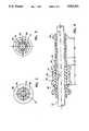
- FIG. 1is an axial cross-section view of a suture sleeve assembly for anchoring the lead body of an implantable medical device in accordance with a preferred embodiment of the present invention, the suture sleeve assembly being shown in its open configuration;
- FIGS. 2 and 3are transverse cross-section views of the assembly of FIG. 1 as seen along the lines 2--2 and 3--3, respectively;
- FIG. 4is an axial cross-section view of the sleeve assembly of FIG. 1 in its closed, lead body-gripping configuration
- FIG. 5is an axial cross-section view of a portion of a suture sleeve assembly in accordance with an alternative embodiment of the invention.
- FIG. 6is a transverse cross-section view of the embodiment of FIG. 5 as seen along the line 6--6.
- FIGS. 1-4show a suture sleeve assembly 10 for gripping and anchoring the lead body 12 of an implantable medical device such as a cardiac pacemaker.
- the lead bodywill typically be of the bipolar coaxial type with which the present invention has particular utility.
- such lead bodiescomprise inner and outer coiled conductors surrounded by an outer tube of soft, implantable insulating material such as silicone.
- the suture sleeve assembly 10includes a tubular member 14 having a central, longitudinal axis 16 and a through bore 18 for receiving the lead body.
- the tubular member 14is preferably fabricated of a soft plastic and includes three portions: a first portion 20, a second portion 22 spaced apart longitudinally from the first portion 20, and a third portion 24 interconnecting the first and second portions.
- the first portion 20 of the tubular body 14has generally cylindrical, concentric outer and inner surfaces 26 and 28, respectively.
- the second portion 22 of the tubular body 14has a generally cylindrical outer surface 30 and a generally cylindrical inner surface 32 concentric with the outer surface.
- the diameter of the outer surface 30 of the second portion 22is greater than the diameter of the outer surface 26 of the first portion.
- the diameter of the inner surface 28 of the second portion 22is less than the diameter of the inner surface of the first portion.
- the diameter of the inner surface 28 of the second portion 22is preferably the same as, or slightly greater, than the outer diameter of the lead body 12 so that the sleeve assembly 10, prior to being secured in place, resists sliding along the lead body when the lead body is held vertically.
- the third portion 24 of the tubular member 14has an outer surface 34 that tapers outwardly, that is, away from the longitudinal axis 18, in the direction from the first portion 20 to the second portion 22 of the tubular body 14 so that the larger diameter end of the tapered portion is adjacent the second portion 22.
- the outer diameter of the larger end of the tapered surface 34is greater than the diameter of the outer surface 30 of the second portion 22.
- a radially extending shoulder surface 36At the junction of the tapered surface 34 and the second portion 22 is a radially extending shoulder surface 36.
- the third or tapered portion 24 of the tubular bodyhas an inner surface 38 which, in accordance with the embodiment under consideration, has a gentle outward taper in the same direction as the taper of the outer surface 34 so that a clearance or relief space 40 is defined between the inner surface 38 and the lead body 12.
- retainer flanges 44 and 46Projecting outwardly from the tubular body, proximate the ends thereof, are retainer flanges 44 and 46.
- a slidable collar 50Disposed about the tubular body is a slidable collar 50 having a bore 52 and planar, radially extending ends 54 and 56.
- the bore 52has a flared end 58 adjacent the end 56 of the collar.
- the tubular bodyis preferably made of a soft implantable elastomer such as silicone or polyurethane.
- the collaris preferably fabricated of a harder implantable plastic such as polysulfone or delrin.
- the collarmay be fabricated of an implantable metal or metallic alloy such as titanium, platinum, platinum-iridium or stainless steel.
- FIG. 1shows the slidable collar 50 in a first or open position in which the collar is on the first portion 20 of the tubular body while FIG. 4 shows the collar 50 in a second or gripping position in which the collar is on the second portion 22 of the tubular body.
- a pair of projecting tabs 60 formed integrally with the tubular bodyinclude eyelets 62 adapted to receive sutures for tying the suture sleeve assembly 10 to the surrounding tissue.
- the suture sleeve assembly 10 in accordance with the embodiment depicted in the drawingsmay have the following dimensions for a lead body whose outer insulation has a diameter of 0.090 inches:
- FIG. 5shows an alternative embodiment in which the inner surface 28 of the first portion 20 of the tubular body is provided with flats 70 or equivalent inwardly directed projections dimensioned so that they lightly engage the outer surface of the lead body 12.
- flats or equivalent projectionscan be used in place of or in combination with an appropriately dimensioned inner surface of the second portion of the tubular body, as already explained.
- the sleeve assembly 10is moved along the lead body to the desired anchoring position.
- the collaris retained in the first position by the flange 44 and tapered portion 34.
- the collaris moved past the tapered portion 34 to its second position.
- the flared portion 58 of the borefacilitates movement of the collar 50 along the tapered portion 34 of the tubular body, the tapered portion 34 being compressed as the collar 50 traverses that portion. Once the collar is past the tapered portion, the tapered portion expands so that with the collar in its second position, shown in FIG.
- the collaris locked in place by the retainer flange 46 at one end and the shoulder 36 at the other end. Because the outer diameter of the second portion 22 of the tubular body is less than the bore diameter of the collar 50, the second portion of the softer tubular body is compressed into gripping engagement with the lead body. Finally, the suture assembly is anchored in place by suturing the assembly to the surrounding tissue, the eyelets 62 being used for this purpose.
- the diameters of the collar bore 52 and second portion 22 of the tubular body 14are such in relation to the diameter of the lead body 12, that compression of the lead insulation is limited in a manner predetermined by the dimensions chosen. Because compression of the lead body is thus limited, the suture sleeve assembly provides reliable, secure gripping of the lead while preventing damage thereto.
Landscapes
- Health & Medical Sciences (AREA)
- Life Sciences & Earth Sciences (AREA)
- Biophysics (AREA)
- Pulmonology (AREA)
- Engineering & Computer Science (AREA)
- Anesthesiology (AREA)
- Biomedical Technology (AREA)
- Heart & Thoracic Surgery (AREA)
- Hematology (AREA)
- Animal Behavior & Ethology (AREA)
- General Health & Medical Sciences (AREA)
- Public Health (AREA)
- Veterinary Medicine (AREA)
- Electrotherapy Devices (AREA)
Abstract
Description
______________________________________ First portion 20: Length: .425 inches Diameter of outer surface: .175 inches Diameter of inner surface: .125 inches Second portion 22: Length: .320 inches Diameter of outer surface: .200 inches Diameter of inner surface: .100 inches Third tapered portion 24: Length: .100 inches Diameter at larger end: .250 inches Collar 50: Length: .300 inches Bore diameter: .185 inches ______________________________________
Claims (11)
Priority Applications (1)
| Application Number | Priority Date | Filing Date | Title |
|---|---|---|---|
| US07/896,942US5242431A (en) | 1992-06-11 | 1992-06-11 | Suture sleeve assembly with slidable compression collar |
Applications Claiming Priority (1)
| Application Number | Priority Date | Filing Date | Title |
|---|---|---|---|
| US07/896,942US5242431A (en) | 1992-06-11 | 1992-06-11 | Suture sleeve assembly with slidable compression collar |
Publications (1)
| Publication Number | Publication Date |
|---|---|
| US5242431Atrue US5242431A (en) | 1993-09-07 |
Family
ID=25407102
Family Applications (1)
| Application Number | Title | Priority Date | Filing Date |
|---|---|---|---|
| US07/896,942Expired - LifetimeUS5242431A (en) | 1992-06-11 | 1992-06-11 | Suture sleeve assembly with slidable compression collar |
Country Status (1)
| Country | Link |
|---|---|
| US (1) | US5242431A (en) |
Cited By (60)
| Publication number | Priority date | Publication date | Assignee | Title |
|---|---|---|---|---|
| US5423763A (en)* | 1993-06-17 | 1995-06-13 | Pacesetter, Inc. | Protective, visible suture sleeve for anchoring transvenous lead bodies |
| US5437650A (en)* | 1993-03-23 | 1995-08-01 | Abbott Laboratories | Securing collar for cannula connector |
| US5584874A (en)* | 1995-04-28 | 1996-12-17 | Medtronic, Inc. | Medical electrical lead having improved anchoring sleeve |
| US5683446A (en)* | 1995-05-25 | 1997-11-04 | Medtronic, Inc. | Medical electrical lead having an anchoring sleeve retaining device |
| US5685858A (en)* | 1995-05-17 | 1997-11-11 | Datascope Corp. | Slidable seal for use with a catheter gard unit |
| US5746722A (en)* | 1997-02-05 | 1998-05-05 | Medtronic, Inc. | Suture sleeve with circumferential lead locking device |
| EP0865799A3 (en)* | 1996-12-26 | 1998-09-30 | JOHNSON & JOHNSON MEDICAL, INC. | Adjustable securing wings |
| US5824032A (en)* | 1996-08-09 | 1998-10-20 | Medtronic Inc. | Medical electrical lead featuring a one piece lead anchoring sleeve with wrap-around locking arms |
| US5827296A (en)* | 1996-09-06 | 1998-10-27 | Medtronic, Inc. | Medical electrical lead |
| WO1998048880A1 (en)* | 1997-04-30 | 1998-11-05 | Medtronic, Inc. | Repositionable medical lead anchor with locking device |
| US5944697A (en)* | 1994-05-31 | 1999-08-31 | Universal Medical Instrument Corp. | Percutaneous catheter introducer |
| US20030199853A1 (en)* | 2002-04-23 | 2003-10-23 | Medtronic Inc. | Implantable medical connector for medical tubing with anchoring features |
| US20040054388A1 (en)* | 2002-07-19 | 2004-03-18 | Osypka Thomas P. | Device and method for delivering cardiac leads |
| US20040059403A1 (en)* | 2002-09-24 | 2004-03-25 | Geriche, Inc. | Suture sleeve |
| US20040152530A1 (en)* | 2003-01-23 | 2004-08-05 | Daley Richard A. | Golf putting device |
| US20040158125A1 (en)* | 2002-09-06 | 2004-08-12 | Aznoian Harold M. | Integrated endoscope and accessory treatment device |
| US20040199234A1 (en)* | 2003-04-07 | 2004-10-07 | Cardiac Pacemakers, Inc. | Extra strength suture sleeve |
| US20040199233A1 (en)* | 2003-04-07 | 2004-10-07 | Cardiac Pacemakers, Inc. | Device and method for a self-attaching suture sleeve |
| US20040220643A1 (en)* | 2001-04-27 | 2004-11-04 | Medtronic, Inc. | Implantable medical device with rechargeable thin-film microbattery power source |
| US20040254623A1 (en)* | 2003-06-12 | 2004-12-16 | Cardiac Pacemakers, Inc. | Star suture sleeve |
| US6901287B2 (en) | 2001-02-09 | 2005-05-31 | Medtronic, Inc. | Implantable therapy delivery element adjustable anchor |
| US20050251102A1 (en)* | 2003-09-26 | 2005-11-10 | Michael Hegland | Catheter connection systems and methods |
| US20060127158A1 (en)* | 2004-10-21 | 2006-06-15 | Medtronic, Inc. | Implantable electrical lead retention system and method |
| US20060149293A1 (en)* | 2004-11-29 | 2006-07-06 | Eric King | Reduced-friction catheter introducer and method of manufacturing and using the same |
| US20060195066A1 (en)* | 2005-02-14 | 2006-08-31 | Medtronic, Inc. | Strain relief device and connector assemblies incorporating same |
| DE102005015487B3 (en)* | 2005-04-05 | 2006-12-07 | Osypka, Peter, Dr.-Ing. | Device has slitted casing with axial inner hole in longitudinal direction and single slit in radial direction and when pressed together electrode is connected firmly to casing |
| US7184841B1 (en) | 2004-08-19 | 2007-02-27 | Cardiac Pacemakers, Inc. | Pacing lead stabilizer |
| US20070050005A1 (en)* | 2005-08-26 | 2007-03-01 | Advanced Bionics Corporation | Lead anchor for implantable stimulation devices and methods of manufacture and use |
| US7220266B2 (en) | 2000-05-19 | 2007-05-22 | C. R. Bard, Inc. | Tissue capturing and suturing device and method |
| US20070123923A1 (en)* | 2005-11-30 | 2007-05-31 | Lindstrom Curtis C | Implantable medical device minimizing rotation and dislocation |
| US20070123825A1 (en)* | 2004-11-29 | 2007-05-31 | Eric King | Reduced-friction catheter introducer and method of manufacturing and using the same |
| US20080103476A1 (en)* | 2004-05-13 | 2008-05-01 | Medtronic, Inc. | Medical tubing connector assembly incorporating strain relief sleeve |
| US7399304B2 (en) | 2000-03-03 | 2008-07-15 | C.R. Bard, Inc. | Endoscopic tissue apposition device with multiple suction ports |
| US20080243220A1 (en)* | 2007-03-28 | 2008-10-02 | Advanced Bionics Corporation | Lead anchor for implantable stimulation devices |
| US20080262588A1 (en)* | 2004-08-16 | 2008-10-23 | Cardiac Pacemakers, Inc. | Lead assembly and methods including a push tube |
| US20090125058A1 (en)* | 2007-11-09 | 2009-05-14 | Bodner Jeffrey P | Lead stabilizer with retention features |
| US20090125059A1 (en)* | 2007-11-09 | 2009-05-14 | Verzal Kevin E | Compression member suture sleeve |
| WO2009120116A1 (en)* | 2008-03-28 | 2009-10-01 | St. Jude Medical Ab | A suture sleeve and a method for positioning a suture sleeve and a lead in relation to each other |
| US20090254151A1 (en)* | 2008-04-02 | 2009-10-08 | Boston Scientific Neuromodulation Corporation | Lead anchor for implantable devices and methods of manufacture and use |
| US20110009935A1 (en)* | 2009-07-10 | 2011-01-13 | Greatbatch Ltd. | Reinforced Suture Sleeve |
| US20110060395A1 (en)* | 2009-09-09 | 2011-03-10 | Kurt Cantlon | Key locking anchoring device for implanted lead |
| US7993368B2 (en) | 2003-03-13 | 2011-08-09 | C.R. Bard, Inc. | Suture clips, delivery devices and methods |
| US8075573B2 (en) | 2003-05-16 | 2011-12-13 | C.R. Bard, Inc. | Single intubation, multi-stitch endoscopic suturing system |
| US8105351B2 (en) | 2001-05-18 | 2012-01-31 | C.R. Bard, Inc. | Method of promoting tissue adhesion |
| US8403890B2 (en) | 2004-11-29 | 2013-03-26 | C. R. Bard, Inc. | Reduced friction catheter introducer and method of manufacturing and using the same |
| US8608702B2 (en) | 2007-10-19 | 2013-12-17 | C. R. Bard, Inc. | Introducer including shaped distal region |
| US8649881B2 (en) | 2009-05-28 | 2014-02-11 | St. Jude Medical Ab | Suture sleeve and a method for manufacturing a suture sleeve |
| US8720065B2 (en) | 2004-04-30 | 2014-05-13 | C. R. Bard, Inc. | Valved sheath introducer for venous cannulation |
| US20140276986A1 (en)* | 2013-03-15 | 2014-09-18 | Carine Hoarau | Anastomotic device and method |
| US8882785B2 (en) | 2008-09-29 | 2014-11-11 | Paul C. DiCesare | Endoscopic suturing device |
| US8897892B2 (en) | 2012-10-29 | 2014-11-25 | Cardiac Pacemakers, Inc. | Suture sleeves having exterior surface tear resistance |
| US8926564B2 (en) | 2004-11-29 | 2015-01-06 | C. R. Bard, Inc. | Catheter introducer including a valve and valve actuator |
| US9005220B2 (en) | 2006-04-04 | 2015-04-14 | C.R. Bard, Inc. | Suturing devices and methods with energy emitting elements |
| US20150320991A1 (en)* | 2012-06-28 | 2015-11-12 | Plugmed Heart | Percutaneous connection device with a socket and with an extension member |
| US9486622B2 (en) | 2012-11-08 | 2016-11-08 | Cardiac Pacemakers, Inc. | Fixation and strain relief element for temporary therapy delivery device |
| US9585654B2 (en) | 2012-05-01 | 2017-03-07 | Dean & Webb, LLC | Segmentally rigid suture and suturing technique |
| US10286208B2 (en) | 2015-05-20 | 2019-05-14 | Cardiac Pacemakers, Inc. | Fully integrated lead stabilizer for medical electrical leads and methods of attachment |
| US10603483B2 (en) | 2016-04-28 | 2020-03-31 | Medtronic, Inc. | Lead implant fixation mechanism |
| US11235121B2 (en) | 2015-11-06 | 2022-02-01 | Fisher & Paykel Healthcare Limited | Apparatus for use in a respiratory support system |
| US20230392732A1 (en)* | 2020-11-20 | 2023-12-07 | Oetiker Ny, Inc. | Fluid connection assembly |
Citations (16)
| Publication number | Priority date | Publication date | Assignee | Title |
|---|---|---|---|---|
| US3888523A (en)* | 1973-05-10 | 1975-06-10 | Merit Plastics Inc | Non-threaded tubing connector |
| US4088349A (en)* | 1977-04-04 | 1978-05-09 | Guest Manuel T | Hose connection employing relatively slidable parts |
| US4114626A (en)* | 1975-01-30 | 1978-09-19 | Beran Anthony V | Intubation set |
| US4114930A (en)* | 1976-06-28 | 1978-09-19 | The Boeing Company | Swaged tube coupling |
| US4276882A (en)* | 1979-05-18 | 1981-07-07 | Medtronic, Inc. | Lead anchoring device |
| US4387727A (en)* | 1981-03-30 | 1983-06-14 | Medtronic, Inc. | Coaxial service kit |
| US4516584A (en)* | 1983-01-07 | 1985-05-14 | Cordis Corporation | Suture collar |
| US4526572A (en)* | 1982-06-30 | 1985-07-02 | The Boots Company Plc | Medical connector |
| US4538623A (en)* | 1984-04-09 | 1985-09-03 | Medtronic, Inc. | Thread electrode assembly |
| US4553961A (en)* | 1984-04-18 | 1985-11-19 | Cordis Corporation | Suture sleeve with structure for enhancing pacing lead gripping |
| US4616855A (en)* | 1984-10-29 | 1986-10-14 | Ruhle James L | Threadless nonrotating steel coupling system |
| US4672979A (en)* | 1986-01-30 | 1987-06-16 | Cordis Corporation | Suture sleeve assembly |
| US4683895A (en)* | 1985-07-25 | 1987-08-04 | Cordis Corporation | Suture sleeve anchoring device |
| US4769897A (en)* | 1983-08-25 | 1988-09-13 | Enron Corp. | Method for forming a press-fitted pipe joint |
| US5111858A (en)* | 1990-12-24 | 1992-05-12 | Ford Motor Company | Interengageable plastic fuel flange and plastic filler tube |
| US5131632A (en)* | 1991-10-28 | 1992-07-21 | Olson Darwin B | Quick coupling pipe connecting structure with body-tapered sleeve |
- 1992
- 1992-06-11USUS07/896,942patent/US5242431A/ennot_activeExpired - Lifetime
Patent Citations (16)
| Publication number | Priority date | Publication date | Assignee | Title |
|---|---|---|---|---|
| US3888523A (en)* | 1973-05-10 | 1975-06-10 | Merit Plastics Inc | Non-threaded tubing connector |
| US4114626A (en)* | 1975-01-30 | 1978-09-19 | Beran Anthony V | Intubation set |
| US4114930A (en)* | 1976-06-28 | 1978-09-19 | The Boeing Company | Swaged tube coupling |
| US4088349A (en)* | 1977-04-04 | 1978-05-09 | Guest Manuel T | Hose connection employing relatively slidable parts |
| US4276882A (en)* | 1979-05-18 | 1981-07-07 | Medtronic, Inc. | Lead anchoring device |
| US4387727A (en)* | 1981-03-30 | 1983-06-14 | Medtronic, Inc. | Coaxial service kit |
| US4526572A (en)* | 1982-06-30 | 1985-07-02 | The Boots Company Plc | Medical connector |
| US4516584A (en)* | 1983-01-07 | 1985-05-14 | Cordis Corporation | Suture collar |
| US4769897A (en)* | 1983-08-25 | 1988-09-13 | Enron Corp. | Method for forming a press-fitted pipe joint |
| US4538623A (en)* | 1984-04-09 | 1985-09-03 | Medtronic, Inc. | Thread electrode assembly |
| US4553961A (en)* | 1984-04-18 | 1985-11-19 | Cordis Corporation | Suture sleeve with structure for enhancing pacing lead gripping |
| US4616855A (en)* | 1984-10-29 | 1986-10-14 | Ruhle James L | Threadless nonrotating steel coupling system |
| US4683895A (en)* | 1985-07-25 | 1987-08-04 | Cordis Corporation | Suture sleeve anchoring device |
| US4672979A (en)* | 1986-01-30 | 1987-06-16 | Cordis Corporation | Suture sleeve assembly |
| US5111858A (en)* | 1990-12-24 | 1992-05-12 | Ford Motor Company | Interengageable plastic fuel flange and plastic filler tube |
| US5131632A (en)* | 1991-10-28 | 1992-07-21 | Olson Darwin B | Quick coupling pipe connecting structure with body-tapered sleeve |
Cited By (101)
| Publication number | Priority date | Publication date | Assignee | Title |
|---|---|---|---|---|
| US5437650A (en)* | 1993-03-23 | 1995-08-01 | Abbott Laboratories | Securing collar for cannula connector |
| US5507733A (en)* | 1993-03-23 | 1996-04-16 | Abbott Laboratories | Securable collar for fluid connector |
| US5423763A (en)* | 1993-06-17 | 1995-06-13 | Pacesetter, Inc. | Protective, visible suture sleeve for anchoring transvenous lead bodies |
| US5944697A (en)* | 1994-05-31 | 1999-08-31 | Universal Medical Instrument Corp. | Percutaneous catheter introducer |
| US5584874A (en)* | 1995-04-28 | 1996-12-17 | Medtronic, Inc. | Medical electrical lead having improved anchoring sleeve |
| US5685858A (en)* | 1995-05-17 | 1997-11-11 | Datascope Corp. | Slidable seal for use with a catheter gard unit |
| US5683446A (en)* | 1995-05-25 | 1997-11-04 | Medtronic, Inc. | Medical electrical lead having an anchoring sleeve retaining device |
| US5824032A (en)* | 1996-08-09 | 1998-10-20 | Medtronic Inc. | Medical electrical lead featuring a one piece lead anchoring sleeve with wrap-around locking arms |
| US5827296A (en)* | 1996-09-06 | 1998-10-27 | Medtronic, Inc. | Medical electrical lead |
| EP0865799A3 (en)* | 1996-12-26 | 1998-09-30 | JOHNSON & JOHNSON MEDICAL, INC. | Adjustable securing wings |
| US5746722A (en)* | 1997-02-05 | 1998-05-05 | Medtronic, Inc. | Suture sleeve with circumferential lead locking device |
| WO1998048880A1 (en)* | 1997-04-30 | 1998-11-05 | Medtronic, Inc. | Repositionable medical lead anchor with locking device |
| US8992570B2 (en) | 2000-03-03 | 2015-03-31 | C.R. Bard, Inc. | Suture clips, delivery devices and methods |
| US8100920B2 (en) | 2000-03-03 | 2012-01-24 | C.R. Bard, Inc. | Endoscopic tissue apposition device with multiple suction ports |
| US7399304B2 (en) | 2000-03-03 | 2008-07-15 | C.R. Bard, Inc. | Endoscopic tissue apposition device with multiple suction ports |
| US7220266B2 (en) | 2000-05-19 | 2007-05-22 | C. R. Bard, Inc. | Tissue capturing and suturing device and method |
| US7951157B2 (en) | 2000-05-19 | 2011-05-31 | C.R. Bard, Inc. | Tissue capturing and suturing device and method |
| US6901287B2 (en) | 2001-02-09 | 2005-05-31 | Medtronic, Inc. | Implantable therapy delivery element adjustable anchor |
| US20040220643A1 (en)* | 2001-04-27 | 2004-11-04 | Medtronic, Inc. | Implantable medical device with rechargeable thin-film microbattery power source |
| US8105351B2 (en) | 2001-05-18 | 2012-01-31 | C.R. Bard, Inc. | Method of promoting tissue adhesion |
| US20060084941A1 (en)* | 2002-04-23 | 2006-04-20 | Medtronic, Inc. | Implantable medical connector for medical tubing with anchoring features |
| US6997919B2 (en) | 2002-04-23 | 2006-02-14 | Medtronic, Inc. | Implantable medical connector for medical tubing with anchoring features |
| US20060084940A1 (en)* | 2002-04-23 | 2006-04-20 | Medtronic, Inc. | Implantable medical connector for medical tubing with anchoring features |
| US20030199853A1 (en)* | 2002-04-23 | 2003-10-23 | Medtronic Inc. | Implantable medical connector for medical tubing with anchoring features |
| US20040054388A1 (en)* | 2002-07-19 | 2004-03-18 | Osypka Thomas P. | Device and method for delivering cardiac leads |
| US7151965B2 (en)* | 2002-07-19 | 2006-12-19 | Oscor Inc. | Device and method for delivering cardiac leads |
| US20040158125A1 (en)* | 2002-09-06 | 2004-08-12 | Aznoian Harold M. | Integrated endoscope and accessory treatment device |
| US8057386B2 (en) | 2002-09-06 | 2011-11-15 | C.R. Bard, Inc. | Integrated endoscope and accessory treatment device |
| US8206284B2 (en) | 2002-09-06 | 2012-06-26 | C.R. Bard, Inc. | Integrated endoscope and accessory treatment device |
| US20040059403A1 (en)* | 2002-09-24 | 2004-03-25 | Geriche, Inc. | Suture sleeve |
| US20040152530A1 (en)* | 2003-01-23 | 2004-08-05 | Daley Richard A. | Golf putting device |
| US7993368B2 (en) | 2003-03-13 | 2011-08-09 | C.R. Bard, Inc. | Suture clips, delivery devices and methods |
| US7218972B2 (en) | 2003-04-07 | 2007-05-15 | Cardiac Pacemakers, Inc. | Extra strength suture sleeve |
| US20040199234A1 (en)* | 2003-04-07 | 2004-10-07 | Cardiac Pacemakers, Inc. | Extra strength suture sleeve |
| US20040199233A1 (en)* | 2003-04-07 | 2004-10-07 | Cardiac Pacemakers, Inc. | Device and method for a self-attaching suture sleeve |
| US7242986B2 (en)* | 2003-04-07 | 2007-07-10 | Cardiac Pacemakers, Inc. | Device and method for a self-attaching suture sleeve |
| US8075573B2 (en) | 2003-05-16 | 2011-12-13 | C.R. Bard, Inc. | Single intubation, multi-stitch endoscopic suturing system |
| US20040254623A1 (en)* | 2003-06-12 | 2004-12-16 | Cardiac Pacemakers, Inc. | Star suture sleeve |
| US20050251102A1 (en)* | 2003-09-26 | 2005-11-10 | Michael Hegland | Catheter connection systems and methods |
| US10307182B2 (en) | 2004-04-30 | 2019-06-04 | C. R. Bard, Inc. | Valved sheath introducer for venous cannulation |
| US8720065B2 (en) | 2004-04-30 | 2014-05-13 | C. R. Bard, Inc. | Valved sheath introducer for venous cannulation |
| US9108033B2 (en) | 2004-04-30 | 2015-08-18 | C. R. Bard, Inc. | Valved sheath introducer for venous cannulation |
| US20080103476A1 (en)* | 2004-05-13 | 2008-05-01 | Medtronic, Inc. | Medical tubing connector assembly incorporating strain relief sleeve |
| US20080262588A1 (en)* | 2004-08-16 | 2008-10-23 | Cardiac Pacemakers, Inc. | Lead assembly and methods including a push tube |
| US7920927B2 (en)* | 2004-08-16 | 2011-04-05 | Cardiac Pacemakers, Inc. | Lead assembly and methods including a push tube |
| US8396569B2 (en) | 2004-08-16 | 2013-03-12 | Cardiac Pacemakers, Inc. | Lead assembly and methods including a push tube |
| US20100228263A1 (en)* | 2004-08-16 | 2010-09-09 | Zarembo Paul E | Lead assembly and methods including a push tube |
| US7184841B1 (en) | 2004-08-19 | 2007-02-27 | Cardiac Pacemakers, Inc. | Pacing lead stabilizer |
| US20060127158A1 (en)* | 2004-10-21 | 2006-06-15 | Medtronic, Inc. | Implantable electrical lead retention system and method |
| US8403890B2 (en) | 2004-11-29 | 2013-03-26 | C. R. Bard, Inc. | Reduced friction catheter introducer and method of manufacturing and using the same |
| US9597483B2 (en) | 2004-11-29 | 2017-03-21 | C. R. Bard, Inc. | Reduced-friction catheter introducer and method of manufacturing and using the same |
| US8932260B2 (en) | 2004-11-29 | 2015-01-13 | C. R. Bard, Inc. | Reduced-friction catheter introducer and method of manufacturing and using the same |
| US8926564B2 (en) | 2004-11-29 | 2015-01-06 | C. R. Bard, Inc. | Catheter introducer including a valve and valve actuator |
| US9278188B2 (en) | 2004-11-29 | 2016-03-08 | C. R. Bard, Inc. | Catheter introducer including a valve and valve actuator |
| US9078998B2 (en) | 2004-11-29 | 2015-07-14 | C. R. Bard, Inc. | Catheter introducer including a valve and valve actuator |
| US9283351B2 (en) | 2004-11-29 | 2016-03-15 | C. R. Bard, Inc. | Reduced friction catheter introducer and method of manufacturing and using the same |
| US9101737B2 (en) | 2004-11-29 | 2015-08-11 | C. R. Bard, Inc. | Reduced friction catheter introducer and method of manufacturing and using the same |
| US20070123825A1 (en)* | 2004-11-29 | 2007-05-31 | Eric King | Reduced-friction catheter introducer and method of manufacturing and using the same |
| US10398879B2 (en) | 2004-11-29 | 2019-09-03 | C. R. Bard, Inc. | Reduced-friction catheter introducer and method of manufacturing and using the same |
| US20060149293A1 (en)* | 2004-11-29 | 2006-07-06 | Eric King | Reduced-friction catheter introducer and method of manufacturing and using the same |
| US20060195066A1 (en)* | 2005-02-14 | 2006-08-31 | Medtronic, Inc. | Strain relief device and connector assemblies incorporating same |
| US7537245B2 (en)* | 2005-02-14 | 2009-05-26 | Medtronic, Inc. | Strain relief device and connector assemblies incorporating same |
| DE102005015487B3 (en)* | 2005-04-05 | 2006-12-07 | Osypka, Peter, Dr.-Ing. | Device has slitted casing with axial inner hole in longitudinal direction and single slit in radial direction and when pressed together electrode is connected firmly to casing |
| US7831313B2 (en)* | 2005-08-26 | 2010-11-09 | Boston Scientific Neuromodulation Corporation | Lead anchor for implantable stimulation devices and methods of manufacture and use |
| US20070050005A1 (en)* | 2005-08-26 | 2007-03-01 | Advanced Bionics Corporation | Lead anchor for implantable stimulation devices and methods of manufacture and use |
| US20070123923A1 (en)* | 2005-11-30 | 2007-05-31 | Lindstrom Curtis C | Implantable medical device minimizing rotation and dislocation |
| US9005220B2 (en) | 2006-04-04 | 2015-04-14 | C.R. Bard, Inc. | Suturing devices and methods with energy emitting elements |
| US20080243220A1 (en)* | 2007-03-28 | 2008-10-02 | Advanced Bionics Corporation | Lead anchor for implantable stimulation devices |
| US7899553B2 (en) | 2007-03-28 | 2011-03-01 | Boston Scientific Neuromodulation Corporation | Lead anchor for implantable stimulation devices |
| US8608702B2 (en) | 2007-10-19 | 2013-12-17 | C. R. Bard, Inc. | Introducer including shaped distal region |
| US20090125060A1 (en)* | 2007-11-09 | 2009-05-14 | Rivard Adam J | Compression control lead anchoring device |
| US20090125061A1 (en)* | 2007-11-09 | 2009-05-14 | Rivard Adam J | Pre-selected compression lead anchoring device |
| US8249719B2 (en) | 2007-11-09 | 2012-08-21 | Cardiac Pacemakers, Inc. | Lead stabilizer with retention features |
| US20090125058A1 (en)* | 2007-11-09 | 2009-05-14 | Bodner Jeffrey P | Lead stabilizer with retention features |
| US20090125059A1 (en)* | 2007-11-09 | 2009-05-14 | Verzal Kevin E | Compression member suture sleeve |
| US8126569B2 (en) | 2007-11-09 | 2012-02-28 | Cardiac Pacemakers, Inc. | Compression control lead anchoring device |
| US8249720B2 (en) | 2007-11-09 | 2012-08-21 | Cardiac Pacemakers, Inc. | Compression member suture sleeve |
| US8271096B2 (en) | 2007-11-09 | 2012-09-18 | Cardiac Pacemakers, Inc. | Pre-selected compression lead anchoring device |
| US20100324569A1 (en)* | 2008-03-28 | 2010-12-23 | St. Jude Medical Ab | Suture sleeve and a method for positioning a suture sleeve and a lead in relation to each other |
| WO2009120116A1 (en)* | 2008-03-28 | 2009-10-01 | St. Jude Medical Ab | A suture sleeve and a method for positioning a suture sleeve and a lead in relation to each other |
| US20090254151A1 (en)* | 2008-04-02 | 2009-10-08 | Boston Scientific Neuromodulation Corporation | Lead anchor for implantable devices and methods of manufacture and use |
| US9320891B2 (en) | 2008-04-02 | 2016-04-26 | Boston Scientific Neuromodulation Corporation | Lead anchor for implantable devices and methods of manufacture and use |
| US8882785B2 (en) | 2008-09-29 | 2014-11-11 | Paul C. DiCesare | Endoscopic suturing device |
| US8649881B2 (en) | 2009-05-28 | 2014-02-11 | St. Jude Medical Ab | Suture sleeve and a method for manufacturing a suture sleeve |
| US8958891B2 (en) | 2009-07-10 | 2015-02-17 | Greatbatch Ltd. | Reinforced suture sleeve |
| US20110009935A1 (en)* | 2009-07-10 | 2011-01-13 | Greatbatch Ltd. | Reinforced Suture Sleeve |
| US20110060395A1 (en)* | 2009-09-09 | 2011-03-10 | Kurt Cantlon | Key locking anchoring device for implanted lead |
| US8489208B2 (en)* | 2009-09-09 | 2013-07-16 | Advanced Neuromodulation Systems, Inc. | Key locking anchoring device for implanted lead |
| US9585654B2 (en) | 2012-05-01 | 2017-03-07 | Dean & Webb, LLC | Segmentally rigid suture and suturing technique |
| US10220197B2 (en)* | 2012-06-28 | 2019-03-05 | Plugmed Heart | Percutaneous connection device with a socket and with an extension member |
| US20150320991A1 (en)* | 2012-06-28 | 2015-11-12 | Plugmed Heart | Percutaneous connection device with a socket and with an extension member |
| US8897892B2 (en) | 2012-10-29 | 2014-11-25 | Cardiac Pacemakers, Inc. | Suture sleeves having exterior surface tear resistance |
| US9486622B2 (en) | 2012-11-08 | 2016-11-08 | Cardiac Pacemakers, Inc. | Fixation and strain relief element for temporary therapy delivery device |
| US20140276986A1 (en)* | 2013-03-15 | 2014-09-18 | Carine Hoarau | Anastomotic device and method |
| US10286208B2 (en) | 2015-05-20 | 2019-05-14 | Cardiac Pacemakers, Inc. | Fully integrated lead stabilizer for medical electrical leads and methods of attachment |
| US11235121B2 (en) | 2015-11-06 | 2022-02-01 | Fisher & Paykel Healthcare Limited | Apparatus for use in a respiratory support system |
| US11717630B2 (en) | 2015-11-06 | 2023-08-08 | Fisher & Paykel Healthcare Limited | Apparatus for use in a respiratory support system |
| US10603483B2 (en) | 2016-04-28 | 2020-03-31 | Medtronic, Inc. | Lead implant fixation mechanism |
| US11559679B2 (en) | 2016-04-28 | 2023-01-24 | Medtronic, Inc. | Lead implant fixation mechanism |
| US20230392732A1 (en)* | 2020-11-20 | 2023-12-07 | Oetiker Ny, Inc. | Fluid connection assembly |
| US12222057B2 (en)* | 2020-11-20 | 2025-02-11 | Oetiker Ny, Inc. | Fluid connection assembly |
Similar Documents
| Publication | Publication Date | Title |
|---|---|---|
| US5242431A (en) | Suture sleeve assembly with slidable compression collar | |
| US5152298A (en) | Threaded suture sleeve | |
| US4672979A (en) | Suture sleeve assembly | |
| US5129405A (en) | Vein suture collar | |
| US5107856A (en) | Multiple lead suture sleeve | |
| US6141593A (en) | Cardiac lead with ETEE coated DBS coil | |
| US5746722A (en) | Suture sleeve with circumferential lead locking device | |
| US8249720B2 (en) | Compression member suture sleeve | |
| AU655373B2 (en) | Suture sleeve with lead locking device | |
| US4516584A (en) | Suture collar | |
| US5645585A (en) | Cochlear electrode implant assembly with positioning system therefor | |
| US5628780A (en) | Protective, visible suture sleeve for anchoring transvenous lead bodies | |
| US4411276A (en) | Implantable multiple connector | |
| EP0662853B1 (en) | An implantable lead | |
| US4614395A (en) | Quick connector to medical electrical lead | |
| US4579120A (en) | Strain relief for percutaneous lead | |
| US5476493A (en) | Implantable lead having self-locking suture sleeve | |
| US5584874A (en) | Medical electrical lead having improved anchoring sleeve | |
| US5376108A (en) | Electrode lead anchoring apparatus and method employing dual suture collars | |
| US4683895A (en) | Suture sleeve anchoring device | |
| US7359756B2 (en) | Method of removing an elongated structure implanted in biological tissue | |
| US5603730A (en) | Suture sleeve for implantable lead | |
| EP0037223A1 (en) | A body implantable lead having a ring electrode, and a process for making same | |
| JP2003515358A (en) | Expandable / contractible fixed cardiac pacemaker lead | |
| EP0438510A1 (en) | BIDIRECTIONAL SCREW-SHAPED ELECTRODE FOR STIMULATING THE NERVES. |
Legal Events
| Date | Code | Title | Description |
|---|---|---|---|
| AS | Assignment | Owner name:SIEMENS PACESTTER, INC., A CORP. OF DE, CALIFORNIA Free format text:ASSIGNMENT OF ASSIGNORS INTEREST.;ASSIGNOR:KRISTIANSEN, JEFFREY C.;REEL/FRAME:006175/0930 Effective date:19920611 Owner name:SIEMENS-ELEMA AB, A SWEDISH CORP., SWEDEN Free format text:ASSIGNMENT OF ASSIGNORS INTEREST.;ASSIGNOR:KRISTIANSEN, JEFFREY C.;REEL/FRAME:006175/0930 Effective date:19920611 Owner name:SIEMENS AKTIENGESELLSCHAFT, A CORP. OF FED. REP. O Free format text:ASSIGNMENT OF ASSIGNORS INTEREST.;ASSIGNOR:KRISTIANSEN, JEFFREY C.;REEL/FRAME:006175/0930 Effective date:19920611 | |
| STCF | Information on status: patent grant | Free format text:PATENTED CASE | |
| AS | Assignment | Owner name:PACESETTER, INC., CALIFORNIA Free format text:ASSIGNMENT OF ASSIGNORS INTEREST;ASSIGNOR:SIEMENS PACESETTER, INC.;REEL/FRAME:007388/0042 Effective date:19940930 | |
| CC | Certificate of correction | ||
| FPAY | Fee payment | Year of fee payment:4 | |
| FEPP | Fee payment procedure | Free format text:PAYOR NUMBER ASSIGNED (ORIGINAL EVENT CODE: ASPN); ENTITY STATUS OF PATENT OWNER: LARGE ENTITY | |
| FPAY | Fee payment | Year of fee payment:8 | |
| FPAY | Fee payment | Year of fee payment:12 |