US5241941A - Ignition coil - Google Patents
Ignition coilDownload PDFInfo
- Publication number
- US5241941A US5241941AUS07/939,800US93980092AUS5241941AUS 5241941 AUS5241941 AUS 5241941AUS 93980092 AUS93980092 AUS 93980092AUS 5241941 AUS5241941 AUS 5241941A
- Authority
- US
- United States
- Prior art keywords
- shaped
- core member
- coil
- permanent magnet
- shaped core
- Prior art date
- Legal status (The legal status is an assumption and is not a legal conclusion. Google has not performed a legal analysis and makes no representation as to the accuracy of the status listed.)
- Expired - Lifetime
Links
- XEEYBQQBJWHFJM-UHFFFAOYSA-NIronChemical group[Fe]XEEYBQQBJWHFJM-UHFFFAOYSA-N0.000claimsabstractdescription21
- 239000000696magnetic materialSubstances0.000claimsabstractdescription16
- 238000004804windingMethods0.000claimsdescription37
- 239000000463materialSubstances0.000claimsdescription25
- 239000011159matrix materialSubstances0.000claimsdescription11
- 229910052779NeodymiumInorganic materials0.000claimsdescription7
- 229910052772SamariumInorganic materials0.000claimsdescription7
- QEFYFXOXNSNQGX-UHFFFAOYSA-Nneodymium atomChemical compound[Nd]QEFYFXOXNSNQGX-UHFFFAOYSA-N0.000claimsdescription6
- KZUNJOHGWZRPMI-UHFFFAOYSA-Nsamarium atomChemical compound[Sm]KZUNJOHGWZRPMI-UHFFFAOYSA-N0.000claimsdescription6
- 230000004907fluxEffects0.000claimsdescription5
- 238000002347injectionMethods0.000claimsdescription5
- 239000007924injectionSubstances0.000claimsdescription5
- 239000004033plasticSubstances0.000claimsdescription5
- 238000002485combustion reactionMethods0.000claimsdescription4
- 238000006073displacement reactionMethods0.000claimsdescription4
- 230000014759maintenance of locationEffects0.000claimsdescription4
- 238000004519manufacturing processMethods0.000claimsdescription4
- 238000003475laminationMethods0.000claimsdescription3
- 239000002991molded plasticSubstances0.000claimsdescription3
- 230000001154acute effectEffects0.000claims4
- 230000000694effectsEffects0.000claims2
- 229910052742ironInorganic materials0.000claims1
- 230000008030eliminationEffects0.000abstract1
- 238000003379elimination reactionMethods0.000abstract1
- 229910000831SteelInorganic materials0.000description7
- 239000010959steelSubstances0.000description7
- 239000004593EpoxySubstances0.000description5
- 230000000712assemblyEffects0.000description5
- 238000000429assemblyMethods0.000description5
- 238000004382pottingMethods0.000description4
- 229910052761rare earth metalInorganic materials0.000description4
- 150000002910rare earth metalsChemical class0.000description4
- 239000004677NylonSubstances0.000description3
- 238000010276constructionMethods0.000description3
- 229920001778nylonPolymers0.000description3
- 230000008901benefitEffects0.000description2
- 230000002708enhancing effectEffects0.000description2
- 239000000945fillerSubstances0.000description2
- 238000003780insertionMethods0.000description2
- 230000037431insertionEffects0.000description2
- 238000009413insulationMethods0.000description2
- 230000000717retained effectEffects0.000description2
- 230000008646thermal stressEffects0.000description2
- 241001272720Medialuna californiensisSpecies0.000description1
- 239000004743PolypropyleneSubstances0.000description1
- 230000002159abnormal effectEffects0.000description1
- 239000000956alloySubstances0.000description1
- 229910045601alloyInorganic materials0.000description1
- 239000011230binding agentSubstances0.000description1
- 239000002131composite materialSubstances0.000description1
- 238000005336crackingMethods0.000description1
- 239000011810insulating materialSubstances0.000description1
- 238000000034methodMethods0.000description1
- -1polypropylenePolymers0.000description1
- 229920001155polypropylenePolymers0.000description1
- 239000012255powdered metalSubstances0.000description1
- 238000005476solderingMethods0.000description1
- 230000035882stressEffects0.000description1
Images


Classifications
- F—MECHANICAL ENGINEERING; LIGHTING; HEATING; WEAPONS; BLASTING
- F02—COMBUSTION ENGINES; HOT-GAS OR COMBUSTION-PRODUCT ENGINE PLANTS
- F02P—IGNITION, OTHER THAN COMPRESSION IGNITION, FOR INTERNAL-COMBUSTION ENGINES; TESTING OF IGNITION TIMING IN COMPRESSION-IGNITION ENGINES
- F02P13/00—Sparking plugs structurally combined with other parts of internal-combustion engines
- H—ELECTRICITY
- H01—ELECTRIC ELEMENTS
- H01F—MAGNETS; INDUCTANCES; TRANSFORMERS; SELECTION OF MATERIALS FOR THEIR MAGNETIC PROPERTIES
- H01F38/00—Adaptations of transformers or inductances for specific applications or functions
- H01F38/12—Ignition, e.g. for IC engines
Definitions
- This inventionrelates to ignition coils, particularly modularly constructed, permanent magnet-type ignition coils for vehicular ignition systems.
- an ignition coil or coilshaving a C-shaped iron core within a non-conductive housing, with the primary and secondary windings wound on individual bobbins inter-nested within one another and lying within the boundaries of the C-shaped iron core.
- the coilis filled with epoxy potting material or other insulating material as a final step in the process.
- epoxypotting material
- the gap between the ends of the legs of the C-shaped iron coreare referred to as an "air gap”.
- air gapthe gap between the ends of the legs of the C-shaped iron core
- the efficiencycan be increased and compactness of the overall coil structure, including the housing, can be reduced by nearly filling the air gap portion of the aforementioned iron core with a permanent magnet.
- Such a coil constructionis shown in U.S. Pat. No. 4,990,881.
- a permanent magnet-type ignition coilhaving preferably no air gap and also assuring that should there be a small air gap due to component tolerance stack-up it will be in a predetermined location thereby enhancing considerably the efficiency and power output of the coil. This allows for a substantial reduction in the size of the overall unit for acquiring the same unit power output.
- a further feature of the subject inventionis the design and use of a permanent magnet composed of a bonded magnetic material, which is less than fully dense, made of these most recently available rare earth, high energy materials such as samarium and neodymium, thereby providing a material which is equally effective, but far less expensive than the fully dense permanent magnet heretofore used, and having the added benefit that its thickness, including the magnetizing alloy elements Nd or Sm or equivalent, provides for less expensive fabrication and easier handling during assembly of the coil.
- the subject inventiontherefore contemplates an improved permanent magnet-type electromagnetic coil of the lightest weight and smallest size for its performance.
- the inventionfurther contemplates an electromagnetic ignition coil of the type described utilizing a rare earth, high energy magnetic material for the permanent magnet which is substantially less than fully dense, and therefore is less expensive than a magnet made of fully dense material and also completely eliminates the need for any air gap between the permanent magnet and the iron core, which in turn results in the maximum efficiency of the permanent magnet-type coil design.
- the inventionfurther contemplates an ignition coil of the type described above wherein the permanent magnet member includes means for virtually eliminating the air gap throughout the complete range of dimensional tolerances on each of the coil components contributing to the existence or non-existence of the air gap.
- the inventionfurther contemplates an ignition coil assembly of modular construction and wherein the construction of the components provides means for insulating the iron core thermally from the epoxy filler material, such that the possibility of thermal stress cracks between the core and the primary and/or secondary windings are eliminated, and wherein the bobbin for both the primary and secondary windings are cylindrical, thereby allowing the winding of the coils onto the bobbin with even tension, and wherein the cylindrical bobbin for the primary winding is provided with flow-through passages thereby allowing the epoxy material to quickly and completely fill and insulate the windings from both sides of the bobbin, and wherein the terminals leading to and from the primary and secondary coils require no soldering, and wherein the retainer bushings which are injection-molded into the coil housing include means for precluding the relative displacement of the bushing with respect to the housing in both the radial and axial directions.
- the inventionfurther contemplates a boot at the secondary coil output terminal end of the coil having means for retaining the retention spring within the boot but requiring no mechanical connection between the boot and the spring, and likewise allowing the customary insertion and retention of the spark plug within the boot.
- FIG. 1is a general perspective view of the ignition coil assembly in accordance with the present invention and with potting material removed and the primary connector assembly in partial section;
- FIG. 2is a perspective, exploded view of the ignition coil assembly shown in FIG. 1;
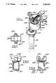
- FIG. 3is an elevation view of the primary winding and bobbin assembly in accordance with the present invention.
- FIG. 4is a view similar to FIG. 3 and rotated 90 to show further detail of the primary bobbin and winding assembly in accordance with the present invention
- FIG. 5is a plan view of the primary bobbin and winding assembly seen from the upper end thereof;
- FIG. 6is a plan view of the primary bobbin and winding assembly shown in FIGS. 3 and 4, as viewed from the bottom end thereof;
- FIG. 7is an elevation view of the secondary bobbin and winding assembly in accordance with the present invention.
- FIG. 8is a plan view of the secondary bobbin and winding assembly shown in FIG. 7 as viewed from the upper end thereof;
- FIG. 9is a plan view of the secondary bobbin and winding assembly shown in FIG. 7 as viewed from the bottom thereof;
- FIGS. 10 and 10bare an elevation view, shown partially in section, of the primary bobbin and winding assembly in combination with the T-bar steel laminated core in accordance with the present invention
- FIG. 11is an elevation view of the primary and secondary bobbin and winding assemblies in combination with the laminated core assembly components in accordance with the present invention.
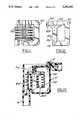
- FIG. 12is an elevation view showing only the assembly of the steel laminated C-shaped core, and T-shaped core, in combination with the permanent magnet in accordance with the present invention
- FIG. 13is an elevation view, shown in section, of the entire ignition coil assembly in accordance with the present invention, but excluding any showing of the lower boot member;
- FIGS. 14 and 14aare an elevation view shown partially in section of the housing, less the inner iron core and bobbin assemblies, and in combination with the lower boot member, in accordance with the present invention
- FIG. 15is a perspective view of the housing mounting member boss bushing which is injection molded into the housing mounting member arm and boss assembly in accordance with the present invention.
- FIG. 1the overall assembly of the ignition coil assembly of the present invention.
- the ignition coilis a coil-per-plug type ignition coil assembly mounted upon and electrically connected to a typical ignition spark plug as shown in phantom. It will be noted that the ignition coil assembly is extremely compact. It includes a generally annular housing 10 within which is nested a steel laminated C-shaped core member 100 which provides an open cavity portion or air gap between its terminal ends, and with a primary and secondary bobbin assembly 200, 400 residing within the cavity portion between the terminal ends of the C-shaped core member 100.
- the primary coil member 200includes a T-shaped steel laminated core member (not shown) extending axially through the primary bobbin.
- the primary bobbinincludes a pair of primary terminal receptacles 202, 204 within which are located solderless, spring-retained, insulation displacement terminals.
- a primary connector assembly 12is adapted to clip onto the housing and includes leads in a receptacle portion 14 which establishes electrical connection across the primary and secondary coils in a manner to be described below.
- the secondary bobbin 400includes an input terminal 402 and a corresponding secondary bobbin output terminal (not shown in FIG. 1) which is located at the lower end of the secondary bobbin within the area of the terminal stem portion 16 of the housing.
- Slip-fit over the terminal stem portion 16is a flexible rubber boot 18 having a collar 20 Which grips the stem portion 16 and a barrel portion 22 adapted to grip and establish electrical connection with a spark plug head in a manner described below.
- FIG. 2further illustrates the unique compactness of the ignition coil assembly, and the manner in which it is assembled in unique modular assembly form.
- the primary bobbin subassembly 200includes a primary bobbin 206 having a primary coil 208 wound around the longitudinal axis thereof.
- the bobbin 206includes an upper channel-shaped head portion 210 and a lower annular portion 212.
- the bobbinincludes a rectangularly shaped bore 228 extending along the longitudinal axis thereof from one end to the other and sized to receive, in sliding fit, the T-shaped steel laminated core member 300.
- the upper channel section of the bobbinincludes a pair of spaced side walls 214 and a stop wall 216 at one end thereof, extending between the side walls.
- the upper channel sectionincludes three locating lugs 218, 220, 222, (218 and 222 not shown in this view). Two of these (218, 220) are located at the bottom of the respective terminal receptacles 202, 204. At the bottom of the primary bobbin is located an annular collar 224 and radially projecting from the collar is a pair of similar locating lugs 226 axially aligned with those extending from the terminal portions 202, 204 of the upper portion of the bobbin.
- the T-shaped core member 300which is slidingly received within the primary bobbin assembly 200 includes a cross-bar member 308 having tapered under sides 302 at one end and a tapered end or ramp 304 at its other end.
- the T-shaped core memberis a series of steel laminations secured together by punched or stamped stakes 306.
- Magnetically attached to the cross-bar portion 308is a plate-like permanent magnet 310. It includes a plurality of protrusions 312 on its upper surface. The height or length of each equally or slightly exceeding the maximum differential in stack-up tolerances governing the filling of the distance between the terminal ends of the C-shaped core member by the T-shaped core member and permanent magnet.
- the magnet memberis made of a bonded magnetic material which is substantially less than fully dense. It is made of grains of rare earth, high energy materials such as neodymium and samarium evenly dispersed within a binder, such as a plastic or epoxy matrix. In our preferred example, noedymium grains are dispersed within a nylon matrix such that the resulting composite material has a flux density of 4.2 kilogauss, whereas a fully dense magnet would have a flux density of 12 kilogauss.
- the primary coil bobbin assembly 200is adapted to be received within the annular secondary coil bobbin assembly 400.
- the secondary coil bobbin assemblyincludes integral secondary terminal portions 402 and 404. Within the end of each terminal portion is located a similar solderless spring-retained insulation terminal. Located about the inner cylindrical surface of the secondary terminal are three longitudinally extending slots 406, 408, 410, each being open to the coil winding 412 which is wound about the outer periphery of the secondary coil bobbin member 400 and connected about its respective ends to input and output secondary terminal portions 402, 404.
- the width of the slots 406, 408, 410matches that of the locating lugs 218, 220, 222 respectively of the primary bobbin assembly.
- the primary bobbinwhen the primary bobbin is inserted within the secondary bobbin, it is uniquely located within the secondary bobbin by keying the circumferential location of each locating lug. Also, the relative longitudinal location is fixed by virtue of the tapered undersides of the upper channel portion of the bobbin coming to rest on the edge or lip of the secondary bobbin. Further, the slots 406, 410 on the secondary bobbin have tabs 418 on the underside of the bobbin. As the upper channel portion of the primary bobbin comes to rest on the lip of the secondary bobbin, the protrusions 232 on the locating lugs 226 engage the tabs 418, thus snapping the primary bobbin in place.
- the plastic terminal insulating clip member 102made of modified polypropylene with 10% filler, or other suitable material, is slid within the open cavity of the C-shaped core member 100.
- the clipis sized such that the side walls thereof firmly grip the outer walls of the C-shaped core member, as shown and described below.
- the C-shaped core member loop with clip 102is inserted from its open end within the channel-shaped shaped upper head portion of the primary bobbin such that the upper terminal end 104 of the C-shaped core member will come to rest against the stop wall 216 of the primary bobbin.
- the ramp or inclined end portion 304 of the T-shaped core member within the primary bobbin assemblywill engage in line-to-line contact along the corresponding ramp end portion 106 of the C-shaped core member at its other terminal end 108.
- the assemblycontinues until the T-shaped core member abuts the stop shoulder 110 of the C-shaped core member.
- the degree of lift designed into the inclined rampis also designed to force the T-shaped core member 300 and permanent magnet 310 into full contact with the other terminal end portion of the C-shaped core member 100, thus virtually eliminating any air gap which might otherwise exist between the C-shaped core member and the T-shaped core member.
- the core and primary and secondary bobbin sub-assemblyis slid within the housing 10. Thereafter, the boot assembly including the retainer spring 24 is slip-fit onto the one end of the housing and the primary connector assembly 12 is clipped onto the opposite end of the housing. This completes the core assembly, as shown in FIGS. 1 and 2.
- the primary coil bobbin 200is a conventional injection molded member made of nylon, or other suitable material, and includes a channel-shaped head portion 210 and lower annular reel portion 212 upon which is spirally wound a primary coil 208.
- the primary coil bobbin 200Through the center of the bobbin is a rectangular cross-sectioned bore 228 for receiving the T-shaped core member in sliding fit engagement.
- Upper locating lug 222is shown in FIG. 4 as well as the lower locating lugs 226 as shown in FIG. 6, which are located longitudinally opposite the respective upper locating lugs 218, 220.
- a pair of guide rails 230located on the bottom collar 224.
- the guide rails 230extend transversely over the portion of the rectangular bore 228 and are spaced from one another a distance slightly greater than the width of the C-shaped core member.
- the guide rails 230serve to receive the lower terminal portion 108 of the C-shaped core member 100 as it is being slipped into engagement with the primary and secondary bobbin assemblies.
- the primary bobbin assemblyis uniquely constructed such that the relative position of the bobbin member with the C-shaped core on the one hand and the secondary bobbin assembly on the other, can only be accomplished in one particular orientation. Misassembly is thereby eliminated.
- the T-shaped core memberis oriented such that the cross-bar member is received within the channel member 210, and that the head of the cross-bar member 308 comes to rest with the tapered side walls 302 in such a manner that the top of the head is just below the stop wall 216, and that the ramp 304 at the other end of the T-bar member 300 is inclined in a manner to correspondingly receive the ramp portion 106 of the C-shaped core and is fitted within the lower guide rails 230. It will also be noted from FIG.
- the plate-like permanent magnet member 310being of the same width and length as the top of the cross-bar member can be slid into place from the open side of the channel members whereupon it will come to rest at the stop wall 216. While it is preferred that the protrusions 312 on the permanent magnet be located so as to engage the C-shaped core member, the coil assembly would work equally well if the protrusions were facing the cross-bar member. Forming the protrusions on the interengaging surface of the core member 300 is also an alternative.
- the secondary coil bobbin 400is an integral injection molded plastic member, preferably made of nylon or similar material. It is generally cylindrical, with the inner diameter being sized to closely receive the primary bobbin assembly and including a plurality of elongated slots 406, 408, 410 extending completely through the side wall of the bobbin.
- the input and output terminal portions 402, 404are located at respective ends of the bobbin.
- the bobbinincludes a plurality of annular ribs 414 for maintaining the location of the coil as it is wound annularly over the bobbin.
- the slots 406, 408, 410are adapted to receive the locating lugs 218, 220, 222 respectively of the primary bobbin assembly as earlier explained. Further, after assembly of all components, when the ignition coil assembly is to be filled with the potting material pursuant to conventional practice, the potting material will flow within the elongated slots on the inner portion of the secondary bobbin assembly and radially through to all inner portions of the secondary winding, thus enhancing the efficient filling of the coil assembly and eliminating all voids within the components.
- FIG. 12there is shown just the assembly of the steel laminated core members 100, 300 and the permanent magnet 310.
- the C-shaped core member 100includes at one end portion a ramp 106 which terminates at a stop shoulder 110.
- the width of the rampis designed to match that of the T-shaped cross-member so that upon assembly the core members will be flush at the outer periphery.
- the permanent magnet 310is provided with a number of protrusions 312 which extend outwardly from the permanent magnet a distance equal to or slightly exceeding the maximum differential in stack up of dimensional tolerances of the components, i.e. the collective maximum difference between the minimum and maximum tolerances on each component.
- the protrusionsWhen the core members are assembled with the minimum stack-up tolerance differential, the protrusions will be completely flattened over the surface of the permanent magnet under the force of the T-bar member 300 being forced along the ramp portion 106.
- the maximum tolerance differentialexists thereby allowing what would otherwise be an air gap between the core members 100, 300, the protrusions 312 of the permanent magnet 310 will still come into contact with the C-shaped coil member and the air gap will be virtually eliminated or the air gap will be present only in the area of the greatest cross-sectional area of the T-bar core member 300, which is the cross-bar portion 308.
- FIG. 13shows a cross-section of the ignition coil assembly previously described. It will be noted that no air gap exists between the permanent magnet 310 and either core members 100, 300. It will be noticed that the primary coil bobbin member 200 is precisely and compactly located within the annular secondary coil bobbin member 400 and that the primary and secondary bobbin assemblies are closely nestled within the open portion of the C-shaped member 100. Further, it will be noted how the thermal insulating clip 102 insulates the secondary winding assembly precluding the possibility of thermal stress generated by the heat and resultant expansion of the C-shaped core member from causing any stress cracking which might otherwise cause a short circuit between the C-shaped core member and the secondary winding.
- FIG. 14illustrates another important feature of the subject invention, mainly the manner in which the rubber boot member 18 is adapted to be slip-fit onto the housing portion 16 and to loosely retain the retainer spring 24 by virtue of its being completely open at one end and concluding at its other end at an annular integral rubber inwardly directed lip 26 which acts as a spring arrest.
- the retaining springmay be slipped into the boot from the end opposite the spring arrest lip 26.
- the springis loose fit within the housing terminal portion 16 and a of sufficient non-compressed length to come into loose contact with the half-moon shaped base 28 of the secondary coil output terminal 404.
- the arrest lip 26is constructed with sufficient radial dimension such that the spring will be retained within the boot when the spark plug is detached from the boot assembly.
- a molded-in-place core receiving well 30having a pair of oppositely disposed side walls 32, one of which is shown, spaced from one another sufficiently to closely receive the lower portion of the C-shaped core member 100 and retain the coil member in fixed position relative to the housing.
- FIGS. 14 and 15show a uniquely constructed powdered metal sintered bushing 34 to be injection molded into the housing mounting member 36.
- the bushingincludes a plurality of helical retention ribs 38 spaced about the circumference of the bushing. Any tendency of the bushing 34 to turn in the housing is thereby precluded as well as any tendencies toward axial displacement.
Landscapes
- Engineering & Computer Science (AREA)
- Power Engineering (AREA)
- Chemical & Material Sciences (AREA)
- Combustion & Propulsion (AREA)
- Mechanical Engineering (AREA)
- General Engineering & Computer Science (AREA)
- Ignition Installations For Internal Combustion Engines (AREA)
Abstract
Description
Claims (23)
Priority Applications (9)
| Application Number | Priority Date | Filing Date | Title |
|---|---|---|---|
| US07/939,800US5241941A (en) | 1992-09-03 | 1992-09-03 | Ignition coil |
| US08/004,007US5285761A (en) | 1992-09-03 | 1993-01-15 | Ignition coil |
| US08/080,146US5335642A (en) | 1992-09-03 | 1993-06-23 | Ignition coil |
| ES94908865TES2114182T3 (en) | 1992-09-03 | 1993-08-31 | IGNITION COIL. |
| DE69317894TDE69317894T2 (en) | 1992-09-03 | 1993-08-31 | IGNITION COIL |
| EP94908865AEP0658270B1 (en) | 1992-09-03 | 1993-08-31 | Ignition coil |
| PCT/GB1993/001841WO1994006134A2 (en) | 1992-09-03 | 1993-08-31 | Ignition coil |
| HU9500649AHU216854B (en) | 1992-09-03 | 1993-08-31 | Ignition coil |
| CN93116575ACN1043070C (en) | 1992-09-03 | 1993-09-01 | Ignition coil assembly and method of manufacture thereof |
Applications Claiming Priority (1)
| Application Number | Priority Date | Filing Date | Title |
|---|---|---|---|
| US07/939,800US5241941A (en) | 1992-09-03 | 1992-09-03 | Ignition coil |
Related Child Applications (2)
| Application Number | Title | Priority Date | Filing Date |
|---|---|---|---|
| US08/004,007Continuation-In-PartUS5285761A (en) | 1992-09-03 | 1993-01-15 | Ignition coil |
| US08/080,146Continuation-In-PartUS5335642A (en) | 1992-09-03 | 1993-06-23 | Ignition coil |
Publications (1)
| Publication Number | Publication Date |
|---|---|
| US5241941Atrue US5241941A (en) | 1993-09-07 |
Family
ID=25473754
Family Applications (1)
| Application Number | Title | Priority Date | Filing Date |
|---|---|---|---|
| US07/939,800Expired - LifetimeUS5241941A (en) | 1992-09-03 | 1992-09-03 | Ignition coil |
Country Status (7)
| Country | Link |
|---|---|
| US (1) | US5241941A (en) |
| EP (1) | EP0658270B1 (en) |
| CN (1) | CN1043070C (en) |
| DE (1) | DE69317894T2 (en) |
| ES (1) | ES2114182T3 (en) |
| HU (1) | HU216854B (en) |
| WO (1) | WO1994006134A2 (en) |
Cited By (18)
| Publication number | Priority date | Publication date | Assignee | Title |
|---|---|---|---|---|
| WO1994016454A1 (en)* | 1993-01-15 | 1994-07-21 | Ford Motor Company | Ignition coil |
| US5333592A (en)* | 1991-11-05 | 1994-08-02 | Robert Bosch Gmbh | Ignition coil for ignition systems in combustion engines |
| US5359982A (en)* | 1992-08-13 | 1994-11-01 | Mitsubishi Denki Kabushiki Kaisha | Ignitor for an internal combustion engine |
| US5406242A (en)* | 1994-01-10 | 1995-04-11 | Ford Motor Company | Ignition coil |
| US5497756A (en)* | 1994-02-17 | 1996-03-12 | Robert Bosch Gmbh | Ignition coil for an internal combustion engine |
| US5523142A (en)* | 1991-04-25 | 1996-06-04 | Sagem Allumage | Metal fixation insert for a plastic part and part including such an insert |
| US5594616A (en)* | 1995-03-27 | 1997-01-14 | Ford Motor Company | Electrical component connecting provisions for an ignition coil |
| US5632259A (en)* | 1995-04-21 | 1997-05-27 | Hitachi, Ltd. | Ignition apparatus for an internal combustion engine |
| GB2328324A (en)* | 1997-06-09 | 1999-02-17 | Ford Global Tech Inc | Ignition coil assembly with means for suppressing high frequency signals |
| FR2819623A1 (en)* | 2001-01-17 | 2002-07-19 | Sagem | Internal combustion engine ignition coil having end section with permanent magnet with permanent axis perpendicular magnet with permanent axis centre and having flux return section. |
| US6427673B2 (en)* | 2000-02-04 | 2002-08-06 | Visteon Global Technologies, Inc. | Ignition coil assembly |
| US20090194084A1 (en)* | 2007-04-27 | 2009-08-06 | Denso Corporation | Ignition coil |
| US20090199827A1 (en)* | 2008-02-08 | 2009-08-13 | Skinner Albert A | Flux director for ignition coil assembly |
| JP2014060156A (en)* | 2012-09-14 | 2014-04-03 | Tempel Steel Company | Automotive ignition coil having core with at least one embedded permanent magnet |
| US20160055962A1 (en)* | 2012-10-17 | 2016-02-25 | Denso Corporation | Ignition coil for internal combustion engine |
| JP2017034002A (en)* | 2015-07-29 | 2017-02-09 | 株式会社タムラ製作所 | Inductor |
| JP2017034001A (en)* | 2015-07-29 | 2017-02-09 | 株式会社タムラ製作所 | Inductor |
| US11342111B2 (en) | 2016-07-21 | 2022-05-24 | Denso Corporation | Ignition coil for internal combustion engine and manufacturing method thereof |
Families Citing this family (6)
| Publication number | Priority date | Publication date | Assignee | Title |
|---|---|---|---|---|
| US5335642A (en)* | 1992-09-03 | 1994-08-09 | Ford Motor Company | Ignition coil |
| WO1995006319A1 (en)* | 1993-08-26 | 1995-03-02 | Ford Motor Company Limited | Ignition coil assembly |
| JP3602267B2 (en)* | 1996-07-12 | 2004-12-15 | 本田技研工業株式会社 | Ignition coil device |
| FR2951579B1 (en)* | 2009-10-15 | 2017-08-11 | Valeo Systemes De Controle Moteur | CLOSED MAGNETIC CORE IGNITION COIL AND PERMANENT MAGNET AND METHOD FOR MANUFACTURING THE COIL |
| DE102010038004B4 (en)* | 2010-10-06 | 2014-10-02 | Prüfrex engineering e motion gmbh & co. kg | Spark generator and method for its production |
| GB201207039D0 (en) | 2012-04-23 | 2012-06-06 | British American Tobacco Co | Heating smokeable material |
Citations (16)
| Publication number | Priority date | Publication date | Assignee | Title |
|---|---|---|---|---|
| US3209295A (en)* | 1959-03-13 | 1965-09-28 | Baermann Max | Ignition coil with permanent magnets in core |
| US4546753A (en)* | 1982-08-11 | 1985-10-15 | Ducellier & Cie | Ignition coil for internal combustion engines |
| US4834056A (en)* | 1985-04-17 | 1989-05-30 | Nippondenso Co., Ltd. | Ignition coil unit for internal combustion engines |
| US4841944A (en)* | 1987-06-30 | 1989-06-27 | Tsutomu Maeda | Ingition system |
| US4893105A (en)* | 1987-06-30 | 1990-01-09 | Tdk Corporation | Transformer with tapered core |
| US4903674A (en)* | 1989-03-13 | 1990-02-27 | General Motors Corporation | Spark developing apparatus for internal combustion engines |
| US4990881A (en)* | 1988-07-28 | 1991-02-05 | Nippondenso Co., Ltd. | Ignition coil with permanent magnet |
| US5036827A (en)* | 1988-04-26 | 1991-08-06 | Hitachi, Ltd. | Ignition coil-incorporated distributor for internal combustion engines |
| US5038745A (en)* | 1987-08-18 | 1991-08-13 | Bayerische Motoren Werke Ag | Ignition unit for internal combustion engines |
| US5101803A (en)* | 1989-11-10 | 1992-04-07 | Nippondenso Co., Ltd. | Ignition coil |
| US5144935A (en)* | 1990-10-03 | 1992-09-08 | Mitsubishi Denki Kabushiki Kaisha | Ignition coil unit for an internal combustion engine |
| US5146906A (en)* | 1990-10-05 | 1992-09-15 | Honda Giken Kogyo Kabushiki Kaisha | Ignition system for internal combustion engine |
| US5170768A (en)* | 1991-12-23 | 1992-12-15 | Ford Motor Company | Modular twin tower distributorless ignition coil |
| US5170767A (en)* | 1990-03-08 | 1992-12-15 | Nippondenso Co., Ltd. | Ignition coil for internal combustion engine |
| US5186154A (en)* | 1990-05-15 | 1993-02-16 | Mitsubishi Denki K.K. | Ignition coil device for an internal combustion engine |
| US5191872A (en)* | 1991-04-30 | 1993-03-09 | Mitsubishi Denki Kabushiki Kaisha | Ignition coil unit for an internal combustion engine |
Family Cites Families (7)
| Publication number | Priority date | Publication date | Assignee | Title |
|---|---|---|---|---|
| DE3318370C2 (en)* | 1983-05-20 | 1986-02-06 | Waasner, Bruno, 8550 Forchheim | Sheet metal core made of two parts and with three legs |
| DE3323958A1 (en)* | 1983-07-02 | 1985-01-10 | Friemann & Wolf Gerätebau GmbH, 4100 Duisburg | Transformer having an iron core which is composed of sheet-metal laminates |
| JPS63160211A (en)* | 1986-12-23 | 1988-07-04 | Matsushita Electric Works Ltd | Permanent magnet |
| US5015982A (en)* | 1989-08-10 | 1991-05-14 | General Motors Corporation | Ignition coil |
| CA2012485A1 (en)* | 1989-08-10 | 1991-02-10 | Jack R. Phillips | Ignition coil |
| JPH03136219A (en)* | 1989-10-20 | 1991-06-11 | Aisan Ind Co Ltd | Ignition coil for internal combustion engine |
| CN2099200U (en)* | 1991-06-12 | 1992-03-18 | 张媛 | Spark coil for petrol engine |
- 1992
- 1992-09-03USUS07/939,800patent/US5241941A/ennot_activeExpired - Lifetime
- 1993
- 1993-08-31EPEP94908865Apatent/EP0658270B1/ennot_activeExpired - Lifetime
- 1993-08-31DEDE69317894Tpatent/DE69317894T2/ennot_activeExpired - Lifetime
- 1993-08-31WOPCT/GB1993/001841patent/WO1994006134A2/enactiveIP Right Grant
- 1993-08-31HUHU9500649Apatent/HU216854B/ennot_activeIP Right Cessation
- 1993-08-31ESES94908865Tpatent/ES2114182T3/ennot_activeExpired - Lifetime
- 1993-09-01CNCN93116575Apatent/CN1043070C/ennot_activeExpired - Fee Related
Patent Citations (16)
| Publication number | Priority date | Publication date | Assignee | Title |
|---|---|---|---|---|
| US3209295A (en)* | 1959-03-13 | 1965-09-28 | Baermann Max | Ignition coil with permanent magnets in core |
| US4546753A (en)* | 1982-08-11 | 1985-10-15 | Ducellier & Cie | Ignition coil for internal combustion engines |
| US4834056A (en)* | 1985-04-17 | 1989-05-30 | Nippondenso Co., Ltd. | Ignition coil unit for internal combustion engines |
| US4841944A (en)* | 1987-06-30 | 1989-06-27 | Tsutomu Maeda | Ingition system |
| US4893105A (en)* | 1987-06-30 | 1990-01-09 | Tdk Corporation | Transformer with tapered core |
| US5038745A (en)* | 1987-08-18 | 1991-08-13 | Bayerische Motoren Werke Ag | Ignition unit for internal combustion engines |
| US5036827A (en)* | 1988-04-26 | 1991-08-06 | Hitachi, Ltd. | Ignition coil-incorporated distributor for internal combustion engines |
| US4990881A (en)* | 1988-07-28 | 1991-02-05 | Nippondenso Co., Ltd. | Ignition coil with permanent magnet |
| US4903674A (en)* | 1989-03-13 | 1990-02-27 | General Motors Corporation | Spark developing apparatus for internal combustion engines |
| US5101803A (en)* | 1989-11-10 | 1992-04-07 | Nippondenso Co., Ltd. | Ignition coil |
| US5170767A (en)* | 1990-03-08 | 1992-12-15 | Nippondenso Co., Ltd. | Ignition coil for internal combustion engine |
| US5186154A (en)* | 1990-05-15 | 1993-02-16 | Mitsubishi Denki K.K. | Ignition coil device for an internal combustion engine |
| US5144935A (en)* | 1990-10-03 | 1992-09-08 | Mitsubishi Denki Kabushiki Kaisha | Ignition coil unit for an internal combustion engine |
| US5146906A (en)* | 1990-10-05 | 1992-09-15 | Honda Giken Kogyo Kabushiki Kaisha | Ignition system for internal combustion engine |
| US5191872A (en)* | 1991-04-30 | 1993-03-09 | Mitsubishi Denki Kabushiki Kaisha | Ignition coil unit for an internal combustion engine |
| US5170768A (en)* | 1991-12-23 | 1992-12-15 | Ford Motor Company | Modular twin tower distributorless ignition coil |
Cited By (23)
| Publication number | Priority date | Publication date | Assignee | Title |
|---|---|---|---|---|
| US5523142A (en)* | 1991-04-25 | 1996-06-04 | Sagem Allumage | Metal fixation insert for a plastic part and part including such an insert |
| US5333592A (en)* | 1991-11-05 | 1994-08-02 | Robert Bosch Gmbh | Ignition coil for ignition systems in combustion engines |
| US5359982A (en)* | 1992-08-13 | 1994-11-01 | Mitsubishi Denki Kabushiki Kaisha | Ignitor for an internal combustion engine |
| WO1994016454A1 (en)* | 1993-01-15 | 1994-07-21 | Ford Motor Company | Ignition coil |
| US5406242A (en)* | 1994-01-10 | 1995-04-11 | Ford Motor Company | Ignition coil |
| US5497756A (en)* | 1994-02-17 | 1996-03-12 | Robert Bosch Gmbh | Ignition coil for an internal combustion engine |
| US5594616A (en)* | 1995-03-27 | 1997-01-14 | Ford Motor Company | Electrical component connecting provisions for an ignition coil |
| US5632259A (en)* | 1995-04-21 | 1997-05-27 | Hitachi, Ltd. | Ignition apparatus for an internal combustion engine |
| GB2328324A (en)* | 1997-06-09 | 1999-02-17 | Ford Global Tech Inc | Ignition coil assembly with means for suppressing high frequency signals |
| GB2328324B (en)* | 1997-06-09 | 2001-10-17 | Ford Global Tech Inc | Ignition coil assembly |
| US6427673B2 (en)* | 2000-02-04 | 2002-08-06 | Visteon Global Technologies, Inc. | Ignition coil assembly |
| FR2819623A1 (en)* | 2001-01-17 | 2002-07-19 | Sagem | Internal combustion engine ignition coil having end section with permanent magnet with permanent axis perpendicular magnet with permanent axis centre and having flux return section. |
| US20090194084A1 (en)* | 2007-04-27 | 2009-08-06 | Denso Corporation | Ignition coil |
| US7849843B2 (en)* | 2007-04-27 | 2010-12-14 | Denso Corporation | Ignition coil |
| US20090199827A1 (en)* | 2008-02-08 | 2009-08-13 | Skinner Albert A | Flux director for ignition coil assembly |
| JP2014060156A (en)* | 2012-09-14 | 2014-04-03 | Tempel Steel Company | Automotive ignition coil having core with at least one embedded permanent magnet |
| US8854169B2 (en) | 2012-09-14 | 2014-10-07 | Tempel Steel Company | Automotive ignition coil having a core with at least one embedded permanent magnet |
| US20140334061A1 (en)* | 2012-09-14 | 2014-11-13 | Tempel Steel Company | Automotive ignition coil having a core with at least one embedded permanent magnet |
| US20160055962A1 (en)* | 2012-10-17 | 2016-02-25 | Denso Corporation | Ignition coil for internal combustion engine |
| US9728322B2 (en)* | 2012-10-17 | 2017-08-08 | Denso Corporation | Ignition coil for internal combustion engine |
| JP2017034002A (en)* | 2015-07-29 | 2017-02-09 | 株式会社タムラ製作所 | Inductor |
| JP2017034001A (en)* | 2015-07-29 | 2017-02-09 | 株式会社タムラ製作所 | Inductor |
| US11342111B2 (en) | 2016-07-21 | 2022-05-24 | Denso Corporation | Ignition coil for internal combustion engine and manufacturing method thereof |
Also Published As
| Publication number | Publication date |
|---|---|
| WO1994006134A2 (en) | 1994-03-17 |
| EP0658270B1 (en) | 1998-04-08 |
| EP0658270A1 (en) | 1995-06-21 |
| DE69317894D1 (en) | 1998-05-14 |
| HUT70771A (en) | 1995-11-28 |
| DE69317894T2 (en) | 1998-07-30 |
| HU9500649D0 (en) | 1995-04-28 |
| ES2114182T3 (en) | 1998-05-16 |
| CN1043070C (en) | 1999-04-21 |
| WO1994006134A3 (en) | 1994-04-14 |
| CN1084251A (en) | 1994-03-23 |
| HU216854B (en) | 1999-09-28 |
Similar Documents
| Publication | Publication Date | Title |
|---|---|---|
| US5241941A (en) | Ignition coil | |
| US5335642A (en) | Ignition coil | |
| US5685065A (en) | Method of making an ignition coil | |
| CN1020783C (en) | Ignition coil | |
| EP0431322A1 (en) | Ignition coil | |
| US5285761A (en) | Ignition coil | |
| EP0715764B1 (en) | Method of forming an ignition coil assembly | |
| US5703556A (en) | Ignition coil for an internal combustion engine | |
| EP0508374B1 (en) | Ignition coil unit for internal combustion engine | |
| JPH0715853B2 (en) | Energy storage type ignition coil | |
| US6188304B1 (en) | Ignition coil with microencapsulated magnets | |
| US5714922A (en) | Ignition coil for an internal combustion engine | |
| EP0785605A1 (en) | Engine igniting coil device | |
| US4509033A (en) | Ignition coil construction for engine ignition system | |
| JPH01316915A (en) | Ignition coil of automotive internal combustion engine and its manufacture | |
| EP0318613B1 (en) | High-voltage transformer and method for making same | |
| JP3192170B2 (en) | Ignition coil for internal combustion engine | |
| JP3631707B2 (en) | Ignition coil for internal combustion engine | |
| EP0638971A1 (en) | Ignition coil with reduced transverse size | |
| JP3200796B2 (en) | Ignition coil for internal combustion engine | |
| JP2936239B2 (en) | Ignition coil for internal combustion engine | |
| JP2769729B2 (en) | Ignition coil for internal combustion engine | |
| US20090199827A1 (en) | Flux director for ignition coil assembly | |
| JPH04106575U (en) | solenoid | |
| JPH05172028A (en) | Ignition coil for internal combustion engine |
Legal Events
| Date | Code | Title | Description |
|---|---|---|---|
| AS | Assignment | Owner name:FORD MOTOR COMPANY, MICHIGAN Free format text:ASSIGNMENT OF ASSIGNORS INTEREST.;ASSIGNORS:HANCOCK, ROBERT L.;PRITZ, STEVEN E.;BAUMAN, ROBERT C.;REEL/FRAME:006276/0610 Effective date:19920902 | |
| AS | Assignment | Owner name:FORD MOTOR COMPANY, MICHIGAN Free format text:ASSIGNMENT OF ASSIGNORS INTEREST;ASSIGNOR:NOWLAN, SHAWN JOSEPH;REEL/FRAME:006576/0328 Effective date:19930610 | |
| STCF | Information on status: patent grant | Free format text:PATENTED CASE | |
| FPAY | Fee payment | Year of fee payment:4 | |
| AS | Assignment | Owner name:VISTEON GLOBAL TECHNOLOGIES, INC., MICHIGAN Free format text:ASSIGNMENT OF ASSIGNORS INTEREST;ASSIGNOR:FORD MOTOR COMPANY;REEL/FRAME:010968/0220 Effective date:20000615 | |
| FPAY | Fee payment | Year of fee payment:8 | |
| FPAY | Fee payment | Year of fee payment:12 | |
| AS | Assignment | Owner name:AUTOMOTIVE COMPONENTS HOLDINGS, LLC, MICHIGAN Free format text:ASSIGNMENT OF ASSIGNORS INTEREST;ASSIGNOR:VISTEON GLOBAL TECHNOLOGIES, INC.;REEL/FRAME:016835/0448 Effective date:20051129 | |
| AS | Assignment | Owner name:FORD MOTOR COMPANY, MICHIGAN Free format text:ASSIGNMENT OF ASSIGNORS INTEREST;ASSIGNOR:AUTOMOTIVE COMPONENTS HOLDINGS, LLC;REEL/FRAME:017164/0694 Effective date:20060214 | |
| AS | Assignment | Owner name:FORD GLOBAL TECHNOLOGIES, LLC, MICHIGAN Free format text:ASSIGNMENT OF ASSIGNORS INTEREST;ASSIGNOR:FORD MOTOR COMPANY;REEL/FRAME:022562/0494 Effective date:20090414 Owner name:FORD GLOBAL TECHNOLOGIES, LLC,MICHIGAN Free format text:ASSIGNMENT OF ASSIGNORS INTEREST;ASSIGNOR:FORD MOTOR COMPANY;REEL/FRAME:022562/0494 Effective date:20090414 |