US5241936A - Foot pedal arrangement for electronic throttle control of truck engines - Google Patents
Foot pedal arrangement for electronic throttle control of truck enginesDownload PDFInfo
- Publication number
- US5241936A US5241936AUS07/756,430US75643091AUS5241936AUS 5241936 AUS5241936 AUS 5241936AUS 75643091 AUS75643091 AUS 75643091AUS 5241936 AUS5241936 AUS 5241936A
- Authority
- US
- United States
- Prior art keywords
- range
- foot pedal
- throttle
- support structure
- pedal
- Prior art date
- Legal status (The legal status is an assumption and is not a legal conclusion. Google has not performed a legal analysis and makes no representation as to the accuracy of the status listed.)
- Expired - Lifetime
Links
Images

Classifications
- G—PHYSICS
- G05—CONTROLLING; REGULATING
- G05G—CONTROL DEVICES OR SYSTEMS INSOFAR AS CHARACTERISED BY MECHANICAL FEATURES ONLY
- G05G1/00—Controlling members, e.g. knobs or handles; Assemblies or arrangements thereof; Indicating position of controlling members
- G05G1/30—Controlling members actuated by foot
- G05G1/38—Controlling members actuated by foot comprising means to continuously detect pedal position
- B—PERFORMING OPERATIONS; TRANSPORTING
- B60—VEHICLES IN GENERAL
- B60K—ARRANGEMENT OR MOUNTING OF PROPULSION UNITS OR OF TRANSMISSIONS IN VEHICLES; ARRANGEMENT OR MOUNTING OF PLURAL DIVERSE PRIME-MOVERS IN VEHICLES; AUXILIARY DRIVES FOR VEHICLES; INSTRUMENTATION OR DASHBOARDS FOR VEHICLES; ARRANGEMENTS IN CONNECTION WITH COOLING, AIR INTAKE, GAS EXHAUST OR FUEL SUPPLY OF PROPULSION UNITS IN VEHICLES
- B60K26/00—Arrangement or mounting of propulsion-unit control devices in vehicles
- B60K26/02—Arrangement or mounting of propulsion-unit control devices in vehicles of initiating means or elements
- F—MECHANICAL ENGINEERING; LIGHTING; HEATING; WEAPONS; BLASTING
- F05—INDEXING SCHEMES RELATING TO ENGINES OR PUMPS IN VARIOUS SUBCLASSES OF CLASSES F01-F04
- F05C—INDEXING SCHEME RELATING TO MATERIALS, MATERIAL PROPERTIES OR MATERIAL CHARACTERISTICS FOR MACHINES, ENGINES OR PUMPS OTHER THAN NON-POSITIVE-DISPLACEMENT MACHINES OR ENGINES
- F05C2201/00—Metals
- F05C2201/02—Light metals
- F05C2201/021—Aluminium
- Y—GENERAL TAGGING OF NEW TECHNOLOGICAL DEVELOPMENTS; GENERAL TAGGING OF CROSS-SECTIONAL TECHNOLOGIES SPANNING OVER SEVERAL SECTIONS OF THE IPC; TECHNICAL SUBJECTS COVERED BY FORMER USPC CROSS-REFERENCE ART COLLECTIONS [XRACs] AND DIGESTS
- Y10—TECHNICAL SUBJECTS COVERED BY FORMER USPC
- Y10T—TECHNICAL SUBJECTS COVERED BY FORMER US CLASSIFICATION
- Y10T74/00—Machine element or mechanism
- Y10T74/20—Control lever and linkage systems
- Y10T74/20528—Foot operated
- Y10T74/20534—Accelerator
Definitions
- This inventionrelates generally to controls, and more particularly to a foot pedal control coupled to a fuel dispensing system of an internal-combustion engine.
- Actuation of a foot pedal coupled to a fuel dispensing system of an enginealters the output of fuel discharged by the fuel dispensing system.
- the unactuated foot pedalis held in a home or idle position by a spring arrangement, and the operator, by depressing the pedal causes an increase of the fuel output from the fuel dispensing system, thereby increasing engine RPM and/or power output of the engine.
- An important feature of diesel engines as well as many spark-ignition enginesis the fuel-injection system, consisting of pumps that meter and place the fuel under injection pressure, the injection nozzles and the governing controls. Controlling the rate of fuel dispensed to the cylinders of an internal combustion engine, commonly referred to as throttle control, is accomplished in a fuel-injection system by adjusting the output of a fuel pump or a system of fuel pumps that supply the cylinders.
- Fuel controlshave evolved from mechanical linkages coupling a foot pedal to a control rack of a fuel pump system, to an electronic linkage coupling the foot pedal to a computer, the computer monitoring, inter alia, a sensor that detects incremental movement of the foot pedal, and responsive to such detected movement and other input data, controlling the output of the fuel pump system.
- a fuel pump systemis suitably operated by one or more servomechanisms responsive to control signals from a computer, which monitors an input signal provided by a sensor coupled to the foot pedal.
- the foot-pedal sensorsuitably a potentiometer, is actuated in response to depression of the foot pedal by the operator of the vehicle.
- the computerthus controls fuel flow to the engine, generating appropriate control signals in response to monitored input signals from the foot-pedal potentiometer as well as other input signals from sensors which detect both internal and external engine operating parameters such as temperature, humidity, barometric pressure, engine RPM and load, etc., providing increased engine efficiency, fuel economy and reduced emission of pollutants to the atmosphere.
- 4,958,607which is assigned to the same assignee as the instant invention, provides a suspended pedal configuration, which is a desirable arrangement; however, many of the mechanical elements are disposed exteriorly on the support structure, and the pivot of the foot pedal is spaced apart from the front wall farther than desirable in the limited space of the truck cab. Particularly, the foot-pedal pivot is situated relatively far from the front wall of truck cab, well beyond the pivot of the potentiometer actuating mechanism. It is desirable to locate the pivot point of the foot pedal as close to the front wall as possible in order to conserve space in the often cramped confines of a truck cab.
- a more specific object of the present inventionis to provide a foot pedal arrangement with improved pedal pressure differential.
- Another object of the instant inventionis to provide an improved foot pedal arrangement which locates the pivot of the foot pedal close to the front wall of the truck cab.
- Another object of the inventionis to provide an improved compact foot pedal arrangement with an aesthetically pleasing, uncluttered appearance, and having fewer moving components virtually all of which are internally disposed for safer operation and for protection from dirt and contaminants.
- the present inventionutilizes a sensor to generate a signal representative of foot-pedal depression, which is monitored by a computer.
- the unique arrangement of the components and the means for translating rotary motion of the foot pedal to the input of the sensorallows mounting the pedal closer to the front wall of the truck cab than wa possible in previous arrangements.
- a support structureprovides a housing in which the pivot of a suspended foot pedal is journaled, and on which a sensor is mounted.
- the housing, and a pivotally mounted cylindrical drum of the foot pedal conjoined with the housing,provide an enclosure containing a spring which applies rotative resistant bias to the foot pedal, and interconnecting elements which translate pedal movement into sensor input.
- An internal gear defined on the annular rim of the foot-pedal drummeshes with a pinion having an axial shaft journaled in the housing, the shaft providing input to the sensor, thereby translating foot-pedal movement into sensor output.
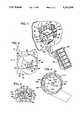
- FIG. 1is a perspective view of a foot pedal arrangement in accordance with the present invention
- FIG. 2is a side view of the support structure of the foot pedal arrangement in accordance with the invention.
- FIG. 3is a plan view of the pinion bearing/lever stop element of the foot pedal arrangement
- FIG. 4is a section view, taken near its open end, of the foot-pedal drum according to the present invention.
- FIG. 5is an exploded perspective view, partially cut away, illustrating the various components of the foot pedal arrangement of FIGS. 1 through 4.
- a foot pedal assembly 10incorporates a support structure 4, which is suitably machined or die cast from aluminum, and which includes a base plate 6 configured to be mounted and rigidly attached to a front wall 8 of a cab of a diesel engine powered truck, e.g., by bolts 2 (shown in dash line).
- the features and configuration of the support structure 4, described in detail below,provide support for a foot-pedal assembly 10, a potentiometer 12 and internal interconnecting elements that translate foot-pedal movement into rotational movement of the potentiometer shaft.
- Top wall 16 and side wall 18 elements of the support structure 4extend outwardly from the base plate 6, and with the base plate 6 define a housing 20 open on one side and having a formed recess 22 with a cylindriform interior surface 24.
- a cylindrical boss 26 and a cylindrical sleeve 28 having a common axis 30 with the boss 26extend into the recess 22 from the closed side wall 18.
- a longitudinal groove 32 defined in the periphery of the sleeve 28extends the length thereof, and a common central bore 34 extends through the sleeve 28, the boss 26 and the side wall 18.
- a needle bearing 36is pressed into the bore 34 at the distal end of the sleeve 28, while a second needle bearing 38 is pressed into the opposite end of the bore 34 from the side wall 18.
- a pinion bearing/lever stop element 40is adapted to be fastened to the side wall 1 of the housing 20 and provides a mounting means for the potentiometer 12 exteriorly of the housing 20, a seat inside the housing 20 for a pinion 44, and interconnection between the pinion 44 and potentiometer 12, later described.
- the pinion bearing/lever stop element 40comprises a mounting pad 46 adapted for attachment outside the side wall 18 of the housing 20, the pad 46 being positioned with respect to the side wall 18 by an irregularly shaped locating boss or dowel 48 extending from the pad 46 into an aperture 50 machined or die cast in the side wall 18, the boss 48 having essentially the same thickness as the side wall 18 and being received closely in the aperture 50, which has essentially the same shape as the boss 48 such that the boss forms a closure of the side wall aperture 50.
- a configured pillow block 52Extending into the housing 20 from the boss 48 and integral with the element 40, a configured pillow block 52 provides a seat for the pinion 44 in a generally cylindriform recess 54 defined in the block 52.
- the recess 54is defined by a platform or base 55 and upwardly extending ears 56, 57 interiorly contoured in cylindrical form commensurate with the shape of the pinion 44. Top surfaces of the ears 56, 57 define an arc (designated in FIG. 3 by dashed line 58) concentric with the axis 30.
- a bore 60laterally intersects the base 55 and extends through the boss 48 and pad 46.
- a counterbore 61defined exteriorly in the pad 46 coaxially with the bore 60 receives cylindrical protrusion 62 of the potentiometer 12, the potentiometer being attached to the side wall 18 by suitable fasteners 64 extending through apertures 66 in the pad 46.
- the pinion 44which seats rotatably inside the recess 54, is formed with peripheral gear teeth 68, six in the presently described embodiment of the invention, that subtend an angle of approximately 135 degrees about an axis 74 of the pinion; an axial shaft 76 of the pinion 44 extends through the bore 60 and engages an input shaft 78 of the potentiometer 12.
- the pinion 44is suitably formed from a rigid polymeric material such as glass reinforced nylon.
- the configuration of the recess 54allows a rotational throw of about 55 degrees of the pinion 44 seated therein.
- the pinion gear teeth 68as they rotate through a position normal to the platform 55, project below the arc 58.
- Bearing surfaces 70, 72 defined at either end of the configured block 52 beneath the ears 56, 57provide lever stops which limit rotational movement of the foot pedal as described hereinafter.
- the foot-pedal assembly 10includes a drive lever 84 extending from and affixed at its proximal end to a configured drum 86, which is in the shape of cylinder normal to the drive lever 84 and open at one end to a cavity 88.
- a hub 90 formed at the closed end 91 of the drum 86is eccentric with respect to the cylindrical periphery of the hub.
- the drive lever 84 and drum 86are suitably formed as a unitary element from a rigid polymeric material such as glass reinforced nylon.
- a conventional pedal 92is pivotally attached to the drive lever 84 by a pin 94 extending through an aperture 96 in the lever 84 and a clevis 98 on the underside of the pedal.
- a spring 100urges the pedal against an angled landing 102 on the lever 84.
- a pivot 104which is affixed to the hub 90 as by pressing into an aperture 106, projects into the cavity 88 such that when the drum 86 is inserted into the formed recess 22 of the housing 20 the pivot 104 slides into the central bore 34 and is journaled in the needle bearings 36, 38, thus providing pivotal motion of the pedal drive lever 84 and drum 86 about the pivot 104 and the axis 30.
- the pivot 104is axially retained in the housing 20 by a snap ring 108.
- the drum 86 and housing 20conjoined form an enclosure, the drum 86 and the housing 20 each closing the other, which encloses and protect the internal interconnecting elements that translate rotative foot-pedal movement into rotational movement of the potentiometer shaft 78.
- the periphery of the drum 86is circular and conforms generally with the cylindriform interior surface 24 of the housing 20, the drum rotates eccentrically with respect to the surface 24 because of the eccentricity of the axis 30 with respect to the periphery of the drum 86.
- the cavity 88defined by internally projecting nubs 110, 110' of cylindrical wall 112 of the drum 86 and the internal surface of a lobe 114 is configured concentrically (as indicated in FIG. 4 by dashed line 115) with the pivot 104 about the axis 30, so as to loosely and slidably envelop the boss 26 of the support structure 4, when the drum 86 and housing 20 are conjoined.
- Rotation of the drum 8 about the pivotis limited by engagement of radial limit stops 120, 122, respectively, against bearing surfaces 70, 72 of the pillow block 52.
- the lobe 114defines a slot 124 Open to the cavity 88 of the drum 86.
- the slot 124extends substantially the depth of the drum beyond the radial limit stop 120 and is configured to receive external catches 126 of a pair of coil springs 12 disposed inside the cavity 88 of the drum 86 when the foot-pedal assembly and the support structure 4 are conjoined.
- Washers 130separate the springs from each other and from the face of the pillow block 52.
- Internal catches 132 of the springs 128are inserted into the longitudinal groove 32 of the sleeve 28.
- the springs 128 installed under tensionapply torque to the drum 86 in a counterclockwise direction with reference to FIG. 4, the rotation of the drum 86 being checked by engagement of the limit stop 122 against bearing surface 72 of the pillow block 52; in such position of the drum 86, the foot pedal, under spring pressure or bias, is said to be in a home or idle position.
- the pinion 44as shown in FIG. 3
- the potentiometer shaftwhich is coupled by way of the rack-and-pinion gearing arrangement to the foot pedal, are in the home position.
- the foot pedal 92is depressed moving the foot pedal from the home position, pivoting the drum 86 about the axis 30, clockwise with reference to FIG. 4.
- the rack 116rotates clockwise through a predetermined arc
- the pinion 44rotates, the shaft of which in turn rotates the potentiometer 12.
- Rotation of the drum 86continues as the foot pedal is further depressed until the radial limit stop 120 engages the lever stop 70 of the pillow block 52.
- a computer 134 coupled to the potentiometer 12 by a bus 136periodically monitors the output signal of the potentiometer, detecting incremental movement of the foot pedal, and generates appropriate control signals for controlling fuel flow to the engine, based in part on foot-pedal position.
- the degree of rotation between the limit stops 120, 122is determined by the rotational specifications of the potentiometer in ranging from minimum to maximum output signal value.
- the potentiometerrotates 53 degrees, while the foot-pedal drive lever pivots approximately 20 degrees.
- the torque springs 128act directly on the foot-pedal drum applying resistant force to the element having the lesser degree of rotation, the force differential between home position or idle and full throttle being therefore substantially reduced to approximately 10 pounds.
- the foot pedal arrangementcan be reconfigured to provide for sensors having different rotational requirements, or to provide greater or lesser rotational movement of the foot pedal. For example, decreasing the gear ratio between the rack and the pinion by decreasing the radius of the rack 116 without altering the radius of the pinion 44 would increase the rotational throw of the pot, while increasing the radius of the pinion would decrease the rotational throw of the potentiometer. Reconfiguring the limit stops changes the rotational throw of both the foot pedal and the potentiometer at the same ratio of movement.
- the rack 116 of the rack-and-pinion gearingis an internal gear, which facilitates locating the axis 74 of the pinion 44 proximate to the pivot of the foot pedal.
- Translation of foot-pedal rotative motion to potentiometer rotation by way of such internally disposed gearingallows placement of the foot-pedal assembly much closer to the front wall of the vehicle than was possible with earlier foot pedal arrangements, the drum 86 being adjacent to the front wall 8; such arrangement further provides a compact, uncluttered structure.
- the rack-and-pinion arrangementis, therefore, a bi-directional coupling between the sensor and the foot pedal for driving the sensor in an appropriate direction and magnitude of angular rotation in response to corresponding movement of the foot pedal.
- the rack-and-pinion arrangementdrives the sensor in both directions.
Landscapes
- Engineering & Computer Science (AREA)
- Physics & Mathematics (AREA)
- General Physics & Mathematics (AREA)
- Automation & Control Theory (AREA)
- Chemical & Material Sciences (AREA)
- Combustion & Propulsion (AREA)
- Transportation (AREA)
- Mechanical Engineering (AREA)
- Mechanical Control Devices (AREA)
Abstract
Description
Claims (12)
Priority Applications (1)
| Application Number | Priority Date | Filing Date | Title |
|---|---|---|---|
| US07/756,430US5241936A (en) | 1991-09-09 | 1991-09-09 | Foot pedal arrangement for electronic throttle control of truck engines |
Applications Claiming Priority (1)
| Application Number | Priority Date | Filing Date | Title |
|---|---|---|---|
| US07/756,430US5241936A (en) | 1991-09-09 | 1991-09-09 | Foot pedal arrangement for electronic throttle control of truck engines |
Publications (1)
| Publication Number | Publication Date |
|---|---|
| US5241936Atrue US5241936A (en) | 1993-09-07 |
Family
ID=25043448
Family Applications (1)
| Application Number | Title | Priority Date | Filing Date |
|---|---|---|---|
| US07/756,430Expired - LifetimeUS5241936A (en) | 1991-09-09 | 1991-09-09 | Foot pedal arrangement for electronic throttle control of truck engines |
Country Status (1)
| Country | Link |
|---|---|
| US (1) | US5241936A (en) |
Cited By (54)
| Publication number | Priority date | Publication date | Assignee | Title |
|---|---|---|---|---|
| US5396870A (en)* | 1993-09-08 | 1995-03-14 | Williams Controls, Inc. | Foot pedal assembly for control of a vehicle engine |
| US5467751A (en)* | 1993-04-13 | 1995-11-21 | Unisia Jecs Corporation | Throttle valve control system |
| WO1997012779A1 (en)* | 1995-09-30 | 1997-04-10 | Robert Bosch Gmbh | Accelerator pedal module |
| US5755202A (en)* | 1996-10-25 | 1998-05-26 | Ford Global Technologies, Inc. | Method of reducing feed gas emissions in an internal combustion engine |
| EP0845381A1 (en)* | 1996-11-29 | 1998-06-03 | IVECO FIAT S.p.A. | Improvements to a control device for the accelerator and for an apparatus of the drive system of a commercial vehicle |
| US5819593A (en)* | 1995-08-09 | 1998-10-13 | Comcorp Technologies, Inc. | Electronic adjustable pedal assembly |
| EP0872373A2 (en) | 1997-04-16 | 1998-10-21 | IMO INDUSTRIES Inc. | Improved vehicular accelerator pedal apparatus |
| EP0913289A1 (en)* | 1997-10-31 | 1999-05-06 | DaimlerChrysler AG | Accelerator pedal unit for vehicles |
| US6019016A (en)* | 1997-08-21 | 2000-02-01 | Aisan Kogyo Kabushiki Kaisha | Accelerator pedal device |
| US6023995A (en)* | 1998-05-13 | 2000-02-15 | Imo Industries, Inc. | Vehicle accelerator pedal apparatus with position-adjustment feature |
| WO2000029242A1 (en)* | 1998-11-13 | 2000-05-25 | Alliedsignal Inc. | Electronic treadle gear design |
| US6098971A (en)* | 1998-05-19 | 2000-08-08 | General Motor Corporation | Pedal module with variable hysteresis |
| US6109241A (en)* | 1999-01-26 | 2000-08-29 | Teleflex Incorporated | Adjustable pedal assembly with electronic throttle control |
| US6147590A (en)* | 1999-09-10 | 2000-11-14 | Mikolcic; Allen | Electronic treadle linkage assembly |
| US6158299A (en)* | 1998-06-09 | 2000-12-12 | Teleflex Incorporated | Pedal assembly for electronic throttle control with hysteresis-generating structure |
| US6209418B1 (en) | 1999-08-26 | 2001-04-03 | Teleflex Incorporated | Mechanical kickdown for electronic throttle control pedal assembly |
| US6220222B1 (en) | 1999-05-18 | 2001-04-24 | Teleflex Incorporated | Electronic control assembly for a pedal |
| US6289763B1 (en) | 1995-08-09 | 2001-09-18 | Teleflex Incorporated | Electronic adjustable pedal assembly |
| FR2806995A1 (en)* | 2000-03-30 | 2001-10-05 | Renault | Force restorer, for brake pedal, comprises spring activated pin which exerts return rotational moment on shaft |
| US6305239B1 (en)* | 1997-11-21 | 2001-10-23 | Teleflex Incorporated | Adjustable pedal assembly |
| US6401566B1 (en)* | 1999-05-13 | 2002-06-11 | Williams Controls Industries, Inc. | Control lever having eccentrically mounted return spring |
| US20020166408A1 (en)* | 2001-05-09 | 2002-11-14 | Willemsen Larry G. | Pedal adjuster |
| US20030075891A1 (en)* | 2000-10-23 | 2003-04-24 | Konrad Slanec | Setting device for a vehicle having a mechanically adjustable part, and method for operating the setting device |
| US6575053B2 (en) | 2001-05-25 | 2003-06-10 | Teleflex Incorporated | Electronically controlled pedal assembly having a hysteresis generating structure |
| US6580352B1 (en) | 1999-11-19 | 2003-06-17 | Aptek William, Inc. | Manual control apparatus and method |
| KR20030047708A (en)* | 2001-10-09 | 2003-06-18 | 텔레플렉스 인코포레이티드 | Compact pedal assembly with electrical sensor arm pivotal about axis spaced from pedal axis |
| US6622589B1 (en) | 1999-11-19 | 2003-09-23 | Aptek Williams, Inc. | Manual control apparatus |
| US20030188600A1 (en)* | 2000-03-13 | 2003-10-09 | Konrad Slanec | Pedal arrangement for a motor vehicle with a displacement sensor unit |
| US6655231B2 (en) | 2001-02-21 | 2003-12-02 | Ksr Industrial Corporation | Pedal adjuster for electronic throttle control |
| US20040025622A1 (en)* | 1999-12-03 | 2004-02-12 | Konrad Slanec | Pedal system for a motor vehicle comprising a displacement sensor |
| US6718845B2 (en)* | 2001-10-09 | 2004-04-13 | Teleflex Incorporated | Pedal assembly with radially overlying sensor and hysteresis |
| EP1428714A1 (en)* | 2002-12-13 | 2004-06-16 | Robert Bosch Gmbh | Accelerator pedal module |
| US20040129487A1 (en)* | 2002-07-26 | 2004-07-08 | Shabana Mohsen D. | Reconfigurable by-wire foot pedals |
| US20050016320A1 (en)* | 2003-07-08 | 2005-01-27 | Porter Curtis H. | Pedal assembly |
| US6862950B2 (en) | 2001-11-02 | 2005-03-08 | Ksr Industrial Corporation | Adjustable pedal assembly |
| US20050268741A1 (en)* | 2002-10-02 | 2005-12-08 | Klaus Wilczek | Floor pedal with a rotation angle sensor |
| US20060086200A1 (en)* | 2004-10-21 | 2006-04-27 | Weldon Craig A | System for adjusting the pedals of a vehicle |
| US20060086201A1 (en)* | 2004-10-21 | 2006-04-27 | Weldon Craig A | Actuator apparatus incorporating a controller |
| US20070000347A1 (en)* | 2005-06-30 | 2007-01-04 | Mark Keown | Kickdown mechanism for pedal assembly |
| US20070157902A1 (en)* | 2006-01-10 | 2007-07-12 | Harley-Davidson Motor Company Group, Inc. | Throttle position sensor |
| US20080173122A1 (en)* | 2007-01-17 | 2008-07-24 | Polaris Industries Inc. | Adjustable foot control for vehicle |
| US20080202279A1 (en)* | 2005-06-17 | 2008-08-28 | Andree Burgstaler | Pedal Arrangement for a Motor Vehilce |
| US20090101455A1 (en)* | 2007-07-31 | 2009-04-23 | Dura Global Technologies, Inc. | Self-adjusting torsion lock parking brake |
| US7530289B2 (en) | 2004-01-23 | 2009-05-12 | Ksr Technologies Co. | Manual adjustable pedal assembly |
| EP1936469A4 (en)* | 2005-09-05 | 2009-06-17 | Yanmar Co Ltd | PEDAL STRUCTURE FOR A TRAVEL VEHICLE |
| GB2465387A (en)* | 2008-11-14 | 2010-05-19 | Wan Jee Co Ltd | Brake light activation to indicate engine braking by monitoring accelerator pedal |
| US20100251989A1 (en)* | 2009-04-01 | 2010-10-07 | Daniel Christian Ludwigsen | Stuck Throttle Ignition Interrupting Device |
| CN101954901A (en)* | 2010-05-11 | 2011-01-26 | 李耀强 | Adaptive Foot Pedals |
| US8069750B2 (en) | 2007-08-09 | 2011-12-06 | Ksr Technologies Co. | Compact pedal assembly with improved noise control |
| WO2012079606A1 (en)* | 2010-12-16 | 2012-06-21 | Kongsberg Automotive As | Pedal assembly |
| WO2012079607A1 (en)* | 2010-12-16 | 2012-06-21 | Kongsberg Automotive As | Method for assembling a pedal assembly |
| US8240230B2 (en) | 2005-01-18 | 2012-08-14 | Kongsberg Automotive Holding Asa, Inc. | Pedal sensor and method |
| US20140084908A1 (en)* | 2011-03-24 | 2014-03-27 | Robert Bosch Gmbh | Position encoder and associated pedal unit |
| US20150143945A1 (en)* | 2009-05-20 | 2015-05-28 | Mikuni Corporation | Accelerator pedal apparatus |
Citations (3)
| Publication number | Priority date | Publication date | Assignee | Title |
|---|---|---|---|---|
| US4831985A (en)* | 1988-02-17 | 1989-05-23 | Mabee Brian D | Throttle control system |
| US4944269A (en)* | 1989-09-18 | 1990-07-31 | Siemens-Bendix Automotive Electronics L.P. | Accelerating pedal for electronic throttle actuation system |
| US4958607A (en)* | 1989-04-18 | 1990-09-25 | Williams Controls, Inc. | Foot pedal arrangement for electronic throttle control of truck engines |
- 1991
- 1991-09-09USUS07/756,430patent/US5241936A/ennot_activeExpired - Lifetime
Patent Citations (3)
| Publication number | Priority date | Publication date | Assignee | Title |
|---|---|---|---|---|
| US4831985A (en)* | 1988-02-17 | 1989-05-23 | Mabee Brian D | Throttle control system |
| US4958607A (en)* | 1989-04-18 | 1990-09-25 | Williams Controls, Inc. | Foot pedal arrangement for electronic throttle control of truck engines |
| US4944269A (en)* | 1989-09-18 | 1990-07-31 | Siemens-Bendix Automotive Electronics L.P. | Accelerating pedal for electronic throttle actuation system |
Cited By (81)
| Publication number | Priority date | Publication date | Assignee | Title |
|---|---|---|---|---|
| US5467751A (en)* | 1993-04-13 | 1995-11-21 | Unisia Jecs Corporation | Throttle valve control system |
| US5396870A (en)* | 1993-09-08 | 1995-03-14 | Williams Controls, Inc. | Foot pedal assembly for control of a vehicle engine |
| US5964125A (en)* | 1995-08-09 | 1999-10-12 | Teleflex Incorporated | Electric adjustable pedal assembly |
| US5819593A (en)* | 1995-08-09 | 1998-10-13 | Comcorp Technologies, Inc. | Electronic adjustable pedal assembly |
| US6289763B1 (en) | 1995-08-09 | 2001-09-18 | Teleflex Incorporated | Electronic adjustable pedal assembly |
| US6295890B2 (en) | 1995-08-09 | 2001-10-02 | Teleflex Incorporated | Electronic adjustable pedal assembly |
| US6298748B1 (en) | 1995-08-09 | 2001-10-09 | Teleflex Incorporated | Electronic adjustable pedal assembly |
| US5937707A (en)* | 1995-08-09 | 1999-08-17 | Technology Holding Company Ii | Vehicle pedal assembly including a hysteresis feedback device |
| WO1997012779A1 (en)* | 1995-09-30 | 1997-04-10 | Robert Bosch Gmbh | Accelerator pedal module |
| US5755202A (en)* | 1996-10-25 | 1998-05-26 | Ford Global Technologies, Inc. | Method of reducing feed gas emissions in an internal combustion engine |
| EP0845381A1 (en)* | 1996-11-29 | 1998-06-03 | IVECO FIAT S.p.A. | Improvements to a control device for the accelerator and for an apparatus of the drive system of a commercial vehicle |
| EP0872373A3 (en)* | 1997-04-16 | 2000-03-15 | IMO INDUSTRIES Inc. | Improved vehicular accelerator pedal apparatus |
| US5887488A (en)* | 1997-04-16 | 1999-03-30 | Imo Industries, Inc. | Vehicular accelerator pedal apparatus |
| EP0872373A2 (en) | 1997-04-16 | 1998-10-21 | IMO INDUSTRIES Inc. | Improved vehicular accelerator pedal apparatus |
| US6019016A (en)* | 1997-08-21 | 2000-02-01 | Aisan Kogyo Kabushiki Kaisha | Accelerator pedal device |
| EP0913289A1 (en)* | 1997-10-31 | 1999-05-06 | DaimlerChrysler AG | Accelerator pedal unit for vehicles |
| US6089120A (en)* | 1997-10-31 | 2000-07-18 | Daimlerchrysler Ag | Vehicle operating pedal unit |
| US6918316B2 (en) | 1997-11-21 | 2005-07-19 | Technology Holding Company | Adjustable pedal assembly |
| US6305239B1 (en)* | 1997-11-21 | 2001-10-23 | Teleflex Incorporated | Adjustable pedal assembly |
| US6374695B1 (en)* | 1997-11-21 | 2002-04-23 | Teleflex Incorporated | Adjustable pedal assembly |
| US6023995A (en)* | 1998-05-13 | 2000-02-15 | Imo Industries, Inc. | Vehicle accelerator pedal apparatus with position-adjustment feature |
| US6098971A (en)* | 1998-05-19 | 2000-08-08 | General Motor Corporation | Pedal module with variable hysteresis |
| US6158299A (en)* | 1998-06-09 | 2000-12-12 | Teleflex Incorporated | Pedal assembly for electronic throttle control with hysteresis-generating structure |
| US6164155A (en)* | 1998-11-13 | 2000-12-26 | Honeywell Commerical Vehicle Systems Co. | Electronic treadle gear design |
| WO2000029242A1 (en)* | 1998-11-13 | 2000-05-25 | Alliedsignal Inc. | Electronic treadle gear design |
| US6109241A (en)* | 1999-01-26 | 2000-08-29 | Teleflex Incorporated | Adjustable pedal assembly with electronic throttle control |
| US6401566B1 (en)* | 1999-05-13 | 2002-06-11 | Williams Controls Industries, Inc. | Control lever having eccentrically mounted return spring |
| US6220222B1 (en) | 1999-05-18 | 2001-04-24 | Teleflex Incorporated | Electronic control assembly for a pedal |
| US6209418B1 (en) | 1999-08-26 | 2001-04-03 | Teleflex Incorporated | Mechanical kickdown for electronic throttle control pedal assembly |
| US6147590A (en)* | 1999-09-10 | 2000-11-14 | Mikolcic; Allen | Electronic treadle linkage assembly |
| US6580352B1 (en) | 1999-11-19 | 2003-06-17 | Aptek William, Inc. | Manual control apparatus and method |
| US6622589B1 (en) | 1999-11-19 | 2003-09-23 | Aptek Williams, Inc. | Manual control apparatus |
| US20040025622A1 (en)* | 1999-12-03 | 2004-02-12 | Konrad Slanec | Pedal system for a motor vehicle comprising a displacement sensor |
| US20030188600A1 (en)* | 2000-03-13 | 2003-10-09 | Konrad Slanec | Pedal arrangement for a motor vehicle with a displacement sensor unit |
| US7127964B2 (en)* | 2000-03-13 | 2006-10-31 | Methode Electronics Malta Ltd. | Pedal arrangement for a motor vehicle with a displacement sensor unit |
| FR2806995A1 (en)* | 2000-03-30 | 2001-10-05 | Renault | Force restorer, for brake pedal, comprises spring activated pin which exerts return rotational moment on shaft |
| US20030075891A1 (en)* | 2000-10-23 | 2003-04-24 | Konrad Slanec | Setting device for a vehicle having a mechanically adjustable part, and method for operating the setting device |
| US6988050B2 (en)* | 2000-10-23 | 2006-01-17 | Methode Electronics Malta Ltd. | Setting device for a vehicle having a mechanically adjustable part, and method for operating the setting device |
| US6655231B2 (en) | 2001-02-21 | 2003-12-02 | Ksr Industrial Corporation | Pedal adjuster for electronic throttle control |
| US20040007085A1 (en)* | 2001-02-21 | 2004-01-15 | Ksr Industrial Corporation | Adjustable brake and throttle pedal assembly |
| US6792827B2 (en) | 2001-02-21 | 2004-09-21 | Ksr Industrial Corporation | Adjustable brake and throttle pedal assembly |
| US20020166408A1 (en)* | 2001-05-09 | 2002-11-14 | Willemsen Larry G. | Pedal adjuster |
| US7114411B2 (en) | 2001-05-09 | 2006-10-03 | Ksr Industrial Corporation | Pedal adjuster |
| US6575053B2 (en) | 2001-05-25 | 2003-06-10 | Teleflex Incorporated | Electronically controlled pedal assembly having a hysteresis generating structure |
| US6718845B2 (en)* | 2001-10-09 | 2004-04-13 | Teleflex Incorporated | Pedal assembly with radially overlying sensor and hysteresis |
| US6725741B2 (en)* | 2001-10-09 | 2004-04-27 | Teleflex Incorporated | Compact pedal assembly with electrical sensor arm pivotal about axis spaced from pedal axis |
| KR20030047708A (en)* | 2001-10-09 | 2003-06-18 | 텔레플렉스 인코포레이티드 | Compact pedal assembly with electrical sensor arm pivotal about axis spaced from pedal axis |
| US6862950B2 (en) | 2001-11-02 | 2005-03-08 | Ksr Industrial Corporation | Adjustable pedal assembly |
| US20040129487A1 (en)* | 2002-07-26 | 2004-07-08 | Shabana Mohsen D. | Reconfigurable by-wire foot pedals |
| US7213673B2 (en)* | 2002-07-26 | 2007-05-08 | General Motors Corporation | Reconfigurable by-wire foot pedals |
| US20050268741A1 (en)* | 2002-10-02 | 2005-12-08 | Klaus Wilczek | Floor pedal with a rotation angle sensor |
| US7212914B2 (en)* | 2002-10-02 | 2007-05-01 | Ab Elektronik Gmbh | Floor pedal with a rotation angle sensor |
| EP1428714A1 (en)* | 2002-12-13 | 2004-06-16 | Robert Bosch Gmbh | Accelerator pedal module |
| US7278337B2 (en) | 2002-12-13 | 2007-10-09 | Robert Bosch Gmbh | Accelerator pedal module |
| US20050016320A1 (en)* | 2003-07-08 | 2005-01-27 | Porter Curtis H. | Pedal assembly |
| US7530289B2 (en) | 2004-01-23 | 2009-05-12 | Ksr Technologies Co. | Manual adjustable pedal assembly |
| US20060086201A1 (en)* | 2004-10-21 | 2006-04-27 | Weldon Craig A | Actuator apparatus incorporating a controller |
| US20060086200A1 (en)* | 2004-10-21 | 2006-04-27 | Weldon Craig A | System for adjusting the pedals of a vehicle |
| US7681474B2 (en) | 2004-10-21 | 2010-03-23 | Continental Automotive Systems Us, Inc. | System for adjusting the pedals of a vehicle |
| US7640826B2 (en) | 2004-10-21 | 2010-01-05 | Continental Automotive Canada, Inc. | Actuator apparatus incorporating a controller |
| US8240230B2 (en) | 2005-01-18 | 2012-08-14 | Kongsberg Automotive Holding Asa, Inc. | Pedal sensor and method |
| US20080202279A1 (en)* | 2005-06-17 | 2008-08-28 | Andree Burgstaler | Pedal Arrangement for a Motor Vehilce |
| US20070000347A1 (en)* | 2005-06-30 | 2007-01-04 | Mark Keown | Kickdown mechanism for pedal assembly |
| EP1936469A4 (en)* | 2005-09-05 | 2009-06-17 | Yanmar Co Ltd | PEDAL STRUCTURE FOR A TRAVEL VEHICLE |
| US7287512B2 (en) | 2006-01-10 | 2007-10-30 | Harley-Davidson Motor Company Group, Inc. | Throttle position sensor |
| US20070157902A1 (en)* | 2006-01-10 | 2007-07-12 | Harley-Davidson Motor Company Group, Inc. | Throttle position sensor |
| US20080173122A1 (en)* | 2007-01-17 | 2008-07-24 | Polaris Industries Inc. | Adjustable foot control for vehicle |
| US7832516B2 (en) | 2007-01-17 | 2010-11-16 | Polaris Industries Inc. | Adjustable foot control for vehicle |
| US20090101455A1 (en)* | 2007-07-31 | 2009-04-23 | Dura Global Technologies, Inc. | Self-adjusting torsion lock parking brake |
| US8069750B2 (en) | 2007-08-09 | 2011-12-06 | Ksr Technologies Co. | Compact pedal assembly with improved noise control |
| GB2465387A (en)* | 2008-11-14 | 2010-05-19 | Wan Jee Co Ltd | Brake light activation to indicate engine braking by monitoring accelerator pedal |
| US20100251989A1 (en)* | 2009-04-01 | 2010-10-07 | Daniel Christian Ludwigsen | Stuck Throttle Ignition Interrupting Device |
| US8291883B2 (en)* | 2009-04-01 | 2012-10-23 | Daniel Christian Ludwigsen | Stuck throttle ignition interrupting device |
| US20150143945A1 (en)* | 2009-05-20 | 2015-05-28 | Mikuni Corporation | Accelerator pedal apparatus |
| US10001802B2 (en)* | 2009-05-20 | 2018-06-19 | Mikuni Corporation | Accelerator pedal apparatus |
| CN101954901A (en)* | 2010-05-11 | 2011-01-26 | 李耀强 | Adaptive Foot Pedals |
| WO2012079606A1 (en)* | 2010-12-16 | 2012-06-21 | Kongsberg Automotive As | Pedal assembly |
| WO2012079607A1 (en)* | 2010-12-16 | 2012-06-21 | Kongsberg Automotive As | Method for assembling a pedal assembly |
| US9176517B2 (en) | 2010-12-16 | 2015-11-03 | Kongsberg Automotive As | Method for assembling a pedal assembly |
| US20140084908A1 (en)* | 2011-03-24 | 2014-03-27 | Robert Bosch Gmbh | Position encoder and associated pedal unit |
| US9441989B2 (en)* | 2011-03-24 | 2016-09-13 | Robert Bosch Gmbh | Position encoder and associated pedal unit |
Similar Documents
| Publication | Publication Date | Title |
|---|---|---|
| US5241936A (en) | Foot pedal arrangement for electronic throttle control of truck engines | |
| US4958607A (en) | Foot pedal arrangement for electronic throttle control of truck engines | |
| US5416295A (en) | Combined pedal force switch and position sensor | |
| US5492097A (en) | Throttle body default actuation | |
| EP0723072B2 (en) | Air flow rate control apparatus | |
| US5385068A (en) | Electronic accelerator pedal assembly with pedal force sensor | |
| US5775292A (en) | Load adjustment device | |
| EP0401288A1 (en) | ACCELERATOR CONTROL APPARATUS. | |
| US4809659A (en) | Motor-driven throttle valve assembly | |
| US6164155A (en) | Electronic treadle gear design | |
| US5161508A (en) | Load adjustment device | |
| EP0185443B1 (en) | Shaft-mounted valve position sensor | |
| US5027766A (en) | Load adjustment device | |
| US6868828B2 (en) | Idle speed control apparatus in throttle body | |
| US5065722A (en) | Apparatus having a control motor for intervention into a force transmission device | |
| US5020496A (en) | Apparatus having a control motor for intervention into a force transmission device | |
| US6147590A (en) | Electronic treadle linkage assembly | |
| CA2425287A1 (en) | Throttle valve assembly | |
| US4922873A (en) | Electromechanical run/stop actuator for diesel engine | |
| US6003402A (en) | Preassembled throttle valve control cable | |
| US4082074A (en) | Mechanical engine governor with variable limiting speed setting | |
| JP3290568B2 (en) | Adjustment bolt sealing device | |
| US5718201A (en) | Load adjustment device | |
| JPS5823958Y2 (en) | Centrifugal force governor for injection-type internal combustion engines | |
| SU757760A1 (en) | Apparatus for controlling transport vehicle engine |
Legal Events
| Date | Code | Title | Description |
|---|---|---|---|
| AS | Assignment | Owner name:WILLIAMS CONTROLS, INC., OREGON Free format text:ASSIGNMENT OF ASSIGNORS INTEREST.;ASSIGNORS:BYLER, JAY D.;HONYAK, JAMES G.;REEL/FRAME:005842/0398 Effective date:19910731 | |
| STCF | Information on status: patent grant | Free format text:PATENTED CASE | |
| CC | Certificate of correction | ||
| FEPP | Fee payment procedure | Free format text:PAT HLDR NO LONGER CLAIMS SMALL ENT STAT AS SMALL BUSINESS (ORIGINAL EVENT CODE: LSM2); ENTITY STATUS OF PATENT OWNER: LARGE ENTITY | |
| FPAY | Fee payment | Year of fee payment:4 | |
| SULP | Surcharge for late payment | ||
| AS | Assignment | Owner name:WELLS FARGO BANK, NATIONAL ASSOCIATION, CALIFORNIA Free format text:ASSIGNMENT AND SECURITY AGREEMENT;ASSIGNOR:WILLIAMS CONTROLS INDUSTRIES, INC.;REEL/FRAME:008621/0470 Effective date:19970711 | |
| AS | Assignment | Owner name:WILLIAMS CONTROLS INDUSTRIES, INC., OREGON Free format text:ASSIGNMENT OF ASSIGNORS INTEREST;ASSIGNOR:WILLIAMS CONTROLS, INC.;REEL/FRAME:010814/0456 Effective date:20000407 | |
| FPAY | Fee payment | Year of fee payment:8 | |
| AS | Assignment | Owner name:MERRILL LYNCH CAPITAL, A DIVISION OF MERRILL LYNCH Free format text:SECURITY INTEREST;ASSIGNOR:WILLIAMS CONTROLS INDUSTRIES, INC.;REEL/FRAME:015341/0332 Effective date:20040927 Owner name:MERRILL LYNCH CAPITAL, A DIVISION OF MERRILL LYNCH Free format text:SECURITY INTEREST;ASSIGNOR:APTEK WILLIAMS, INC.;REEL/FRAME:015341/0340 Effective date:20040927 | |
| FPAY | Fee payment | Year of fee payment:12 | |
| AS | Assignment | Owner name:WILLIAMS CONTROLS, INC., OREGON Free format text:RELEASE OF SECURITY INTEREST RECORDED AT REEL 015341, FRAME 0332;ASSIGNOR:GE BUSINESS FINANCIAL SERVICES INC. (SUCCESSOR-IN-INTEREST TO MERRILL LYNCH CAPITAL, A DIVISION OF MERRILL LYNCH BUSINESS FINANCIAL SERVICES, INC.);REEL/FRAME:022960/0513 Effective date:20090716 Owner name:WILLIAMS CONTROLS INDUSTRIES, INC., OREGON Free format text:RELEASE OF SECURITY INTEREST RECORDED AT REEL 015341, FRAME 0332;ASSIGNOR:GE BUSINESS FINANCIAL SERVICES INC. (SUCCESSOR-IN-INTEREST TO MERRILL LYNCH CAPITAL, A DIVISION OF MERRILL LYNCH BUSINESS FINANCIAL SERVICES, INC.);REEL/FRAME:022960/0513 Effective date:20090716 Owner name:APTEK WILLIAMS, INC., OREGON Free format text:RELEASE OF SECURITY INTEREST RECORDED AT REEL 015341, FRAME 0340;ASSIGNOR:GE BUSINESS FINANCIAL SERVICES INC.;REEL/FRAME:022960/0498 Effective date:20090716 |