US5241704A - Back support - Google Patents
Back supportDownload PDFInfo
- Publication number
- US5241704A US5241704AUS07/872,440US87244092AUS5241704AUS 5241704 AUS5241704 AUS 5241704AUS 87244092 AUS87244092 AUS 87244092AUS 5241704 AUS5241704 AUS 5241704A
- Authority
- US
- United States
- Prior art keywords
- front panel
- panel
- operatively connected
- support
- elastic band
- Prior art date
- Legal status (The legal status is an assumption and is not a legal conclusion. Google has not performed a legal analysis and makes no representation as to the accuracy of the status listed.)
- Expired - Fee Related
Links
Images


Classifications
- A—HUMAN NECESSITIES
- A45—HAND OR TRAVELLING ARTICLES
- A45F—TRAVELLING OR CAMP EQUIPMENT: SACKS OR PACKS CARRIED ON THE BODY
- A45F3/00—Travelling or camp articles; Sacks or packs carried on the body
- A45F3/14—Carrying-straps; Pack-carrying harnesses
- A—HUMAN NECESSITIES
- A61—MEDICAL OR VETERINARY SCIENCE; HYGIENE
- A61F—FILTERS IMPLANTABLE INTO BLOOD VESSELS; PROSTHESES; DEVICES PROVIDING PATENCY TO, OR PREVENTING COLLAPSING OF, TUBULAR STRUCTURES OF THE BODY, e.g. STENTS; ORTHOPAEDIC, NURSING OR CONTRACEPTIVE DEVICES; FOMENTATION; TREATMENT OR PROTECTION OF EYES OR EARS; BANDAGES, DRESSINGS OR ABSORBENT PADS; FIRST-AID KITS
- A61F5/00—Orthopaedic methods or devices for non-surgical treatment of bones or joints; Nursing devices ; Anti-rape devices
- A61F5/01—Orthopaedic devices, e.g. long-term immobilising or pressure directing devices for treating broken or deformed bones such as splints, casts or braces
- A61F5/02—Orthopaedic corsets
- A61F5/028—Braces for providing support to the lower back, e.g. lumbo sacral supports
Definitions
- This inventionrelates generally to back supports and more particularly to a back support designed to provide two points of entry, thereby allowing side entry to the back support, and also greater adjustability. Further, the invention relates to a back support designed for obese persons.
- the present inventionis for use by persons who do relatively heavy or awkward lifting, pulling or pushing, and is primarily to help prevent serious back injury by providing abdominal and lumbosacral support. It is not intended to be a therapeutic device for persons who have previous back problems or abdominal muscle injury, although it can be used to help prevent the reoccurrence of such problems.
- the inventionis particularly useful in hospitals or nursing homes by nurses or orderlies or the like who, from time to time, might have to lift or pull up patients or residents and need some support to prevent back problems from occurring, yet during the normal course of their other daily activities, they do not need this aid. They have the need for this type of support device occasionally, so want it handy as the need arises, and also need to be comfortable while wearing the device when not needed for support. Similar applications are to be found for industry use and for workers in other trades and industries.
- the present inventioncan readily be adapted for use by workers which need not only the benefit of the prevention of back injury, but also would like to wear a support which is not as readily visible to others. Still further, more adjustability is available to the wearer by having two points of entry. If the wearer's body is not symmetrical, such as the hips being offset, both sides of the support may be adjusted.
- the supportis easy to use, adjustable for many different sizes, easily cleaned, and does not interfere with normal activity. It can readily be temporarily tightened for support when needed and released when normal activities occur.
- the elastic band of the back supporthas typically been secured by means which would not readily release the elastic band. Therefore, when an elastic band was faulty, it was necessary to replace the whole back support.
- the elastic band removableBy previous methods of construction, it was necessary to keep in stock the combination of waistband and elastic band. Applicants have found by having the elastic band removable, the same waistband may be used by many elastic bands having various logos.
- a back supportis provided for an obese person.
- the front section of the supportis designed to provide a cupping action designed to capture and lift fat tissue for maximum abdominal support.
- the present inventionaddresses the problems associated with the prior art devices.
- the inventionis a back support for providing abdominal and lumbosacral support as needed by the wearer.
- the supportincludes a waistband of a construction having a limited amount of stretch.
- the waistbandincludes a front panel having first and second ends and inner and outer surfaces and a second panel having first and second ends and inner and outer surfaces.
- the first end of the front panelis operatively connected to the first end of the second panel and the second end of the front panel is operatively connected to the second end of the second panel.
- An elastic bandoperatively connects the outer surface of the front and second panels.
- the elastic bandhas first and second ends releasably connected to the outer surface of the front panel so as to be easily moved between an unstretched and a stretched position.
- the inventionis a back support for providing abdominal and lumbosacral support as needed by an obese wearer having a waistband of a construction having a limited amount of stretch.
- the waistbandincludes a front panel having first and second ends and inner and outer surfaces and a second panel having first and second ends and inner and outer surfaces. The first end of the front panel is operatively connected to the first end of the second panel and the second end of the front panel is operatively connected to the second end of the second panel.
- An elastic bandis operatively connected to the outer surfaces of the front and second panels. The elastic band has first and second ends releasably connected to the outer surface of the front panel, so as to be easily moved be an unstretched and a stretched position.
- the front paneldefines a convex portion proximate its center, wherein the convex portion cups and lifts and supports fat tissue of the obese wearer to provide increased abdominal support.
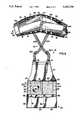
- FIG. 1is a perspective view of the back support of the present invention with a portion of the wearer being shown in phantom.
- FIG. 2is a plan view of the support shown in FIG. 1 showing the top surface of the support, with the support being positioned in a generally horizontal plane.
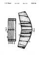
- FIG. 3is a front plan view of the front panel of the second embodiment of the present invention, showing the outer surface;
- FIG. 4is a front plan view of the back panel of the second embodiment showing the inner surface
- FIG. 5is a front plan view of the front panel of the second embodiment showing the inner surface
- FIG. 6is a front plan view of the second embodiment showing the outer surface of the back panel
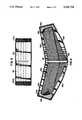
- FIG. 7is a perspective view of the second embodiment showing the elastic band in an unstretched position
- FIG. 8is a perspective view of the second embodiment showing the elastic band in a stretched, supporting position
- FIG. 9is a plan view of a third embodiment of the present invention showing the inside surface
- FIG. 10is an enlarged fragmentary plan view of a portion of the embodiment shown in FIG. 9;
- FIG. 11is a perspective view of the front panel of the embodiment shown in FIG. 9;
- FIG. 12is another perspective of the front panel of the embodiment shown in FIG. 9;
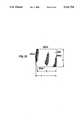
- FIG. 13is a front plan view of one section of the front panel shown in FIG. 9;
- the back support 10includes a waistband 11 having a front panel 12 and a second panel 13. While the combination of the front panel 12 and second panel 13 is referred to as a waistband, it is understood that the waistband 11 is designed to rest below the navel and accordingly, is not defined as being literally a band around the waist, but also may be below the waist.
- a piece of fabricis cut to the size of the second panel 13 and front panel 12. Depending upon the embodiment of the invention to be constructed, the fabric may be of either a stretchable or unstretchable fabric.
- a plurality of semi-rigid stays 15are secured to the second panel 13. On the inside of the second panel 13, next to the wearer, the stays 15 are covered by a rubberized elastic fabric and on the outside by a vinyl fabric. As shown in FIG. 1, two stays 15 are utilized on each half of the second panel 13. A ribbing or binding 18 is stitched across the top and bottom of the entire second panel 13. Loop fabrics 19a and 19b are stitched to the outside of the right and left of the second panel 13.
- the front panel 12is generally rectangular in shape and is constructed from a fabric 12a similar to the fabric used to construct the second panel 13.
- a loop fabric 20is stitched.
- a vinyl member 21is vertically stitched between each half of the front panel 12. The vinyl member is used to cover the stitching between each half of the panel 12. Alternately, only a single piece of fabric 20 may be used, thereby eliminating the need for vinyl member 21.
- rectangular shaped pieces of hook material 22a and 22bare stitched, on the right and left sides respectively, to the underneath side of the front panel 12.
- the stitching 23, 24, 25 and 26, which stitches the material 22a and 22b to the panel 12,is best seen in FIG. 2 and generally defines a rectangle.
- the hook materials 22a and 22b and loop fabrics 19a, 19b and 20may be of any type well known in the industry which would form a hook and loop type fastener such as Velcro® brand.
- the fabric utilized to construct the front panel 12 and second panel 13may be somewhat stretchable, however, the loop fabrics 19a, 19b and 20 are substantially non-stretchable.
- the fabric for the front and second panelsmay be any suitable material such as a stretchable Spandex® material.
- the binding 18may be made of a suitable material such as tricot. A previously stated, if a stretchable material such as Spandex® is utilized, the overall waistband will have some stretchability.
- the waistband 11may expand from one half to three inches and preferably from one and one half to two inches. This allows the waistband 11 to have the capabilities of stretching and conforming to the body of the wearer.
- the second panel 13has a right half 13a and a left half 13b.
- the right halfhas a bottom edge 13c and the left half has a bottom edge 13d.
- the right half 13a and the left half 13bform a generally V-shaped second panel 13.
- Adjustable suspenders, generally designated as 30,are secured to the top edge of the second panel 13 at one end and to the top edge of the apron member 40 at their other end.
- the suspenders 30include a first strap 30a and a second strap 30b.
- Two loop members 41 and 42are stitched to the top of the apron 40 and one of the straps 30a and 30b positioned through the loops 41 and 42 respectively.
- Adjustable buckles 30c and 30dare operatively connected to the straps 30a and 30b, thereby allowing the length of the straps to be adjusted. It is of course understood that other suitable means of similarly connecting the front panel 12 to the second panel 13 may be utilized.
- a four inch wide elastic bandhas a top four inch band 51 and a bottom four inch band 52.
- the top band 51is generally rectangular but has a slight V shape and the bottom band 52 has more of a V shape.
- the bands 51 and 52are connected to each other at their ends by suitable means such as stitching.
- the left ends of the bands 51 and 52have a vinyl piece 54 positioned on the outside surface and a hook material 55 fastened on the bottom surface.
- the right endsare connected and have a vinyl piece 56 on the outside surface and a loop material 58 underneath.
- the bands 51 and 52are held in place, proximate their middle, to the second panel 13 by a rectangular fabric piece 57 which is stitched to the second panel 13.
- the bands 51 and 52are positioned between the fabric 57 and the panel 13.
- Alternative embodiments of similarly connecting the elastic bands 51 and 52 to the panel 13may be utilized, such as those disclosed in U.S. Pat. No. 5,040,524, issued Aug. 20, 1991, and is hereby incorporated by reference.
- Each of the bands 51 and 52may be of any suitable length, such as approximately 24 inches when not stretched. When stretched, this length may be increased to a suitable length so as to provide the necessary support. While the specific design of the support will dictate the length of the stretch desired, it has been found that from 5 to 15 inches and preferably from about 9 to 13 and still more preferably 10 to 12 inches of stretch is desirable.
- An apron portion 40is operatively connected, such as by stitching, to the top of the front panel 12. Since the front panel 12 is positioned proximate the waist, the apron 40 would cover the upper body portion of the wearer. If made from a cloth type material, the apron 40 would protect the wearer from liquid spills, as well as dirt and grease. The apron 40 could also be made from a variety of specialized material to form a special protective barrier to protect the wearer.
- a pocket member 60is operatively connected to the bottom of the front panel 12, by suitable means such as stitching.
- a piece of fabricmay simply be folded upward and then stitched along two seams 61 and 62 to form three open top pockets 63, 64 and 65.
- suitable meansmay be utilized to form pocket members which would depend from the lower portion of the front panel 12.
- the front panel 12, pocket member 60 and apron member 40disposable.
- the pocket member 60may tend to wear out after use and the apron member 40 may tend to become soiled.
- the second panel 13 and elastic band 50tend not to wear out as quickly. Accordingly, it would be advantageous to have the entire front portion replaceable or disposable.
- One convenient way of doing sowould be to have the loops 41 and 42 clipped onto the apron member 40 instead of being stitched. Then, the loop members 41 and 42 could simply be unclipped and a new front portion (pocket member 60, front panel 12 and apron member 40) clipped to the loop members 41 and 42.
- the wearerplaces the suspenders 30 over her shoulders so that the right side 13a is on her right side and the left side 13b is on her left side.
- the front panel 12is not attached to the second panel 13. That is, the support 10 is separated, as shown in FIG. 2.
- the elastic band 50typically will have its hook materials 55 and 58 secured to the loop materials 19a and 19b so that the band 50 would appear as in FIG. 2, without having the end 55 turned up. Then, the wearer would release the ends of the elastic band 50 from the loop materials 19a and 19b.
- the right side 13awould then be pulled toward the right side of the front panel 12 and the hook material 22a would be placed on top of the loop material 19a.
- the left side 13bwould be brought toward the left side of the front panel 12 and the hook material 22b is then placed on top of the loop material 19b, thereby operatively connecting the front panel 12 to the second panel 13.
- the wearergrasps each end of the elastic band by grasping each end of the vinyl tabs 54 and 56 and stretches the elastic band slightly so that the hook material 55 and 58 contacts the loop material 20.
- FIG. 1shows the support 10 on a wearer.
- the V-shaped waistbandis able to be worn by the wearer without having the support ride up as the wearer continues to wear the support 10.
- the apron member 40provides for needed protection in various industries, such as the health care industry where the wearer's clothing may become damaged or soiled.
- the apronwill protect the wearer's clothing from splashes and/or dirt and other contaminants.
- the support 10has a pocket member 60 which allows for the wearer to have access to pockets.
- the support 10would typically cover up the pockets on the normal clothing of the wearer.
- the pocket member 60provides pockets which are quite often necessary for the wearer, especially in the health care industry.
- FIGS. 3-8A second embodiment of the invention is shown in FIGS. 3-8.
- the construction of the components of the back support 110 shown in FIGS. 3-8is very similar to that of the back support 10. The specific details of construction will not be restated here unless they differ from the back support 10.
- the back support 110includes a waistband 111 having a front panel 112 and a second panel 113.
- a plurality of semi-rigid stays 115are secured to the second panel 113.
- a ribbing or binding 118is stitched across the top and bottom of the entire second panel 113.
- Loop fabrics 119a and 119bare stitched to the outside of the right and left sections of the second panel 113.
- the front panel 112is generally rectangular in shape and is constructed from a fabric 112a similar to the fabric used to construct the second panel 113. On the outside surface of the front panel 112, a loop fabric 120 is stitched.
- the loop fabric 120comprises five separate strips 120a, 120b, 120c, 120d and 120e. These separate strips are sewn on the front panel 112 by stitching or other suitable methods. The purpose of the separate strips is to provide the look of a cummerbund.
- the hook materials 122a and 122b and loop materials 119a, 119b, and 120may be of any type well known in the industry which would form a hook and loop fastener, such as Velcro® brand.
- the fabric utilized to construct the front panel 112 and second panel 113may be somewhat stretchable, however, the loop fabrics 119a, 119b and 120 are substantially non-stretchable.
- the fabric for the front and second panels and binding 118are similar to that of the first embodiment.
- the second panel 113has a right half 113a and a left half 113b.
- the right halfhas a bottom edge 113c and the left half has a bottom edge 113d.
- the right half 113a and the left half 113bform a generally V-shaped second panel 113.
- a four inch wide elastic bandgenerally designated as 150, has a top four inch band 151 and a bottom four inch band 152.
- the band 150is substantially identical to the band 50 in the first embodiment and has hook material 155 fastened to both ends on the surface adjacent to the outside surface of the second panel 113.
- five buttons 199are fastened by means well known in the art to the front panel 112.
- the buttons 119, along with the strips of loop material,provide for the appearance of a cummerbund.
- the three main differences between the first and second embodimentsare first that no suspenders are utilized, secondly that there is no apron and finally, that the front panel has a more stylized finish to give a cleaner or neater appearance.
- thisis how the back support 110 would appear when the elastic band 150 is not tightened to a supporting position. In the position as shown in FIG. 7, the major portion of the back support would be covered by a coat worn by the wearer. It is only the cummerbund style front portion of the front panel 112 which would be seen. Then, when support is needed, the elastic band 150 is stretched to the position shown in FIG. 8. There the elastic band 150 would be seen, but this would only be when the extra support is needed.
- FIGS. 9-13A third embodiment of the present invention is shown in FIGS. 9-13.
- the third embodimentis a back support which is designed for use by obese persons.
- the back support 210includes a waistband 211 having a front panel 212 and a second panel 213. While the combination of the front panel 212 and the second panel 213 is referred to as a waistband, it is understood that the waistband 211 is designed to rest below the navel and accordingly, is not defined as being literally a band around the waist, but also may be below the waist.
- a piece of fabricis cut the size of the second panel 213 and the front panel 212. Depending upon the embodiment of the invention to be constructed, the fabric may be either stretchable or unstretchable fabric as discussed with respect to the first embodiment.
- a plurality of semi-rigid stays 215are secured to the second panel 213.
- a ribbing or binding 218is stitched across the top and bottom of the entire second panel 213.
- Loop fabricsare stitched to the outside of the right and left sections of the second panel 213.
- the construction of many components of the third embodimentis similar to the first and will not be repeated here.
- the loop fabrics 219a and 219bare in the same locations as loop fabrics 19a and 19b and 119a and 119b.
- the front panel 212is generally rectangular in shape and is constructed from a fabric 212a similar to the fabric used to construct the second panel 213.
- a loop fabric 220is stitched.
- the loop fabriccovers substantially all of the front panel 212.
- a vinyl member 221is vertically stitched between each half of the front panel 212.
- rectangular pieces of hook material 222a and 222bare stitched on the right and left sides respectively.
- the hook and loop materialsare similar to that used in the other embodiments.
- the fabric used to construct the front panel 212 and second panel 213may be somewhat stretchable, however, the loop fabrics are substantially non-stretchable.
- the fabric for the front and second panelsmay be any suitable material such as stretchable Spandex® material and the binding may be made from suitable material such as Tricot®.
- the second panel 213has a right half 213a and a left half 213b.
- the right halfhas a bottom edge 213c and the left half has a bottom edge 213d.
- the right half 213a and the left half 213bform a generally V-shaped second panel 213.
- a four inch wide elastic band 251is similar to the bands 51 and 151 previously described.
- An elastic strip 270operatively loosely connects the front panel to the second panel.
- the elastic stripis approximately four inches in length and has a first end 270a stitched to the second panel 213 and a second end 270b stitched to the front panel 212.
- This elastic band 270only loosely connects the two panels and the hook and loop fasteners are still utilized to secure the panels together.
- the elastic strip 270aids in the positioning of the two panels when the back support 210 is being put on by the wearer.
- the elastic strip 270does not secure the two panels tightly to each other.
- the hook and loop fastenersare utilized for this purpose.
- the front panel 212comprises a first section 290 and a second section 295.
- the first section 290is shown in FIG. 13.
- the other section 295is a mirror image thereof and will not be described in more detail.
- the first section 290is generally rectangular in shape and has a top edge 290a generally parallel to a bottom edge 290b.
- a right edge 290cis generally perpendicular to the top edge 290a and the bottom edge 290b.
- the left edge 290dis slightly curved outward away from the edge 290c. Thereby, the width of the section 290 is greater in the middle than at the top and bottom edges.
- the height "H"may be any suitable height, but in one embodiment, would be approximately nine and one-half inches.
- the length at the top and bottom, or the designation "X" in FIG. 13,is approximately eleven inches.
- the wider width at the center or "Y"is approximately eleven and three-fourths inches.
- the extra widthwould be from three-fourths to one inch greater than the width at the edges.
- the panel 290is generally planar before attachment to the other section 295.
- the edge 290dis operatively connected by suitable means, such as stitching, to a vinyl piece 297.
- a stay(not shown) may be positioned in the vinyl piece 297.
- the edge 295dis likewise sewn to the vinyl strip 297, as best seen in FIG. 11.
- the second embodiment of back support 110is substantially similar to the first embodiment, except for the lack of suspenders.
- One side of the front panel 112is connected to the second panel 13 by having the hook material 122a connect to the loop materials 119a.
- the second panel 113is positioned around the wearer's back and the other side of the front panel 112 is connected to the back panel around the front of the wearer and the hook material 122b contacts the loop material 119b.
- the wearermay make the final adjustments so that the front panel 112 and second panel 113 are comfortable around the wearer's midsection. If the wearer then wants additional support, the band 150 is stretched and moved to the position shown in FIG. 8 by initially releasing the band from the front panel 112 (as in FIG. 7) and extending it closer to the centerline of the front panel 112.
- the back section 213is positioned around the back of the wearer and then the front section 212 is wrapped around the front of the wearer and hook material 222a comes in contact with the loop material 219a, thereby securing one end of the front panel 212 to the second panel 213. Then, the hook material 222b is moved over the loop material 219b and pressed down to firmly secure the support in position.
- the elastic band 270maintains a loose connection between the one end of the second panel 213 and front panel 212 before the hook and loop material are fastened. The actual distance that the front panel overlaps the second panel will determined by the size of the wearer and the wearer can make the necessary adjustments so that it is comfortable. Then, the operation of the elastic band 251 is similar to the other embodiments and is stretched to provide additional support as previously discussed.
- the front panel 212has a convex portion proximate its center (around the vinyl strip 297).
- the convex portioncups the fat tissue of the obese wearer and lifts and supports the fat tissue to provide increased abdominal support.
- the convex portioncups or cradles the fat tissue, not only is the abdominal support increased, but also the lower back support is also increased when the fat tissue is lifted and support.
- the convex portion which is conformable to the fat tissue of the weareris shown as being constructed from two generally flat, planar pieces of material. It is the curved edge which, when sewn together, provides for the cup configuration. It is of course understood that other suitable means of constructing such a cup may be utilized.
Landscapes
- Health & Medical Sciences (AREA)
- Nursing (AREA)
- Orthopedic Medicine & Surgery (AREA)
- Engineering & Computer Science (AREA)
- Biomedical Technology (AREA)
- Heart & Thoracic Surgery (AREA)
- Vascular Medicine (AREA)
- Life Sciences & Earth Sciences (AREA)
- Animal Behavior & Ethology (AREA)
- General Health & Medical Sciences (AREA)
- Public Health (AREA)
- Veterinary Medicine (AREA)
- Orthopedics, Nursing, And Contraception (AREA)
Abstract
Description
Claims (14)
Priority Applications (4)
| Application Number | Priority Date | Filing Date | Title |
|---|---|---|---|
| US07/872,440US5241704A (en) | 1991-04-23 | 1992-04-23 | Back support |
| AU32122/93AAU3212293A (en) | 1992-04-23 | 1993-01-29 | Back support |
| EP93101470AEP0566827A1 (en) | 1992-04-23 | 1993-01-30 | Back support |
| CA002089213ACA2089213A1 (en) | 1992-04-23 | 1993-02-10 | Back support |
Applications Claiming Priority (2)
| Application Number | Priority Date | Filing Date | Title |
|---|---|---|---|
| US07/689,980US5148549A (en) | 1991-04-23 | 1991-04-23 | Back support with side openings and attached apron |
| US07/872,440US5241704A (en) | 1991-04-23 | 1992-04-23 | Back support |
Related Parent Applications (1)
| Application Number | Title | Priority Date | Filing Date |
|---|---|---|---|
| US07/689,980Continuation-In-PartUS5148549A (en) | 1991-04-23 | 1991-04-23 | Back support with side openings and attached apron |
Publications (1)
| Publication Number | Publication Date |
|---|---|
| US5241704Atrue US5241704A (en) | 1993-09-07 |
Family
ID=25359580
Family Applications (1)
| Application Number | Title | Priority Date | Filing Date |
|---|---|---|---|
| US07/872,440Expired - Fee RelatedUS5241704A (en) | 1991-04-23 | 1992-04-23 | Back support |
Country Status (4)
| Country | Link |
|---|---|
| US (1) | US5241704A (en) |
| EP (1) | EP0566827A1 (en) |
| AU (1) | AU3212293A (en) |
| CA (1) | CA2089213A1 (en) |
Cited By (31)
| Publication number | Priority date | Publication date | Assignee | Title |
|---|---|---|---|---|
| USD349767S (en) | 1991-12-06 | 1994-08-16 | Etsthuasne & Cie | Retention belt |
| US5560046A (en)* | 1994-03-25 | 1996-10-01 | Iwamasa; Yukio | Lumbar support belt with suspenders and elastic sections having different elasticities |
| USD374547S (en) | 1994-08-23 | 1996-10-15 | Scott Specialties Inc. | Back support belt |
| US5611084A (en)* | 1994-02-28 | 1997-03-18 | Raven Industries, Inc. | Jacket with integral back support |
| US5656020A (en)* | 1992-07-02 | 1997-08-12 | Greengarg; Gerson M. | Lifting belt, panel and method |
| US5785672A (en)* | 1997-05-20 | 1998-07-28 | Core Products International, Inc. | Lumbosacral support belts and method |
| US5833638A (en)* | 1996-06-10 | 1998-11-10 | Nelson; Ronald E. | Back brace |
| US5853378A (en)* | 1997-10-02 | 1998-12-29 | Modglin; Michael D. | Lumbo-Sacral orthosis |
| US6048253A (en)* | 1997-06-05 | 2000-04-11 | Larsen; Marilyn M. | Support apparatus |
| USD422709S (en)* | 1995-08-03 | 2000-04-11 | Ok-1 Manufacturing Company | Back support belt |
| US6071175A (en)* | 1998-11-16 | 2000-06-06 | Cmo, Inc. | Natal support |
| WO2000062642A1 (en)* | 1999-04-19 | 2000-10-26 | Outdoor Medical Research, Llc | Backpack with abdominal support system |
| US6243883B1 (en)* | 2000-07-20 | 2001-06-12 | Lisa Boggs | Soccer protective gear |
| USD447603S1 (en) | 2000-02-01 | 2001-09-04 | Fla Orthopedics, Inc. | Back support and detachable apron |
| USD464467S1 (en) | 2000-03-06 | 2002-10-15 | Fla Orthopedics, Inc. | Back support and detachable apron |
| US6666838B2 (en) | 2002-04-22 | 2003-12-23 | Deroyal Industries, Inc. | Low-profile lumbo-sacral orthosis |
| CN101785589A (en)* | 2010-03-19 | 2010-07-28 | 陈伟强 | Novel health care waistband |
| US20100275339A1 (en)* | 2009-04-29 | 2010-11-04 | Angela Huc | Body Cover Wrap |
| US20100318010A1 (en)* | 2007-10-17 | 2010-12-16 | Sandifer Alan T | Adjustable posterior spinal orthosis |
| US20110119802A1 (en)* | 2009-08-20 | 2011-05-26 | Frederick Alan Schuck | Apron |
| US8328742B2 (en) | 2009-09-25 | 2012-12-11 | Medical Technology Inc. | Adjustable orthopedic back brace |
| US20130067642A1 (en)* | 2011-09-21 | 2013-03-21 | William Chen | Maternity belt structure |
| US20130072087A1 (en)* | 2011-09-21 | 2013-03-21 | William Chen | Adjustable protective maternity belt |
| EP2583571A1 (en)* | 2011-10-21 | 2013-04-24 | Daniel Elliott | Improvements relating to chaps |
| WO2013132180A1 (en)* | 2012-03-08 | 2013-09-12 | Gibaud | Lumbar support belt |
| US8808213B2 (en) | 2010-05-28 | 2014-08-19 | Hendricks Orthotic Prosthetic Enterprises, Inc. | Mechanically advantaged spinal system and method |
| US20170020708A1 (en)* | 2015-07-24 | 2017-01-26 | Billy Forest Dye | Abdominal and Thoracic Binder |
| IT201600116446A1 (en)* | 2016-11-17 | 2018-05-17 | Pavis S P A | ACCESSORY FOR THE RACE |
| CN112891036A (en)* | 2021-03-23 | 2021-06-04 | 上海交通大学医学院附属第九人民医院 | Waistline with 3D printing support bar |
| US20220079277A1 (en)* | 2020-09-16 | 2022-03-17 | Ferro Concepts Inc. | Removable expandable semirigid cummerbund |
| US11324622B1 (en) | 2019-08-08 | 2022-05-10 | Preferred Prescription, Inc. | Back brace belt and apparatus, and method of belt length adjustment therefor |
Families Citing this family (1)
| Publication number | Priority date | Publication date | Assignee | Title |
|---|---|---|---|---|
| ES2264340B1 (en)* | 2004-09-09 | 2008-06-16 | Angustias Cuesta Obispo | ABDOMEN LIFTING DEVICE. |
Citations (57)
| Publication number | Priority date | Publication date | Assignee | Title |
|---|---|---|---|---|
| US184153A (en)* | 1876-11-07 | Improvement in abdominal supporters | ||
| US468425A (en)* | 1892-02-09 | Shoulder-brace | ||
| US472086A (en)* | 1892-04-05 | Shoulder-brace | ||
| US572465A (en)* | 1896-12-01 | Abdominal supporter | ||
| US657133A (en)* | 1900-05-02 | 1900-09-04 | Jennie Atkins Redick | Apparel-corset. |
| US811167A (en)* | 1905-08-25 | 1906-01-30 | Milan L Paddock | Protector for backs and chests. |
| US933610A (en)* | 1909-04-09 | 1909-09-07 | Irene Yanowsky | Corset. |
| US934625A (en)* | 1908-07-22 | 1909-09-21 | Angele Petrel | Abdominal bandage. |
| US1006862A (en)* | 1908-09-26 | 1911-10-24 | American Corset Stay Company | Corset-stay. |
| US1006863A (en)* | 1910-03-21 | 1911-10-24 | American Corset Stay Company | Corset. |
| US1469069A (en)* | 1921-10-22 | 1923-09-25 | Abraham J Freedenberg | Abdominal supporter |
| US1565808A (en)* | 1922-09-26 | 1925-12-15 | Model Brassiere Company Inc | Maternity garment |
| FR615269A (en)* | 1926-04-29 | 1927-01-04 | Belt with interchangeable abdominal piece | |
| US1768223A (en)* | 1927-10-12 | 1930-06-24 | Standard Corset Company | Body support and method of producing same |
| US1776864A (en)* | 1928-11-24 | 1930-09-30 | Taylor M Cameron | Truss |
| US1983636A (en)* | 1932-07-09 | 1934-12-11 | Lewis F Palkens | Combined elastic belt and suspenders |
| US2104699A (en)* | 1936-08-03 | 1938-01-04 | Avery Jenkins N | Surgical appliance |
| US2282021A (en)* | 1940-02-20 | 1942-05-05 | Benningfield Thomas | Truss and abdominal support |
| US2426931A (en)* | 1945-12-07 | 1947-09-02 | Josephine L Holt | Abdominal support |
| US2461208A (en)* | 1946-03-08 | 1949-02-08 | Goforth Lula | Abdominal bandage |
| US2749550A (en)* | 1954-10-28 | 1956-06-12 | Surgical Appliance Ind | Abdominal support |
| US2813526A (en)* | 1956-06-29 | 1957-11-19 | Milford H Beebe | Orthopedic appliance |
| US2840822A (en)* | 1956-10-26 | 1958-07-01 | Francis S Ericsson | Abdominal supporting belt |
| US2981258A (en)* | 1957-04-30 | 1961-04-25 | Nu Lift Co Inc | Maternity girdle |
| US3052236A (en)* | 1959-07-23 | 1962-09-04 | Herbert S Schrieber | Spinal column supporter |
| US3101718A (en)* | 1961-05-05 | 1963-08-27 | Rocker Paula Blatt | Combination garter supporter and back and abdomen supporting means |
| US3116735A (en)* | 1960-08-11 | 1964-01-07 | Freeman Mfg Company | Posture brace |
| US3298366A (en)* | 1964-12-14 | 1967-01-17 | Emory S Moore | Surgical abdominal binder |
| US3441027A (en)* | 1968-07-18 | 1969-04-29 | Ira S Lehman | Compound support |
| US3521623A (en)* | 1965-02-12 | 1970-07-28 | Wayne Nichols | Back brace |
| US3554190A (en)* | 1968-08-15 | 1971-01-12 | David Kaplan | Back, shoulder and stomach support |
| US3603316A (en)* | 1970-05-08 | 1971-09-07 | Ira S Lehman | Abdominal belt |
| US3605731A (en)* | 1968-11-02 | 1971-09-20 | Tigges Manfred | Device for support,correction and treatment of the human spinal column |
| US3623488A (en)* | 1969-08-15 | 1971-11-30 | Takeo Nakayama | Belly-band |
| US3754549A (en)* | 1971-06-29 | 1973-08-28 | Enterprises H | Truss |
| US3920008A (en)* | 1974-08-08 | 1975-11-18 | Ira S Lehman | Support belt |
| US3931816A (en)* | 1975-01-07 | 1976-01-13 | Jacobo Waldmann | Adjustable antiptosis corset |
| US4108149A (en)* | 1977-01-06 | 1978-08-22 | Castiglia Ignatius F | Maternity brace |
| US4325379A (en)* | 1980-12-17 | 1982-04-20 | Ozbey Ahmet M | Derriere exerciser |
| EP0055238A1 (en)* | 1980-12-22 | 1982-06-30 | Strömbergs Sadelmakeri AB | Lifting and carrying aid |
| US4545370A (en)* | 1983-09-14 | 1985-10-08 | Welsh Thomas M | Kinetic back support belt |
| US4572167A (en)* | 1981-03-25 | 1986-02-25 | Sumner Brunswick | Orthopedic device and process |
| US4709692A (en)* | 1986-07-02 | 1987-12-01 | Kirschenberg Bruce H | Thigh mounted lower back support belt |
| US4768499A (en)* | 1987-02-17 | 1988-09-06 | Kemp Kenneth A | Back and abdominal muscle supporting belt |
| US4782535A (en)* | 1987-11-23 | 1988-11-08 | Edward H. Yewer | Belt |
| US4836194A (en)* | 1986-08-29 | 1989-06-06 | Safeguard Industrial Corporation | Therapeutic lumbosacral appliance |
| US4866789A (en)* | 1983-11-21 | 1989-09-19 | Dormco, Inc. | Protective body suit |
| US4881528A (en)* | 1988-10-21 | 1989-11-21 | Henry Scott | Spinal traction and support unit used while seated |
| US4907576A (en)* | 1989-01-18 | 1990-03-13 | Curlee James D | Orthopaedic device using non-stretch material and method for its manufacture |
| US4981307A (en)* | 1988-02-18 | 1991-01-01 | Walsh Andrew C | Suspension harness/body jacket arrangement |
| US4993409A (en)* | 1989-02-08 | 1991-02-19 | Royce Medical Company | Back support |
| US5007412A (en)* | 1990-06-11 | 1991-04-16 | Dewall Terry L | Back support vest |
| US5038760A (en)* | 1990-03-01 | 1991-08-13 | Osborn Margaret R | Surgical orthopedic back support garment |
| US5040524A (en)* | 1990-04-30 | 1991-08-20 | Ergodyne Corporation | Back support |
| US5070866A (en)* | 1990-10-25 | 1991-12-10 | Alexander William K | Woven back support belt with rigidity control |
| US5147261A (en)* | 1991-03-06 | 1992-09-15 | Florida Orthopedics, Inc. | Lifting belt |
| US5148549A (en)* | 1991-04-23 | 1992-09-22 | Ergodyne Corporation | Back support with side openings and attached apron |
Family Cites Families (2)
| Publication number | Priority date | Publication date | Assignee | Title |
|---|---|---|---|---|
| US571172A (en)* | 1896-11-10 | Bandage | ||
| GB765416A (en)* | 1955-02-28 | 1957-01-09 | Spencer Banbury Ltd | An improved lumbar traction harness |
- 1992
- 1992-04-23USUS07/872,440patent/US5241704A/ennot_activeExpired - Fee Related
- 1993
- 1993-01-29AUAU32122/93Apatent/AU3212293A/ennot_activeAbandoned
- 1993-01-30EPEP93101470Apatent/EP0566827A1/ennot_activeWithdrawn
- 1993-02-10CACA002089213Apatent/CA2089213A1/ennot_activeAbandoned
Patent Citations (57)
| Publication number | Priority date | Publication date | Assignee | Title |
|---|---|---|---|---|
| US468425A (en)* | 1892-02-09 | Shoulder-brace | ||
| US472086A (en)* | 1892-04-05 | Shoulder-brace | ||
| US572465A (en)* | 1896-12-01 | Abdominal supporter | ||
| US184153A (en)* | 1876-11-07 | Improvement in abdominal supporters | ||
| US657133A (en)* | 1900-05-02 | 1900-09-04 | Jennie Atkins Redick | Apparel-corset. |
| US811167A (en)* | 1905-08-25 | 1906-01-30 | Milan L Paddock | Protector for backs and chests. |
| US934625A (en)* | 1908-07-22 | 1909-09-21 | Angele Petrel | Abdominal bandage. |
| US1006862A (en)* | 1908-09-26 | 1911-10-24 | American Corset Stay Company | Corset-stay. |
| US933610A (en)* | 1909-04-09 | 1909-09-07 | Irene Yanowsky | Corset. |
| US1006863A (en)* | 1910-03-21 | 1911-10-24 | American Corset Stay Company | Corset. |
| US1469069A (en)* | 1921-10-22 | 1923-09-25 | Abraham J Freedenberg | Abdominal supporter |
| US1565808A (en)* | 1922-09-26 | 1925-12-15 | Model Brassiere Company Inc | Maternity garment |
| FR615269A (en)* | 1926-04-29 | 1927-01-04 | Belt with interchangeable abdominal piece | |
| US1768223A (en)* | 1927-10-12 | 1930-06-24 | Standard Corset Company | Body support and method of producing same |
| US1776864A (en)* | 1928-11-24 | 1930-09-30 | Taylor M Cameron | Truss |
| US1983636A (en)* | 1932-07-09 | 1934-12-11 | Lewis F Palkens | Combined elastic belt and suspenders |
| US2104699A (en)* | 1936-08-03 | 1938-01-04 | Avery Jenkins N | Surgical appliance |
| US2282021A (en)* | 1940-02-20 | 1942-05-05 | Benningfield Thomas | Truss and abdominal support |
| US2426931A (en)* | 1945-12-07 | 1947-09-02 | Josephine L Holt | Abdominal support |
| US2461208A (en)* | 1946-03-08 | 1949-02-08 | Goforth Lula | Abdominal bandage |
| US2749550A (en)* | 1954-10-28 | 1956-06-12 | Surgical Appliance Ind | Abdominal support |
| US2813526A (en)* | 1956-06-29 | 1957-11-19 | Milford H Beebe | Orthopedic appliance |
| US2840822A (en)* | 1956-10-26 | 1958-07-01 | Francis S Ericsson | Abdominal supporting belt |
| US2981258A (en)* | 1957-04-30 | 1961-04-25 | Nu Lift Co Inc | Maternity girdle |
| US3052236A (en)* | 1959-07-23 | 1962-09-04 | Herbert S Schrieber | Spinal column supporter |
| US3116735A (en)* | 1960-08-11 | 1964-01-07 | Freeman Mfg Company | Posture brace |
| US3101718A (en)* | 1961-05-05 | 1963-08-27 | Rocker Paula Blatt | Combination garter supporter and back and abdomen supporting means |
| US3298366A (en)* | 1964-12-14 | 1967-01-17 | Emory S Moore | Surgical abdominal binder |
| US3521623A (en)* | 1965-02-12 | 1970-07-28 | Wayne Nichols | Back brace |
| US3441027A (en)* | 1968-07-18 | 1969-04-29 | Ira S Lehman | Compound support |
| US3554190A (en)* | 1968-08-15 | 1971-01-12 | David Kaplan | Back, shoulder and stomach support |
| US3605731A (en)* | 1968-11-02 | 1971-09-20 | Tigges Manfred | Device for support,correction and treatment of the human spinal column |
| US3623488A (en)* | 1969-08-15 | 1971-11-30 | Takeo Nakayama | Belly-band |
| US3603316A (en)* | 1970-05-08 | 1971-09-07 | Ira S Lehman | Abdominal belt |
| US3754549A (en)* | 1971-06-29 | 1973-08-28 | Enterprises H | Truss |
| US3920008A (en)* | 1974-08-08 | 1975-11-18 | Ira S Lehman | Support belt |
| US3931816A (en)* | 1975-01-07 | 1976-01-13 | Jacobo Waldmann | Adjustable antiptosis corset |
| US4108149A (en)* | 1977-01-06 | 1978-08-22 | Castiglia Ignatius F | Maternity brace |
| US4325379A (en)* | 1980-12-17 | 1982-04-20 | Ozbey Ahmet M | Derriere exerciser |
| EP0055238A1 (en)* | 1980-12-22 | 1982-06-30 | Strömbergs Sadelmakeri AB | Lifting and carrying aid |
| US4572167A (en)* | 1981-03-25 | 1986-02-25 | Sumner Brunswick | Orthopedic device and process |
| US4545370A (en)* | 1983-09-14 | 1985-10-08 | Welsh Thomas M | Kinetic back support belt |
| US4866789A (en)* | 1983-11-21 | 1989-09-19 | Dormco, Inc. | Protective body suit |
| US4709692A (en)* | 1986-07-02 | 1987-12-01 | Kirschenberg Bruce H | Thigh mounted lower back support belt |
| US4836194A (en)* | 1986-08-29 | 1989-06-06 | Safeguard Industrial Corporation | Therapeutic lumbosacral appliance |
| US4768499A (en)* | 1987-02-17 | 1988-09-06 | Kemp Kenneth A | Back and abdominal muscle supporting belt |
| US4782535A (en)* | 1987-11-23 | 1988-11-08 | Edward H. Yewer | Belt |
| US4981307A (en)* | 1988-02-18 | 1991-01-01 | Walsh Andrew C | Suspension harness/body jacket arrangement |
| US4881528A (en)* | 1988-10-21 | 1989-11-21 | Henry Scott | Spinal traction and support unit used while seated |
| US4907576A (en)* | 1989-01-18 | 1990-03-13 | Curlee James D | Orthopaedic device using non-stretch material and method for its manufacture |
| US4993409A (en)* | 1989-02-08 | 1991-02-19 | Royce Medical Company | Back support |
| US5038760A (en)* | 1990-03-01 | 1991-08-13 | Osborn Margaret R | Surgical orthopedic back support garment |
| US5040524A (en)* | 1990-04-30 | 1991-08-20 | Ergodyne Corporation | Back support |
| US5007412A (en)* | 1990-06-11 | 1991-04-16 | Dewall Terry L | Back support vest |
| US5070866A (en)* | 1990-10-25 | 1991-12-10 | Alexander William K | Woven back support belt with rigidity control |
| US5147261A (en)* | 1991-03-06 | 1992-09-15 | Florida Orthopedics, Inc. | Lifting belt |
| US5148549A (en)* | 1991-04-23 | 1992-09-22 | Ergodyne Corporation | Back support with side openings and attached apron |
Non-Patent Citations (3)
| Title |
|---|
| CompVest Back Support Brochure, 1984 of Comp Equipment Corporation (now known as Ergodyne Corporation).* |
| English translation of French Patent No. 2,597,332.* |
| European Search Reoprt EP 91 10 1967.* |
Cited By (39)
| Publication number | Priority date | Publication date | Assignee | Title |
|---|---|---|---|---|
| USD349767S (en) | 1991-12-06 | 1994-08-16 | Etsthuasne & Cie | Retention belt |
| US5656020A (en)* | 1992-07-02 | 1997-08-12 | Greengarg; Gerson M. | Lifting belt, panel and method |
| US5611084A (en)* | 1994-02-28 | 1997-03-18 | Raven Industries, Inc. | Jacket with integral back support |
| US5560046A (en)* | 1994-03-25 | 1996-10-01 | Iwamasa; Yukio | Lumbar support belt with suspenders and elastic sections having different elasticities |
| USD374547S (en) | 1994-08-23 | 1996-10-15 | Scott Specialties Inc. | Back support belt |
| USD422709S (en)* | 1995-08-03 | 2000-04-11 | Ok-1 Manufacturing Company | Back support belt |
| US5833638A (en)* | 1996-06-10 | 1998-11-10 | Nelson; Ronald E. | Back brace |
| US5785672A (en)* | 1997-05-20 | 1998-07-28 | Core Products International, Inc. | Lumbosacral support belts and method |
| US6048253A (en)* | 1997-06-05 | 2000-04-11 | Larsen; Marilyn M. | Support apparatus |
| US5967998A (en)* | 1997-10-02 | 1999-10-19 | Modglin; Michael D. | Lumbo-sacral orthosis |
| US5853378A (en)* | 1997-10-02 | 1998-12-29 | Modglin; Michael D. | Lumbo-Sacral orthosis |
| US6071175A (en)* | 1998-11-16 | 2000-06-06 | Cmo, Inc. | Natal support |
| WO2000062642A1 (en)* | 1999-04-19 | 2000-10-26 | Outdoor Medical Research, Llc | Backpack with abdominal support system |
| GB2364631A (en)* | 1999-04-19 | 2002-02-06 | Outdoor Medical Res Llc | Backpack with abdominal support sytem |
| US6364186B1 (en) | 1999-04-19 | 2002-04-02 | Outdoor Medical Research Llc | Backpack with abdominal support system |
| USD447603S1 (en) | 2000-02-01 | 2001-09-04 | Fla Orthopedics, Inc. | Back support and detachable apron |
| USD464467S1 (en) | 2000-03-06 | 2002-10-15 | Fla Orthopedics, Inc. | Back support and detachable apron |
| US6243883B1 (en)* | 2000-07-20 | 2001-06-12 | Lisa Boggs | Soccer protective gear |
| US6666838B2 (en) | 2002-04-22 | 2003-12-23 | Deroyal Industries, Inc. | Low-profile lumbo-sacral orthosis |
| US20100318010A1 (en)* | 2007-10-17 | 2010-12-16 | Sandifer Alan T | Adjustable posterior spinal orthosis |
| US20100275339A1 (en)* | 2009-04-29 | 2010-11-04 | Angela Huc | Body Cover Wrap |
| US20110119802A1 (en)* | 2009-08-20 | 2011-05-26 | Frederick Alan Schuck | Apron |
| WO2011022711A3 (en)* | 2009-08-20 | 2011-06-30 | Frederick Alan Schuck | Apron |
| US8328742B2 (en) | 2009-09-25 | 2012-12-11 | Medical Technology Inc. | Adjustable orthopedic back brace |
| CN101785589A (en)* | 2010-03-19 | 2010-07-28 | 陈伟强 | Novel health care waistband |
| US8808213B2 (en) | 2010-05-28 | 2014-08-19 | Hendricks Orthotic Prosthetic Enterprises, Inc. | Mechanically advantaged spinal system and method |
| US20130067642A1 (en)* | 2011-09-21 | 2013-03-21 | William Chen | Maternity belt structure |
| US20130072087A1 (en)* | 2011-09-21 | 2013-03-21 | William Chen | Adjustable protective maternity belt |
| EP2583571A1 (en)* | 2011-10-21 | 2013-04-24 | Daniel Elliott | Improvements relating to chaps |
| FR2987739A1 (en)* | 2012-03-08 | 2013-09-13 | Gibaud | LUMBAR SUPPORT BELT |
| WO2013132180A1 (en)* | 2012-03-08 | 2013-09-12 | Gibaud | Lumbar support belt |
| US20170020708A1 (en)* | 2015-07-24 | 2017-01-26 | Billy Forest Dye | Abdominal and Thoracic Binder |
| IT201600116446A1 (en)* | 2016-11-17 | 2018-05-17 | Pavis S P A | ACCESSORY FOR THE RACE |
| EP3323311A1 (en) | 2016-11-17 | 2018-05-23 | Pavis S.P.A. | Running accessory |
| US11324622B1 (en) | 2019-08-08 | 2022-05-10 | Preferred Prescription, Inc. | Back brace belt and apparatus, and method of belt length adjustment therefor |
| US12357490B2 (en) | 2019-08-08 | 2025-07-15 | Preferred Prescription, Inc. | Back brace with enhanced height support and adjustment capability |
| US20220079277A1 (en)* | 2020-09-16 | 2022-03-17 | Ferro Concepts Inc. | Removable expandable semirigid cummerbund |
| US11805832B2 (en)* | 2020-09-16 | 2023-11-07 | Ferro Concepts Inc. | Removable expandable semirigid cummerbund |
| CN112891036A (en)* | 2021-03-23 | 2021-06-04 | 上海交通大学医学院附属第九人民医院 | Waistline with 3D printing support bar |
Also Published As
| Publication number | Publication date |
|---|---|
| CA2089213A1 (en) | 1993-10-24 |
| AU3212293A (en) | 1993-10-28 |
| EP0566827A1 (en) | 1993-10-27 |
Similar Documents
| Publication | Publication Date | Title |
|---|---|---|
| US5241704A (en) | Back support | |
| US5148549A (en) | Back support with side openings and attached apron | |
| US5176131A (en) | Back support | |
| US5040524A (en) | Back support | |
| US10159357B2 (en) | Baby carrier | |
| US6918885B2 (en) | Vest having arm sling | |
| US6406449B1 (en) | Vest having arm sling | |
| US5188585A (en) | Lumbo-sacral orthopedic support | |
| US5548843A (en) | Back support with means to secure the belt on the wearer while in an open position | |
| US6068606A (en) | Back support belt | |
| US5656021A (en) | Detachable back, belt, apron, method | |
| US6102877A (en) | Arm sling | |
| US5950894A (en) | Backpack assembly | |
| US6719712B2 (en) | Support device for supporting the back, hips, upper thighs and groin areas | |
| US6435185B1 (en) | Travelers' comfort—wearable arm support | |
| US5762619A (en) | Fashion belt with built-in lumbar support | |
| US4108149A (en) | Maternity brace | |
| US6907620B2 (en) | Belt load distribution device | |
| GB2260270A (en) | An abdominal and lower back support device for a pregnant woman | |
| US4867145A (en) | Abdominal and pelvic area support | |
| US20030212355A1 (en) | Multi-purpose back brace | |
| JP7376074B2 (en) | trousers with supports | |
| EP3875064A1 (en) | Back brace | |
| JP6352335B2 (en) | Pants with pelvic belt | |
| GB2582302A (en) | A garment device |
Legal Events
| Date | Code | Title | Description |
|---|---|---|---|
| AS | Assignment | Owner name:ERGODYNE CORPORATION A CORPORATION OF MN, MINNE Free format text:ASSIGNMENT OF ASSIGNORS INTEREST.;ASSIGNOR:SYDOR, ROBIN M.;REEL/FRAME:006110/0462 Effective date:19920423 | |
| CC | Certificate of correction | ||
| FEPP | Fee payment procedure | Free format text:PAYOR NUMBER ASSIGNED (ORIGINAL EVENT CODE: ASPN); ENTITY STATUS OF PATENT OWNER: SMALL ENTITY | |
| FPAY | Fee payment | Year of fee payment:4 | |
| FPAY | Fee payment | Year of fee payment:8 | |
| AS | Assignment | Owner name:WELLS FARGO BANK MINNESOTA, NATIONAL ASSOCIATION, Free format text:SECURITY INTEREST;ASSIGNOR:ERGODYNE CORPORATION;REEL/FRAME:012166/0624 Effective date:20010627 | |
| AS | Assignment | Owner name:WELLS FARGO BANK MINNESOTA, MINNESOTA Free format text:RELEASE OF SECURITY INTEREST;ASSIGNOR:ERGODYNE CORPORATION;REEL/FRAME:013922/0680 Effective date:20030825 | |
| AS | Assignment | Owner name:WELLS FARGO BANK MINNESOTA, NATIONAL ASSOICATION, Free format text:RELEASE OF SECURITY INTEREST PREVIOUSLY RECORDED ON REEL 012166 FRAME 0624.;ASSIGNOR:ERGODYNE CORPORATION;REEL/FRAME:013974/0940 Effective date:20030825 | |
| REMI | Maintenance fee reminder mailed | ||
| LAPS | Lapse for failure to pay maintenance fees | ||
| STCH | Information on status: patent discontinuation | Free format text:PATENT EXPIRED DUE TO NONPAYMENT OF MAINTENANCE FEES UNDER 37 CFR 1.362 | |
| FP | Lapsed due to failure to pay maintenance fee | Effective date:20050907 |