US5241525A - Digital optical disc encoder system - Google Patents
Digital optical disc encoder systemDownload PDFInfo
- Publication number
- US5241525A US5241525AUS07/769,290US76929091AUS5241525AUS 5241525 AUS5241525 AUS 5241525AUS 76929091 AUS76929091 AUS 76929091AUS 5241525 AUS5241525 AUS 5241525A
- Authority
- US
- United States
- Prior art keywords
- disc
- recording
- information
- transport system
- control
- Prior art date
- Legal status (The legal status is an assumption and is not a legal conclusion. Google has not performed a legal analysis and makes no representation as to the accuracy of the status listed.)
- Expired - Lifetime
Links
- 230000003287optical effectEffects0.000titleclaimsabstractdescription48
- 238000000034methodMethods0.000claimsabstractdescription11
- 238000007639printingMethods0.000claimsdescription25
- 230000003213activating effectEffects0.000claims1
- 230000001351cycling effectEffects0.000claims1
- 238000007641inkjet printingMethods0.000abstractdescription8
- 238000010276constructionMethods0.000abstractdescription2
- 230000008569processEffects0.000abstractdescription2
- 230000032258transportEffects0.000description32
- 238000010304firingMethods0.000description6
- 230000008901benefitEffects0.000description4
- 238000006073displacement reactionMethods0.000description3
- 230000000694effectsEffects0.000description2
- 230000001939inductive effectEffects0.000description2
- 238000004519manufacturing processMethods0.000description2
- 230000015572biosynthetic processEffects0.000description1
- 230000001010compromised effectEffects0.000description1
- 238000005516engineering processMethods0.000description1
- 230000006872improvementEffects0.000description1
- 230000006698inductionEffects0.000description1
- 230000001788irregularEffects0.000description1
- 230000007246mechanismEffects0.000description1
- 238000002360preparation methodMethods0.000description1
- 230000009467reductionEffects0.000description1
- 230000003068static effectEffects0.000description1
- 230000007723transport mechanismEffects0.000description1
Images


Classifications
- B—PERFORMING OPERATIONS; TRANSPORTING
- B41—PRINTING; LINING MACHINES; TYPEWRITERS; STAMPS
- B41J—TYPEWRITERS; SELECTIVE PRINTING MECHANISMS, i.e. MECHANISMS PRINTING OTHERWISE THAN FROM A FORME; CORRECTION OF TYPOGRAPHICAL ERRORS
- B41J11/00—Devices or arrangements of selective printing mechanisms, e.g. ink-jet printers or thermal printers, for supporting or handling copy material in sheet or web form
- B41J11/36—Blanking or long feeds; Feeding to a particular line, e.g. by rotation of platen or feed roller
- B41J11/42—Controlling printing material conveyance for accurate alignment of the printing material with the printhead; Print registering
- B41J11/44—Controlling printing material conveyance for accurate alignment of the printing material with the printhead; Print registering by devices, e.g. programme tape or contact wheel, moved in correspondence with movement of paper-feeding devices, e.g. platen rotation
Definitions
- This inventionrelates to position transducers and rotary motion encoders and methods for encoding machine control information for equipment employing a workpiece transport system.
- the inventionhas particular utility for pulse train encoders for providing positional output control signals for equipment such as ink jet printers.
- Ink jet printing systemsare very sensitive to displacement error of the transport system. Most systems operate by sensing displacement and firing ink jets when the correct position is reached. This position is usually sensed with an encoder. Errors in the displacement signal from the encoder can create undesirable patterns or loss of resolution in the printing, especially in quarter tone and other sensitive printing tones. Such errors can arise from limitations in encoder resolution and eccentricities in the bearings and shafts of the encoder and the transport system.
- Motion encodersare devices which produce an electronic signal whose frequency is proportional to the angular velocity of a member being measured (e.g., a shaft) or which produce control signals to indicate positional information.
- Conventional encodersemploy, for example, a very accurate optical disk.
- the diskcan include a series of slots along its circumference or alternating transparent and opaque segments along its circumference which, when conveyed past a light beam, break the light beam and thereby create a pulse as the optical disc rotates.
- the frequency of the pulsevaries as the speed of rotation of the disk varies or positional information is given as the disk rotates.
- optical disksare expensive to manufacture accurately. The alignment specifications required to achieve desired accuracy increases costs significantly and thus prohibit application in many cases.
- optical encodersWhile the accuracy specification of an optical encoder may be 0.25 minutes of arc, even with extreme care, this accuracy can be achieved in practice only with great care in alignment.
- the expected accuracy achievable with optical encoders available at acceptable costis about 1-2 minutes of arc.
- optical encodersare limited with respect to the number of control pulses per revolution which can be recorded on them and, typically, commercially available optical encoders of acceptable size cannot provide more then about 20,000 actual pulses per revolution of the encoder disk.
- electronic enhancement techniqueswhich provide virtual pulses from the actual pulse information recorded on the disk. Such enhanced optical encoders are costly and are likely to introduce positional error.
- Inductive-type rotary motion encodersemploy an induction principle to create pulses as a rotor is rotated.
- the principle advantage of inductive type rotary encodersis their tolerance to mechanical alignment. The influence of miscentering and tilt are greatly reduced because the rotor sums the contributions from individual stator coils located around the perimeter thereof.
- inductive type encodershave about the same accuracy and actual pulse number limitations as the previously described optical encoders.
- control disksare encoded in separate recording equipment.
- irregularities resulting from mechanical anomalies in the transport systems driving the encodercan result in timing faults to the controlled element, for example an ink jet printing head.
- the faultscan result in reduction in the quality of the printed image and in recurring, undesirable patterns in the printing.
- an encoderemploying an optical digital recording member.
- Control informationis recorded on spiral tracks of an optical digital disc.
- Mechanical anomalies of a work piece transport system on which the encoder is mountedare recorded as part of the information on the optical disc. This is accomplished by recording the control information on the optical member while the optical member is being driven by the transport system on which the encoder is mounted.
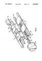
- FIG. 1is a perspective view of an ink jet printing station having a sheet transport system and incorporating an encoder in accordance with the invention
- FIG. 2is a schematic perspective view of the sheet transport system of the printing station shown in FIG. 1;
- FIG. 3is a schematic illustration of a control system for the printing station illustrated in FIG. 1;
- FIG. 4is a schematic plan view of an optical digital disc used for providing control information
- FIG. 5is a schematic illustration of a recording system for recording timing information on an optical digital disc.
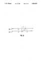
- FIG. 6is a schematic illustration of the recording of timing signals.
- control apparatus and method of the inventionhas broad applicability to encoding systems usable in a wide variety of machines, it has particular applicability to the control of printers.
- the following descriptionis in that context.
- FIG. 1shows an ink jet printing station 10 which includes an ink jet print bar assembly 12.
- the ink jets of the print bar assemblycan be of the thermal or drop on demand type. The construction of such jets is well known and therefore a detailed description of them is not necessary.
- the bar assemblymay include a plurality of closely spaced jets or a traveling printhead for jetting ink onto a printing medium, such as paper sheet S.
- the successive printing position of the ink jet nozzles in the direction of travel of the sheet Sare very closely spaced to attain good image resolution and the operation of the nozzles at each position is controlled by a separate electrical control signal controlling the timing of the firing of the ink jets.
- the sheet Sis carried laterally in the direction of arrow F 1 beneath the print bar assembly 12 by a sheet transport system 14 (hereinafter described in more detail).
- a rotary electrical motor 16drives the transport system 14 in a desired direction.
- a digital optical encoder 18is mounted on and driven by the transport system 14. The encoder 18 provides control signals for controlling the ink jets in the print bar assembly 12 and may also provide control signals for controlling other operations of the printing station or other work stations of the equipment in which the printing station 10 is mounted.
- the transport systemincludes a plurality of rotatable rollers on which one or more endless transport belts 20 are entrained.
- the belts 20are entrained over freely rotatable incoming roll 22 and a first central support roll 24.
- the belts 20are then diverted downwardly toward and pass in contact with the lower circumference of the encoder roller 26 and then pass over a second central support roller 30 to drive roller 32, which is driven by the motor 16.
- the belts 20then pass back beneath the upper rollers to a lower roller 34 and return to the incoming roller 22.
- the rollers 22, 24, 30 and 32are arranged so that the belts 20 form substantially flat portions for supporting the paper sheet S as it passes the print bar assembly 12.
- a support plate(not shown) is provided in the region between rollers 24 and 30 to support sheet S as ink is jetted onto the sheet.
- encoder roller 26is connected by a shaft 28 to the encoder 18.
- shaft 28comprises a rotary mechanical input to the encoder 18.
- the encoder 18comprises a means for storing control information and a reading mechanism for reading such information.
- the encoder 18comprises a compact disc playback unit of the type used for audio compact disc players. Such units are commonly used in personal audio systems and are known and widely available. In these units, a replaceable, digitally encoded optical disc is rotated at a constant linear velocity. A laser read out system is moved radially with respect to the disc to read out digital information recorded on successive spiral tracks on the disc.
- Such compact disc playback unitsincorporate systems for controlling movement of the laser playback assembly and for insuring playback accuracy the digital information encoded on the disc.
- optical digital discsinvolve known technologies and are described, for example in the Electronics Engineers' Handbook, 3rd Edition (1989) pp 19-89 to 19-94, published by McGraw-Hill, Inc. and incorporated herein by reference. Such systems are also disclosed, for example, in U.S. Pat. Nos. 4,366,564 and 4,530,073, which are incorporated herein by reference. Laser readable optical/magneto optical discs having rerecording capabilities are also known and could be utilized for purposes of this invention.
- the conventional audio optical disk playback unitcan be modified to remove the motor which normally drives the disc and, instead, utilize rotation of shaft 28 to rotate the digital disc 40 (FIG. 3).
- the disc 40is driven in a direct one-to-one relationship with the mechanical input to the encoder.
- the shaft 28can be the roller shaft as shown in FIG. 2 or can comprise a central shaft which rotatably supports a transport drum.
- a readout or playback head 41is moved radially to follow at least one spiral track 42 on which information is encoded.
- the outputis a stream of output pulses which correspond to successive incremental positions of the sheet S during its transport.
- nis a whole integer between about 5 to about 10 for belt transport systems, depending upon the relationship between the diameter of the encoder roller and the length of the transport belts.
- nis one when one sheet is fed for each rotation of the drum.
- the control information recorded on the track 42can function as positional information to control, for example, the firing of ink jets in the print bar assembly 12.
- signals from the encoder 18are provided to a control unit 36 which can comprise, for example, a microprocessor.
- the signalsare read from the digital optical disc 40 by a laser read-out assembly 41, which is movable radially with respect to the disc.
- Control arrangements for moving the read-out assemblyare used in digital disc players and such an arrangement is utilized in the present encoder. Therefore, no further details of such systems are necessary.
- the control unit 36controls, for example, the movement and firing of a transversely movable ink jet printing head 38 or the firing of the plurality of fixed ink jets that are mounted in the print bar assembly 12. Because the digital optical disc 40 can store a higher number of control pulses for each revolution of the disc, the disc can be driven directly by parts of the sheet transport system and provide a higher number of control pulses. This avoids the need for any step up system to drive the disc.
- the optical encoder 18is especially useful with drum transports.
- Drum transportsrequire high resolution when used with ink jet printers.
- the digital optical encoder disccan be mounted for rotation with the drum to provide the number of control pulses for ink jet printers. For example, one revolution of the disc 40 can provide on the order of 255,000 control pulses, which, for a typical five inch diameter transport drum, is sufficient to provide positional control pulses for driving an ink jet system having a resolution of 600 dots per inch. Since the disc is fixed to rotate with the drum, very high positional accuracy is assured as each pulse corresponds to an actual discrete physical position of the drum.
- pulse informationis recorded on laser disc 40 in spiral tracks 42 in the form of substantially uniformly spaced pits or magneto optical spots.
- An advantage of the systemis that several 360° tracks of information can be recorded spirally on the disc.
- the gap between successive sheetscan be utilized to provide the time necessary to move the laser read-out assembly 41 through the radial distance 0, from an ending point on an inner portion of the track to a beginning point on an outer portion of the track.
- the number of spiral convolutions of track 42exceeds by at least 1 the number of revolutions of the disc 40 needed to provide the greatest number of position signals required for one transport system cycle. This is desirable so that the reading operation can begin again simply by moving reader 41 radially to the outermost or first track and immediately being reading control pulses in preparation for the next sheet. This avoids the possibility of the reader 41 being positioned at a blank part of the disc when it is moved radially outwardly to begin a new reading cycle. Because only a small number of spiral convolutions on the disc are needed, only a small amount of radial movement of the reader 41 is needed, in comparison to its normal transverse for audio discs.
- an optical digital disc 40which is unique to the particular transport system, is made.
- the shaft 28is utilized to drive the disc during recording, as shown in FIG. 5.
- the transport system, including shaft 28,is driven at its normal operational speed.
- the pulse informationis recorded on the disc by a laser writing head 44 at a predetermined rate, representative of the desired resolution or timing frequency, by signals from a controllable frequency generator 46.
- Systems utilizing laser writing heads for forming pits on optical digital disksare known and commercially available. Such systems, as well as the above mentioned optical/magneto optical systems, can be adapted to utilize the transport drive to rotate the disc during the recording operation.
- FIG. 6The improvement in the resolution of control information is illustrated schematically in FIG. 6.
- the tracks 50 and 52are shown as straight.
- a series of signals q, r and sare shown in idealized fashion; that is, uniformly spaced, as a result of a constant speed of rotation of the disc during recording of a fixed frequency signal.
- the signals q', r' and s' of recorded track 52are formed to reflect variations in speed of the disc. For example, if there is a local increase in the speed of the disc between the formation of signals r' and s', the distance d' will be greater than the idealized difference d, which would occur if the disc is rotated at a constant speed.
- Having the control signal generated at s'ensures that the controlled event, for example, an ink jet firing, occurs at the proper point on the sheet S, irrespective of the timing anomaly between r' and s'.
- An advantage of this inventionis that a high number of control pulses can be provided for each revolution of the digital optical disc, allowing the disc to be driven directly by and at the same speed as the transport system.
- a further advantage of this processis that mechanical anomalies resulting from eccentricities in the rollers or in bearings mounting the rollers, and other mechanical irregularities, will result in those anomalies being imparted to the disc during rotation. This results in the timing information encoded on the disc being recorded in a manner that inherently includes and compensates for such anomalies.
- the control signals provided by the encoder 18more accurately reflect the positional information of the transport system 14, thereby improving printing quality for ink jet printers. Further, such information can be utilized by field personnel to assess the condition of the transport mechanism, for example, as would result from bearing or roller wear.
Landscapes
- Character Spaces And Line Spaces In Printers (AREA)
- Handling Of Sheets (AREA)
- Transmission And Conversion Of Sensor Element Output (AREA)
- Optical Transform (AREA)
- Control Of Position Or Direction (AREA)
Abstract
Description
Claims (18)
Priority Applications (5)
| Application Number | Priority Date | Filing Date | Title |
|---|---|---|---|
| US07/769,290US5241525A (en) | 1991-10-01 | 1991-10-01 | Digital optical disc encoder system |
| CA002078283ACA2078283C (en) | 1991-10-01 | 1992-09-15 | Digital optical disc encoder system |
| JP4252698AJPH05233063A (en) | 1991-10-01 | 1992-09-22 | Machine controller |
| EP92308913AEP0535932B1 (en) | 1991-10-01 | 1992-09-30 | Digital optical disc encoder system |
| DE69216344TDE69216344T2 (en) | 1991-10-01 | 1992-09-30 | Digital image plate coding process |
Applications Claiming Priority (1)
| Application Number | Priority Date | Filing Date | Title |
|---|---|---|---|
| US07/769,290US5241525A (en) | 1991-10-01 | 1991-10-01 | Digital optical disc encoder system |
Publications (1)
| Publication Number | Publication Date |
|---|---|
| US5241525Atrue US5241525A (en) | 1993-08-31 |
Family
ID=25085024
Family Applications (1)
| Application Number | Title | Priority Date | Filing Date |
|---|---|---|---|
| US07/769,290Expired - LifetimeUS5241525A (en) | 1991-10-01 | 1991-10-01 | Digital optical disc encoder system |
Country Status (5)
| Country | Link |
|---|---|
| US (1) | US5241525A (en) |
| EP (1) | EP0535932B1 (en) |
| JP (1) | JPH05233063A (en) |
| CA (1) | CA2078283C (en) |
| DE (1) | DE69216344T2 (en) |
Cited By (16)
| Publication number | Priority date | Publication date | Assignee | Title |
|---|---|---|---|---|
| DE19515139A1 (en)* | 1995-04-25 | 1996-10-31 | Sachse Lothar | Indicating path and/or angular position marked on disc or tape |
| US5634169A (en)* | 1996-02-16 | 1997-05-27 | Lexmark International, Inc. | Multiple function encoder wheel for cartridges utilized in an electrophotographic output device |
| US5995772A (en)* | 1996-02-16 | 1999-11-30 | Lexmark International Inc. | Imaging apparatus cartridge including an encoded device |
| US6009285A (en)* | 1996-02-16 | 1999-12-28 | Lexmark International, Inc. | Method for determining characteristics of an electrophotographic cartridge carrying a rotatable element |
| USD450712S1 (en) | 2000-02-09 | 2001-11-20 | Nimbus Technology & Engineering | Disk mastering apparatus |
| US6371593B1 (en)* | 2001-01-05 | 2002-04-16 | Acer Communication And Multimedia Inc. | Error detection and correction for printer positioning logic |
| US6428224B1 (en) | 1999-12-21 | 2002-08-06 | Lexmark International, Inc. | Error mapping technique for a printer |
| US20020169541A1 (en)* | 1995-01-11 | 2002-11-14 | Bouve W. Lincoln | System and methods for remotely accessing a selected group of items of interest from a database |
| US6609781B2 (en) | 2000-12-13 | 2003-08-26 | Lexmark International, Inc. | Printer system with encoder filtering arrangement and method for high frequency error reduction |
| US6650077B1 (en) | 2001-06-27 | 2003-11-18 | Lexmark International, Inc. | Method for controlling printer paper feed |
| US20040135076A1 (en)* | 2003-01-15 | 2004-07-15 | Xerox Corporation | Method and apparatus for obtaining a high quality sine wave from an analog quadrature encoder |
| US20070126389A1 (en)* | 2005-12-05 | 2007-06-07 | Josef Siraky | Positioning device |
| US20090021557A1 (en)* | 2007-07-19 | 2009-01-22 | Xerox Corporation | Modular encoder |
| US7673876B1 (en) | 2009-02-02 | 2010-03-09 | Xerox Corporation | Velocity matching calibration method for multiple independently driven sheet transport devices |
| US20100301548A1 (en)* | 2009-05-29 | 2010-12-02 | Xerox Corporation | Hybrid control of sheet transport modules |
| US8020864B1 (en) | 2010-05-27 | 2011-09-20 | Xerox Corporation | Printing system and method using alternating velocity and torque control modes for operating one or more select sheet transport devices to avoid contention |
Families Citing this family (5)
| Publication number | Priority date | Publication date | Assignee | Title |
|---|---|---|---|---|
| EP0680829A3 (en)* | 1994-05-03 | 1995-12-27 | Hewlett Packard Co | Optical control system for media handling assemblies in printers. |
| DE4427733C1 (en)* | 1994-08-05 | 1995-10-12 | Ruhlatec Industrieprodukte | Printing roller drive by electronically controlled stepping motor |
| US5986686A (en)* | 1995-05-12 | 1999-11-16 | Gerber Scientific Produccts, Inc. | Apparatus for making graphic products having a platen drive with encoded sprockets |
| US5868507A (en)* | 1997-04-09 | 1999-02-09 | Gerber Scientific Products, Inc. | Plotter having sprockets for driving sheets relative to a tool carriage and a fixed sheet support extending between the sprockets |
| US8336984B2 (en)* | 2010-08-30 | 2012-12-25 | Eastman Kodak Company | Encoder for inkjet printers |
Citations (13)
| Publication number | Priority date | Publication date | Assignee | Title |
|---|---|---|---|---|
| US3949856A (en)* | 1972-11-29 | 1976-04-13 | Siemens Aktiengesellschaft | System to detect abnormal paper feed in printers |
| US3987492A (en)* | 1973-10-01 | 1976-10-19 | Siemens Aktiengesellschaft | Liquid jet recorder |
| US4366564A (en)* | 1980-01-09 | 1982-12-28 | U.S. Philips Corporation | Apparatus for writing digital information in a disc-shaped optically readable record carrier |
| US4445128A (en)* | 1982-04-02 | 1984-04-24 | Pitney Bowes Inc. | Method and apparatus for compensating for irregular motion |
| GB2136733A (en)* | 1983-03-11 | 1984-09-26 | Xerox Corp | Asynchronous printing |
| US4530073A (en)* | 1981-08-25 | 1985-07-16 | Sony Corporation | Disc reproducing apparatus |
| US4544956A (en)* | 1983-03-30 | 1985-10-01 | Tokyo Shibaura Denki Kabushiki | Image information registering/retrieving system |
| US4574291A (en)* | 1984-08-29 | 1986-03-04 | Tektronix, Inc. | Phase locked synchronizer for printer timing control |
| US4584047A (en)* | 1984-04-03 | 1986-04-22 | Monarch Marking Systems, Inc. | Hand-held labeler having improved web position sensing and print head control |
| US4733069A (en)* | 1986-02-14 | 1988-03-22 | Optec Co., Ltd. | Position encoder using a laser scan beam |
| US4843338A (en)* | 1987-10-23 | 1989-06-27 | Hewlett-Packard Company | Ink-set printhead-to-paper referencing system |
| US4956648A (en)* | 1988-07-05 | 1990-09-11 | Seiko Instruments | Dot position discrepancy correcting circuit for printing apparatus |
| US4978971A (en)* | 1989-11-06 | 1990-12-18 | Tektronix, Inc. | Method and apparatus for reformatting print data |
- 1991
- 1991-10-01USUS07/769,290patent/US5241525A/ennot_activeExpired - Lifetime
- 1992
- 1992-09-15CACA002078283Apatent/CA2078283C/ennot_activeExpired - Fee Related
- 1992-09-22JPJP4252698Apatent/JPH05233063A/enactivePending
- 1992-09-30EPEP92308913Apatent/EP0535932B1/ennot_activeExpired - Lifetime
- 1992-09-30DEDE69216344Tpatent/DE69216344T2/ennot_activeExpired - Lifetime
Patent Citations (13)
| Publication number | Priority date | Publication date | Assignee | Title |
|---|---|---|---|---|
| US3949856A (en)* | 1972-11-29 | 1976-04-13 | Siemens Aktiengesellschaft | System to detect abnormal paper feed in printers |
| US3987492A (en)* | 1973-10-01 | 1976-10-19 | Siemens Aktiengesellschaft | Liquid jet recorder |
| US4366564A (en)* | 1980-01-09 | 1982-12-28 | U.S. Philips Corporation | Apparatus for writing digital information in a disc-shaped optically readable record carrier |
| US4530073A (en)* | 1981-08-25 | 1985-07-16 | Sony Corporation | Disc reproducing apparatus |
| US4445128A (en)* | 1982-04-02 | 1984-04-24 | Pitney Bowes Inc. | Method and apparatus for compensating for irregular motion |
| GB2136733A (en)* | 1983-03-11 | 1984-09-26 | Xerox Corp | Asynchronous printing |
| US4544956A (en)* | 1983-03-30 | 1985-10-01 | Tokyo Shibaura Denki Kabushiki | Image information registering/retrieving system |
| US4584047A (en)* | 1984-04-03 | 1986-04-22 | Monarch Marking Systems, Inc. | Hand-held labeler having improved web position sensing and print head control |
| US4574291A (en)* | 1984-08-29 | 1986-03-04 | Tektronix, Inc. | Phase locked synchronizer for printer timing control |
| US4733069A (en)* | 1986-02-14 | 1988-03-22 | Optec Co., Ltd. | Position encoder using a laser scan beam |
| US4843338A (en)* | 1987-10-23 | 1989-06-27 | Hewlett-Packard Company | Ink-set printhead-to-paper referencing system |
| US4956648A (en)* | 1988-07-05 | 1990-09-11 | Seiko Instruments | Dot position discrepancy correcting circuit for printing apparatus |
| US4978971A (en)* | 1989-11-06 | 1990-12-18 | Tektronix, Inc. | Method and apparatus for reformatting print data |
Non-Patent Citations (4)
| Title |
|---|
| Electronic Engineering Times, May 20, 1991, page 1, "Sony Sounds Off About U.S. Mini Disc System", Junko Yoshida and page 94, "Sony Breaks On Throughout To the Other Side", Richard Doherty. |
| Electronic Engineering Times, May 20, 1991, page 1, Sony Sounds Off About U.S. Mini Disc System , Junko Yoshida and page 94, Sony Breaks On Throughout To the Other Side , Richard Doherty.* |
| Electronics Engineers Handbook, 3rd Edition, McGraw Hill Book Co., pp. 19 89 to 19 24.* |
| Electronics Engineers' Handbook, 3rd Edition, McGraw-Hill Book Co., pp. 19-89 to 19-24. |
Cited By (25)
| Publication number | Priority date | Publication date | Assignee | Title |
|---|---|---|---|---|
| US20020169541A1 (en)* | 1995-01-11 | 2002-11-14 | Bouve W. Lincoln | System and methods for remotely accessing a selected group of items of interest from a database |
| DE19515139A1 (en)* | 1995-04-25 | 1996-10-31 | Sachse Lothar | Indicating path and/or angular position marked on disc or tape |
| US5634169A (en)* | 1996-02-16 | 1997-05-27 | Lexmark International, Inc. | Multiple function encoder wheel for cartridges utilized in an electrophotographic output device |
| US5942067A (en)* | 1996-02-16 | 1999-08-24 | Lexmark International, Inc. | Apparatus and method for encoding an encoder wheel |
| US5995772A (en)* | 1996-02-16 | 1999-11-30 | Lexmark International Inc. | Imaging apparatus cartridge including an encoded device |
| US6009285A (en)* | 1996-02-16 | 1999-12-28 | Lexmark International, Inc. | Method for determining characteristics of an electrophotographic cartridge carrying a rotatable element |
| US6169860B1 (en) | 1996-02-16 | 2001-01-02 | Lexmark International, Inc. | Toner cartridge having encoded wheel |
| US6295422B1 (en) | 1996-02-16 | 2001-09-25 | Lexmark International, Inc. | Encoded wheel for a toner cartridge |
| US6397015B2 (en) | 1996-02-16 | 2002-05-28 | Lexmark International, Inc. | Encoded device having positioned indicia for use with a toner cartridge |
| US6428224B1 (en) | 1999-12-21 | 2002-08-06 | Lexmark International, Inc. | Error mapping technique for a printer |
| USD450712S1 (en) | 2000-02-09 | 2001-11-20 | Nimbus Technology & Engineering | Disk mastering apparatus |
| US6609781B2 (en) | 2000-12-13 | 2003-08-26 | Lexmark International, Inc. | Printer system with encoder filtering arrangement and method for high frequency error reduction |
| US6371593B1 (en)* | 2001-01-05 | 2002-04-16 | Acer Communication And Multimedia Inc. | Error detection and correction for printer positioning logic |
| US6650077B1 (en) | 2001-06-27 | 2003-11-18 | Lexmark International, Inc. | Method for controlling printer paper feed |
| US20040135076A1 (en)* | 2003-01-15 | 2004-07-15 | Xerox Corporation | Method and apparatus for obtaining a high quality sine wave from an analog quadrature encoder |
| US20070126389A1 (en)* | 2005-12-05 | 2007-06-07 | Josef Siraky | Positioning device |
| US7638960B2 (en)* | 2005-12-05 | 2009-12-29 | Sick Stegmann Gmbh | Positioning device |
| US8360554B2 (en) | 2007-07-19 | 2013-01-29 | Xerox Corporation | Modular encoder |
| US20090021557A1 (en)* | 2007-07-19 | 2009-01-22 | Xerox Corporation | Modular encoder |
| US7673876B1 (en) | 2009-02-02 | 2010-03-09 | Xerox Corporation | Velocity matching calibration method for multiple independently driven sheet transport devices |
| US7931274B2 (en) | 2009-05-29 | 2011-04-26 | Xerox Corporation | Hybrid control of sheet transport modules |
| US20110133398A1 (en)* | 2009-05-29 | 2011-06-09 | Xerox Corporation | Hybrid control of sheet transport modules |
| US8152166B2 (en) | 2009-05-29 | 2012-04-10 | Xerox Corporation | Hybrid control of sheet transport modules |
| US20100301548A1 (en)* | 2009-05-29 | 2010-12-02 | Xerox Corporation | Hybrid control of sheet transport modules |
| US8020864B1 (en) | 2010-05-27 | 2011-09-20 | Xerox Corporation | Printing system and method using alternating velocity and torque control modes for operating one or more select sheet transport devices to avoid contention |
Also Published As
| Publication number | Publication date |
|---|---|
| DE69216344T2 (en) | 1997-07-03 |
| DE69216344D1 (en) | 1997-02-13 |
| EP0535932A2 (en) | 1993-04-07 |
| EP0535932B1 (en) | 1997-01-02 |
| CA2078283C (en) | 1998-04-21 |
| EP0535932A3 (en) | 1993-04-28 |
| JPH05233063A (en) | 1993-09-10 |
| CA2078283A1 (en) | 1993-04-02 |
Similar Documents
| Publication | Publication Date | Title |
|---|---|---|
| US5241525A (en) | Digital optical disc encoder system | |
| US5452152A (en) | Tracking control on longitudinal azimuth tracks using an auxiliary read head | |
| US4044881A (en) | Serial printer with linear motor drive | |
| US5825378A (en) | Calibration of media advancement to avoid banding in a swath printer | |
| EP0064130B1 (en) | Ribbon feed and take-up mechanism | |
| US5760817A (en) | Laser printer with apparatus to reduce banding by servo adjustment of a scanned laser beam | |
| WO2001020405A1 (en) | Method and apparatus for correcting transfer belt position via stored parameters | |
| US4371904A (en) | Flexible magnetic disk system | |
| CA1078770A (en) | Lateral position control means for data printer heads | |
| US4343012A (en) | Printer control circuit | |
| CN101211637A (en) | Disc drive apparatus and disc printing method | |
| US3735416A (en) | Magnetic printing system | |
| JPH05212924A (en) | Device and method for minimizing scanning error of printer | |
| US4425844A (en) | Home pulse compensation for multiple speed line printer | |
| US4884152A (en) | Method for restoring track 0 | |
| US3750794A (en) | High speed print drum with traveling print hammer | |
| US4235167A (en) | High speed dual pitch impact printer | |
| EP2507066B1 (en) | Method for determining a velocity of an object in a printing system | |
| CN100357112C (en) | Sensing device | |
| US4379302A (en) | Powdered magnetic ink printing devices | |
| US4744683A (en) | Revolving endless bands comprising means for compensating for a displacement perpendicular to their direction of movement | |
| US20060163352A1 (en) | Conveyer | |
| JPS6192874A (en) | Printer carriage position detection mechanism | |
| JP3528073B2 (en) | Sheet transport device for inkjet printer | |
| JP2531814B2 (en) | Servo control system and fixed magnetic disk drive |
Legal Events
| Date | Code | Title | Description |
|---|---|---|---|
| AS | Assignment | Owner name:XEROX CORPORATION A CORPORATION OF NY, CONNECTI Free format text:ASSIGNMENT OF ASSIGNORS INTEREST.;ASSIGNOR:TAYLOR, THOMAS N.;REEL/FRAME:005862/0391 Effective date:19910923 | |
| STCF | Information on status: patent grant | Free format text:PATENTED CASE | |
| FEPP | Fee payment procedure | Free format text:PAYOR NUMBER ASSIGNED (ORIGINAL EVENT CODE: ASPN); ENTITY STATUS OF PATENT OWNER: LARGE ENTITY | |
| FPAY | Fee payment | Year of fee payment:4 | |
| FPAY | Fee payment | Year of fee payment:8 | |
| AS | Assignment | Owner name:BANK ONE, NA, AS ADMINISTRATIVE AGENT, ILLINOIS Free format text:SECURITY INTEREST;ASSIGNOR:XEROX CORPORATION;REEL/FRAME:013153/0001 Effective date:20020621 | |
| AS | Assignment | Owner name:JPMORGAN CHASE BANK, AS COLLATERAL AGENT, TEXAS Free format text:SECURITY AGREEMENT;ASSIGNOR:XEROX CORPORATION;REEL/FRAME:015134/0476 Effective date:20030625 Owner name:JPMORGAN CHASE BANK, AS COLLATERAL AGENT,TEXAS Free format text:SECURITY AGREEMENT;ASSIGNOR:XEROX CORPORATION;REEL/FRAME:015134/0476 Effective date:20030625 | |
| FPAY | Fee payment | Year of fee payment:12 | |
| AS | Assignment | Owner name:XEROX CORPORATION, CONNECTICUT Free format text:RELEASE BY SECURED PARTY;ASSIGNOR:JPMORGAN CHASE BANK, N.A. AS SUCCESSOR-IN-INTEREST ADMINISTRATIVE AGENT AND COLLATERAL AGENT TO JPMORGAN CHASE BANK;REEL/FRAME:066728/0193 Effective date:20220822 |