US5241383A - Pseudo-constant bit rate video coding with quantization parameter adjustment - Google Patents
Pseudo-constant bit rate video coding with quantization parameter adjustmentDownload PDFInfo
- Publication number
- US5241383A US5241383AUS07/882,487US88248792AUS5241383AUS 5241383 AUS5241383 AUS 5241383AUS 88248792 AUS88248792 AUS 88248792AUS 5241383 AUS5241383 AUS 5241383A
- Authority
- US
- United States
- Prior art keywords
- frames
- code bits
- coding
- sgop
- quantizer
- Prior art date
- Legal status (The legal status is an assumption and is not a legal conclusion. Google has not performed a legal analysis and makes no representation as to the accuracy of the status listed.)
- Expired - Lifetime
Links
- 238000013139quantizationMethods0.000titleclaimsabstractdescription46
- 238000000034methodMethods0.000claimsabstractdescription37
- 238000004891communicationMethods0.000claimsabstractdescription14
- 239000011159matrix materialSubstances0.000claimsdescription17
- 230000008859changeEffects0.000abstractdescription3
- 230000015654memoryEffects0.000description19
- 230000006835compressionEffects0.000description13
- 238000007906compressionMethods0.000description13
- 238000012545processingMethods0.000description13
- 239000013598vectorSubstances0.000description12
- 238000011217control strategyMethods0.000description10
- 230000000694effectsEffects0.000description6
- 230000007704transitionEffects0.000description4
- 230000005540biological transmissionEffects0.000description3
- 101150115425Slc27a2 geneProteins0.000description2
- 230000003044adaptive effectEffects0.000description2
- 230000008447perceptionEffects0.000description2
- 238000004088simulationMethods0.000description2
- 238000012360testing methodMethods0.000description2
- 238000003817vacuum liquid chromatographyMethods0.000description2
- 230000000007visual effectEffects0.000description2
- 238000012935AveragingMethods0.000description1
- 238000013459approachMethods0.000description1
- 230000008901benefitEffects0.000description1
- 230000002457bidirectional effectEffects0.000description1
- 230000015556catabolic processEffects0.000description1
- 238000006731degradation reactionMethods0.000description1
- 238000013507mappingMethods0.000description1
- 230000008520organizationEffects0.000description1
- 230000035945sensitivityEffects0.000description1
- 230000002123temporal effectEffects0.000description1
- 230000009466transformationEffects0.000description1
- 230000001960triggered effectEffects0.000description1
Images


Classifications
- H—ELECTRICITY
- H04—ELECTRIC COMMUNICATION TECHNIQUE
- H04N—PICTORIAL COMMUNICATION, e.g. TELEVISION
- H04N19/00—Methods or arrangements for coding, decoding, compressing or decompressing digital video signals
- H04N19/50—Methods or arrangements for coding, decoding, compressing or decompressing digital video signals using predictive coding
- H04N19/503—Methods or arrangements for coding, decoding, compressing or decompressing digital video signals using predictive coding involving temporal prediction
- H04N19/51—Motion estimation or motion compensation
- H04N19/577—Motion compensation with bidirectional frame interpolation, i.e. using B-pictures
- H—ELECTRICITY
- H04—ELECTRIC COMMUNICATION TECHNIQUE
- H04N—PICTORIAL COMMUNICATION, e.g. TELEVISION
- H04N19/00—Methods or arrangements for coding, decoding, compressing or decompressing digital video signals
- H04N19/10—Methods or arrangements for coding, decoding, compressing or decompressing digital video signals using adaptive coding
- H04N19/102—Methods or arrangements for coding, decoding, compressing or decompressing digital video signals using adaptive coding characterised by the element, parameter or selection affected or controlled by the adaptive coding
- H04N19/103—Selection of coding mode or of prediction mode
- H04N19/107—Selection of coding mode or of prediction mode between spatial and temporal predictive coding, e.g. picture refresh
- H—ELECTRICITY
- H04—ELECTRIC COMMUNICATION TECHNIQUE
- H04N—PICTORIAL COMMUNICATION, e.g. TELEVISION
- H04N19/00—Methods or arrangements for coding, decoding, compressing or decompressing digital video signals
- H04N19/10—Methods or arrangements for coding, decoding, compressing or decompressing digital video signals using adaptive coding
- H04N19/102—Methods or arrangements for coding, decoding, compressing or decompressing digital video signals using adaptive coding characterised by the element, parameter or selection affected or controlled by the adaptive coding
- H04N19/124—Quantisation
- H04N19/126—Details of normalisation or weighting functions, e.g. normalisation matrices or variable uniform quantisers
- H—ELECTRICITY
- H04—ELECTRIC COMMUNICATION TECHNIQUE
- H04N—PICTORIAL COMMUNICATION, e.g. TELEVISION
- H04N19/00—Methods or arrangements for coding, decoding, compressing or decompressing digital video signals
- H04N19/10—Methods or arrangements for coding, decoding, compressing or decompressing digital video signals using adaptive coding
- H04N19/134—Methods or arrangements for coding, decoding, compressing or decompressing digital video signals using adaptive coding characterised by the element, parameter or criterion affecting or controlling the adaptive coding
- H04N19/136—Incoming video signal characteristics or properties
- H04N19/137—Motion inside a coding unit, e.g. average field, frame or block difference
- H04N19/139—Analysis of motion vectors, e.g. their magnitude, direction, variance or reliability
- H—ELECTRICITY
- H04—ELECTRIC COMMUNICATION TECHNIQUE
- H04N—PICTORIAL COMMUNICATION, e.g. TELEVISION
- H04N19/00—Methods or arrangements for coding, decoding, compressing or decompressing digital video signals
- H04N19/10—Methods or arrangements for coding, decoding, compressing or decompressing digital video signals using adaptive coding
- H04N19/134—Methods or arrangements for coding, decoding, compressing or decompressing digital video signals using adaptive coding characterised by the element, parameter or criterion affecting or controlling the adaptive coding
- H04N19/146—Data rate or code amount at the encoder output
- H04N19/149—Data rate or code amount at the encoder output by estimating the code amount by means of a model, e.g. mathematical model or statistical model
- H—ELECTRICITY
- H04—ELECTRIC COMMUNICATION TECHNIQUE
- H04N—PICTORIAL COMMUNICATION, e.g. TELEVISION
- H04N19/00—Methods or arrangements for coding, decoding, compressing or decompressing digital video signals
- H04N19/10—Methods or arrangements for coding, decoding, compressing or decompressing digital video signals using adaptive coding
- H04N19/134—Methods or arrangements for coding, decoding, compressing or decompressing digital video signals using adaptive coding characterised by the element, parameter or criterion affecting or controlling the adaptive coding
- H04N19/146—Data rate or code amount at the encoder output
- H04N19/152—Data rate or code amount at the encoder output by measuring the fullness of the transmission buffer
- H—ELECTRICITY
- H04—ELECTRIC COMMUNICATION TECHNIQUE
- H04N—PICTORIAL COMMUNICATION, e.g. TELEVISION
- H04N19/00—Methods or arrangements for coding, decoding, compressing or decompressing digital video signals
- H04N19/10—Methods or arrangements for coding, decoding, compressing or decompressing digital video signals using adaptive coding
- H04N19/169—Methods or arrangements for coding, decoding, compressing or decompressing digital video signals using adaptive coding characterised by the coding unit, i.e. the structural portion or semantic portion of the video signal being the object or the subject of the adaptive coding
- H04N19/17—Methods or arrangements for coding, decoding, compressing or decompressing digital video signals using adaptive coding characterised by the coding unit, i.e. the structural portion or semantic portion of the video signal being the object or the subject of the adaptive coding the unit being an image region, e.g. an object
- H04N19/172—Methods or arrangements for coding, decoding, compressing or decompressing digital video signals using adaptive coding characterised by the coding unit, i.e. the structural portion or semantic portion of the video signal being the object or the subject of the adaptive coding the unit being an image region, e.g. an object the region being a picture, frame or field
- H—ELECTRICITY
- H04—ELECTRIC COMMUNICATION TECHNIQUE
- H04N—PICTORIAL COMMUNICATION, e.g. TELEVISION
- H04N19/00—Methods or arrangements for coding, decoding, compressing or decompressing digital video signals
- H04N19/10—Methods or arrangements for coding, decoding, compressing or decompressing digital video signals using adaptive coding
- H04N19/169—Methods or arrangements for coding, decoding, compressing or decompressing digital video signals using adaptive coding characterised by the coding unit, i.e. the structural portion or semantic portion of the video signal being the object or the subject of the adaptive coding
- H04N19/177—Methods or arrangements for coding, decoding, compressing or decompressing digital video signals using adaptive coding characterised by the coding unit, i.e. the structural portion or semantic portion of the video signal being the object or the subject of the adaptive coding the unit being a group of pictures [GOP]
- H—ELECTRICITY
- H04—ELECTRIC COMMUNICATION TECHNIQUE
- H04N—PICTORIAL COMMUNICATION, e.g. TELEVISION
- H04N19/00—Methods or arrangements for coding, decoding, compressing or decompressing digital video signals
- H04N19/60—Methods or arrangements for coding, decoding, compressing or decompressing digital video signals using transform coding
- H04N19/61—Methods or arrangements for coding, decoding, compressing or decompressing digital video signals using transform coding in combination with predictive coding
- H—ELECTRICITY
- H04—ELECTRIC COMMUNICATION TECHNIQUE
- H04N—PICTORIAL COMMUNICATION, e.g. TELEVISION
- H04N19/00—Methods or arrangements for coding, decoding, compressing or decompressing digital video signals
- H04N19/10—Methods or arrangements for coding, decoding, compressing or decompressing digital video signals using adaptive coding
- H04N19/102—Methods or arrangements for coding, decoding, compressing or decompressing digital video signals using adaptive coding characterised by the element, parameter or selection affected or controlled by the adaptive coding
- H04N19/124—Quantisation
- H—ELECTRICITY
- H04—ELECTRIC COMMUNICATION TECHNIQUE
- H04N—PICTORIAL COMMUNICATION, e.g. TELEVISION
- H04N19/00—Methods or arrangements for coding, decoding, compressing or decompressing digital video signals
- H04N19/10—Methods or arrangements for coding, decoding, compressing or decompressing digital video signals using adaptive coding
- H04N19/134—Methods or arrangements for coding, decoding, compressing or decompressing digital video signals using adaptive coding characterised by the element, parameter or criterion affecting or controlling the adaptive coding
- H04N19/146—Data rate or code amount at the encoder output
Definitions
- the present inventionrelates to a method for coding video signals. More particularly, the present invention relates to a pseudo-constant bit rate video coding algorithm using motion compensated prediction and interpolation and a self governing rate buffer control strategy.
- a video coderis utilized to code a video signal such as an HDTV signal for transmission via a telecommunication channel to a remote location, where the video signal is reconstructed by a decoder.
- a video coderwhich achieves a high compression ratio is utilized.
- Highly compressive video coderstypically employ coding algorithms which utilize three compression modes: intraframe coding, motion compensated predictive coding, and motion compensated interpolative coding.
- the different compression modesare assigned to frames of video as follows.
- a sequence of video framesis divided into groups of N frames called groups of pictures (GOPs).
- the first frame of each GOPis intraframe coded.
- Each group of adjacent predictive and interpolative framesforms a sub-group of pictures (SGOP).
- the number of frames in each SGOPis M and the number of SGOPs in each GOP is L.
- Intra-frame codingrequires no picture information beyond the frame itself.
- the pixels comprising a frame to be intra-frame codedare divided into small blocks such as 8 ⁇ 8 or 16 ⁇ 16 blocks.
- Each blockis coded by a coding circuit which carries out an orthogonal transformation such as a discrete cosine transform (DCT).
- DCTdiscrete cosine transform
- a quantizerthen quantizes the transform coefficients resulting from the orthogonal transform.
- the two other coding modesrequire prediction or interpolation from one or two neighboring frames.
- some method of motion compensationmust be utilized. For each block of pixels in a frame to be predictively coded, the best match block from the nearest previous intra or predictive frame is identified and a corresponding motion vector is obtained. The best match block is used as a motion compensated prediction for the current block. A criterion involving an activity index comparison is used to determine if the current block should be motion compensated. If the test is positive, the current block is coded with a predictive mode, wherein the predictive error (i.e. the difference) between the current block and its motion compensated prediction is DCT coded in conjunction with a quantizer. Otherwise the current block is coded with an intramode, wherein the data in the block is directly DCT transformed and quantized.
- interpolative framesThe processing of interpolative frames is similar, except that an interpolative frame requires bidirectional prediction. Therefore, motion estimation and compensation are performed twice, once with a previous and once with a subsequent intra or predictive frame. Based on a particular criteria, one of the three--forward prediction, backward prediction, or interpolation of both--is selected as the motion compensated prediction. As in predictive frames, either a predictive mode or an intramode is used to code each block depending on a decision criterion involving an activity index.
- the transform coefficients resulting from the DCT transformare quantized.
- the quantizercan be represented by a matrix comprising the elements q(m,n). Each element or parameter q(m,n) represents the quantizer step size for the DCT coefficient having the location (m,n) in transform space.
- the DCT coefficientsare then variable length coded or fixed length coded.
- the number of code bits required to code a framevaries significantly from frame to frame. Interpolative frames require the least number of code bits and intra-frames require the most code bits.
- a rate bufferis utilized as an interface between the coding circuit and the network.
- rate buffer control strategiesare disclosed in the prior art (see, e.g., CCITT SG XV, "Description of Reference Model 8 (RM8),” Doc. 525, June 1989; ISO/MPEG, “MPEG Video Simulation Model 3,” Doc. 90/041, July 1990; W. H. Chen and W. K. Pratt, "Scene Adaptive Coder,” IEEE Trans. Comm., Vol. COM-32, pp. 225-232, Mar. 1984).
- the quantizer step sizesare determined based on the current buffer content without regard for the transitions in video quality caused by changes to the quantizer. This strategy requires an a priori knowledge of a mapping between buffer content and particular quantizer step sizes.
- frames of videoare coded by a coding circuit including a processor for performing an orthogonal transform such as a discrete cosine transform and a quantizer for quantizing the resulting transform coefficients.
- the coding circuitcodes the video frames using an intra-frame coding mode or an interframe coding mode, which may be predictive or interpolative, to generate code bits at a variable rate.
- the code bitsare stored in a rate buffer and transmitted from the rate buffer into a communication channel at a pseudo-constant rate, i.e., a rate which is constant over each frame time interval.
- the quantizer step sizes utilized by the quantizerare periodically adjusted in accordance with a unique adjustment strategy to increase or decrease the number of code bits generated by the coding circuit.
- the rate buffer and quantizer control strategy of the present inventionIn contrast to conventional rate buffer and quantizer control strategies, the rate buffer and quantizer control strategy of the present invention
- the coding method of the present inventioncontrols the rate buffer so that the bit rate transmission into the communication channel is pseudo-constant--i.e., constant over each frame time interval--despite the fluctuations in code bits produced by the coding circuit for the various compression modes.
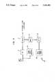
- FIG. 1schematically illustrates a group of video frames known as a GOP and identifies the compression mode--known intra-frame, predictive, or interpolative--used to code each frame.
- FIG. 2schematically illustrates a coding circuit and rate buffer for carrying out the inventive coding algorithm.
- FIG. 3schematically illustrates a circuit which operates on the intraframes.
- FIG. 4schematically illustrates the operation of a quantizer.
- FIG. 5schematically illustrates a coding circuit which operates on the predictive frames.
- FIG. 6schematically illustrates the operation of a coding circuit which operates on the interpolative frames.
- a sequence of frames to be codedis organized into groups referred to as groups of pictures (GOPs).
- groups of picturesOne such group of pictures is illustrated in FIG. 1.
- Each group of picturescomprises N frames.
- N-15so that fifteen frames labeled frame 0,1, . . . ,14 are illustrated.
- the first frame, i.e., frame 0,is coded using an intra-frame coding technique.
- the remainder of the frames in the GOPare interframe coded using a predictive or an interpolative coding technique.
- the number M-1is therefore the number of interpolative frames between predictive frames.
- Each group of adjacent interpolative and predictive framesis named as a sub-group of pictures (SGOP).
- the number of frames in each SGOPis M and the number of SGOPs in each GOP is L.
- an SGOPis identified.
- the frames which are predictively and interpolatively codedare labeled as such.
- frame 0is coded with the intra-frame mode. Because the processing of interpolative frames requires information from the next intra or predictive frame, the frame processing order cannot follow the natural sequence of frame numbering. Thus, following the processing of frame 0, frame 2 is processed with the predictive mode, followed by frame 1 with the interpolative mode, frame 4 with the predictive mode, frame 3 with the interpolative mode and so on (i.e., the order is frame 0, 2, 1, 4, 3, etc.).
- FIG. 2schematically illustrates the operation of a coding circuit 10 for carrying out the inventive coding method.
- Frames to be codedare broken up into blocks of pixels such as 8 ⁇ 8 or 16 ⁇ 16 blocks.
- the blocksare received at the input 12
- the pixel blocksare processed by an intra-frame mode processor 14, a predictive mode processor 16 or interpolative mode processor 18.
- the processors 14, 16, and 18are shown as separate devices in FIG. 2. In reality, the processors 14, 16, and 18 utilize certain elements in common as explained in greater detail below.
- the outputs of the processors 14, 16, and 18are processed by the coder 20 which converts the outputs into variable length or fixed length code words.
- the output of the coder 20is a variable bit rate.
- the bit ratevaries depending on whether intra-frame, predictive or interpolative processing is utilized, with the bit rate being highest for intra-frame processing and lowest for interpolative processing.
- the bit ratealso varies depending on quantization parameters utilized in the intra-frame, predictive and interpolative modes.
- the code words leaving the coder 20are stored in a rate buffer 22 with a variable bit rate.
- the fluctuations in bit rateare smoothed out by the rate buffer 22 which interfaces the variable/fixed length coder 20 with the communication channel 24.
- the rate buffer 22does not output bits to the communication channel 24 at a truly constant bit rate.
- the present inventiondoes achieve a pseudo-constant bit rate, wherein the bits transmitted into the communication channel have a constant bit rate over each frame time interval.
- a feedback techniqueis utilized wherein the content of the buffer 22 controls the quantization parameters utilized in the processors 14, 16, and 18. Specifically, the quantization parameters are adjusted to control the number of code bits generated to maintain the contents of the buffer 22 in a predetermined range.
- the content of the bufferi.e., the fraction of its storage space which is occupied
- a quantizer adjustment processor 26to control the quantization parameters utilized in the intra-frame, predictive, and interpolative coding modes.
- the intra-frame processor 14, predictive mode processor 16, and interpolative mode processor 18are now considered in greater detail.
- the intra-frame coding processor 14is illustrated in FIG. 3.
- a DCT processor 30applies a discrete cosine transform to the input blocks of pixels in two dimensions.
- FIG. 4illustrates the operation of the quantizer 32 for a particular value of (m,n).
- FIG. 4is a graph which plots quantizer input versus quantizer output for a particular value of (m,n).
- the quantizer input F(m,n)is rounded off to a specific quantization level 35 to produce an output F*(m,n).
- the quantization levels 35are separated by the step size q(m,n), with a threshold T being equal to q/2 for intramode coding (for predictive mode coding the threshold T is equal to q).
- the quantized transform coefficients outputted by the quantizer 32are transmitted to the variable/fixed length coder 20 (see FIG. 2). Because decompressed data is needed for future predictive and interpolative frames, the quantized transform coefficients are inverse quantized by the inverse quantizer 34. The inverse quantized transform coefficients are then processed by the inverse DCT processor 36 and the resulting decompressed pixel values are stored in the frame memory 38. The original frame data is also needed for the next predictive and interpolative frames for purposes of motion compensation. Thus, the original frame data is stored in the frame memory 40. The memories 38 and 40 store different data, the memory 38 storing decompressed pixel values and the memory 40 storing original pixel values.
- a processor 16 for performing predictive codingis illustrated in FIG. 5.
- the processor 16 of FIG. 5comprises the DCT processor 30, the quantizer 32, inverse quantizer 34, the inverse DCT processor 36 and the frame memories 38 and 40.
- the first stepis to find the best match from the previous nearest intra-frame or predictive frame within a prechosen searching range. This is carried out by the motion estimation processor 42.
- G(m-v x , n-v y )denote the corresponding block displaced by a motion vector v x ,v y in the previous nearest intra-frame or predictive frame.
- the best match vector v ox ,v oyis obtained by minimizing the displaced block difference (DBD) defined as ##EQU2## over a pre-chosen searching range.
- DBDdisplaced block difference
- G(m,n)is the original data stored in the frame memory 40 and not the decompressed data stored in the frame memory 38. Using the original data for motion estimation gives motion vectors independent of the quantization parameters utilized by the quantizer 32.
- the motion compensated predictive error dF(m,n)is defined as
- G'(m,n)represents the decompressed image stored in the memory 38 corresponding to G(m,n).
- a decision rule based on an activity indexis utilized.
- the decision rulehas been widely adapted in international standards (see, e.g., ISO, MPEG "MPEG Video Simulation Model 3", Document 90/041, July 1990; and CCITT SG XV, "Description of Reference Model 8 (RM8)", Document 525, June 1989).
- the activity index (i.e. variance) of the original block F(m,n)is smaller than the activity index (i.e. power) of dF(m,n)
- intramode codingis utilized and F(m,n) is coded directly since less activity implies fewer code bits, otherwise predictive mode coding is utilized and dF(m,n) is coded.
- pixel values G'(m-v ox ,n-v oy )are transmitted to a mode selector 44.
- the mode selector 44performs the test and outputs the decision at an output 43, which output 43 is connected to a switch 45. If the decision is to code a block using intramode coding, the switch 45 is positioned so that the pixel block is transmitted directly to the DCT processor 30 and quantizer 32.
- the predictive error dF(m,n)is obtained by the subtraction element 47 by subtracting G'(m-v ox ,n-v oy ), which is read out of the frame memory 38, from the input block F(m,n).
- the predictive error dF(m,n)is then coded using the DCT processor 30 and quantizer 32.
- the quantized transform coefficients output by the quantizer 32are transmitted to the variable/fixed length coder 20 (see FIG. 2).
- the remotely located decoderIn order for a remotely located decoder to reconstruct the video image, the remotely located decoder must know the coding mode utilized and the best match motion vector when the predictive coding mode is utilized. Information identifying the mode and best match motion vector is output by the mode selector 44 at outputs 48 and 49.
- the predictively coded framehas to be reconstructed and stored in the frame memory 38 for use in the coding of future predictive and/or interpolative frames. This is accomplished on a block-by-block basis.
- the intramode coded blocksare reconstructed using the inverse quantizer 34 and the inverse DCT processor 36.
- the predictively coded blocksare reconstructed by first reconstructing the error dF(m,n) through use of the inverse quantizer 34 and inverse DCT processor 36.
- the reconstructed error dF'(m,n)is then added with G'(m-v ox ,n-v oy ) using the adder 41 to obtain the reconstructed block F'(m,n) which is stored in the frame memory 38.
- the original blocks F(m,n)are stored in the frame memory 40, also for use by future predictive or interpolative frames.
- a processor 18 for processing interpolative framesis illustrated in FIG. 6.
- the processing of interpolative framesis similar to that of predictive frames.
- the main difference between interpolative coding and predictive codingis that interpolation coding utilizes information from both the previous frame and the next frame to obtain a motion compensated prediction for a block of pixels.
- the interpolative processor 18includes two additional frame memories 38' and 40' for storing the next frame after it has been reconstructed and in its original format, as well as the frame memories 38 and 40 for storing the previous frame after reconstruction and in its original format.
- the processor 18also includes an additional motion estimation processor 42'.
- the two motion estimators 42 and 42'are utilized to obtain best match motion vectors from the previous and next frames, respectively, by minimizing the DBD defined above.
- the next stepis to determine which motion compensation is to be utilized.
- the motion compensation decisionis made as follows:
- DBD minMin ⁇ DBD(v p o ;g p ),DBD(v n o ;g n ),DBD pn ⁇ , ##EQU3## ii. if DBD min is equal to DBD(v p o ;g p ), only v p o is used for computing the motion-compensated predictive error;
- both motion vectors v p o and v n oare used to compute the motion-compensated predictive error.
- the interpolation manipulation unit 60 of FIG. 6insures that appropriate pixel data from the memory 38 and/or 38' is transmitted to the subtraction element 47 when a predictive mode is utilized.
- VLCVoice Call Continuity
- a frame adaptive approachis adopted in designing all VLCs. The VLCs are selected for each frame according to the corresponding symbol statistics with the shortest VLC code words being chosen for the most frequently occurring symbols. Although this introduces code book overhead associated with communicating the meaning of VLC code words to the decoder, this overhead is small in practice and the overall bit rate is lower than when global VLC's are used for all frames.
- the quantizer 32can choose among S quantization matrices Q 0 ,O 1 , . . . , Q S-1 .
- the elements in the i th quantization matrix Qare labeled q i (m,n), where q i (m,n) is the quantizer step size for the transform coefficient located at (m,n) in transform space.
- the elements q iare smaller for smaller i.
- the highest bit rateis achieved when Q 0 is utilized and the lowest bit rate is achieved when Q S-1 is utilized.
- the elements q i (m,n) of the quantization matrices Q iare defined as
- R SGOP and R GOPdenote the desired bit rate for transmission from the rate buffer 22 into the telecommunications channel 24 (see FIG. 2) per SGOP and per GOP respectively.
- the rates R SGOP and R GOPare obtained by multiplying the desired bit rate per frame by the number of frames in each SGOP and GOP respectively.
- the initial buffer contentis zero as measured relative to the lower limit -p 1 B.
- the rate buffer control strategyis described below.
- the processing required to carry out the rate buffer control strategyoccurs at the adjustment processor 26 of FIG. 2.
- the first frame in the current GOPis intra-frame coded using a quantizer matrix determined from the last SGOP in the previous GOP.
- the buffer contentis updated by adding the actual number of coded bits generated by the coding circuit and then subtracting the number of bits transmitted from the rate buffer into the communication channel. If the buffer content reaches an upper limit close to p 2 B, the buffer is in an overflow alert state. The processing for an overflow alert state is described at (5) below.
- INTRABITSis the actual coded bit count from the most recent intra-frame
- Lis the number of SGOPs in each GOP; and H SM is a non-negative integer.
- EB.sub. ⁇is an estimated bit count for the current SGOP so that the buffer can be emptied to zero bits at the end of the next H SM GOPs following the current GOP. (This means that if the estimated bit count EB.sub. ⁇ were to be utilized for each SGOP until the end of H SM GOPs following the current GOP and the desired number of bits is transmitted out of the buffer in each frame interval, the buffer would become empty).
- the integer H SMcontrols the instant when the buffer is expected to be emptied to zero bits.
- H SM0
- EB.sub. ⁇ for small ⁇ and large ⁇may be drastically different. This may cause improper and unnecessary quantizer adjustments.
- the index of the quantizer matrix used to code SGOP.sub. ⁇is i.sub. ⁇ where 0 ⁇ i.sub. ⁇ ⁇ S-1.
- the buffer content B.sub. ⁇is updated by adding the number of actual code bits generated by coding SGOP.sub. ⁇ and then subtracting the bits transmitted into the communication channel. If the buffer content reaches an upper limit close to p 2 B, the buffer is in an overflow state and the processing is in accordance with (5) below.
- a quantization matrix with index i.sub. ⁇is used to code SGOP.sub. ⁇ .
- quantizer matrix indexcan only be incremented or decremented by a maximum of J for each adjustment. Constraining the range of the quantizer index change guarantees a smooth video quality transition. Changing the quantizer index once per SGOP insures that there are no video quality transitions within particular frames.
- the quantization matrix for the first intra-frame and first SGOP of a GOPis chosen based on the EB and SGOPBITS of the last SGOP of the previous GOP.
- the frames following the current frameare not coded until the buffer is emptied to a predetermined lower limit near zero bits. Only trivial header information associated with these frames is sent to the decoder. At the decoder, these frames are accounted for by a repetition of a previous coded frame. After the buffer content is reduced to the desired level, the next frame starts a brand new GOP cycle.
- the quantization matrix indexis set to S-1.
- the video coding scheme of the present inventionis utilized to code CCIR 601 digital video.
- the CCIR 601 digital videocomprises thirty frames per second.
- the frame sizeis 720 pixels/line ⁇ 480 lines/frame for the luminance component (Y) and 360 pixels/line ⁇ 480 lines/frame for the chrominance components (U and V).
- the chrominance componentsmay be preprocessed, using averaging and subsampling, into a lower resolution of 360 elements line ⁇ 240 lines/frame.
- the algorithm of the present inventioncodes studio quality video with a pseudo-constant bit rate of 5 Mbit/sec or higher.
- the block size utilized for codingis 8 ⁇ 8.
- the DCT coefficients, before quantization,are normalized to a maximum possible range of [-5410, 510] given an input range of [-255, 255].
- Some illustrative quantization matricesare ##EQU7##
- p 10.25
- p 20.75.
- a coding circuitincludes a processor for performing an orthogonal transform such as a discrete cosine transform and a quantizer for quantizing the resulting transform coefficients.
- the coding circuitcodes the video frames using an intra-frame, predictive or interpolative coding mode to generate code bits at a variable bit rate.
- the code bitsare stored at a variable rate in a rate buffer, which rate buffer transmits the code bits into a communication channel at a pseudo-constant rate, i.e., a rate which is constant in every time interval of one frame.
- the quantization parameters utilized by the quantizerare periodically adjusted to increase or decrease the amount of code bits generated by the coding circuit.
- the quantization parametersare changed on a global SGOP level to avoid changes of quantization parameters, and corresponding changes in decoded image quality, within particular frames. Constraints are placed on the quantization parameter changes to avoid drastic changes in decoded video image quality.
- the change in quantization parameters for coding the next SGOPis determined by a measure of the deviation between the actual number of coded bits generated by the coding circuit for the previous SGOP and an estimate of the number of code bits for the previous SGOP.
- the estimated number of code bitsis determined based on the contents of the rate buffer such that the rate buffer would be emptied in a predetermined time period.
Landscapes
- Engineering & Computer Science (AREA)
- Multimedia (AREA)
- Signal Processing (AREA)
- Physics & Mathematics (AREA)
- Algebra (AREA)
- General Physics & Mathematics (AREA)
- Mathematical Analysis (AREA)
- Mathematical Optimization (AREA)
- Pure & Applied Mathematics (AREA)
- Compression Or Coding Systems Of Tv Signals (AREA)
Abstract
Description
dF(m,n)=F(m,n)-G'(m-v.sub.ox,n-v.sub.oy)
TABLE 1 ______________________________________ Inter- Symbol Type Intra-frame Predictive polative ______________________________________ DC Transform coefficient VLC FLC FLC AC Transform coefficient VLC VLC VLC Motion Vectors VLC VLC Mode Index FLC VLC ______________________________________
q.sub.i(m,n) =q.sub.0 (m,n)+i[q.sub.S-1 (m,n)-q.sub.0 (m,n)]/S-1
Claims (23)
q.sub.i(m,n) =q.sub.0 (m,n)+i[q.sub.S-1 (m,n)-q.sub.0 (m,n)]/S-1.
Priority Applications (1)
| Application Number | Priority Date | Filing Date | Title |
|---|---|---|---|
| US07/882,487US5241383A (en) | 1992-05-13 | 1992-05-13 | Pseudo-constant bit rate video coding with quantization parameter adjustment |
Applications Claiming Priority (1)
| Application Number | Priority Date | Filing Date | Title |
|---|---|---|---|
| US07/882,487US5241383A (en) | 1992-05-13 | 1992-05-13 | Pseudo-constant bit rate video coding with quantization parameter adjustment |
Publications (1)
| Publication Number | Publication Date |
|---|---|
| US5241383Atrue US5241383A (en) | 1993-08-31 |
Family
ID=25380695
Family Applications (1)
| Application Number | Title | Priority Date | Filing Date |
|---|---|---|---|
| US07/882,487Expired - LifetimeUS5241383A (en) | 1992-05-13 | 1992-05-13 | Pseudo-constant bit rate video coding with quantization parameter adjustment |
Country Status (1)
| Country | Link |
|---|---|
| US (1) | US5241383A (en) |
Cited By (88)
| Publication number | Priority date | Publication date | Assignee | Title |
|---|---|---|---|---|
| US5337153A (en)* | 1991-01-31 | 1994-08-09 | Sony Corporation | Image transforming device for changing frame frequencies of a video image |
| US5361097A (en)* | 1993-04-02 | 1994-11-01 | Rca Thomson Licensing Corporation | Priority processing of encoded video signal including insertion of datastream null words during priority analysis intervals |
| US5414780A (en)* | 1993-01-27 | 1995-05-09 | Immix | Method and apparatus for image data transformation |
| EP0655867A1 (en)* | 1993-11-30 | 1995-05-31 | Koninklijke Philips Electronics N.V. | Device for encoding a video signal |
| US5486862A (en)* | 1991-09-30 | 1996-01-23 | Sony Corporation | Motion picture encoding system |
| US5504529A (en)* | 1991-10-31 | 1996-04-02 | Victor Company Of Japan, Ltd. | Video signal coding apparatus and decoding apparatus |
| EP0661887A3 (en)* | 1993-12-28 | 1996-05-01 | Sharp Kk | Moving image coder. |
| FR2729520A1 (en)* | 1995-01-16 | 1996-07-19 | France Telecom | PROCESS FOR REGULATING THE CODING RATE BY TEMPORAL PREDICTION AND MOTION COMPENSATION, OF A DIGITAL TELEVISION SIGNAL |
| US5543843A (en)* | 1991-07-19 | 1996-08-06 | Sony Corporation | Communication jack nose cleaning tool |
| WO1996026595A1 (en)* | 1995-02-23 | 1996-08-29 | Motorola Inc. | Method and apparatus for preventing overflow and underflow of an encoder buffer in a video compression system |
| WO1996017491A3 (en)* | 1994-12-02 | 1996-08-29 | Philips Electronics Nv | Video editing buffer management |
| WO1996020575A3 (en)* | 1994-12-28 | 1996-09-06 | Philips Electronics Nv | Buffer management in variable bit-rate compression systems |
| US5557419A (en)* | 1993-03-25 | 1996-09-17 | Matsushita Electric Industrial Co., Ltd. | Apparatus for intermittently recording and/or reproducing a time-varying image |
| EP0734173A3 (en)* | 1995-03-24 | 1996-10-09 | Eastman Kodak Company | Fixed rate transmission system with selection of compressor configuration and corresponding method |
| US5602590A (en)* | 1994-07-28 | 1997-02-11 | Nec Corporation | Method for restricting total code volume in data-compression |
| US5603012A (en)* | 1992-06-30 | 1997-02-11 | Discovision Associates | Start code detector |
| US5608458A (en)* | 1994-10-13 | 1997-03-04 | Lucent Technologies Inc. | Method and apparatus for a region-based approach to coding a sequence of video images |
| US5621464A (en)* | 1994-02-03 | 1997-04-15 | Matsushita Electric Industrial Co., Ltd. | Method of reordering a decoded video picture sequence |
| US5625571A (en)* | 1994-03-24 | 1997-04-29 | Discovision Associates | Prediction filter |
| WO1997019562A1 (en)* | 1995-11-21 | 1997-05-29 | Imedia Corporation | Method and apparatus for increasing channel utilization for digital video transmission |
| US5675331A (en)* | 1994-12-14 | 1997-10-07 | Hitachi, Ltd. | Decoding device for decoding a variety of code signals |
| US5677969A (en)* | 1995-02-23 | 1997-10-14 | Motorola, Inc. | Method, rate controller, and system for preventing overflow and underflow of a decoder buffer in a video compression system |
| US5680483A (en)* | 1994-03-02 | 1997-10-21 | U.S. Philips Corporation | Method and device for coding digital signals which are representative of a sequence of pictures |
| US5699544A (en)* | 1993-06-24 | 1997-12-16 | Discovision Associates | Method and apparatus for using a fixed width word for addressing variable width data |
| US5703793A (en)* | 1994-07-29 | 1997-12-30 | Discovision Associates | Video decompression |
| US5721590A (en)* | 1993-11-12 | 1998-02-24 | Nec Corporation | Moving picture decoding control system |
| US5724537A (en)* | 1994-03-24 | 1998-03-03 | Discovision Associates | Interface for connecting a bus to a random access memory using a two wire link |
| US5757434A (en)* | 1993-11-30 | 1998-05-26 | U.S. Philips Corporation | Motion-compensated predictive encoder in which groups of pictures are each encoded with substantially the same number of bits |
| US5757306A (en)* | 1994-08-22 | 1998-05-26 | Nec Corporation | Vector quantization with a control circuit for input and predicted vector quantization |
| US5761741A (en)* | 1994-03-24 | 1998-06-02 | Discovision Associates | Technique for addressing a partial word and concurrently providing a substitution field |
| US5768561A (en) | 1992-06-30 | 1998-06-16 | Discovision Associates | Tokens-based adaptive video processing arrangement |
| US5805914A (en) | 1993-06-24 | 1998-09-08 | Discovision Associates | Data pipeline system and data encoding method |
| US5809270A (en) | 1992-06-30 | 1998-09-15 | Discovision Associates | Inverse quantizer |
| US5822004A (en)* | 1994-06-22 | 1998-10-13 | Thomson Multimedia S.A. | Adaptive quantification based on actual and predicted image data amounts |
| US5835740A (en) | 1992-06-30 | 1998-11-10 | Discovision Associates | Data pipeline system and data encoding method |
| US5847765A (en)* | 1993-11-12 | 1998-12-08 | Nec Corporation | Moving picture decoding control system |
| US5862140A (en)* | 1995-11-21 | 1999-01-19 | Imedia Corporation | Method and apparatus for multiplexing video programs for improved channel utilization |
| US5861894A (en) | 1993-06-24 | 1999-01-19 | Discovision Associates | Buffer manager |
| EP0766479A3 (en)* | 1995-09-29 | 1999-02-03 | Mitsubishi Denki Kabushiki Kaisha | Coding device and decoding device of digital image signal |
| WO1999007158A3 (en)* | 1997-07-29 | 1999-04-22 | Koninkl Philips Electronics Nv | Variable bitrate video coding method and corresponding video coder |
| US5907692A (en) | 1992-06-30 | 1999-05-25 | Discovision Associates | Data pipeline system and data encoding method |
| US5913031A (en)* | 1994-12-02 | 1999-06-15 | U.S. Philips Corporation | Encoder system level buffer management |
| US5937100A (en)* | 1996-02-29 | 1999-08-10 | Ricoh Company, Ltd. | Two-pass image processing method and apparatus using virtual estimation for compressed file size |
| EP0771120A3 (en)* | 1995-10-27 | 1999-09-08 | Kabushiki Kaisha Toshiba | Video encoding and decoding apparatus |
| US5956088A (en)* | 1995-11-21 | 1999-09-21 | Imedia Corporation | Method and apparatus for modifying encoded digital video for improved channel utilization |
| US5963673A (en)* | 1995-12-20 | 1999-10-05 | Sanyo Electric Co., Ltd. | Method and apparatus for adaptively selecting a coding mode for video encoding |
| US5982437A (en)* | 1992-10-26 | 1999-11-09 | Sony Corporation | Coding method and system, and decoding method and system |
| US6018354A (en) | 1994-03-24 | 2000-01-25 | Discovision Associates | Method for accessing banks of DRAM |
| US6018776A (en) | 1992-06-30 | 2000-01-25 | Discovision Associates | System for microprogrammable state machine in video parser clearing and resetting processing stages responsive to flush token generating by token generator responsive to received data |
| US6067417A (en) | 1992-06-30 | 2000-05-23 | Discovision Associates | Picture start token |
| US6079009A (en) | 1992-06-30 | 2000-06-20 | Discovision Associates | Coding standard token in a system compromising a plurality of pipeline stages |
| WO2000041314A1 (en)* | 1998-12-31 | 2000-07-13 | Samsung Electronics Co., Ltd. | Quantization method for iterative decoder in communication system |
| US6112017A (en) | 1992-06-30 | 2000-08-29 | Discovision Associates | Pipeline processing machine having a plurality of reconfigurable processing stages interconnected by a two-wire interface bus |
| US6173069B1 (en) | 1998-01-09 | 2001-01-09 | Sharp Laboratories Of America, Inc. | Method for adapting quantization in video coding using face detection and visual eccentricity weighting |
| US6278735B1 (en) | 1998-03-19 | 2001-08-21 | International Business Machines Corporation | Real-time single pass variable bit rate control strategy and encoder |
| US6285793B1 (en)* | 1995-11-06 | 2001-09-04 | Siemens Medical Systems, Inc. | Method and apparatus for automatically determining a quantization factor value that produces a desired average compression ratio of an image sequence using JPEG compression |
| US6317518B1 (en)* | 1994-04-28 | 2001-11-13 | Canon Kabushiki Kaisha | Image coding apparatus |
| US6326999B1 (en) | 1994-08-23 | 2001-12-04 | Discovision Associates | Data rate conversion |
| US6330665B1 (en) | 1992-06-30 | 2001-12-11 | Discovision Associates | Video parser |
| US6345121B1 (en)* | 1996-11-07 | 2002-02-05 | Matsushita Electric Industrial Co., Ltd. | Image encoding apparatus and an image decoding apparatus |
| US6347094B1 (en)* | 1998-07-21 | 2002-02-12 | Microsoft Corporation | Data rate smoothing |
| EP1189451A1 (en)* | 2000-09-13 | 2002-03-20 | Kabushiki Kaisha Toshiba | Digital video encoder |
| US20020034246A1 (en)* | 2000-08-04 | 2002-03-21 | Kohji Yamada | Method and apparatus for image signal encoding |
| US6366704B1 (en) | 1997-12-01 | 2002-04-02 | Sharp Laboratories Of America, Inc. | Method and apparatus for a delay-adaptive rate control scheme for the frame layer |
| US6385345B1 (en) | 1998-03-31 | 2002-05-07 | Sharp Laboratories Of America, Inc. | Method and apparatus for selecting image data to skip when encoding digital video |
| US20020095681A1 (en)* | 2001-01-16 | 2002-07-18 | Freddie Lin | Uncompressed IP multimedia data transmission and switching |
| US20030007559A1 (en)* | 2000-07-19 | 2003-01-09 | Arthur Lallet | Apparatus and method for image transmission |
| US20030072370A1 (en)* | 1996-11-27 | 2003-04-17 | Realnetworks, Inc. | Method and apparatus for providing scalable pre-compressed digital video with reduced quantization based artifacts (continuation) |
| RU2214680C2 (en)* | 1998-12-31 | 2003-10-20 | Самсунг Электроникс Ко., Лтд. | Method of normalization of value of metric of component decoder in mobile communication system and facility for its implementation |
| RU2216857C2 (en)* | 1997-08-07 | 2003-11-20 | Квэлкомм Инкорпорейтед | Method and device for predictive circuit-delay parametric control |
| US6834080B1 (en) | 2000-09-05 | 2004-12-21 | Kabushiki Kaisha Toshiba | Video encoding method and video encoding apparatus |
| US20050084010A1 (en)* | 2001-12-28 | 2005-04-21 | Koninklijke Philips Electronics N.V. | Video encoding method |
| US20060153290A1 (en)* | 2003-02-04 | 2006-07-13 | Akihiro Watabe | Code conversion method and device thereof |
| US20060177142A1 (en)* | 2005-02-08 | 2006-08-10 | Minhua Zhou | H.264 quantization |
| US7095783B1 (en) | 1992-06-30 | 2006-08-22 | Discovision Associates | Multistandard video decoder and decompression system for processing encoded bit streams including start codes and methods relating thereto |
| US20070027646A1 (en)* | 2005-08-01 | 2007-02-01 | Urmanov Aleksey M | Reducing uncertainty in severely quantized telemetry signals |
| US20070147512A1 (en)* | 2000-04-18 | 2007-06-28 | Ati International Srl | Method and apparatus for rate control for constant-bit-rate-finite-buffer-size video encoder |
| US7418037B1 (en) | 2002-07-15 | 2008-08-26 | Apple Inc. | Method of performing rate control for a compression system |
| EP1665133A4 (en)* | 2004-01-20 | 2009-05-13 | Panasonic Corp | IMAGE ENCODING METHOD, IMAGE DECODING METHOD, IMAGE ENCODING APPARATUS, IMAGE DECODING APPARATUS, AND CORRESPONDING PROGRAM |
| US7769084B1 (en) | 2002-07-15 | 2010-08-03 | Apple Inc. | Method for implementing a quantizer in a multimedia compression and encoding system |
| US7804897B1 (en)* | 2002-12-16 | 2010-09-28 | Apple Inc. | Method for implementing an improved quantizer in a multimedia compression and encoding system |
| US7940843B1 (en) | 2002-12-16 | 2011-05-10 | Apple Inc. | Method of implementing improved rate control for a multimedia compression and encoding system |
| US20110123108A1 (en)* | 2003-07-18 | 2011-05-26 | Sony Corporation | Image encoding apparatus and method for handling intra-image predictive encoding with various color spaces and color signal resolutions |
| US20140188489A1 (en)* | 2001-06-29 | 2014-07-03 | Agere Systems Llc | Method and Apparatus for Frame-Based Buffer Control in a Communication System |
| US20140316788A1 (en)* | 2001-12-14 | 2014-10-23 | Microsoft Corporation | Quality improvement techniques in an audio encoder |
| US9349376B2 (en) | 2007-06-29 | 2016-05-24 | Microsoft Technology Licensing, Llc | Bitstream syntax for multi-process audio decoding |
| WO2017155786A1 (en)* | 2016-03-09 | 2017-09-14 | Sony Corporation | System and method for video processing based on quantization parameter |
| US10663991B2 (en) | 2015-11-12 | 2020-05-26 | Oracle International Corporation | Determining parameters of air-cooling mechanisms |
Citations (3)
| Publication number | Priority date | Publication date | Assignee | Title |
|---|---|---|---|---|
| US5038209A (en)* | 1990-09-27 | 1991-08-06 | At&T Bell Laboratories | Adaptive buffer/quantizer control for transform video coders |
| US5134476A (en)* | 1990-03-30 | 1992-07-28 | At&T Bell Laboratories | Video signal encoding with bit rate control |
| US5144425A (en)* | 1991-08-26 | 1992-09-01 | General Electric Company | Apparatus for hierarchically dividing video signals |
- 1992
- 1992-05-13USUS07/882,487patent/US5241383A/ennot_activeExpired - Lifetime
Patent Citations (3)
| Publication number | Priority date | Publication date | Assignee | Title |
|---|---|---|---|---|
| US5134476A (en)* | 1990-03-30 | 1992-07-28 | At&T Bell Laboratories | Video signal encoding with bit rate control |
| US5038209A (en)* | 1990-09-27 | 1991-08-06 | At&T Bell Laboratories | Adaptive buffer/quantizer control for transform video coders |
| US5144425A (en)* | 1991-08-26 | 1992-09-01 | General Electric Company | Apparatus for hierarchically dividing video signals |
Non-Patent Citations (4)
| Title |
|---|
| "Scene Adaptive Coder," W-H Chen et al., IEEE Trans. Comm., vol. Com-32, No. 3, pp. 225-232, Mar. 1984. |
| Description of Reference Model 8 (RM8), CCITT SGXV, Doc. 525, Working Party XV/4 Specialists Group on Coding for Visual Telephony, Jun. 1989.* |
| MPEG Video Simulation Model 3, ISO/MPEG, Doc. 90/041, International Organization For Standardization, Jul. 1990.* |
| Scene Adaptive Coder, W H Chen et al., IEEE Trans. Comm., vol. Com 32, No. 3, pp. 225 232, Mar. 1984.* |
Cited By (183)
| Publication number | Priority date | Publication date | Assignee | Title |
|---|---|---|---|---|
| US5881301A (en) | 1924-06-30 | 1999-03-09 | Discovision Associates | Inverse modeller |
| US5337153A (en)* | 1991-01-31 | 1994-08-09 | Sony Corporation | Image transforming device for changing frame frequencies of a video image |
| US5543843A (en)* | 1991-07-19 | 1996-08-06 | Sony Corporation | Communication jack nose cleaning tool |
| US5543846A (en)* | 1991-09-30 | 1996-08-06 | Sony Corporation | Motion picture encoding system |
| US5570133A (en)* | 1991-09-30 | 1996-10-29 | Sony Corporation | Motion picture encoding system wherein image quality is maximized using inter-frame and intra-frame encoding |
| US5486862A (en)* | 1991-09-30 | 1996-01-23 | Sony Corporation | Motion picture encoding system |
| US5818534A (en)* | 1991-10-31 | 1998-10-06 | Victor Company Of Japan, Ltd. | Video signal interframe predictive coding apparatus using motion detection |
| US5592229A (en)* | 1991-10-31 | 1997-01-07 | Victor Company Of Japan, Ltd. | Video signal interframe predictive coding apparatus using motion detection |
| US5504529A (en)* | 1991-10-31 | 1996-04-02 | Victor Company Of Japan, Ltd. | Video signal coding apparatus and decoding apparatus |
| US6047112A (en) | 1992-06-30 | 2000-04-04 | Discovision Associates | Technique for initiating processing of a data stream of encoded video information |
| US5907692A (en) | 1992-06-30 | 1999-05-25 | Discovision Associates | Data pipeline system and data encoding method |
| US20030182544A1 (en)* | 1992-06-30 | 2003-09-25 | Wise Adrian P. | Multistandard video decoder and decompression system for processing encoded bit streams including a decoder with token generator and methods relating thereto |
| US6330666B1 (en) | 1992-06-30 | 2001-12-11 | Discovision Associates | Multistandard video decoder and decompression system for processing encoded bit streams including start codes and methods relating thereto |
| US7230986B2 (en) | 1992-06-30 | 2007-06-12 | Discovision Associates | Multistandard video decoder and decompression system for processing encoded bit streams including a video formatter and methods relating thereto |
| US6697930B2 (en) | 1992-06-30 | 2004-02-24 | Discovision Associates | Multistandard video decoder and decompression method for processing encoded bit streams according to respective different standards |
| US5835740A (en) | 1992-06-30 | 1998-11-10 | Discovision Associates | Data pipeline system and data encoding method |
| US6263422B1 (en) | 1992-06-30 | 2001-07-17 | Discovision Associates | Pipeline processing machine with interactive stages operable in response to tokens and system and methods relating thereto |
| US5828907A (en) | 1992-06-30 | 1998-10-27 | Discovision Associates | Token-based adaptive video processing arrangement |
| US7095783B1 (en) | 1992-06-30 | 2006-08-22 | Discovision Associates | Multistandard video decoder and decompression system for processing encoded bit streams including start codes and methods relating thereto |
| US6330665B1 (en) | 1992-06-30 | 2001-12-11 | Discovision Associates | Video parser |
| US5603012A (en)* | 1992-06-30 | 1997-02-11 | Discovision Associates | Start code detector |
| US6122726A (en) | 1992-06-30 | 2000-09-19 | Discovision Associates | Data pipeline system and data encoding method |
| US6112017A (en) | 1992-06-30 | 2000-08-29 | Discovision Associates | Pipeline processing machine having a plurality of reconfigurable processing stages interconnected by a two-wire interface bus |
| US6435737B1 (en) | 1992-06-30 | 2002-08-20 | Discovision Associates | Data pipeline system and data encoding method |
| US6892296B2 (en) | 1992-06-30 | 2005-05-10 | Discovision Associates | Multistandard video decoder and decompression system for processing encoded bit streams including a standard-independent stage and methods relating thereto |
| US7711938B2 (en) | 1992-06-30 | 2010-05-04 | Adrian P Wise | Multistandard video decoder and decompression system for processing encoded bit streams including start code detection and methods relating thereto |
| US6079009A (en) | 1992-06-30 | 2000-06-20 | Discovision Associates | Coding standard token in a system compromising a plurality of pipeline stages |
| US6067417A (en) | 1992-06-30 | 2000-05-23 | Discovision Associates | Picture start token |
| US7149811B2 (en) | 1992-06-30 | 2006-12-12 | Discovision Associates | Multistandard video decoder and decompression system for processing encoded bit streams including a reconfigurable processing stage and methods relating thereto |
| US6038380A (en) | 1992-06-30 | 2000-03-14 | Discovision Associates | Data pipeline system and data encoding method |
| US5809270A (en) | 1992-06-30 | 1998-09-15 | Discovision Associates | Inverse quantizer |
| US6035126A (en) | 1992-06-30 | 2000-03-07 | Discovision Associates | Data pipeline system and data encoding method |
| US6950930B2 (en) | 1992-06-30 | 2005-09-27 | Discovision Associates | Multistandard video decoder and decompression system for processing encoded bit streams including pipeline processing and methods relating thereto |
| US6018776A (en) | 1992-06-30 | 2000-01-25 | Discovision Associates | System for microprogrammable state machine in video parser clearing and resetting processing stages responsive to flush token generating by token generator responsive to received data |
| US5956519A (en) | 1992-06-30 | 1999-09-21 | Discovision Associates | Picture end token in a system comprising a plurality of pipeline stages |
| US5784631A (en) | 1992-06-30 | 1998-07-21 | Discovision Associates | Huffman decoder |
| US5978592A (en) | 1992-06-30 | 1999-11-02 | Discovision Associates | Video decompression and decoding system utilizing control and data tokens |
| US6910125B2 (en) | 1992-06-30 | 2005-06-21 | Discovision Associates | Multistandard video decoder and decompression system for processing encoded bit streams including a decoder with token generator and methods relating thereto |
| US5768561A (en) | 1992-06-30 | 1998-06-16 | Discovision Associates | Tokens-based adaptive video processing arrangement |
| US5982437A (en)* | 1992-10-26 | 1999-11-09 | Sony Corporation | Coding method and system, and decoding method and system |
| US5414780A (en)* | 1993-01-27 | 1995-05-09 | Immix | Method and apparatus for image data transformation |
| US5557419A (en)* | 1993-03-25 | 1996-09-17 | Matsushita Electric Industrial Co., Ltd. | Apparatus for intermittently recording and/or reproducing a time-varying image |
| US5361097A (en)* | 1993-04-02 | 1994-11-01 | Rca Thomson Licensing Corporation | Priority processing of encoded video signal including insertion of datastream null words during priority analysis intervals |
| US5835792A (en) | 1993-06-24 | 1998-11-10 | Discovision Associates | Token-based adaptive video processing arrangement |
| US5861894A (en) | 1993-06-24 | 1999-01-19 | Discovision Associates | Buffer manager |
| US5805914A (en) | 1993-06-24 | 1998-09-08 | Discovision Associates | Data pipeline system and data encoding method |
| US6799246B1 (en) | 1993-06-24 | 2004-09-28 | Discovision Associates | Memory interface for reading/writing data from/to a memory |
| US5699544A (en)* | 1993-06-24 | 1997-12-16 | Discovision Associates | Method and apparatus for using a fixed width word for addressing variable width data |
| US5878273A (en) | 1993-06-24 | 1999-03-02 | Discovision Associates | System for microprogrammable state machine in video parser disabling portion of processing stages responsive to sequence-- end token generating by token generator responsive to received data |
| US5829007A (en)* | 1993-06-24 | 1998-10-27 | Discovision Associates | Technique for implementing a swing buffer in a memory array |
| US5768629A (en) | 1993-06-24 | 1998-06-16 | Discovision Associates | Token-based adaptive video processing arrangement |
| US5721590A (en)* | 1993-11-12 | 1998-02-24 | Nec Corporation | Moving picture decoding control system |
| US5847765A (en)* | 1993-11-12 | 1998-12-08 | Nec Corporation | Moving picture decoding control system |
| EP0655867A1 (en)* | 1993-11-30 | 1995-05-31 | Koninklijke Philips Electronics N.V. | Device for encoding a video signal |
| US5757434A (en)* | 1993-11-30 | 1998-05-26 | U.S. Philips Corporation | Motion-compensated predictive encoder in which groups of pictures are each encoded with substantially the same number of bits |
| BE1007807A3 (en)* | 1993-11-30 | 1995-10-24 | Philips Electronics Nv | Apparatus for encoding a video signal. |
| EP0661887A3 (en)* | 1993-12-28 | 1996-05-01 | Sharp Kk | Moving image coder. |
| US5856848A (en)* | 1993-12-28 | 1999-01-05 | Sharp Kabushiki Kaisha | Moving image coder |
| US5621464A (en)* | 1994-02-03 | 1997-04-15 | Matsushita Electric Industrial Co., Ltd. | Method of reordering a decoded video picture sequence |
| US5680483A (en)* | 1994-03-02 | 1997-10-21 | U.S. Philips Corporation | Method and device for coding digital signals which are representative of a sequence of pictures |
| US5761741A (en)* | 1994-03-24 | 1998-06-02 | Discovision Associates | Technique for addressing a partial word and concurrently providing a substitution field |
| US5625571A (en)* | 1994-03-24 | 1997-04-29 | Discovision Associates | Prediction filter |
| US5689313A (en)* | 1994-03-24 | 1997-11-18 | Discovision Associates | Buffer management in an image formatter |
| US5956741A (en) | 1994-03-24 | 1999-09-21 | Discovision Associates | Interface for connecting a bus to a random access memory using a swing buffer and a buffer manager |
| US5724537A (en)* | 1994-03-24 | 1998-03-03 | Discovision Associates | Interface for connecting a bus to a random access memory using a two wire link |
| US6018354A (en) | 1994-03-24 | 2000-01-25 | Discovision Associates | Method for accessing banks of DRAM |
| US6317518B1 (en)* | 1994-04-28 | 2001-11-13 | Canon Kabushiki Kaisha | Image coding apparatus |
| US5822004A (en)* | 1994-06-22 | 1998-10-13 | Thomson Multimedia S.A. | Adaptive quantification based on actual and predicted image data amounts |
| US5602590A (en)* | 1994-07-28 | 1997-02-11 | Nec Corporation | Method for restricting total code volume in data-compression |
| US5703793A (en)* | 1994-07-29 | 1997-12-30 | Discovision Associates | Video decompression |
| US5801973A (en)* | 1994-07-29 | 1998-09-01 | Discovision Associates | Video decompression |
| US5740460A (en) | 1994-07-29 | 1998-04-14 | Discovision Associates | Arrangement for processing packetized data |
| US5984512A (en) | 1994-07-29 | 1999-11-16 | Discovision Associates | Method for storing video information |
| US5995727A (en) | 1994-07-29 | 1999-11-30 | Discovision Associates | Video decompression |
| US5798719A (en)* | 1994-07-29 | 1998-08-25 | Discovision Associates | Parallel Huffman decoder |
| US5821885A (en)* | 1994-07-29 | 1998-10-13 | Discovision Associates | Video decompression |
| US6217234B1 (en) | 1994-07-29 | 2001-04-17 | Discovision Associates | Apparatus and method for processing data with an arithmetic unit |
| US5757306A (en)* | 1994-08-22 | 1998-05-26 | Nec Corporation | Vector quantization with a control circuit for input and predicted vector quantization |
| US6326999B1 (en) | 1994-08-23 | 2001-12-04 | Discovision Associates | Data rate conversion |
| US5608458A (en)* | 1994-10-13 | 1997-03-04 | Lucent Technologies Inc. | Method and apparatus for a region-based approach to coding a sequence of video images |
| US5913031A (en)* | 1994-12-02 | 1999-06-15 | U.S. Philips Corporation | Encoder system level buffer management |
| US5949487A (en)* | 1994-12-02 | 1999-09-07 | U.S. Philips Corporation | Video editing buffer management |
| WO1996017491A3 (en)* | 1994-12-02 | 1996-08-29 | Philips Electronics Nv | Video editing buffer management |
| CN1110966C (en)* | 1994-12-02 | 2003-06-04 | 皇家菲利浦电子有限公司 | Method for encoding digital video signal and digital video signal encoding device |
| US5675331A (en)* | 1994-12-14 | 1997-10-07 | Hitachi, Ltd. | Decoding device for decoding a variety of code signals |
| WO1996020575A3 (en)* | 1994-12-28 | 1996-09-06 | Philips Electronics Nv | Buffer management in variable bit-rate compression systems |
| US6944221B1 (en)* | 1994-12-28 | 2005-09-13 | Koninklijke Philips Electronics N.V. | Buffer management in variable bit-rate compression systems |
| CN1115055C (en)* | 1994-12-28 | 2003-07-16 | 皇家菲利浦电子有限公司 | Buffer management in variable Bit-rate compression systems |
| FR2729520A1 (en)* | 1995-01-16 | 1996-07-19 | France Telecom | PROCESS FOR REGULATING THE CODING RATE BY TEMPORAL PREDICTION AND MOTION COMPENSATION, OF A DIGITAL TELEVISION SIGNAL |
| WO1996022657A1 (en)* | 1995-01-16 | 1996-07-25 | France Telecom | Digital television signal coding rate regulation method using time prediction and motion compensation |
| US5677969A (en)* | 1995-02-23 | 1997-10-14 | Motorola, Inc. | Method, rate controller, and system for preventing overflow and underflow of a decoder buffer in a video compression system |
| US5619341A (en)* | 1995-02-23 | 1997-04-08 | Motorola, Inc. | Method and apparatus for preventing overflow and underflow of an encoder buffer in a video compression system |
| WO1996026595A1 (en)* | 1995-02-23 | 1996-08-29 | Motorola Inc. | Method and apparatus for preventing overflow and underflow of an encoder buffer in a video compression system |
| EP0734173A3 (en)* | 1995-03-24 | 1996-10-09 | Eastman Kodak Company | Fixed rate transmission system with selection of compressor configuration and corresponding method |
| EP0766479A3 (en)* | 1995-09-29 | 1999-02-03 | Mitsubishi Denki Kabushiki Kaisha | Coding device and decoding device of digital image signal |
| EP0771120A3 (en)* | 1995-10-27 | 1999-09-08 | Kabushiki Kaisha Toshiba | Video encoding and decoding apparatus |
| US6002802A (en)* | 1995-10-27 | 1999-12-14 | Kabushiki Kaisha Toshiba | Video encoding and decoding apparatus |
| US6188792B1 (en) | 1995-10-27 | 2001-02-13 | Kabushiki Kaisha Toshiba | Video encoding and decoding apparatus |
| US6285793B1 (en)* | 1995-11-06 | 2001-09-04 | Siemens Medical Systems, Inc. | Method and apparatus for automatically determining a quantization factor value that produces a desired average compression ratio of an image sequence using JPEG compression |
| WO1997019562A1 (en)* | 1995-11-21 | 1997-05-29 | Imedia Corporation | Method and apparatus for increasing channel utilization for digital video transmission |
| US5877812A (en)* | 1995-11-21 | 1999-03-02 | Imedia Corporation | Method and apparatus for increasing channel utilization for digital video transmission |
| US5956088A (en)* | 1995-11-21 | 1999-09-21 | Imedia Corporation | Method and apparatus for modifying encoded digital video for improved channel utilization |
| US5862140A (en)* | 1995-11-21 | 1999-01-19 | Imedia Corporation | Method and apparatus for multiplexing video programs for improved channel utilization |
| US5963673A (en)* | 1995-12-20 | 1999-10-05 | Sanyo Electric Co., Ltd. | Method and apparatus for adaptively selecting a coding mode for video encoding |
| US5937100A (en)* | 1996-02-29 | 1999-08-10 | Ricoh Company, Ltd. | Two-pass image processing method and apparatus using virtual estimation for compressed file size |
| US6658152B2 (en) | 1996-11-07 | 2003-12-02 | Matsushita Electric Industrial Co., Ltd. | Image coding apparatus and an image decoding apparatus |
| US6697527B2 (en) | 1996-11-07 | 2004-02-24 | Matsushita Electric Industrial Co., Ltd. | Coding method and coding apparatus |
| US6798916B2 (en) | 1996-11-07 | 2004-09-28 | Matsushita Electric Industrial Co., Ltd. | Decoding method and decoding apparatus |
| US6560363B2 (en) | 1996-11-07 | 2003-05-06 | Matsushita Electric Industrial Co., Ltd. | Image coding method and an image coding apparatus |
| US6567555B2 (en) | 1996-11-07 | 2003-05-20 | Matsushita Electric Industrial Co., Ltd. | Decoding method and decoding apparatus |
| US6681048B2 (en) | 1996-11-07 | 2004-01-20 | Matsushita Electric Industrial Co., Ltd. | Image coding apparatus and an image decoding apparatus |
| US6345121B1 (en)* | 1996-11-07 | 2002-02-05 | Matsushita Electric Industrial Co., Ltd. | Image encoding apparatus and an image decoding apparatus |
| US6608939B2 (en) | 1996-11-07 | 2003-08-19 | Matsushita Electric Industrial Co., Ltd. | Image encoder |
| US20030072370A1 (en)* | 1996-11-27 | 2003-04-17 | Realnetworks, Inc. | Method and apparatus for providing scalable pre-compressed digital video with reduced quantization based artifacts (continuation) |
| US7075986B2 (en)* | 1996-11-27 | 2006-07-11 | Realnetworks, Inc. | Method and apparatus for providing scalable pre-compressed digital video with reduced quantization based artifacts |
| WO1999007158A3 (en)* | 1997-07-29 | 1999-04-22 | Koninkl Philips Electronics Nv | Variable bitrate video coding method and corresponding video coder |
| RU2216857C2 (en)* | 1997-08-07 | 2003-11-20 | Квэлкомм Инкорпорейтед | Method and device for predictive circuit-delay parametric control |
| US6366704B1 (en) | 1997-12-01 | 2002-04-02 | Sharp Laboratories Of America, Inc. | Method and apparatus for a delay-adaptive rate control scheme for the frame layer |
| US6173069B1 (en) | 1998-01-09 | 2001-01-09 | Sharp Laboratories Of America, Inc. | Method for adapting quantization in video coding using face detection and visual eccentricity weighting |
| US7181050B1 (en) | 1998-01-09 | 2007-02-20 | Sharp Laboratories Of America, Inc. | Method for adapting quantization in video coding using face detection and visual eccentricity weighting |
| US6278735B1 (en) | 1998-03-19 | 2001-08-21 | International Business Machines Corporation | Real-time single pass variable bit rate control strategy and encoder |
| US6385345B1 (en) | 1998-03-31 | 2002-05-07 | Sharp Laboratories Of America, Inc. | Method and apparatus for selecting image data to skip when encoding digital video |
| US6560370B2 (en) | 1998-03-31 | 2003-05-06 | Sharp Laboratories Of America, Inc. | Method and apparatus for selecting image data to skip when encoding digital video |
| US6396956B1 (en) | 1998-03-31 | 2002-05-28 | Sharp Laboratories Of America, Inc. | Method and apparatus for selecting image data to skip when encoding digital video |
| US6347094B1 (en)* | 1998-07-21 | 2002-02-12 | Microsoft Corporation | Data rate smoothing |
| WO2000041314A1 (en)* | 1998-12-31 | 2000-07-13 | Samsung Electronics Co., Ltd. | Quantization method for iterative decoder in communication system |
| RU2214679C2 (en)* | 1998-12-31 | 2003-10-20 | Самсунг Электроникс Ко., Лтд. | Method of quantization for iterative decoder in communication system |
| US6876709B1 (en) | 1998-12-31 | 2005-04-05 | Samsung Electronics Co., Ltd. | Quantization method for iterative decoder in communication system |
| AU755851B2 (en)* | 1998-12-31 | 2002-12-19 | Samsung Electronics Co., Ltd. | Quantization method for iterative decoder in communication system |
| RU2214680C2 (en)* | 1998-12-31 | 2003-10-20 | Самсунг Электроникс Ко., Лтд. | Method of normalization of value of metric of component decoder in mobile communication system and facility for its implementation |
| US7277483B1 (en)* | 2000-04-18 | 2007-10-02 | Ati International Srl | Method and apparatus for rate control for constant-bit-rate finite-buffer-size video encoder |
| US10462473B2 (en) | 2000-04-18 | 2019-10-29 | Ati Technologies Ulc | Method and apparatus for rate control for constant-bit-rate-finite-buffer-size video encoder |
| US20070147512A1 (en)* | 2000-04-18 | 2007-06-28 | Ati International Srl | Method and apparatus for rate control for constant-bit-rate-finite-buffer-size video encoder |
| US9414078B2 (en) | 2000-04-18 | 2016-08-09 | Ati Technologies Ulc | Method for rate control for constant-bit-rate-finite-buffer-size video encoder |
| US20030007559A1 (en)* | 2000-07-19 | 2003-01-09 | Arthur Lallet | Apparatus and method for image transmission |
| US20020034246A1 (en)* | 2000-08-04 | 2002-03-21 | Kohji Yamada | Method and apparatus for image signal encoding |
| US6801572B2 (en)* | 2000-08-04 | 2004-10-05 | Fujitsu Limited | Method and apparatus for image signal encoding |
| US7180945B2 (en) | 2000-09-05 | 2007-02-20 | Kabushiki Kaisha Toshiba | Video encoding system calculating statistical video feature amounts |
| US6834080B1 (en) | 2000-09-05 | 2004-12-21 | Kabushiki Kaisha Toshiba | Video encoding method and video encoding apparatus |
| US20050063469A1 (en)* | 2000-09-05 | 2005-03-24 | Rieko Furukawa | Video encoding method and video encoding apparatus |
| US20050084009A1 (en)* | 2000-09-05 | 2005-04-21 | Rieko Furukawa | Video encoding method and video encoding apparatus |
| US20050094870A1 (en)* | 2000-09-05 | 2005-05-05 | Rieko Furukawa | Video encoding method and video encoding apparatus |
| EP1189451A1 (en)* | 2000-09-13 | 2002-03-20 | Kabushiki Kaisha Toshiba | Digital video encoder |
| US7712122B2 (en) | 2001-01-16 | 2010-05-04 | Physical Optics Corporation | Uncompressed IP multimedia data transmission and switching |
| US20020095681A1 (en)* | 2001-01-16 | 2002-07-18 | Freddie Lin | Uncompressed IP multimedia data transmission and switching |
| US9165564B2 (en)* | 2001-06-29 | 2015-10-20 | Avago Technologies General Ip (Singapore) Pte. Ltd. | Method and apparatus for frame-based buffer control in a communication system |
| US20140188489A1 (en)* | 2001-06-29 | 2014-07-03 | Agere Systems Llc | Method and Apparatus for Frame-Based Buffer Control in a Communication System |
| US9443525B2 (en)* | 2001-12-14 | 2016-09-13 | Microsoft Technology Licensing, Llc | Quality improvement techniques in an audio encoder |
| US20140316788A1 (en)* | 2001-12-14 | 2014-10-23 | Microsoft Corporation | Quality improvement techniques in an audio encoder |
| US20050084010A1 (en)* | 2001-12-28 | 2005-04-21 | Koninklijke Philips Electronics N.V. | Video encoding method |
| US10104375B2 (en) | 2002-07-15 | 2018-10-16 | Apple Inc. | Method for implementing a quantizer in a multimedia compression and encoding system |
| US9819939B2 (en) | 2002-07-15 | 2017-11-14 | Apple Inc. | Method for implementing a quantizer in a multimedia compression and encoding system |
| US20080232469A1 (en)* | 2002-07-15 | 2008-09-25 | Xiaochun Nie | Rate Control for a Multimedia Compression and Encoding System |
| US7769084B1 (en) | 2002-07-15 | 2010-08-03 | Apple Inc. | Method for implementing a quantizer in a multimedia compression and encoding system |
| US10848762B2 (en) | 2002-07-15 | 2020-11-24 | Apple Inc. | Method for implementing a quantizer in a multimedia compression and encoding system |
| US7418037B1 (en) | 2002-07-15 | 2008-08-26 | Apple Inc. | Method of performing rate control for a compression system |
| US20110007798A1 (en)* | 2002-07-15 | 2011-01-13 | Thomas Pun | Method for implementing a quantizer in a multimedia compression and encoding system |
| US8428127B2 (en) | 2002-07-15 | 2013-04-23 | Apple Inc. | Method of performing rate control for a compression system |
| US20090010325A1 (en)* | 2002-07-15 | 2009-01-08 | Xiaochun Nie | Method of performing rate control for a compression system |
| US9137535B2 (en) | 2002-07-15 | 2015-09-15 | Apple Inc. | Method for implementing a quantizer in a multimedia compression and encoding system |
| US7804897B1 (en)* | 2002-12-16 | 2010-09-28 | Apple Inc. | Method for implementing an improved quantizer in a multimedia compression and encoding system |
| US7940843B1 (en) | 2002-12-16 | 2011-05-10 | Apple Inc. | Method of implementing improved rate control for a multimedia compression and encoding system |
| US8477843B2 (en) | 2002-12-16 | 2013-07-02 | Apple Inc. | Method of implementing improved rate control for a multimedia compression and encoding system |
| US7940799B2 (en)* | 2003-02-04 | 2011-05-10 | Panasonic Corporation | Code conversion method and device thereof |
| US20060153290A1 (en)* | 2003-02-04 | 2006-07-13 | Akihiro Watabe | Code conversion method and device thereof |
| US20110123108A1 (en)* | 2003-07-18 | 2011-05-26 | Sony Corporation | Image encoding apparatus and method for handling intra-image predictive encoding with various color spaces and color signal resolutions |
| US8675976B2 (en)* | 2003-07-18 | 2014-03-18 | Sony Corporation | Image encoding apparatus and method for handling intra-image predictive encoding with various color spaces and color signal resolutions |
| US20110110423A1 (en)* | 2004-01-20 | 2011-05-12 | Shinya Kadono | Picture coding method, picture decoding method, picture coding apparatus, picture decoding apparatus, and program thereof |
| US7995650B2 (en) | 2004-01-20 | 2011-08-09 | Panasonic Corporation | Picture coding method, picture decoding method, picture coding apparatus, picture decoding apparatus, and program thereof |
| CN101695132B (en)* | 2004-01-20 | 2012-06-27 | 松下电器产业株式会社 | Picture coding method, picture decoding method, picture coding apparatus, and picture decoding apparatus thereof |
| US7912122B2 (en) | 2004-01-20 | 2011-03-22 | Panasonic Corporation | Picture coding method, picture decoding method, picture coding apparatus, picture decoding apparatus |
| EP3869802A1 (en)* | 2004-01-20 | 2021-08-25 | Panasonic Intellectual Property Corporation of America | Picture coding and decoding method and apparatus and program thereof |
| EP1665133A4 (en)* | 2004-01-20 | 2009-05-13 | Panasonic Corp | IMAGE ENCODING METHOD, IMAGE DECODING METHOD, IMAGE ENCODING APPARATUS, IMAGE DECODING APPARATUS, AND CORRESPONDING PROGRAM |
| US20060177142A1 (en)* | 2005-02-08 | 2006-08-10 | Minhua Zhou | H.264 quantization |
| US7778327B2 (en)* | 2005-02-08 | 2010-08-17 | Texas Instruments Incorporated | H.264 quantization |
| WO2006086426A3 (en)* | 2005-02-08 | 2007-12-13 | Texas Instruments Inc | H.264 quantization |
| US7200501B2 (en)* | 2005-08-01 | 2007-04-03 | Sun Microsystems, Inc. | Reducing uncertainty in severely quantized telemetry signals |
| US20070027646A1 (en)* | 2005-08-01 | 2007-02-01 | Urmanov Aleksey M | Reducing uncertainty in severely quantized telemetry signals |
| US9349376B2 (en) | 2007-06-29 | 2016-05-24 | Microsoft Technology Licensing, Llc | Bitstream syntax for multi-process audio decoding |
| US9741354B2 (en) | 2007-06-29 | 2017-08-22 | Microsoft Technology Licensing, Llc | Bitstream syntax for multi-process audio decoding |
| US10663991B2 (en) | 2015-11-12 | 2020-05-26 | Oracle International Corporation | Determining parameters of air-cooling mechanisms |
| US10499056B2 (en) | 2016-03-09 | 2019-12-03 | Sony Corporation | System and method for video processing based on quantization parameter |
| WO2017155786A1 (en)* | 2016-03-09 | 2017-09-14 | Sony Corporation | System and method for video processing based on quantization parameter |
Similar Documents
| Publication | Publication Date | Title |
|---|---|---|
| US5241383A (en) | Pseudo-constant bit rate video coding with quantization parameter adjustment | |
| US5835149A (en) | Bit allocation in a coded video sequence | |
| US7170938B1 (en) | Rate control method for video transcoding | |
| US6414992B1 (en) | Optimal encoding of motion compensated video | |
| US5038209A (en) | Adaptive buffer/quantizer control for transform video coders | |
| US6587508B1 (en) | Apparatus, method and computer program product for transcoding a coded moving picture sequence | |
| KR100604702B1 (en) | Apparatus for Encoding Image Sequences and Methods for Generating Quantization Scale to Quantize Image Signals | |
| US6005981A (en) | Quadtree-structured coding of color images and intra-coded images | |
| EP1033036B1 (en) | Adaptive entropy coding in adaptive quantization framework for video signal coding systems and processes | |
| EP0943210B1 (en) | Pixel block compression apparatus in an image processing system | |
| KR970003789B1 (en) | Bit allocation method for controlling bit-rate of video encoder | |
| US5680483A (en) | Method and device for coding digital signals which are representative of a sequence of pictures | |
| Chen et al. | A self-governing rate buffer control strategy for pseudoconstant bit rate video coding | |
| Schiller et al. | Efficient coding of side information in a low bitrate hybrid image coder | |
| JPH08512188A (en) | How to determine whether to intra code a video block | |
| US20040234142A1 (en) | Apparatus for constant quality rate control in video compression and target bit allocator thereof | |
| JP3739388B2 (en) | Double reference image encoding method, encoding apparatus, and decoder | |
| Morrison | Video transcoders with low delay | |
| KR20000053028A (en) | Prediction method and device with motion compensation | |
| JPH09200758A (en) | Image encoder | |
| WO1991014339A1 (en) | Digital image coding with quantization level computation | |
| JP4201839B2 (en) | Overhead data processor of image processing system that effectively uses memory | |
| US5966181A (en) | Video coding system with buffer control quantization step size | |
| US5614953A (en) | Image signal decoding apparatus having an encoding error compensation | |
| JP4292659B2 (en) | Image information conversion apparatus and image information conversion method |
Legal Events
| Date | Code | Title | Description |
|---|---|---|---|
| AS | Assignment | Owner name:BELL COMMUNICATIONS RESEARCH, A DE CORP., NEW JERS Free format text:ASSIGNMENT OF ASSIGNORS INTEREST.;ASSIGNORS:CHEN, CHENG-TIE;WONG, ANDRIA H.;REEL/FRAME:006128/0297 Effective date:19920512 | |
| STCF | Information on status: patent grant | Free format text:PATENTED CASE | |
| FEPP | Fee payment procedure | Free format text:PAYOR NUMBER ASSIGNED (ORIGINAL EVENT CODE: ASPN); ENTITY STATUS OF PATENT OWNER: LARGE ENTITY | |
| FPAY | Fee payment | Year of fee payment:4 | |
| AS | Assignment | Owner name:TELCORDIA TECHNOLOGIES, INC., NEW JERSEY Free format text:CHANGE OF NAME;ASSIGNOR:BELL COMMUNICATIONS RESEARCH, INC.;REEL/FRAME:010263/0311 Effective date:19990316 | |
| FPAY | Fee payment | Year of fee payment:8 | |
| FPAY | Fee payment | Year of fee payment:12 | |
| AS | Assignment | Owner name:JPMORGAN CHASE BANK, N.A., AS ADMINISTRATIVE AGENT Free format text:SECURITY AGREEMENT;ASSIGNOR:TELCORDIA TECHNOLOGIES, INC.;REEL/FRAME:015886/0001 Effective date:20050315 | |
| AS | Assignment | Owner name:TELCORDIA TECHNOLOGIES, INC., NEW JERSEY Free format text:TERMINATION AND RELEASE OF SECURITY INTEREST IN PATENT RIGHTS (PREVIOUSLY RECORDED AT REEL 15886 FRAME 0001);ASSIGNOR:JPMORGAN CHASE BANK, N.A., AS ADMINISTRATIVE AGENT;REEL/FRAME:017073/0061 Effective date:20060126 | |
| AS | Assignment | Owner name:SHINGO LIMITED LIABILITY COMPANY, DELAWARE Free format text:ASSIGNMENT OF ASSIGNORS INTEREST;ASSIGNOR:TELCORDIA TECHNOLOGIES, INC.;REEL/FRAME:019019/0195 Effective date:20060727 | |
| AS | Assignment | Owner name:TELCORDIA TECHNOLOGIES, INC., NEW JERSEY Free format text:TERMINATION AND RELEASE OF SECURITY INTEREST IN PATENT RIGHTS;ASSIGNOR:JPMORGAN CHASE BANK, N.A., AS ADMINISTRATIVE AGENT;REEL/FRAME:019520/0174 Effective date:20070629 Owner name:TELCORDIA TECHNOLOGIES, INC.,NEW JERSEY Free format text:TERMINATION AND RELEASE OF SECURITY INTEREST IN PATENT RIGHTS;ASSIGNOR:JPMORGAN CHASE BANK, N.A., AS ADMINISTRATIVE AGENT;REEL/FRAME:019520/0174 Effective date:20070629 | |
| FEPP | Fee payment procedure | Free format text:PAYOR NUMBER ASSIGNED (ORIGINAL EVENT CODE: ASPN); ENTITY STATUS OF PATENT OWNER: LARGE ENTITY Free format text:PAYER NUMBER DE-ASSIGNED (ORIGINAL EVENT CODE: RMPN); ENTITY STATUS OF PATENT OWNER: LARGE ENTITY | |
| FEPP | Fee payment procedure | Free format text:PAYER NUMBER DE-ASSIGNED (ORIGINAL EVENT CODE: RMPN); ENTITY STATUS OF PATENT OWNER: LARGE ENTITY Free format text:PAYOR NUMBER ASSIGNED (ORIGINAL EVENT CODE: ASPN); ENTITY STATUS OF PATENT OWNER: LARGE ENTITY |