US5241321A - Dual frequency circularly polarized microwave antenna - Google Patents
Dual frequency circularly polarized microwave antennaDownload PDFInfo
- Publication number
- US5241321A US5241321AUS07/884,512US88451292AUS5241321AUS 5241321 AUS5241321 AUS 5241321AUS 88451292 AUS88451292 AUS 88451292AUS 5241321 AUS5241321 AUS 5241321A
- Authority
- US
- United States
- Prior art keywords
- dielectric layer
- radiating patch
- antenna
- conductive
- patch
- Prior art date
- Legal status (The legal status is an assumption and is not a legal conclusion. Google has not performed a legal analysis and makes no representation as to the accuracy of the status listed.)
- Expired - Lifetime
Links
- 230000009977dual effectEffects0.000titledescription10
- 230000008878couplingEffects0.000claimsdescription7
- 238000010168coupling processMethods0.000claimsdescription7
- 238000005859coupling reactionMethods0.000claimsdescription7
- 238000000034methodMethods0.000abstractdescription17
- 238000002955isolationMethods0.000abstractdescription2
- 230000008569processEffects0.000abstractdescription2
- 230000010287polarizationEffects0.000description21
- 238000013461designMethods0.000description9
- 230000008901benefitEffects0.000description5
- 229920000784NomexPolymers0.000description4
- 238000004519manufacturing processMethods0.000description4
- 239000004763nomexSubstances0.000description4
- RYGMFSIKBFXOCR-UHFFFAOYSA-NCopperChemical compound[Cu]RYGMFSIKBFXOCR-UHFFFAOYSA-N0.000description3
- 239000004020conductorSubstances0.000description3
- 229910052802copperInorganic materials0.000description3
- 239000010949copperSubstances0.000description3
- 230000010363phase shiftEffects0.000description3
- 239000003989dielectric materialSubstances0.000description2
- 239000000463materialSubstances0.000description2
- 235000008529Ziziphus vulgarisNutrition0.000description1
- 244000126002Ziziphus vulgarisSpecies0.000description1
- 238000004891communicationMethods0.000description1
- 238000012938design processMethods0.000description1
- 230000000694effectsEffects0.000description1
- 238000002474experimental methodMethods0.000description1
- PCHJSUWPFVWCPO-UHFFFAOYSA-NgoldChemical compound[Au]PCHJSUWPFVWCPO-UHFFFAOYSA-N0.000description1
- 229910052737goldInorganic materials0.000description1
- 239000010931goldSubstances0.000description1
- 230000003993interactionEffects0.000description1
- 238000005259measurementMethods0.000description1
- 238000012986modificationMethods0.000description1
- 230000004048modificationEffects0.000description1
- 230000001902propagating effectEffects0.000description1
- 230000005855radiationEffects0.000description1
- 239000000523sampleSubstances0.000description1
- 238000005476solderingMethods0.000description1
- 239000000758substrateSubstances0.000description1
Images
Classifications
- H—ELECTRICITY
- H01—ELECTRIC ELEMENTS
- H01Q—ANTENNAS, i.e. RADIO AERIALS
- H01Q9/00—Electrically-short antennas having dimensions not more than twice the operating wavelength and consisting of conductive active radiating elements
- H01Q9/04—Resonant antennas
- H01Q9/0407—Substantially flat resonant element parallel to ground plane, e.g. patch antenna
- H01Q9/0442—Substantially flat resonant element parallel to ground plane, e.g. patch antenna with particular tuning means
- H—ELECTRICITY
- H01—ELECTRIC ELEMENTS
- H01Q—ANTENNAS, i.e. RADIO AERIALS
- H01Q5/00—Arrangements for simultaneous operation of antennas on two or more different wavebands, e.g. dual-band or multi-band arrangements
- H01Q5/30—Arrangements for providing operation on different wavebands
- H01Q5/307—Individual or coupled radiating elements, each element being fed in an unspecified way
- H01Q5/342—Individual or coupled radiating elements, each element being fed in an unspecified way for different propagation modes
- H01Q5/357—Individual or coupled radiating elements, each element being fed in an unspecified way for different propagation modes using a single feed point
- H01Q5/364—Creating multiple current paths
- H—ELECTRICITY
- H01—ELECTRIC ELEMENTS
- H01Q—ANTENNAS, i.e. RADIO AERIALS
- H01Q9/00—Electrically-short antennas having dimensions not more than twice the operating wavelength and consisting of conductive active radiating elements
- H01Q9/04—Resonant antennas
- H01Q9/0407—Substantially flat resonant element parallel to ground plane, e.g. patch antenna
- H01Q9/0428—Substantially flat resonant element parallel to ground plane, e.g. patch antenna radiating a circular polarised wave
- H01Q9/0435—Substantially flat resonant element parallel to ground plane, e.g. patch antenna radiating a circular polarised wave using two feed points
- H—ELECTRICITY
- H01—ELECTRIC ELEMENTS
- H01Q—ANTENNAS, i.e. RADIO AERIALS
- H01Q9/00—Electrically-short antennas having dimensions not more than twice the operating wavelength and consisting of conductive active radiating elements
- H01Q9/04—Resonant antennas
- H01Q9/0407—Substantially flat resonant element parallel to ground plane, e.g. patch antenna
- H01Q9/045—Substantially flat resonant element parallel to ground plane, e.g. patch antenna with particular feeding means
- H01Q9/0457—Substantially flat resonant element parallel to ground plane, e.g. patch antenna with particular feeding means electromagnetically coupled to the feed line
Definitions
- This inventionrelates to microwave antennas and more specifically to an aperture coupled microwave patch antenna capable of generating and receiving circularly polarized electromagnetic signals and operable at two distinct frequencies simultaneously.
- microwave antennashave been widely used in both communication and radar applications. Due to their wide use, microwave antennas have been the subject of much attention.
- patch antennasespecially those capable of circular polarization operation, have been heavily researched and studied.
- a number of theories and methodshave been proposed for constructing a patch antenna capable of generating and receiving circularly polarized signals.
- U.S. Pat. No. 4,903,033 issued to Tsao et al.discloses a dual polarization microwave antenna capable of generating circularly polarized signals.
- This antennacomprises a radiating patch, a ground plane having crossed slot apertures placed under the radiating patch, two feeding circuits, and two ports.
- This referenceshows two ways in which circular polarization can be achieved: (1) through the use of a meanderline polarizer; or (2) through the use of a hybrid coupler.
- a meanderline polarizeris imposed onto the radiating patch such that the meanderlines are offset substantially 45 degrees with respect to each of the slot apertures.
- the meanderline polarizeroperates to convert dual orthogonal linearly polarized signals into circularly polarized signals.
- the resulting antenna using this methodmay be quite thick and bulky, however, because meanderline polarizers need to have a thickness of at least three quarters of the wavelength at the operating frequency. At an operating frequency in the L-band region, the polarizer may need to be as thick as 9 inches. This makes for an undesirably large microwave antenna.
- the two ports of the antennamay be attached to two branches of a hybrid coupler.
- the couplerserves to induce a 90 degree phase difference between the input signals to the two ports, thereby producing the 90 degree phase shift necessary for circular polarization operation.
- this configurationis effective, it is not favored because it requires the use of a hybrid coupler.
- Hybrid couplersare difficult to fabricate using integrated circuit fabrication techniques. Consequently, they add cost and complexity to the production of the antenna.
- circular polarization operationcan be attained without the use of a hybrid coupler.
- a ground planehaving two slot apertures which intersect each other orthogonally at one of their respective ends, is placed beneath a radiating patch.
- the patchis electromagnetically coupled to a coaxial line through the intersection point of the two apertures.
- a single signal on the coaxial lineexcites the radiating patch and causes the production of two linearly polarized orthogonal mode signals.
- U. S. Pat. No. 4,843,400 issued to Tsao et al.describes another slot coupled antenna for generating circularly polarized signals.
- a radiating patchis coupled to a feeding circuit through an elongated slot aperture.
- the radiating patchmay take the shape of an ellipse or a near square.
- the slot apertureis positioned such that it lies substantially along one of the diagonals of the near square patch or such that it makes a 45 degree angle with both the major and minor axes of the ellipse.
- the strategic placement of the slot relative to the patchcauses the generation of two orthogonal components of electromagnetic energy.
- the present inventionis an aperture coupled microwave antenna capable of generating circularly polarized signals.
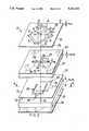
- the antennacomprises a conductive radiating patch (12) mounted upon the top face of a first planar dielectric layer (22). Attached to the sides of the patch (12) are conductive tuning stubs (20) which induce a 90 degree phase differential between dual linearly polarized signals to convert them into a circularly polarized signal. Attached to the bottom face of the dielectric layer (22) is a conductive ground plane (24) having two orthogonal elongated apertures (26, 28) (see FIG. 2). It is through the apertures (26, 28) that electromagnetic signals are coupled to the radiating patch (12).
- the inventionfurther comprises feeding means which includes a second dielectric layer (30), a third dielectric layer (32) having two conductive feed networks (38, 40) mounted on opposite faces, a fourth dielectric layer (34), and a second ground plane (36).
- the feeding meanselectromagnetically couples the radiating patch (12) to the input/output ports (48, 56) of the antenna. Due to the unique structure of the feed networks (38, 40) and the apertures (26, 28), two signals having different frequencies may be processed by the invention simultaneously. Thus, the invention is capable of dual frequency operation as well as circular polarization operation.
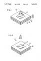
- FIG. 1is a perspective view of a preferred embodiment of the antenna 10 of the present invention.
- FIG. 2is an exploded perspective view of the antenna 10 of FIG. 1.
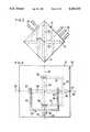
- FIG. 3is a top plan view of the radiating patch 12 and the underlying apertures 26, 28 of the invention showing their relative positioning.
- FIG. 4is a plan view of the preferred feed networks 38, 40 of the taken along view lines 4--4 of FIG. 2.
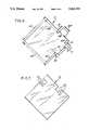
- FIG. 5is a perspective view of an integrated microwave antenna 10 in the process of being constructed.
- FIG. 6is a plan view of the radiating patch 12 of a specific implementation of the invention.
- FIG. 7is a plan view of an alternate embodiment of the radiating patch 12 of the invention.
- FIG. 1A perspective view of a preferred embodiment of the present invention is provided in FIG. 1, and an exploded view is shown in FIG. 2.
- the antenna 10comprises a radiating patch 12 mounted upon a dielectric layer 22, a ground plane 24 having two orthogonal elongated apertures 26 and 28, and feeding means comprising some or all of layers 30, 32, 34, and 36. All of the layers of the antenna 10 are substantially planar and are stacked one upon the other to form a single integrated antenna 10.
- the radiating patch 12constructed of a conductive material such as copper, is mounted upon the top face 21 of a dielectric layer 22 having a thickness t 1 and a dielectric constant e 1 .
- dielectric layer 22is a honeycomb dielectric composed of the material Nomex.
- Radiating patch 12preferably takes the shape of a square with each side having a dimension S.
- the two diagonal coplanar axes 14 and 16 of the square patch 12intersect each other at the center 18 of the square.
- a vertical axis 15 orthogonal to the plane of layer 22passes through the center 18 of the square patch 12.
- tuning stubs 20which serve to convert dual linearly polarized signals into a circularly polarized (CP) signal and vice versa.
- tuning stubs 20In transmit mode, tuning stubs 20 cause the phase of one of the linearly polarized signals to either lead or lag the phase of the other signal by 90 degrees, thereby producing the 90 degree phase difference needed for CP operation.
- the sense of polarization of the CP signalwill either be righthanded or lefthanded. The sense of polarization is controlled by the positioning and the dimensions of the tuning stubs 20.
- tuning stubs 20serve to extract the phase difference from a CP signal to produce two linearly polarized signals which are in phase. The design and operation of tuning stubs 20 will be described in further detail below.
- ground plane 24Abutting the bottom face 23 of dielectric layer 22 is conductive ground plane 24 having two elongated apertures 26, 28.
- Aperture 26has a length L 1 and a width W 1 .
- Aperture 28has a length L 2 and a width W 2 .
- the two apertures 26, 28intersect each other orthogonally at their respective midpoints 29 to form a cross-like structure.
- Ground plane 24is placed beneath dielectric layer 22 and positioned such that vertical axis 15 passes through the midpoints 29 of the apertures 26, 28; and each of the apertures 26, 28 lies parallel to one of the diagonal axes 14, 16 of the square radiating patch 12. This is illustrated more clearly in FIG. 3.
- each of the apertures 26, 28forms an angle substantially 45 degrees with each of the sides of the radiating patch 12. As will be discussed later, this 45 degree angle plays an important role in the proper functioning of the invention.
- the dielectric layer 22serves as the substrate for the radiator while the radiating patch 12 and the ground plane 24 form the radiating cavity in which electromagnetic signals are generated.
- the radiatoris electromagnetically coupled to the external environment through one or both of the slot apertures 26, 28 in the ground plane 24. For this reason, this type of antenna is referred to as an aperture coupled antenna.
- a feeding meansis necessary.
- this feeding meanstakes one of two forms.
- a first form of the feeding meanscomprises a dielectric layer 30 (such as a Nomex honeycomb dielectric) having a thickness t 2 and a dielectric constant e 2 , and a thin dielectric layer 32 abutting layer 30.
- Layer 32has a first microstrip feed network 38 on its top face 33, and a second microstrip feed network 40 orthogonal to the first network 38 on its bottom face 35. This is illustrated more clearly in FIG.
- feed network 38is drawn with solid lines to show that it is mounted upon the top face 33 of dielectric layer 32 while feed network 40 is drawn in dashed lines to show that it resides on the opposite (bottom) face 35 of layer 32.
- feed network 40is drawn in dashed lines to show that it resides on the opposite (bottom) face 35 of layer 32. Also indicated by broken lines in FIG. 4 is the projection of the aperture slots 26, 28 onto the plane of layer 32.
- the first feed network 38preferably comprises two elongated conductive microstrip elements 42 placed in parallel to each other and equidistant from a center plane 44.
- Center plane 44is orthogonal to the plane of dielectric layer 32 and bisects the projection of aperture 26.
- Microstrip elements 42extend into the middle portion of layer 32 to orthogonally intersect and overlap the projection of aperture 26 in two separate locations 50. The areas of overlap 50 will be referred to as coupling overlaps 50.
- Joining the two microstrip elements 42 and electromagnetically coupling them to input/output port 48is power combiner 46.
- Power combiner 46serves either to combine two signals propagating on elements 42 into a single signal or to separate a signal at the input/output port 48 into two equal power signals allowing each to propagate down a corresponding element 42.
- the entire feed network 38which may be constructed of a conductive material such as copper or gold, is symmetric about center plane 44.
- Feed network 40residing on the opposite face 35 of layer 32, is almost identical to the first feed network 38.
- Feed network 40comprises a pair of elongated conductive microstrip elements 52 placed in parallel to each other. The two elements 52 are coupled to each other and to input/output port 56 by power combiner 54.
- the microstrip elements 52extend into the middle section of layer 32 and intersect the projection of aperture 28 orthogonally at two distinct locations forming two coupling overlaps 58.
- Dividing the feed network 40 into two symmetrical portionsis center plane 60 which is orthogonal to both the plane of layer 32 and the center plane 44 of the first feed network 38. Center plane 60 also bisects the projection of aperture 28.
- the intersection of the two center planes 44, 60forms the vertical axis 15 (FIG. 2) of the antenna.
- a feeding means as thus far describedcomprising layers 30 and 32 forms a microstrip line feed circuit.
- dielectric layer 34(FIG. 2) having a thickness t 3 and a dielectric constant e 3 , abutting the lower face 35 of layer 32, and a second conductive ground plane 36 abutting layer 34.
- Dielectric layer 34again may be a honeycomb dielectric made of Nomex.
- a feeding means in this formis called a strip line feed circuit. Both the microstrip line and the strip line feed circuits as described will function adequately as feeding means for the present invention.
- antenna 10 of the present inventionhas several inherent advantages.
- aperture coupled antennascan be easily fabricated using integrated circuit techniques. As a result, they can be made to have relatively low profiles. They also are relatively light in weight.
- no probe solderingis necessary. While these advantages are inherent in all aperture coupled antennas, the present invention has other unique advantages. The operation of the invention will now be described.
- antenna 10 of the present inventionis capable of operating in both transmit and receive mode. Since the operation in receive mode is simply the reverse of operation in the transmit mode, only the transmit mode will be described in detail.
- antenna 10, in transmit modereceives an input signal at one of its input ports 48, 56. For the sake of discussion, it will be assumed that the input signal is received at port 48.
- the input signalenters antenna 10 at port 48 and propagates along port 48 until it encounters power combiner 46, at which time power combiner 46 separates the input signal into two half-signals with equal amplitude. Each of the half-signals propagates down a separate microstrip element 42 until it encounters its respective coupling overlap 50.
- the coupling overlaps 50represent the portions of the microstrip elements 42 which lie directly beneath both the aperture 26 and the radiating patch 12. It is this overlap 50 which allows the half-signals to couple, through the aperture 26, to the radiating patch 12, and thus, enter the radiator of antenna 10.
- the half-signalsexcite the radiating patch 12 and cause it to generate electromagnetic signals having a frequency determined by the frequency of the input signal.
- two orthogonal field mode signalsare generated, with both modes having substantially identical amplitude and phase.
- One of the requirements for CP operationis that two orthogonal field modes be generated with equal amplitude; thus, this requirement is satisfied.
- Each of the orthogonal modes generatedis aligned with a pair of parallel sides of the radiating patch 12, and if tuning stubs 20 were not present, the two modes would combine to produce net radiation linearly polarized in a direction perpendicular to aperture 26.
- the dimensions and the positioning of the tuning stubs 20primarily determine the sense of polarization of the signal as well as the frequency at which CP operation is achieved.
- the design of tuning stubs 20is not an exact science.
- the number, the dimensions, and the positioning of the stubs 20cannot be designed using equations, but rather must be determined experimentally.
- the inventionis like prior art CP antennas. But unlike prior art antennas, the present invention can be fine tuned to operate at a specific frequency without having to produce a new antenna 10 with each adjustment.
- the general operating frequency range of a patch antennais determined by the dimensions of the apertures 26, 28; the dimensions of the radiating patch 12; and the thickness and dielectric constants of the dielectric layers.
- the prior art devicesseek to accommodate CP operation at a particular frequency by specifically designing the integral elements of the antenna, such as the apertures in the ground plane.
- the integral elements of the antennasuch as the apertures in the ground plane.
- another antenna with different specificationsmust be built. Even if the adjustment is slight, it is still necessary to rebuild the antenna because an integral element of the antenna has to be altered. This is clumsy and expensive, and an unsatisfactory way of solving the problem of designing antennas to operate at a specific frequency.
- CP operation in the present inventionis governed primarily by the tuning stubs 20.
- Tuning stubs 20are not integral elements of antenna 10; thus, they may be adjusted without building an entirely new antenna.
- To design an antenna 10 to achieve CP operation at a particular frequencyone begins with an integrated antenna 62 like that shown in FIG. 5, which is an antenna substantially identical to that shown in FIG. 1 except that no tuning stubs 20 are present.
- antenna 62is able to generate only linearly polarized signals.
- the design of the stubs 20begins by placing a set of removable planar conductive stubs 20 onto the top face 21 of dielectric layer 22.
- Removable stubs 20may be made of a conductive material such as copper. Stubs 20 should be placed such that they lie flat on top of layer 22, and are positioned such that each stub 20 contacts one of the sides of the radiating patch 12. The number, the size, and the positioning of the stubs 20 are all parameters chosen by the designer. The stubs 20 may all be placed on only one side of the patch 12, or they may be placed on a plurality of sides. After the stubs 20 have been placed upon layer 22, measurements should be taken to ascertain whether CP operation has been achieved and whether it takes place at the proper frequency. If not, stubs 20 can be moved, other stubs 20 may be added, or different sized stubs 20 can be employed. After several iterations, a working model should be obtained. Once the number, size, and locations of the stubs 20 are known, a permanent integrated antenna like that shown in FIG. 1 can be constructed.
- the entire design processthus requires only one basic antenna 10. No new antenna 10 needs to be built for any of the adjustments.
- the same basic antenna 10may be used to design a plurality of antennas 10 so long as the desired CP operating frequency is within the general operating frequency range of the basic antenna 10.
- the antenna 10 of the present inventioncan be designed much more easily, efficiently, and cost effectively than the antennas of the prior art.
- Another advantage of the inventionis that it is capable of dual frequency operation; that is, the invention is operable at two different frequencies simultaneously. Dual frequency operation is quite desirable because it essentially allows a single antenna 10 to do the work of two. This, in turn, reduces the number of antennas 10 needed for any particular application. Dual frequency operation is made possible by the special configuration of the antenna 10.
- the feed networks 38, 40are designed to lie orthogonal to each other and on opposite sides of dielectric layer 32, to electromagnetically isolate one from the other.
- the apertures 26, 28 in ground plane 24are placed orthogonal to each other to ensure that they function separately with minimal interaction.
- each of the feed networks 38, 40is strategically placed relative to the apertures 26, 28 such that each network 38, 40 interacts with only one of the apertures 26, 28. All of these features in combination enable the antenna 10 to operate at two different frequencies simultaneously while keeping the two frequencies separate. In essence, the present invention is two antennas 10 in one. This dual frequency capability greatly enhances the versatility of the invention and allows it to accommodate many different uses.
- the antenna 10 of the present inventionmay be used to simultaneously generate CP signals at two distinct frequencies.
- Thiscan be accomplished by attaching two sets of tuning stubs 20 to the radiating patch 12, with each set of stubs 20 designed to achieve CP operation at a different frequency.
- tuning stubs 20are very high Q devices. That is, they will affect only those signals which are within a very narrow frequency range. Signals outside this range will not be significantly affected. Therefore, as long as the two frequencies at which CP operation is desired are sufficiently far apart, the first set of stubs 20 will not affect the frequencies affected by the second set of stubs 20, and vice versa. As a result, frequency isolation is achieved between the two sets of stubs 20, and two CP signals having different frequencies can be produced.
- the inventionis also capable of simultaneously generating a CP signal and a linearly polarized signal. This may be accomplished by attaching only one set of tuning stubs 20 to the radiating patch 12. The one set of tuning stubs 20 will convert linearly polarized signals at the proper frequency to CP signals. However, as previously mentioned, tuning stubs 20 will affect only those signals within a narrow frequency range. Where a linearly polarized signal is generated having a frequency sufficiently outside the range of effect of the tuning stubs 20, that signal remains a linearly polarized signal. The result is that both CP and linearly polarized signals may be generated by the same antenna 10.
- Another capability of the invention 10is that it can transmit and receive signals at the same time.
- the uses for the invention 10 thus far describedare only examples of some of the capabilities of the invention 10. Other implementations will be apparent to those skilled in the art.
- a practical implementation of the invention 10comprises the radiating patch 12 shown in FIG. 6 mounted upon dielectric layer 22, ground plane 24, dielectric layer 30, and dielectric layer 32 having feed networks 38, 40.
- Dielectric layers 22 and 30are honeycomb dielectrics made of the material Nomex. Because layers 22, 30 are honeycomb dielectrics, their dielectric constants e 1 , e 2 are substantially equal to 1.
- the dimensions of the antennaare as follows:
- radiating patch 12The dimensions of radiating patch 12 are shown in FIG. 6. This particular antenna 10 achieves circular polarization at two frequencies: (1) 2.0 GHz; and (2) 2.34 GHz. It can accommodate both of these frequencies simultaneously.
- the scope of the invention 10should not be construed to be so limited. Many modifications may be made by those skilled in the art with the benefit of this disclosure without departing from the spirit of the invention 10.
- the 90 degree phase shift necessary for CP operationmay be obtained by using notches cut into the radiating patch instead of tuning stubs 20. This is illustrated in FIG. 7, wherein a plurality of notches 72 are cut from the sides of radiating patch 12. Depending upon the number of notches 72, their dimensions, and their positioning, CP operation may be achieved at various frequencies.
Landscapes
- Physics & Mathematics (AREA)
- Electromagnetism (AREA)
- Waveguide Aerials (AREA)
Abstract
Description
______________________________________ L.sub.1 = 1.64 inches; L.sub.2 = 1.5 inches; W.sub.1 = .05 inches; W.sub.2 = .05 inches; t.sub.1 = .185 inches; and t.sub.2 = .06 inches. ______________________________________
Claims (9)
Priority Applications (1)
| Application Number | Priority Date | Filing Date | Title |
|---|---|---|---|
| US07/884,512US5241321A (en) | 1992-05-15 | 1992-05-15 | Dual frequency circularly polarized microwave antenna |
Applications Claiming Priority (1)
| Application Number | Priority Date | Filing Date | Title |
|---|---|---|---|
| US07/884,512US5241321A (en) | 1992-05-15 | 1992-05-15 | Dual frequency circularly polarized microwave antenna |
Publications (1)
| Publication Number | Publication Date |
|---|---|
| US5241321Atrue US5241321A (en) | 1993-08-31 |
Family
ID=25384789
Family Applications (1)
| Application Number | Title | Priority Date | Filing Date |
|---|---|---|---|
| US07/884,512Expired - LifetimeUS5241321A (en) | 1992-05-15 | 1992-05-15 | Dual frequency circularly polarized microwave antenna |
Country Status (1)
| Country | Link |
|---|---|
| US (1) | US5241321A (en) |
Cited By (276)
| Publication number | Priority date | Publication date | Assignee | Title |
|---|---|---|---|---|
| US5408241A (en)* | 1993-08-20 | 1995-04-18 | Ball Corporation | Apparatus and method for tuning embedded antenna |
| US5420596A (en)* | 1993-11-26 | 1995-05-30 | Motorola, Inc. | Quarter-wave gap-coupled tunable strip antenna |
| US5448250A (en)* | 1992-09-28 | 1995-09-05 | Pilkington Plc | Laminar microstrip patch antenna |
| US5448252A (en)* | 1994-03-15 | 1995-09-05 | The United States Of America As Represented By The Secretary Of The Air Force | Wide bandwidth microstrip patch antenna |
| EP0700117A1 (en)* | 1994-08-30 | 1996-03-06 | Pilkington Plc | Patch antenna assembly |
| US5515057A (en)* | 1994-09-06 | 1996-05-07 | Trimble Navigation Limited | GPS receiver with N-point symmetrical feed double-frequency patch antenna |
| US5519406A (en)* | 1994-03-09 | 1996-05-21 | Matsushita Electric Works, Ltd. | Low profile polarization diversity planar antenna |
| DE19523694A1 (en)* | 1995-06-29 | 1997-01-02 | Fuba Automotive Gmbh | Planar antenna, esp. for frequencies in GHz region |
| US5596336A (en)* | 1995-06-07 | 1997-01-21 | Trw Inc. | Low profile TEM mode slot array antenna |
| US5661493A (en)* | 1994-12-02 | 1997-08-26 | Spar Aerospace Limited | Layered dual frequency antenna array |
| US5666125A (en)* | 1993-03-17 | 1997-09-09 | Luxon; Norval N. | Radiation shielding and range extending antenna assembly |
| US5668558A (en)* | 1995-03-31 | 1997-09-16 | Daewoo Electronics Co., Ltd. | Apparatus capable of receiving circularly polarized signals |
| WO1997043799A1 (en)* | 1996-05-13 | 1997-11-20 | Allgon Ab | Flat antenna |
| US5691734A (en)* | 1994-06-01 | 1997-11-25 | Alan Dick & Company Limited | Dual polarizating antennae |
| EP0831547A3 (en)* | 1996-09-20 | 1998-04-01 | Murata Manufacturing Co., Ltd. | Microstrip antenna |
| US5752204A (en)* | 1996-04-01 | 1998-05-12 | Telefonaktiebolaget L M Ericsson (Publ) | Antenna assembly for radiotelephonic device |
| WO1998033234A1 (en)* | 1997-01-24 | 1998-07-30 | Allgon Ab | A substantially flat, aperture-coupled antenna element |
| WO1998036470A1 (en)* | 1997-02-14 | 1998-08-20 | Telefonaktiebolaget Lm Ericsson | Device in antenna units |
| FR2761532A1 (en)* | 1997-03-31 | 1998-10-02 | Samsung Electronics Co Ltd | CAVITY MICRO-TAPE DIPOLAR NETWORK ANTENNA |
| WO1998049741A1 (en)* | 1997-04-30 | 1998-11-05 | Telefonaktiebolaget Lm Ericsson (Publ) | Microwave antenna system and method |
| US5835057A (en)* | 1996-01-26 | 1998-11-10 | Kvh Industries, Inc. | Mobile satellite communication system including a dual-frequency, low-profile, self-steering antenna assembly |
| WO1999008337A1 (en)* | 1997-07-28 | 1999-02-18 | Telenor As | Antenna and method using tuning stub |
| EP0901185A1 (en)* | 1997-07-29 | 1999-03-10 | Alcatel | Dual polarisation patch antenna |
| WO1999031757A1 (en)* | 1997-12-12 | 1999-06-24 | Allgon Ab | Dual band antenna |
| US5952970A (en)* | 1995-05-31 | 1999-09-14 | Murata Manfacturing Co., Ltd. | Antenna device and communication apparatus incorporating the same |
| DE19815003A1 (en)* | 1998-04-03 | 1999-10-14 | Bosch Gmbh Robert | Dual polarized antenna element |
| US5977915A (en)* | 1997-06-27 | 1999-11-02 | Telefonaktiebolaget Lm Ericsson | Microstrip structure |
| GB2304462B (en)* | 1995-08-21 | 2000-02-23 | Motorola Inc | Dual function antenna structure and a portable radio having same |
| US6037903A (en)* | 1998-08-05 | 2000-03-14 | California Amplifier, Inc. | Slot-coupled array antenna structures |
| US6054953A (en)* | 1998-12-10 | 2000-04-25 | Allgon Ab | Dual band antenna |
| DE19855115A1 (en)* | 1998-11-30 | 2000-06-08 | Technisat Elektronik Thueringe | Multi-layer antenna arrangement |
| GB2346012A (en)* | 1999-01-22 | 2000-07-26 | Finglas Tech Ltd | Dual polarisation antennas |
| US6095820A (en)* | 1995-10-27 | 2000-08-01 | Rangestar International Corporation | Radiation shielding and range extending antenna assembly |
| US6140966A (en)* | 1997-07-08 | 2000-10-31 | Nokia Mobile Phones Limited | Double resonance antenna structure for several frequency ranges |
| FR2799580A1 (en)* | 1999-10-12 | 2001-04-13 | Univ Rennes | PRINTED BROADBAND PRINTED ANTENNA WITH LOW CROSS POLARIZATION LEVEL AND CORRESPONDING ANTENNA ARRAY |
| US6222493B1 (en)* | 1998-05-15 | 2001-04-24 | Alcatel | Device for transmitting and receiving microwaves subjected to circular polarization |
| US6236367B1 (en) | 1998-09-25 | 2001-05-22 | Deltec Telesystems International Limited | Dual polarised patch-radiating element |
| US6252553B1 (en) | 2000-01-05 | 2001-06-26 | The Mitre Corporation | Multi-mode patch antenna system and method of forming and steering a spatial null |
| GB2358963A (en)* | 2000-02-02 | 2001-08-08 | Nokia Mobile Phones Ltd | Mobile 'phone antenna |
| WO2001059879A1 (en)* | 2000-02-08 | 2001-08-16 | Q-Free Asa | Antenna for transponder |
| US6288679B1 (en)* | 2000-05-31 | 2001-09-11 | Lucent Technologies Inc. | Single element antenna structure with high isolation |
| US6304220B1 (en)* | 1999-08-05 | 2001-10-16 | Alcatel | Antenna with stacked resonant structures and a multi-frequency radiocommunications system including it |
| US6377217B1 (en) | 1999-09-14 | 2002-04-23 | Paratek Microwave, Inc. | Serially-fed phased array antennas with dielectric phase shifters |
| US6388620B1 (en)* | 2000-06-13 | 2002-05-14 | Hughes Electronics Corporation | Slot-coupled patch reflect array element for enhanced gain-band width performance |
| US20020113737A1 (en)* | 1999-11-12 | 2002-08-22 | France Telecom | Dual band printed antenna |
| US6445346B2 (en)* | 2000-04-27 | 2002-09-03 | Sarnoff Corporation | Planar polarizer feed network for a dual circular polarized antenna array |
| US6531984B1 (en)* | 1999-10-29 | 2003-03-11 | Telefonaktiebolaget Lm Ericsson (Publ) | Dual-polarized antenna |
| NL1019022C2 (en)* | 2001-09-24 | 2003-03-25 | Thales Nederland Bv | Printed antenna powered by a patch. |
| US6549166B2 (en)* | 2001-08-22 | 2003-04-15 | The Boeing Company | Four-port patch antenna |
| US6583762B2 (en)* | 2001-01-11 | 2003-06-24 | The Furukawa Electric Co., Ltd. | Chip antenna and method of manufacturing the same |
| US6636179B1 (en)* | 1999-04-08 | 2003-10-21 | Jong-Myung Woo | V-type aperture coupled circular polarization patch antenna using microstrip line |
| US20030201942A1 (en)* | 2002-04-25 | 2003-10-30 | Ethertronics, Inc. | Low-profile, multi-frequency, multi-band, capacitively loaded magnetic dipole antenna |
| US20030214438A1 (en)* | 2002-05-20 | 2003-11-20 | Hatch Robert Jason | Broadband I-slot microstrip patch antenna |
| WO2004030141A1 (en)* | 2002-09-23 | 2004-04-08 | Robert Bosch Gmbh | Device for transmitting or emitting high-frequency waves |
| US20040104848A1 (en)* | 2002-12-03 | 2004-06-03 | Ethertronics, Inc. | Multiple frequency antennas with reduced space and relative assembly |
| WO2004047222A1 (en)* | 2002-11-18 | 2004-06-03 | Ethertronics, Inc. | Multiple frequency capacitively loaded magnetic dipole |
| US20040119642A1 (en)* | 2002-12-23 | 2004-06-24 | Truthan Robert E. | Singular feed broadband aperture coupled circularly polarized patch antenna |
| US20040125021A1 (en)* | 2001-03-05 | 2004-07-01 | Marco Munk | Multilayered slot-coupled antenna device |
| US6844851B2 (en) | 2002-05-27 | 2005-01-18 | Samsung Thales Co., Ltd. | Planar antenna having linear and circular polarization |
| US20050052321A1 (en)* | 2003-09-09 | 2005-03-10 | Yoonjae Lee | Multifrequency antenna with reduced rear radiation and reception |
| US20050110685A1 (en)* | 2003-08-08 | 2005-05-26 | Frederik Du Toit Cornelis | Stacked patch antenna |
| US6906667B1 (en) | 2002-02-14 | 2005-06-14 | Ethertronics, Inc. | Multi frequency magnetic dipole antenna structures for very low-profile antenna applications |
| US6919844B1 (en)* | 2004-01-20 | 2005-07-19 | The United States Of America As Represented By The Secretary Of The Navy | Reduced size GPS microstrip antenna with a slot |
| US20050200528A1 (en)* | 2004-03-12 | 2005-09-15 | Curt Carrender | Switching patch antenna |
| US20050206575A1 (en)* | 2000-12-21 | 2005-09-22 | Chadwick Peter E | Dual polarisation antenna |
| US20050264451A1 (en)* | 2004-05-25 | 2005-12-01 | Masayoshi Aikawa | Planar array antenna |
| US20060139223A1 (en)* | 2004-12-29 | 2006-06-29 | Agc Automotive Americas R&D Inc. | Slot coupling patch antenna |
| GB2427759A (en)* | 2005-06-27 | 2007-01-03 | Samsung Electronics Co Ltd | Antenna element coupled to a differential feed arrangement |
| WO2007106976A1 (en)* | 2006-03-17 | 2007-09-27 | Tenxc Wireless Inc. | Tri-polar antenna array element |
| FR2905526A1 (en)* | 2006-09-04 | 2008-03-07 | Commissariat Energie Atomique | MULTI-ANTENNA SYSTEM WITH POLARIZATION DIVERSITY |
| US20080079644A1 (en)* | 2006-09-29 | 2008-04-03 | Dajun Cheng | Multi-band slot resonating ring antenna |
| EP1914835A1 (en)* | 2006-10-20 | 2008-04-23 | Research In Motion Limited | Mobile wireless communications device with multiple RF transceivers using a common antenna at a same time and related methods |
| US20080094290A1 (en)* | 2006-10-20 | 2008-04-24 | Research In Motion Limited | Mobile wireless communications device with multiple rf transceivers using a common antenna at a same time and related methods |
| US20080158066A1 (en)* | 2006-12-29 | 2008-07-03 | Delta Networks, Inc. | Aperture coupled microstrip antenna |
| US7505002B2 (en)* | 2006-12-04 | 2009-03-17 | Agc Automotive Americas R&D, Inc. | Beam tilting patch antenna using higher order resonance mode |
| US20090091498A1 (en)* | 2007-10-09 | 2009-04-09 | Chih-Ming Chen | Dual polarization antenna device for creating a dual band function |
| US20090163214A1 (en)* | 2006-03-17 | 2009-06-25 | Tenxc Wireless Inc. | Asymmetrical beams for spectrum efficiency |
| US20090195469A1 (en)* | 2008-01-31 | 2009-08-06 | Lim Chan-Ping | Antenna system and antenna thereof |
| US20090213013A1 (en)* | 2008-02-25 | 2009-08-27 | Bjorn Lindmark | Antenna feeding arrangement |
| US7586451B2 (en) | 2006-12-04 | 2009-09-08 | Agc Automotive Americas R&D, Inc. | Beam-tilted cross-dipole dielectric antenna |
| US20090256773A1 (en)* | 2008-04-11 | 2009-10-15 | Bjorn Lindmark | Antenna isolation |
| US20100001921A1 (en)* | 2008-07-07 | 2010-01-07 | Sensormatic Electronics Corporation | Switchable patch antenna for rfid shelf reader system |
| US20100141532A1 (en)* | 2008-02-25 | 2010-06-10 | Jesper Uddin | Antenna feeding arrangement |
| US20100171675A1 (en)* | 2007-06-06 | 2010-07-08 | Carmen Borja | Dual-polarized radiating element, dual-band dual-polarized antenna assembly and dual-polarized antenna array |
| WO2010115191A1 (en)* | 2009-04-03 | 2010-10-07 | Board Of Trustees Of The University Of Arkansas | Circularly polarized microstrip antennas |
| US20110012788A1 (en)* | 2009-07-14 | 2011-01-20 | Hong Kong Applied Science And Technology Research Institute Co., Ltd. | Miniature Circularly Polarized Folded Patch Antenna |
| USD631478S1 (en)* | 2010-01-11 | 2011-01-25 | Datalogic Scanning, Inc. | Weigh platter or cover for a data reader |
| USD634738S1 (en) | 2008-01-30 | 2011-03-22 | Yfy Rfid Technologies Company Limited | RFID antenna |
| US7999745B2 (en)* | 2007-08-15 | 2011-08-16 | Powerwave Technologies, Inc. | Dual polarization antenna element with dielectric bandwidth compensation and improved cross-coupling |
| US20110242863A1 (en)* | 2010-03-31 | 2011-10-06 | Kookmin University Industry Academy Cooperation Foundation | Patch antenna and rectenna using the same |
| DE102011011494A1 (en)* | 2011-02-17 | 2012-09-06 | Kathrein-Werke Kg | Patch antenna and frequency tuning method of such a patch antenna |
| TWI383540B (en)* | 2009-04-28 | 2013-01-21 | Advanced Connection Tech Inc | Slot antenna |
| US20130120195A1 (en)* | 2011-05-05 | 2013-05-16 | Maxtena | Antenna system for handheld satellite communication devices |
| US20130141296A1 (en)* | 2011-12-01 | 2013-06-06 | Motorola Solutions, Inc. | Cavity backed cross-slot antenna apparatus and method |
| US8472904B2 (en) | 2009-03-30 | 2013-06-25 | The Charles Stark Draper Laboratory, Inc. | Antenna with integrated tuning detection elements |
| US8581773B1 (en) | 2009-10-15 | 2013-11-12 | The Boeing Company | Dual frequency transmitter |
| US20140035786A1 (en)* | 2012-07-31 | 2014-02-06 | Cambium Networks Limited | Patch antenna |
| CN103682603A (en)* | 2012-09-07 | 2014-03-26 | 鸿富锦精密工业(深圳)有限公司 | Dual-frequency and dual-pole antenna |
| US20140145891A1 (en)* | 2012-11-26 | 2014-05-29 | Raytheon Company | Dual Linear and Circularly Polarized Patch Radiator |
| US20140184456A1 (en)* | 2013-01-03 | 2014-07-03 | Ajou University Industry-Academic Cooperation Foundation | Antenna and communication system including the antenna |
| US20150180116A1 (en)* | 2011-12-08 | 2015-06-25 | Denki Kogyo Co., Ltd. | Transmitting-receiving-separated dual-polarization antenna |
| US20150357718A1 (en)* | 2014-06-05 | 2015-12-10 | Rosemount Aerospace Inc. | Circularly-polarized patch antenna |
| WO2016098201A1 (en)* | 2014-12-17 | 2016-06-23 | 株式会社日立製作所 | Rotation-polarized antenna, transmitting and receiving module, elevator machine control system and transformer station control system |
| GB2534689A (en)* | 2014-02-18 | 2016-08-03 | Filtronic Wireless Ab | Broadband antenna, multiband antenna unit and antenna array |
| US20160301135A1 (en)* | 2008-12-23 | 2016-10-13 | Skycross, Inc. | Dual feed antenna |
| CN106169650A (en)* | 2016-08-31 | 2016-11-30 | 上海捷士太通讯技术有限公司 | A kind of broadband high isolation 2x2MIMO circular polarization microstrip antenna |
| US20170062940A1 (en)* | 2015-08-28 | 2017-03-02 | Amphenol Corporation | Compact wideband dual polarized dipole |
| US9608740B2 (en) | 2015-07-15 | 2017-03-28 | At&T Intellectual Property I, L.P. | Method and apparatus for launching a wave mode that mitigates interference |
| US9615269B2 (en) | 2014-10-02 | 2017-04-04 | At&T Intellectual Property I, L.P. | Method and apparatus that provides fault tolerance in a communication network |
| US9628116B2 (en) | 2015-07-14 | 2017-04-18 | At&T Intellectual Property I, L.P. | Apparatus and methods for transmitting wireless signals |
| US9640850B2 (en) | 2015-06-25 | 2017-05-02 | At&T Intellectual Property I, L.P. | Methods and apparatus for inducing a non-fundamental wave mode on a transmission medium |
| US9667317B2 (en) | 2015-06-15 | 2017-05-30 | At&T Intellectual Property I, L.P. | Method and apparatus for providing security using network traffic adjustments |
| US9674711B2 (en) | 2013-11-06 | 2017-06-06 | At&T Intellectual Property I, L.P. | Surface-wave communications and methods thereof |
| US9685992B2 (en) | 2014-10-03 | 2017-06-20 | At&T Intellectual Property I, L.P. | Circuit panel network and methods thereof |
| US9692101B2 (en) | 2014-08-26 | 2017-06-27 | At&T Intellectual Property I, L.P. | Guided wave couplers for coupling electromagnetic waves between a waveguide surface and a surface of a wire |
| RU172145U1 (en)* | 2016-12-30 | 2017-06-29 | Общество С Ограниченной Ответственностью "Научно-Производственное Предприятие Антэкс" | BROADBAND DIRECTED ANTENNA WITH TWO ORTHOGONAL POLARIZATIONS |
| US9699785B2 (en) | 2012-12-05 | 2017-07-04 | At&T Intellectual Property I, L.P. | Backhaul link for distributed antenna system |
| US9705561B2 (en) | 2015-04-24 | 2017-07-11 | At&T Intellectual Property I, L.P. | Directional coupling device and methods for use therewith |
| US9705610B2 (en) | 2014-10-21 | 2017-07-11 | At&T Intellectual Property I, L.P. | Transmission device with impairment compensation and methods for use therewith |
| US9722318B2 (en) | 2015-07-14 | 2017-08-01 | At&T Intellectual Property I, L.P. | Method and apparatus for coupling an antenna to a device |
| US9729197B2 (en) | 2015-10-01 | 2017-08-08 | At&T Intellectual Property I, L.P. | Method and apparatus for communicating network management traffic over a network |
| US9735833B2 (en) | 2015-07-31 | 2017-08-15 | At&T Intellectual Property I, L.P. | Method and apparatus for communications management in a neighborhood network |
| US9742521B2 (en) | 2014-11-20 | 2017-08-22 | At&T Intellectual Property I, L.P. | Transmission device with mode division multiplexing and methods for use therewith |
| US9742462B2 (en) | 2014-12-04 | 2017-08-22 | At&T Intellectual Property I, L.P. | Transmission medium and communication interfaces and methods for use therewith |
| US9748626B2 (en) | 2015-05-14 | 2017-08-29 | At&T Intellectual Property I, L.P. | Plurality of cables having different cross-sectional shapes which are bundled together to form a transmission medium |
| US9749053B2 (en) | 2015-07-23 | 2017-08-29 | At&T Intellectual Property I, L.P. | Node device, repeater and methods for use therewith |
| US9749013B2 (en) | 2015-03-17 | 2017-08-29 | At&T Intellectual Property I, L.P. | Method and apparatus for reducing attenuation of electromagnetic waves guided by a transmission medium |
| US9762289B2 (en) | 2014-10-14 | 2017-09-12 | At&T Intellectual Property I, L.P. | Method and apparatus for transmitting or receiving signals in a transportation system |
| US9769128B2 (en) | 2015-09-28 | 2017-09-19 | At&T Intellectual Property I, L.P. | Method and apparatus for encryption of communications over a network |
| US9769020B2 (en) | 2014-10-21 | 2017-09-19 | At&T Intellectual Property I, L.P. | Method and apparatus for responding to events affecting communications in a communication network |
| US9768833B2 (en) | 2014-09-15 | 2017-09-19 | At&T Intellectual Property I, L.P. | Method and apparatus for sensing a condition in a transmission medium of electromagnetic waves |
| US9780834B2 (en) | 2014-10-21 | 2017-10-03 | At&T Intellectual Property I, L.P. | Method and apparatus for transmitting electromagnetic waves |
| US9787412B2 (en) | 2015-06-25 | 2017-10-10 | At&T Intellectual Property I, L.P. | Methods and apparatus for inducing a fundamental wave mode on a transmission medium |
| US9793955B2 (en) | 2015-04-24 | 2017-10-17 | At&T Intellectual Property I, Lp | Passive electrical coupling device and methods for use therewith |
| US9793951B2 (en) | 2015-07-15 | 2017-10-17 | At&T Intellectual Property I, L.P. | Method and apparatus for launching a wave mode that mitigates interference |
| US9793954B2 (en) | 2015-04-28 | 2017-10-17 | At&T Intellectual Property I, L.P. | Magnetic coupling device and methods for use therewith |
| US9800327B2 (en) | 2014-11-20 | 2017-10-24 | At&T Intellectual Property I, L.P. | Apparatus for controlling operations of a communication device and methods thereof |
| US9820146B2 (en) | 2015-06-12 | 2017-11-14 | At&T Intellectual Property I, L.P. | Method and apparatus for authentication and identity management of communicating devices |
| US9838078B2 (en) | 2015-07-31 | 2017-12-05 | At&T Intellectual Property I, L.P. | Method and apparatus for exchanging communication signals |
| US9838896B1 (en) | 2016-12-09 | 2017-12-05 | At&T Intellectual Property I, L.P. | Method and apparatus for assessing network coverage |
| US9847566B2 (en) | 2015-07-14 | 2017-12-19 | At&T Intellectual Property I, L.P. | Method and apparatus for adjusting a field of a signal to mitigate interference |
| US9847850B2 (en) | 2014-10-14 | 2017-12-19 | At&T Intellectual Property I, L.P. | Method and apparatus for adjusting a mode of communication in a communication network |
| US9853342B2 (en) | 2015-07-14 | 2017-12-26 | At&T Intellectual Property I, L.P. | Dielectric transmission medium connector and methods for use therewith |
| US9860075B1 (en) | 2016-08-26 | 2018-01-02 | At&T Intellectual Property I, L.P. | Method and communication node for broadband distribution |
| US9866309B2 (en) | 2015-06-03 | 2018-01-09 | At&T Intellectual Property I, Lp | Host node device and methods for use therewith |
| US9866276B2 (en) | 2014-10-10 | 2018-01-09 | At&T Intellectual Property I, L.P. | Method and apparatus for arranging communication sessions in a communication system |
| US9865911B2 (en) | 2015-06-25 | 2018-01-09 | At&T Intellectual Property I, L.P. | Waveguide system for slot radiating first electromagnetic waves that are combined into a non-fundamental wave mode second electromagnetic wave on a transmission medium |
| US9871283B2 (en) | 2015-07-23 | 2018-01-16 | At&T Intellectual Property I, Lp | Transmission medium having a dielectric core comprised of plural members connected by a ball and socket configuration |
| US9871282B2 (en) | 2015-05-14 | 2018-01-16 | At&T Intellectual Property I, L.P. | At least one transmission medium having a dielectric surface that is covered at least in part by a second dielectric |
| US9871558B2 (en) | 2014-10-21 | 2018-01-16 | At&T Intellectual Property I, L.P. | Guided-wave transmission device and methods for use therewith |
| US9876570B2 (en) | 2015-02-20 | 2018-01-23 | At&T Intellectual Property I, Lp | Guided-wave transmission device with non-fundamental mode propagation and methods for use therewith |
| US9876264B2 (en) | 2015-10-02 | 2018-01-23 | At&T Intellectual Property I, Lp | Communication system, guided wave switch and methods for use therewith |
| US9876605B1 (en) | 2016-10-21 | 2018-01-23 | At&T Intellectual Property I, L.P. | Launcher and coupling system to support desired guided wave mode |
| US9882257B2 (en) | 2015-07-14 | 2018-01-30 | At&T Intellectual Property I, L.P. | Method and apparatus for launching a wave mode that mitigates interference |
| US9887447B2 (en) | 2015-05-14 | 2018-02-06 | At&T Intellectual Property I, L.P. | Transmission medium having multiple cores and methods for use therewith |
| US9893795B1 (en) | 2016-12-07 | 2018-02-13 | At&T Intellectual Property I, Lp | Method and repeater for broadband distribution |
| US9906269B2 (en) | 2014-09-17 | 2018-02-27 | At&T Intellectual Property I, L.P. | Monitoring and mitigating conditions in a communication network |
| US9904535B2 (en) | 2015-09-14 | 2018-02-27 | At&T Intellectual Property I, L.P. | Method and apparatus for distributing software |
| US9912419B1 (en) | 2016-08-24 | 2018-03-06 | At&T Intellectual Property I, L.P. | Method and apparatus for managing a fault in a distributed antenna system |
| US9912381B2 (en) | 2015-06-03 | 2018-03-06 | At&T Intellectual Property I, Lp | Network termination and methods for use therewith |
| US9912027B2 (en) | 2015-07-23 | 2018-03-06 | At&T Intellectual Property I, L.P. | Method and apparatus for exchanging communication signals |
| US9911020B1 (en) | 2016-12-08 | 2018-03-06 | At&T Intellectual Property I, L.P. | Method and apparatus for tracking via a radio frequency identification device |
| US9912033B2 (en) | 2014-10-21 | 2018-03-06 | At&T Intellectual Property I, Lp | Guided wave coupler, coupling module and methods for use therewith |
| US9913139B2 (en) | 2015-06-09 | 2018-03-06 | At&T Intellectual Property I, L.P. | Signal fingerprinting for authentication of communicating devices |
| US9917341B2 (en) | 2015-05-27 | 2018-03-13 | At&T Intellectual Property I, L.P. | Apparatus and method for launching electromagnetic waves and for modifying radial dimensions of the propagating electromagnetic waves |
| US9927517B1 (en) | 2016-12-06 | 2018-03-27 | At&T Intellectual Property I, L.P. | Apparatus and methods for sensing rainfall |
| US9930668B2 (en) | 2013-05-31 | 2018-03-27 | At&T Intellectual Property I, L.P. | Remote distributed antenna system |
| US9948354B2 (en) | 2015-04-28 | 2018-04-17 | At&T Intellectual Property I, L.P. | Magnetic coupling device with reflective plate and methods for use therewith |
| US9948333B2 (en) | 2015-07-23 | 2018-04-17 | At&T Intellectual Property I, L.P. | Method and apparatus for wireless communications to mitigate interference |
| US9948355B2 (en) | 2014-10-21 | 2018-04-17 | At&T Intellectual Property I, L.P. | Apparatus for providing communication services and methods thereof |
| US9954287B2 (en) | 2014-11-20 | 2018-04-24 | At&T Intellectual Property I, L.P. | Apparatus for converting wireless signals and electromagnetic waves and methods thereof |
| US9954286B2 (en) | 2014-10-21 | 2018-04-24 | At&T Intellectual Property I, L.P. | Guided-wave transmission device with non-fundamental mode propagation and methods for use therewith |
| US9967173B2 (en) | 2015-07-31 | 2018-05-08 | At&T Intellectual Property I, L.P. | Method and apparatus for authentication and identity management of communicating devices |
| US9973940B1 (en) | 2017-02-27 | 2018-05-15 | At&T Intellectual Property I, L.P. | Apparatus and methods for dynamic impedance matching of a guided wave launcher |
| US9991580B2 (en) | 2016-10-21 | 2018-06-05 | At&T Intellectual Property I, L.P. | Launcher and coupling system for guided wave mode cancellation |
| US9997819B2 (en) | 2015-06-09 | 2018-06-12 | At&T Intellectual Property I, L.P. | Transmission medium and method for facilitating propagation of electromagnetic waves via a core |
| US9999038B2 (en) | 2013-05-31 | 2018-06-12 | At&T Intellectual Property I, L.P. | Remote distributed antenna system |
| US9998870B1 (en) | 2016-12-08 | 2018-06-12 | At&T Intellectual Property I, L.P. | Method and apparatus for proximity sensing |
| US10009063B2 (en) | 2015-09-16 | 2018-06-26 | At&T Intellectual Property I, L.P. | Method and apparatus for use with a radio distributed antenna system having an out-of-band reference signal |
| US10009065B2 (en) | 2012-12-05 | 2018-06-26 | At&T Intellectual Property I, L.P. | Backhaul link for distributed antenna system |
| US10009067B2 (en) | 2014-12-04 | 2018-06-26 | At&T Intellectual Property I, L.P. | Method and apparatus for configuring a communication interface |
| US10020844B2 (en) | 2016-12-06 | 2018-07-10 | T&T Intellectual Property I, L.P. | Method and apparatus for broadcast communication via guided waves |
| US10027398B2 (en) | 2015-06-11 | 2018-07-17 | At&T Intellectual Property I, Lp | Repeater and methods for use therewith |
| US10027397B2 (en) | 2016-12-07 | 2018-07-17 | At&T Intellectual Property I, L.P. | Distributed antenna system and methods for use therewith |
| US10033107B2 (en) | 2015-07-14 | 2018-07-24 | At&T Intellectual Property I, L.P. | Method and apparatus for coupling an antenna to a device |
| US10033108B2 (en) | 2015-07-14 | 2018-07-24 | At&T Intellectual Property I, L.P. | Apparatus and methods for generating an electromagnetic wave having a wave mode that mitigates interference |
| US10044409B2 (en) | 2015-07-14 | 2018-08-07 | At&T Intellectual Property I, L.P. | Transmission medium and methods for use therewith |
| US10069535B2 (en) | 2016-12-08 | 2018-09-04 | At&T Intellectual Property I, L.P. | Apparatus and methods for launching electromagnetic waves having a certain electric field structure |
| US10079661B2 (en) | 2015-09-16 | 2018-09-18 | At&T Intellectual Property I, L.P. | Method and apparatus for use with a radio distributed antenna system having a clock reference |
| WO2018167120A1 (en)* | 2017-03-15 | 2018-09-20 | Norbit Its | Patch antenna feed |
| US10090594B2 (en) | 2016-11-23 | 2018-10-02 | At&T Intellectual Property I, L.P. | Antenna system having structural configurations for assembly |
| US10090606B2 (en) | 2015-07-15 | 2018-10-02 | At&T Intellectual Property I, L.P. | Antenna system with dielectric array and methods for use therewith |
| US10103422B2 (en) | 2016-12-08 | 2018-10-16 | At&T Intellectual Property I, L.P. | Method and apparatus for mounting network devices |
| US10103801B2 (en) | 2015-06-03 | 2018-10-16 | At&T Intellectual Property I, L.P. | Host node device and methods for use therewith |
| US10109925B1 (en)* | 2016-08-15 | 2018-10-23 | The United States Of America As Represented By The Secretary Of The Navy | Dual feed slot antenna |
| US10136434B2 (en) | 2015-09-16 | 2018-11-20 | At&T Intellectual Property I, L.P. | Method and apparatus for use with a radio distributed antenna system having an ultra-wideband control channel |
| US10135145B2 (en) | 2016-12-06 | 2018-11-20 | At&T Intellectual Property I, L.P. | Apparatus and methods for generating an electromagnetic wave along a transmission medium |
| US10135146B2 (en) | 2016-10-18 | 2018-11-20 | At&T Intellectual Property I, L.P. | Apparatus and methods for launching guided waves via circuits |
| US10135147B2 (en) | 2016-10-18 | 2018-11-20 | At&T Intellectual Property I, L.P. | Apparatus and methods for launching guided waves via an antenna |
| US10139820B2 (en) | 2016-12-07 | 2018-11-27 | At&T Intellectual Property I, L.P. | Method and apparatus for deploying equipment of a communication system |
| US10142086B2 (en) | 2015-06-11 | 2018-11-27 | At&T Intellectual Property I, L.P. | Repeater and methods for use therewith |
| US10148016B2 (en) | 2015-07-14 | 2018-12-04 | At&T Intellectual Property I, L.P. | Apparatus and methods for communicating utilizing an antenna array |
| US10144036B2 (en) | 2015-01-30 | 2018-12-04 | At&T Intellectual Property I, L.P. | Method and apparatus for mitigating interference affecting a propagation of electromagnetic waves guided by a transmission medium |
| US10168695B2 (en) | 2016-12-07 | 2019-01-01 | At&T Intellectual Property I, L.P. | Method and apparatus for controlling an unmanned aircraft |
| US10170840B2 (en) | 2015-07-14 | 2019-01-01 | At&T Intellectual Property I, L.P. | Apparatus and methods for sending or receiving electromagnetic signals |
| US10178445B2 (en) | 2016-11-23 | 2019-01-08 | At&T Intellectual Property I, L.P. | Methods, devices, and systems for load balancing between a plurality of waveguides |
| US10205655B2 (en) | 2015-07-14 | 2019-02-12 | At&T Intellectual Property I, L.P. | Apparatus and methods for communicating utilizing an antenna array and multiple communication paths |
| US10225025B2 (en) | 2016-11-03 | 2019-03-05 | At&T Intellectual Property I, L.P. | Method and apparatus for detecting a fault in a communication system |
| US10224634B2 (en) | 2016-11-03 | 2019-03-05 | At&T Intellectual Property I, L.P. | Methods and apparatus for adjusting an operational characteristic of an antenna |
| US10243270B2 (en) | 2016-12-07 | 2019-03-26 | At&T Intellectual Property I, L.P. | Beam adaptive multi-feed dielectric antenna system and methods for use therewith |
| US10243784B2 (en) | 2014-11-20 | 2019-03-26 | At&T Intellectual Property I, L.P. | System for generating topology information and methods thereof |
| US10264586B2 (en) | 2016-12-09 | 2019-04-16 | At&T Mobility Ii Llc | Cloud-based packet controller and methods for use therewith |
| RU188495U1 (en)* | 2018-12-11 | 2019-04-16 | Федеральное государственное автономное образовательное учреждение высшего образования "Уральский федеральный университет имени первого Президента России Б.Н. Ельцина" | Miniature Microstrip Antenna |
| US10270173B2 (en)* | 2016-03-16 | 2019-04-23 | Pegatron Corporation | Patch antenna |
| US10291334B2 (en) | 2016-11-03 | 2019-05-14 | At&T Intellectual Property I, L.P. | System for detecting a fault in a communication system |
| US10291311B2 (en) | 2016-09-09 | 2019-05-14 | At&T Intellectual Property I, L.P. | Method and apparatus for mitigating a fault in a distributed antenna system |
| US10298293B2 (en) | 2017-03-13 | 2019-05-21 | At&T Intellectual Property I, L.P. | Apparatus of communication utilizing wireless network devices |
| US10305190B2 (en) | 2016-12-01 | 2019-05-28 | At&T Intellectual Property I, L.P. | Reflecting dielectric antenna system and methods for use therewith |
| US10312567B2 (en) | 2016-10-26 | 2019-06-04 | At&T Intellectual Property I, L.P. | Launcher with planar strip antenna and methods for use therewith |
| US10320586B2 (en) | 2015-07-14 | 2019-06-11 | At&T Intellectual Property I, L.P. | Apparatus and methods for generating non-interfering electromagnetic waves on an insulated transmission medium |
| US10326494B2 (en) | 2016-12-06 | 2019-06-18 | At&T Intellectual Property I, L.P. | Apparatus for measurement de-embedding and methods for use therewith |
| US10326689B2 (en) | 2016-12-08 | 2019-06-18 | At&T Intellectual Property I, L.P. | Method and system for providing alternative communication paths |
| US10340600B2 (en) | 2016-10-18 | 2019-07-02 | At&T Intellectual Property I, L.P. | Apparatus and methods for launching guided waves via plural waveguide systems |
| US10340603B2 (en) | 2016-11-23 | 2019-07-02 | At&T Intellectual Property I, L.P. | Antenna system having shielded structural configurations for assembly |
| US10341142B2 (en) | 2015-07-14 | 2019-07-02 | At&T Intellectual Property I, L.P. | Apparatus and methods for generating non-interfering electromagnetic waves on an uninsulated conductor |
| US10340601B2 (en) | 2016-11-23 | 2019-07-02 | At&T Intellectual Property I, L.P. | Multi-antenna system and methods for use therewith |
| US10340573B2 (en) | 2016-10-26 | 2019-07-02 | At&T Intellectual Property I, L.P. | Launcher with cylindrical coupling device and methods for use therewith |
| US10340983B2 (en) | 2016-12-09 | 2019-07-02 | At&T Intellectual Property I, L.P. | Method and apparatus for surveying remote sites via guided wave communications |
| US10355367B2 (en) | 2015-10-16 | 2019-07-16 | At&T Intellectual Property I, L.P. | Antenna structure for exchanging wireless signals |
| US10359749B2 (en) | 2016-12-07 | 2019-07-23 | At&T Intellectual Property I, L.P. | Method and apparatus for utilities management via guided wave communication |
| US10361489B2 (en) | 2016-12-01 | 2019-07-23 | At&T Intellectual Property I, L.P. | Dielectric dish antenna system and methods for use therewith |
| US10374316B2 (en) | 2016-10-21 | 2019-08-06 | At&T Intellectual Property I, L.P. | System and dielectric antenna with non-uniform dielectric |
| US10382976B2 (en) | 2016-12-06 | 2019-08-13 | At&T Intellectual Property I, L.P. | Method and apparatus for managing wireless communications based on communication paths and network device positions |
| US10389029B2 (en) | 2016-12-07 | 2019-08-20 | At&T Intellectual Property I, L.P. | Multi-feed dielectric antenna system with core selection and methods for use therewith |
| US10389037B2 (en) | 2016-12-08 | 2019-08-20 | At&T Intellectual Property I, L.P. | Apparatus and methods for selecting sections of an antenna array and use therewith |
| US10411356B2 (en) | 2016-12-08 | 2019-09-10 | At&T Intellectual Property I, L.P. | Apparatus and methods for selectively targeting communication devices with an antenna array |
| US10439675B2 (en) | 2016-12-06 | 2019-10-08 | At&T Intellectual Property I, L.P. | Method and apparatus for repeating guided wave communication signals |
| US10446936B2 (en) | 2016-12-07 | 2019-10-15 | At&T Intellectual Property I, L.P. | Multi-feed dielectric antenna system and methods for use therewith |
| US10498044B2 (en) | 2016-11-03 | 2019-12-03 | At&T Intellectual Property I, L.P. | Apparatus for configuring a surface of an antenna |
| US10530505B2 (en) | 2016-12-08 | 2020-01-07 | At&T Intellectual Property I, L.P. | Apparatus and methods for launching electromagnetic waves along a transmission medium |
| US10535928B2 (en) | 2016-11-23 | 2020-01-14 | At&T Intellectual Property I, L.P. | Antenna system and methods for use therewith |
| US10547348B2 (en) | 2016-12-07 | 2020-01-28 | At&T Intellectual Property I, L.P. | Method and apparatus for switching transmission mediums in a communication system |
| CN110797647A (en)* | 2019-11-07 | 2020-02-14 | 华南理工大学 | Single-feed three-frequency circularly polarized patch antenna |
| US20200067183A1 (en)* | 2018-08-22 | 2020-02-27 | Benchmark Electronics, Inc. | Broadband dual-polarized microstrip antenna using a fr4-based element having low cross-polarization and flat broadside gain and method therefor |
| US10601494B2 (en) | 2016-12-08 | 2020-03-24 | At&T Intellectual Property I, L.P. | Dual-band communication device and method for use therewith |
| US10637149B2 (en) | 2016-12-06 | 2020-04-28 | At&T Intellectual Property I, L.P. | Injection molded dielectric antenna and methods for use therewith |
| US10650940B2 (en) | 2015-05-15 | 2020-05-12 | At&T Intellectual Property I, L.P. | Transmission medium having a conductive material and methods for use therewith |
| US10665942B2 (en) | 2015-10-16 | 2020-05-26 | At&T Intellectual Property I, L.P. | Method and apparatus for adjusting wireless communications |
| US10694379B2 (en) | 2016-12-06 | 2020-06-23 | At&T Intellectual Property I, L.P. | Waveguide system with device-based authentication and methods for use therewith |
| US10727599B2 (en) | 2016-12-06 | 2020-07-28 | At&T Intellectual Property I, L.P. | Launcher with slot antenna and methods for use therewith |
| CN111525275A (en)* | 2020-05-06 | 2020-08-11 | 合肥若森智能科技有限公司 | Variable polarization luneberg lens antenna |
| US10755542B2 (en) | 2016-12-06 | 2020-08-25 | At&T Intellectual Property I, L.P. | Method and apparatus for surveillance via guided wave communication |
| US10777873B2 (en) | 2016-12-08 | 2020-09-15 | At&T Intellectual Property I, L.P. | Method and apparatus for mounting network devices |
| WO2020182316A1 (en)* | 2019-03-14 | 2020-09-17 | Huawei Technologies Co., Ltd. | Dual-polarized slot-fed antenna element and antenna |
| US10797781B2 (en) | 2015-06-03 | 2020-10-06 | At&T Intellectual Property I, L.P. | Client node device and methods for use therewith |
| US10804609B1 (en)* | 2019-07-24 | 2020-10-13 | Facebook, Inc. | Circular polarization antenna array |
| US10811767B2 (en) | 2016-10-21 | 2020-10-20 | At&T Intellectual Property I, L.P. | System and dielectric antenna with convex dielectric radome |
| US10819035B2 (en) | 2016-12-06 | 2020-10-27 | At&T Intellectual Property I, L.P. | Launcher with helical antenna and methods for use therewith |
| US10840599B2 (en)* | 2018-07-19 | 2020-11-17 | Huawei Technologies Co., Ltd. | Differential-mode aperture-coupled patch antenna |
| EP3751666A1 (en)* | 2019-06-11 | 2020-12-16 | Nokia Solutions and Networks Oy | Multi-band, dual-polarization antenna array |
| US10916969B2 (en) | 2016-12-08 | 2021-02-09 | At&T Intellectual Property I, L.P. | Method and apparatus for providing power using an inductive coupling |
| US10938108B2 (en) | 2016-12-08 | 2021-03-02 | At&T Intellectual Property I, L.P. | Frequency selective multi-feed dielectric antenna system and methods for use therewith |
| US10965031B2 (en)* | 2019-06-28 | 2021-03-30 | Samsung Electronics Co., Ltd. | Antenna structure and electronic device including the same |
| WO2021089902A1 (en) | 2019-11-08 | 2021-05-14 | Universidad Politécnica de Madrid | Multiband resonator element for making filters, polarizers and frequency-selective surfaces |
| US11032819B2 (en) | 2016-09-15 | 2021-06-08 | At&T Intellectual Property I, L.P. | Method and apparatus for use with a radio distributed antenna system having a control channel reference signal |
| CN113054409A (en)* | 2019-12-27 | 2021-06-29 | 财团法人工业技术研究院 | High-integration multi-antenna array |
| US20210351519A1 (en)* | 2020-05-11 | 2021-11-11 | Nokia Solutions And Networks Oy | Antenna arrangement |
| US11189927B2 (en)* | 2016-01-30 | 2021-11-30 | Huawei Technologies Co., Ltd. | Patch antenna unit and antenna |
| US11205847B2 (en)* | 2017-02-01 | 2021-12-21 | Taoglas Group Holdings Limited | 5-6 GHz wideband dual-polarized massive MIMO antenna arrays |
| US11276942B2 (en)* | 2019-12-27 | 2022-03-15 | Industrial Technology Research Institute | Highly-integrated multi-antenna array |
| CN114646923A (en)* | 2022-01-04 | 2022-06-21 | 威海光威复合材料股份有限公司 | A radar component with conductive internal and external structures |
| CN115173078A (en)* | 2022-06-15 | 2022-10-11 | 西安电子科技大学 | Transmission type dual-frequency polarization insensitive pole-changing surface |
| CN115275618A (en)* | 2022-08-16 | 2022-11-01 | 广东工业大学 | A Circularly Polarized Antenna Based on Multiple Orthogonal Coupled Radiating Elements |
| WO2023087161A1 (en)* | 2021-11-17 | 2023-05-25 | Boe Technology Group Co., Ltd. | Antenna and display apparatus |
| US11862868B2 (en) | 2021-12-20 | 2024-01-02 | Industrial Technology Research Institute | Multi-feed antenna |
| EP4304012A1 (en)* | 2022-07-07 | 2024-01-10 | Thales | Improved elementary antenna of the slot fed radiating plane type and active antenna array |
Citations (6)
| Publication number | Priority date | Publication date | Assignee | Title |
|---|---|---|---|---|
| US4755821A (en)* | 1985-07-19 | 1988-07-05 | Kabushiki Kaisha Toshiba | Planar antenna with patch radiators |
| US4843400A (en)* | 1988-08-09 | 1989-06-27 | Ford Aerospace Corporation | Aperture coupled circular polarization antenna |
| US4847625A (en)* | 1988-02-16 | 1989-07-11 | Ford Aerospace Corporation | Wideband, aperture-coupled microstrip antenna |
| US4903033A (en)* | 1988-04-01 | 1990-02-20 | Ford Aerospace Corporation | Planar dual polarization antenna |
| US4990927A (en)* | 1988-03-25 | 1991-02-05 | Takashi Nakamura | Microstrip antenna |
| US5005019A (en)* | 1986-11-13 | 1991-04-02 | Communications Satellite Corporation | Electromagnetically coupled printed-circuit antennas having patches or slots capacitively coupled to feedlines |
- 1992
- 1992-05-15USUS07/884,512patent/US5241321A/ennot_activeExpired - Lifetime
Patent Citations (6)
| Publication number | Priority date | Publication date | Assignee | Title |
|---|---|---|---|---|
| US4755821A (en)* | 1985-07-19 | 1988-07-05 | Kabushiki Kaisha Toshiba | Planar antenna with patch radiators |
| US5005019A (en)* | 1986-11-13 | 1991-04-02 | Communications Satellite Corporation | Electromagnetically coupled printed-circuit antennas having patches or slots capacitively coupled to feedlines |
| US4847625A (en)* | 1988-02-16 | 1989-07-11 | Ford Aerospace Corporation | Wideband, aperture-coupled microstrip antenna |
| US4990927A (en)* | 1988-03-25 | 1991-02-05 | Takashi Nakamura | Microstrip antenna |
| US4903033A (en)* | 1988-04-01 | 1990-02-20 | Ford Aerospace Corporation | Planar dual polarization antenna |
| US4843400A (en)* | 1988-08-09 | 1989-06-27 | Ford Aerospace Corporation | Aperture coupled circular polarization antenna |
Non-Patent Citations (6)
| Title |
|---|
| Aksun, M. I., Chuang S. L., and Lo, Y. T., "Theory and Experiment of Electromagnetically Excited Microstrip Antennas for Circular Polarization Operation," 1989 IEEE AP-S International Symposium vol. II, Antennas and Propagation, Jun. 26-30,1989, pp. 1142-1145. |
| Aksun, M. I., Chuang S. L., and Lo, Y. T., Theory and Experiment of Electromagnetically Excited Microstrip Antennas for Circular Polarization Operation, 1989 IEEE AP S International Symposium vol. II, Antennas and Propagation, Jun. 26 30,1989, pp. 1142 1145.* |
| Aksun, M. I., Wang, Z. H., Chuang, S. L. and Lo, Y. T., "Ciruclar Polarization Operation of Double-Slot Fed Microstrip Antennas," 1989 IEEE AP-S International Symposium vol. II, Antennas and Propagation, Jun. 26-30, 1989, pp. 640-643. |
| Aksun, M. I., Wang, Z. H., Chuang, S. L. and Lo, Y. T., Ciruclar Polarization Operation of Double Slot Fed Microstrip Antennas, 1989 IEEE AP S International Symposium vol. II, Antennas and Propagation, Jun. 26 30, 1989, pp. 640 643.* |
| Iwasaki, H. and Kawabata, K., "A Circularly Polarized Microstrip Antenna Using A Crossed-Slot Feed," 1990 Antennas and Propagation Symposium Digest, vol. II, May 7-11, 1990, pp. 807-810. |
| Iwasaki, H. and Kawabata, K., A Circularly Polarized Microstrip Antenna Using A Crossed Slot Feed, 1990 Antennas and Propagation Symposium Digest, vol. II, May 7 11, 1990, pp. 807 810.* |
Cited By (386)
| Publication number | Priority date | Publication date | Assignee | Title |
|---|---|---|---|---|
| US5448250A (en)* | 1992-09-28 | 1995-09-05 | Pilkington Plc | Laminar microstrip patch antenna |
| US5666125A (en)* | 1993-03-17 | 1997-09-09 | Luxon; Norval N. | Radiation shielding and range extending antenna assembly |
| US5408241A (en)* | 1993-08-20 | 1995-04-18 | Ball Corporation | Apparatus and method for tuning embedded antenna |
| US5420596A (en)* | 1993-11-26 | 1995-05-30 | Motorola, Inc. | Quarter-wave gap-coupled tunable strip antenna |
| US5519406A (en)* | 1994-03-09 | 1996-05-21 | Matsushita Electric Works, Ltd. | Low profile polarization diversity planar antenna |
| US5448252A (en)* | 1994-03-15 | 1995-09-05 | The United States Of America As Represented By The Secretary Of The Air Force | Wide bandwidth microstrip patch antenna |
| AU696279B2 (en)* | 1994-06-01 | 1998-09-03 | Alan Dick & Company Limited | Antennae |
| US5691734A (en)* | 1994-06-01 | 1997-11-25 | Alan Dick & Company Limited | Dual polarizating antennae |
| EP0700117A1 (en)* | 1994-08-30 | 1996-03-06 | Pilkington Plc | Patch antenna assembly |
| US5633645A (en)* | 1994-08-30 | 1997-05-27 | Pilkington Plc | Patch antenna assembly |
| US5515057A (en)* | 1994-09-06 | 1996-05-07 | Trimble Navigation Limited | GPS receiver with N-point symmetrical feed double-frequency patch antenna |
| US5661493A (en)* | 1994-12-02 | 1997-08-26 | Spar Aerospace Limited | Layered dual frequency antenna array |
| US5668558A (en)* | 1995-03-31 | 1997-09-16 | Daewoo Electronics Co., Ltd. | Apparatus capable of receiving circularly polarized signals |
| EP0735610A3 (en)* | 1995-03-31 | 1997-12-10 | Daewoo Electronics Co., Ltd | Apparatus capable of receiving circularly polarized signals |
| US5952970A (en)* | 1995-05-31 | 1999-09-14 | Murata Manfacturing Co., Ltd. | Antenna device and communication apparatus incorporating the same |
| US5596336A (en)* | 1995-06-07 | 1997-01-21 | Trw Inc. | Low profile TEM mode slot array antenna |
| DE19523694A1 (en)* | 1995-06-29 | 1997-01-02 | Fuba Automotive Gmbh | Planar antenna, esp. for frequencies in GHz region |
| GB2304462B (en)* | 1995-08-21 | 2000-02-23 | Motorola Inc | Dual function antenna structure and a portable radio having same |
| US6095820A (en)* | 1995-10-27 | 2000-08-01 | Rangestar International Corporation | Radiation shielding and range extending antenna assembly |
| US5835057A (en)* | 1996-01-26 | 1998-11-10 | Kvh Industries, Inc. | Mobile satellite communication system including a dual-frequency, low-profile, self-steering antenna assembly |
| US5752204A (en)* | 1996-04-01 | 1998-05-12 | Telefonaktiebolaget L M Ericsson (Publ) | Antenna assembly for radiotelephonic device |
| WO1997043799A1 (en)* | 1996-05-13 | 1997-11-20 | Allgon Ab | Flat antenna |
| US6008763A (en)* | 1996-05-13 | 1999-12-28 | Allgon Ab | Flat antenna |
| EP0831547A3 (en)* | 1996-09-20 | 1998-04-01 | Murata Manufacturing Co., Ltd. | Microstrip antenna |
| WO1998033234A1 (en)* | 1997-01-24 | 1998-07-30 | Allgon Ab | A substantially flat, aperture-coupled antenna element |
| WO1998036470A1 (en)* | 1997-02-14 | 1998-08-20 | Telefonaktiebolaget Lm Ericsson | Device in antenna units |
| US6061032A (en)* | 1997-02-14 | 2000-05-09 | Telefonaktiebolaget Lm Ericsson | Device in antenna units |
| FR2761532A1 (en)* | 1997-03-31 | 1998-10-02 | Samsung Electronics Co Ltd | CAVITY MICRO-TAPE DIPOLAR NETWORK ANTENNA |
| US6087989A (en)* | 1997-03-31 | 2000-07-11 | Samsung Electronics Co., Ltd. | Cavity-backed microstrip dipole antenna array |
| WO1998049741A1 (en)* | 1997-04-30 | 1998-11-05 | Telefonaktiebolaget Lm Ericsson (Publ) | Microwave antenna system and method |
| US6018320A (en)* | 1997-04-30 | 2000-01-25 | Telefonaktiebolaget Lm Ericsson | Apparatus and a method relating to antenna systems |
| US5977915A (en)* | 1997-06-27 | 1999-11-02 | Telefonaktiebolaget Lm Ericsson | Microstrip structure |
| US6140966A (en)* | 1997-07-08 | 2000-10-31 | Nokia Mobile Phones Limited | Double resonance antenna structure for several frequency ranges |
| WO1999008337A1 (en)* | 1997-07-28 | 1999-02-18 | Telenor As | Antenna and method using tuning stub |
| US5949376A (en)* | 1997-07-29 | 1999-09-07 | Alcatel Alsthom Compagnie Generale D'electricite | Dual polarization patch antenna |
| EP0901185A1 (en)* | 1997-07-29 | 1999-03-10 | Alcatel | Dual polarisation patch antenna |
| WO1999031757A1 (en)* | 1997-12-12 | 1999-06-24 | Allgon Ab | Dual band antenna |
| US6107965A (en)* | 1998-04-03 | 2000-08-22 | Robert Bosch Gmbh | Dual polarized antenna element with reduced cross-polarization |
| DE19815003A1 (en)* | 1998-04-03 | 1999-10-14 | Bosch Gmbh Robert | Dual polarized antenna element |
| US6222493B1 (en)* | 1998-05-15 | 2001-04-24 | Alcatel | Device for transmitting and receiving microwaves subjected to circular polarization |
| US6037903A (en)* | 1998-08-05 | 2000-03-14 | California Amplifier, Inc. | Slot-coupled array antenna structures |
| US6236367B1 (en) | 1998-09-25 | 2001-05-22 | Deltec Telesystems International Limited | Dual polarised patch-radiating element |
| DE19855115A1 (en)* | 1998-11-30 | 2000-06-08 | Technisat Elektronik Thueringe | Multi-layer antenna arrangement |
| EP1006608A3 (en)* | 1998-11-30 | 2001-06-13 | TechniSat Elektronik Thüringen GmbH | Multi-layered antenna arrangement |
| US6054953A (en)* | 1998-12-10 | 2000-04-25 | Allgon Ab | Dual band antenna |
| GB2346012A (en)* | 1999-01-22 | 2000-07-26 | Finglas Tech Ltd | Dual polarisation antennas |
| GB2346012B (en)* | 1999-01-22 | 2003-06-04 | Finglas Technologies Ltd | Dual polarisation antennas |
| US6636179B1 (en)* | 1999-04-08 | 2003-10-21 | Jong-Myung Woo | V-type aperture coupled circular polarization patch antenna using microstrip line |
| US6304220B1 (en)* | 1999-08-05 | 2001-10-16 | Alcatel | Antenna with stacked resonant structures and a multi-frequency radiocommunications system including it |
| US6377217B1 (en) | 1999-09-14 | 2002-04-23 | Paratek Microwave, Inc. | Serially-fed phased array antennas with dielectric phase shifters |
| WO2001028039A1 (en)* | 1999-10-12 | 2001-04-19 | Universite De Rennes I | Printed antenna with an enlarged bandwidth and a low level of cross polarisation, and corresponding antenna network |
| FR2799580A1 (en)* | 1999-10-12 | 2001-04-13 | Univ Rennes | PRINTED BROADBAND PRINTED ANTENNA WITH LOW CROSS POLARIZATION LEVEL AND CORRESPONDING ANTENNA ARRAY |
| US6531984B1 (en)* | 1999-10-29 | 2003-03-11 | Telefonaktiebolaget Lm Ericsson (Publ) | Dual-polarized antenna |
| US6741210B2 (en)* | 1999-11-12 | 2004-05-25 | France Telecom | Dual band printed antenna |
| US20020113737A1 (en)* | 1999-11-12 | 2002-08-22 | France Telecom | Dual band printed antenna |
| US6252553B1 (en) | 2000-01-05 | 2001-06-26 | The Mitre Corporation | Multi-mode patch antenna system and method of forming and steering a spatial null |
| GB2358963A (en)* | 2000-02-02 | 2001-08-08 | Nokia Mobile Phones Ltd | Mobile 'phone antenna |
| US6392605B2 (en) | 2000-02-02 | 2002-05-21 | Nokia Mobile Phones, Limited | Antenna for a handset |
| WO2001059879A1 (en)* | 2000-02-08 | 2001-08-16 | Q-Free Asa | Antenna for transponder |
| US6885342B2 (en) | 2000-02-08 | 2005-04-26 | Q-Free Asa | Antenna for transponder |
| US6445346B2 (en)* | 2000-04-27 | 2002-09-03 | Sarnoff Corporation | Planar polarizer feed network for a dual circular polarized antenna array |
| US6288679B1 (en)* | 2000-05-31 | 2001-09-11 | Lucent Technologies Inc. | Single element antenna structure with high isolation |
| EP1160917A1 (en)* | 2000-05-31 | 2001-12-05 | Lucent Technologies Inc. | Antenna structure for electromagnetic structures |
| US6388620B1 (en)* | 2000-06-13 | 2002-05-14 | Hughes Electronics Corporation | Slot-coupled patch reflect array element for enhanced gain-band width performance |
| US20050206575A1 (en)* | 2000-12-21 | 2005-09-22 | Chadwick Peter E | Dual polarisation antenna |
| US6583762B2 (en)* | 2001-01-11 | 2003-06-24 | The Furukawa Electric Co., Ltd. | Chip antenna and method of manufacturing the same |
| US20040125021A1 (en)* | 2001-03-05 | 2004-07-01 | Marco Munk | Multilayered slot-coupled antenna device |
| US7064712B2 (en)* | 2001-03-05 | 2006-06-20 | Marconi Communications Gmbh | Multilayered slot-coupled antenna device |
| US6549166B2 (en)* | 2001-08-22 | 2003-04-15 | The Boeing Company | Four-port patch antenna |
| US20040239567A1 (en)* | 2001-09-24 | 2004-12-02 | Van Der Poel Stephanus Hendrikus | Patch fed printed antenna |
| WO2003028156A3 (en)* | 2001-09-24 | 2004-05-27 | Thales Nederland Bv | Patch fed printed antenna |
| NL1019022C2 (en)* | 2001-09-24 | 2003-03-25 | Thales Nederland Bv | Printed antenna powered by a patch. |
| US6989793B2 (en) | 2001-09-24 | 2006-01-24 | Thales Nederland B.V. | Patch fed printed antenna |
| CN100424929C (en)* | 2001-09-24 | 2008-10-08 | 塔莱斯荷兰公司 | Patch-fed printed antenna |
| US6906667B1 (en) | 2002-02-14 | 2005-06-14 | Ethertronics, Inc. | Multi frequency magnetic dipole antenna structures for very low-profile antenna applications |
| US20030201942A1 (en)* | 2002-04-25 | 2003-10-30 | Ethertronics, Inc. | Low-profile, multi-frequency, multi-band, capacitively loaded magnetic dipole antenna |
| US6943730B2 (en) | 2002-04-25 | 2005-09-13 | Ethertronics Inc. | Low-profile, multi-frequency, multi-band, capacitively loaded magnetic dipole antenna |
| US20030214438A1 (en)* | 2002-05-20 | 2003-11-20 | Hatch Robert Jason | Broadband I-slot microstrip patch antenna |
| US6844851B2 (en) | 2002-05-27 | 2005-01-18 | Samsung Thales Co., Ltd. | Planar antenna having linear and circular polarization |
| US7154441B2 (en) | 2002-09-23 | 2006-12-26 | Robert Bosch Gmbh | Device for transmitting or emitting high-frequency waves |
| WO2004030141A1 (en)* | 2002-09-23 | 2004-04-08 | Robert Bosch Gmbh | Device for transmitting or emitting high-frequency waves |
| US20050219123A1 (en)* | 2002-09-23 | 2005-10-06 | Thomas Hansen | Device for transmitting or emitting high-frequency waves |
| WO2004047222A1 (en)* | 2002-11-18 | 2004-06-03 | Ethertronics, Inc. | Multiple frequency capacitively loaded magnetic dipole |
| US20040104848A1 (en)* | 2002-12-03 | 2004-06-03 | Ethertronics, Inc. | Multiple frequency antennas with reduced space and relative assembly |
| US6859175B2 (en)* | 2002-12-03 | 2005-02-22 | Ethertronics, Inc. | Multiple frequency antennas with reduced space and relative assembly |
| US20040119642A1 (en)* | 2002-12-23 | 2004-06-24 | Truthan Robert E. | Singular feed broadband aperture coupled circularly polarized patch antenna |
| US6819288B2 (en) | 2002-12-23 | 2004-11-16 | Allen Telecom Llc | Singular feed broadband aperture coupled circularly polarized patch antenna |
| US20050110685A1 (en)* | 2003-08-08 | 2005-05-26 | Frederik Du Toit Cornelis | Stacked patch antenna |
| US20050110686A1 (en)* | 2003-08-08 | 2005-05-26 | Frederik Du Toit Cornelis | Stacked patch antenna and method of construction therefore |
| US7106255B2 (en)* | 2003-08-08 | 2006-09-12 | Paratek Microwave, Inc. | Stacked patch antenna and method of operation therefore |
| US20050116862A1 (en)* | 2003-08-08 | 2005-06-02 | Du Toit Cornelis F. | Stacked patch antenna and method of operation therefore |
| US7019697B2 (en)* | 2003-08-08 | 2006-03-28 | Paratek Microwave, Inc. | Stacked patch antenna and method of construction therefore |
| US7109926B2 (en)* | 2003-08-08 | 2006-09-19 | Paratek Microwave, Inc. | Stacked patch antenna |
| US20050052321A1 (en)* | 2003-09-09 | 2005-03-10 | Yoonjae Lee | Multifrequency antenna with reduced rear radiation and reception |
| US6940457B2 (en) | 2003-09-09 | 2005-09-06 | Center For Remote Sensing, Inc. | Multifrequency antenna with reduced rear radiation and reception |
| US6919844B1 (en)* | 2004-01-20 | 2005-07-19 | The United States Of America As Represented By The Secretary Of The Navy | Reduced size GPS microstrip antenna with a slot |
| US20050156785A1 (en)* | 2004-01-20 | 2005-07-21 | Ryken Marvin L.Jr. | Reduced size gps microstrip antenna with a slot |
| US20050200528A1 (en)* | 2004-03-12 | 2005-09-15 | Curt Carrender | Switching patch antenna |
| US7068224B2 (en)* | 2004-03-12 | 2006-06-27 | Alien Technology Corporation | Switching patch antenna |
| US7095373B2 (en)* | 2004-05-25 | 2006-08-22 | Saga University | Planar array antenna |
| US20050264451A1 (en)* | 2004-05-25 | 2005-12-01 | Masayoshi Aikawa | Planar array antenna |
| US20060139223A1 (en)* | 2004-12-29 | 2006-06-29 | Agc Automotive Americas R&D Inc. | Slot coupling patch antenna |
| US7126549B2 (en) | 2004-12-29 | 2006-10-24 | Agc Automotive Americas R&D, Inc. | Slot coupling patch antenna |
| GB2427759A (en)* | 2005-06-27 | 2007-01-03 | Samsung Electronics Co Ltd | Antenna element coupled to a differential feed arrangement |
| GB2427759B (en)* | 2005-06-27 | 2009-08-26 | Samsung Electronics Co Ltd | Antenna design |
| WO2007106976A1 (en)* | 2006-03-17 | 2007-09-27 | Tenxc Wireless Inc. | Tri-polar antenna array element |
| US8311582B2 (en) | 2006-03-17 | 2012-11-13 | Tenxc Wireless Inc. | Asymmetrical beams for spectrum efficiency |
| US20090163214A1 (en)* | 2006-03-17 | 2009-06-25 | Tenxc Wireless Inc. | Asymmetrical beams for spectrum efficiency |
| FR2905526A1 (en)* | 2006-09-04 | 2008-03-07 | Commissariat Energie Atomique | MULTI-ANTENNA SYSTEM WITH POLARIZATION DIVERSITY |
| US8094082B2 (en)* | 2006-09-04 | 2012-01-10 | Commissariat A L'energie Atomique | Polarization diversity multi-antenna system |
| US7592963B2 (en)* | 2006-09-29 | 2009-09-22 | Intel Corporation | Multi-band slot resonating ring antenna |
| US20080079644A1 (en)* | 2006-09-29 | 2008-04-03 | Dajun Cheng | Multi-band slot resonating ring antenna |
| US7369092B1 (en) | 2006-10-20 | 2008-05-06 | Research In Motion Limited | Mobile Wireless Communications device with multiple RF transceivers using a common antenna at a same time and related methods |
| AU2007229404B2 (en)* | 2006-10-20 | 2010-08-12 | Research In Motion Limited | Mobile wireless communications device with multiple RF transceivers using a common antenna at a same time and related methods |
| AU2007229404A1 (en)* | 2006-10-20 | 2009-05-07 | Research In Motion Limited | Mobile wireless communications device with multiple RF transceivers using a common antenna at a same time and related methods |
| US20080094290A1 (en)* | 2006-10-20 | 2008-04-24 | Research In Motion Limited | Mobile wireless communications device with multiple rf transceivers using a common antenna at a same time and related methods |
| TWI387156B (en)* | 2006-10-20 | 2013-02-21 | Research In Motion Ltd | Mobile wireless communications device with multiple rf transceivers using a common antenna at a same time and related methods |
| AU2007229404B8 (en)* | 2006-10-20 | 2010-12-23 | Research In Motion Limited | Mobile wireless communications device with multiple RF transceivers using a common antenna at a same time and related methods |
| EP1914835A1 (en)* | 2006-10-20 | 2008-04-23 | Research In Motion Limited | Mobile wireless communications device with multiple RF transceivers using a common antenna at a same time and related methods |
| US7586451B2 (en) | 2006-12-04 | 2009-09-08 | Agc Automotive Americas R&D, Inc. | Beam-tilted cross-dipole dielectric antenna |
| US7505002B2 (en)* | 2006-12-04 | 2009-03-17 | Agc Automotive Americas R&D, Inc. | Beam tilting patch antenna using higher order resonance mode |
| US20080158066A1 (en)* | 2006-12-29 | 2008-07-03 | Delta Networks, Inc. | Aperture coupled microstrip antenna |
| US8081113B2 (en)* | 2006-12-29 | 2011-12-20 | Delta Networks, Inc. | Aperture coupled microstrip antenna |
| US8354972B2 (en)* | 2007-06-06 | 2013-01-15 | Fractus, S.A. | Dual-polarized radiating element, dual-band dual-polarized antenna assembly and dual-polarized antenna array |
| US20100171675A1 (en)* | 2007-06-06 | 2010-07-08 | Carmen Borja | Dual-polarized radiating element, dual-band dual-polarized antenna assembly and dual-polarized antenna array |
| US7999745B2 (en)* | 2007-08-15 | 2011-08-16 | Powerwave Technologies, Inc. | Dual polarization antenna element with dielectric bandwidth compensation and improved cross-coupling |
| US7576697B2 (en)* | 2007-10-09 | 2009-08-18 | Inpaq Technology Co., Ltd. | Dual polarization antenna device for creating a dual band function |
| US20090091498A1 (en)* | 2007-10-09 | 2009-04-09 | Chih-Ming Chen | Dual polarization antenna device for creating a dual band function |
| USD634738S1 (en) | 2008-01-30 | 2011-03-22 | Yfy Rfid Technologies Company Limited | RFID antenna |
| US20090195469A1 (en)* | 2008-01-31 | 2009-08-06 | Lim Chan-Ping | Antenna system and antenna thereof |
| US7612730B2 (en) | 2008-01-31 | 2009-11-03 | Yfy Rfid Technologies Company Limited | Antenna system and antenna thereof |
| US20100141532A1 (en)* | 2008-02-25 | 2010-06-10 | Jesper Uddin | Antenna feeding arrangement |
| US20090213013A1 (en)* | 2008-02-25 | 2009-08-27 | Bjorn Lindmark | Antenna feeding arrangement |
| US20090256773A1 (en)* | 2008-04-11 | 2009-10-15 | Bjorn Lindmark | Antenna isolation |
| US8120536B2 (en) | 2008-04-11 | 2012-02-21 | Powerwave Technologies Sweden Ab | Antenna isolation |
| US8106834B2 (en) | 2008-07-07 | 2012-01-31 | Sensormatic Electronics, LLC | Switchable patch antenna for RFID shelf reader system |
| WO2010027388A3 (en)* | 2008-07-07 | 2010-04-29 | Sensormatic Electronics, Llc. | Switchable patch antenna for rfid shelf reader system |
| US20100001921A1 (en)* | 2008-07-07 | 2010-01-07 | Sensormatic Electronics Corporation | Switchable patch antenna for rfid shelf reader system |
| CN102089928A (en)* | 2008-07-07 | 2011-06-08 | 传感电子有限责任公司 | Switchable patch antenna for RFID shelf reader system |
| US20160301135A1 (en)* | 2008-12-23 | 2016-10-13 | Skycross, Inc. | Dual feed antenna |
| US8472904B2 (en) | 2009-03-30 | 2013-06-25 | The Charles Stark Draper Laboratory, Inc. | Antenna with integrated tuning detection elements |
| US8466838B2 (en) | 2009-04-03 | 2013-06-18 | Board Of Trustees Of The University Of Arkansas | Circularly polarized microstrip antennas |
| WO2010115191A1 (en)* | 2009-04-03 | 2010-10-07 | Board Of Trustees Of The University Of Arkansas | Circularly polarized microstrip antennas |
| US20110025571A1 (en)* | 2009-04-03 | 2011-02-03 | Board Of Trustees Of The University Of Arkansas | Circularly Polarized Microstrip Antennas |
| TWI383540B (en)* | 2009-04-28 | 2013-01-21 | Advanced Connection Tech Inc | Slot antenna |
| US20110012788A1 (en)* | 2009-07-14 | 2011-01-20 | Hong Kong Applied Science And Technology Research Institute Co., Ltd. | Miniature Circularly Polarized Folded Patch Antenna |
| US8581773B1 (en) | 2009-10-15 | 2013-11-12 | The Boeing Company | Dual frequency transmitter |
| USD659142S1 (en) | 2010-01-11 | 2012-05-08 | Datalogic ADC, Inc. | Weigh platter or cover for a data reader |
| USD676446S1 (en) | 2010-01-11 | 2013-02-19 | Datalogic ADC, Inc. | Weigh platter or cover for a data reader |
| USD631478S1 (en)* | 2010-01-11 | 2011-01-25 | Datalogic Scanning, Inc. | Weigh platter or cover for a data reader |
| USD642178S1 (en)* | 2010-01-11 | 2011-07-26 | Datalogic Scanning, Inc. | Weigh platter or cover for a data reader |
| US8618985B2 (en)* | 2010-03-31 | 2013-12-31 | Kookmin University Industry Academy Cooperation Foundation | Patch antenna and rectenna using the same |
| US20110242863A1 (en)* | 2010-03-31 | 2011-10-06 | Kookmin University Industry Academy Cooperation Foundation | Patch antenna and rectenna using the same |
| DE102011011494A1 (en)* | 2011-02-17 | 2012-09-06 | Kathrein-Werke Kg | Patch antenna and frequency tuning method of such a patch antenna |
| US20130120195A1 (en)* | 2011-05-05 | 2013-05-16 | Maxtena | Antenna system for handheld satellite communication devices |
| US8884822B2 (en)* | 2011-05-05 | 2014-11-11 | Maxtena | Antenna system for handheld satellite communication devices |
| US8629812B2 (en)* | 2011-12-01 | 2014-01-14 | Symbol Technologies, Inc. | Cavity backed cross-slot antenna apparatus and method |
| US20130141296A1 (en)* | 2011-12-01 | 2013-06-06 | Motorola Solutions, Inc. | Cavity backed cross-slot antenna apparatus and method |
| US20150180116A1 (en)* | 2011-12-08 | 2015-06-25 | Denki Kogyo Co., Ltd. | Transmitting-receiving-separated dual-polarization antenna |
| US9379434B2 (en)* | 2011-12-08 | 2016-06-28 | Denki Kogyo Co., Ltd. | Transmitting-receiving-separated dual-polarization antenna |
| US20140035786A1 (en)* | 2012-07-31 | 2014-02-06 | Cambium Networks Limited | Patch antenna |
| US9214730B2 (en)* | 2012-07-31 | 2015-12-15 | Cambium Networks Limited | Patch antenna |
| CN103682603A (en)* | 2012-09-07 | 2014-03-26 | 鸿富锦精密工业(深圳)有限公司 | Dual-frequency and dual-pole antenna |
| US9130278B2 (en)* | 2012-11-26 | 2015-09-08 | Raytheon Company | Dual linear and circularly polarized patch radiator |
| AU2013348304B2 (en)* | 2012-11-26 | 2016-02-25 | Raytheon Company | Dual linear and circularly polarized patch radiator |
| GB2523017B (en)* | 2012-11-26 | 2017-05-31 | Raytheon Co | Dual linear and circularly polarized patch radiator |
| US20140145891A1 (en)* | 2012-11-26 | 2014-05-29 | Raytheon Company | Dual Linear and Circularly Polarized Patch Radiator |
| US9788326B2 (en) | 2012-12-05 | 2017-10-10 | At&T Intellectual Property I, L.P. | Backhaul link for distributed antenna system |
| US10194437B2 (en) | 2012-12-05 | 2019-01-29 | At&T Intellectual Property I, L.P. | Backhaul link for distributed antenna system |
| US9699785B2 (en) | 2012-12-05 | 2017-07-04 | At&T Intellectual Property I, L.P. | Backhaul link for distributed antenna system |
| US10009065B2 (en) | 2012-12-05 | 2018-06-26 | At&T Intellectual Property I, L.P. | Backhaul link for distributed antenna system |
| KR20140088761A (en)* | 2013-01-03 | 2014-07-11 | 삼성전자주식회사 | Antenna and communication system comprising the same |
| US20140184456A1 (en)* | 2013-01-03 | 2014-07-03 | Ajou University Industry-Academic Cooperation Foundation | Antenna and communication system including the antenna |
| US9525211B2 (en)* | 2013-01-03 | 2016-12-20 | Samsung Electronics Co., Ltd. | Antenna and communication system including the antenna |
| US10051630B2 (en) | 2013-05-31 | 2018-08-14 | At&T Intellectual Property I, L.P. | Remote distributed antenna system |
| US9930668B2 (en) | 2013-05-31 | 2018-03-27 | At&T Intellectual Property I, L.P. | Remote distributed antenna system |
| US10091787B2 (en) | 2013-05-31 | 2018-10-02 | At&T Intellectual Property I, L.P. | Remote distributed antenna system |
| US9999038B2 (en) | 2013-05-31 | 2018-06-12 | At&T Intellectual Property I, L.P. | Remote distributed antenna system |
| US9674711B2 (en) | 2013-11-06 | 2017-06-06 | At&T Intellectual Property I, L.P. | Surface-wave communications and methods thereof |
| GB2534689A (en)* | 2014-02-18 | 2016-08-03 | Filtronic Wireless Ab | Broadband antenna, multiband antenna unit and antenna array |
| GB2534689B (en)* | 2014-02-18 | 2018-10-24 | Filtronic Wireless Ab | Broadband antenna |
| US20150357718A1 (en)* | 2014-06-05 | 2015-12-10 | Rosemount Aerospace Inc. | Circularly-polarized patch antenna |
| US9431713B2 (en)* | 2014-06-05 | 2016-08-30 | Rosemount Aerospace Inc. | Circularly-polarized patch antenna |
| US10096881B2 (en) | 2014-08-26 | 2018-10-09 | At&T Intellectual Property I, L.P. | Guided wave couplers for coupling electromagnetic waves to an outer surface of a transmission medium |
| US9692101B2 (en) | 2014-08-26 | 2017-06-27 | At&T Intellectual Property I, L.P. | Guided wave couplers for coupling electromagnetic waves between a waveguide surface and a surface of a wire |
| US9768833B2 (en) | 2014-09-15 | 2017-09-19 | At&T Intellectual Property I, L.P. | Method and apparatus for sensing a condition in a transmission medium of electromagnetic waves |
| US9906269B2 (en) | 2014-09-17 | 2018-02-27 | At&T Intellectual Property I, L.P. | Monitoring and mitigating conditions in a communication network |
| US10063280B2 (en) | 2014-09-17 | 2018-08-28 | At&T Intellectual Property I, L.P. | Monitoring and mitigating conditions in a communication network |
| US9973416B2 (en) | 2014-10-02 | 2018-05-15 | At&T Intellectual Property I, L.P. | Method and apparatus that provides fault tolerance in a communication network |
| US9998932B2 (en) | 2014-10-02 | 2018-06-12 | At&T Intellectual Property I, L.P. | Method and apparatus that provides fault tolerance in a communication network |
| US9615269B2 (en) | 2014-10-02 | 2017-04-04 | At&T Intellectual Property I, L.P. | Method and apparatus that provides fault tolerance in a communication network |
| US9685992B2 (en) | 2014-10-03 | 2017-06-20 | At&T Intellectual Property I, L.P. | Circuit panel network and methods thereof |
| US9866276B2 (en) | 2014-10-10 | 2018-01-09 | At&T Intellectual Property I, L.P. | Method and apparatus for arranging communication sessions in a communication system |
| US9762289B2 (en) | 2014-10-14 | 2017-09-12 | At&T Intellectual Property I, L.P. | Method and apparatus for transmitting or receiving signals in a transportation system |
| US9847850B2 (en) | 2014-10-14 | 2017-12-19 | At&T Intellectual Property I, L.P. | Method and apparatus for adjusting a mode of communication in a communication network |
| US9973299B2 (en) | 2014-10-14 | 2018-05-15 | At&T Intellectual Property I, L.P. | Method and apparatus for adjusting a mode of communication in a communication network |
| US9705610B2 (en) | 2014-10-21 | 2017-07-11 | At&T Intellectual Property I, L.P. | Transmission device with impairment compensation and methods for use therewith |
| US9912033B2 (en) | 2014-10-21 | 2018-03-06 | At&T Intellectual Property I, Lp | Guided wave coupler, coupling module and methods for use therewith |
| US9876587B2 (en) | 2014-10-21 | 2018-01-23 | At&T Intellectual Property I, L.P. | Transmission device with impairment compensation and methods for use therewith |
| US9769020B2 (en) | 2014-10-21 | 2017-09-19 | At&T Intellectual Property I, L.P. | Method and apparatus for responding to events affecting communications in a communication network |
| US9948355B2 (en) | 2014-10-21 | 2018-04-17 | At&T Intellectual Property I, L.P. | Apparatus for providing communication services and methods thereof |
| US9780834B2 (en) | 2014-10-21 | 2017-10-03 | At&T Intellectual Property I, L.P. | Method and apparatus for transmitting electromagnetic waves |
| US9954286B2 (en) | 2014-10-21 | 2018-04-24 | At&T Intellectual Property I, L.P. | Guided-wave transmission device with non-fundamental mode propagation and methods for use therewith |
| US9871558B2 (en) | 2014-10-21 | 2018-01-16 | At&T Intellectual Property I, L.P. | Guided-wave transmission device and methods for use therewith |
| US9960808B2 (en) | 2014-10-21 | 2018-05-01 | At&T Intellectual Property I, L.P. | Guided-wave transmission device and methods for use therewith |
| US9749083B2 (en) | 2014-11-20 | 2017-08-29 | At&T Intellectual Property I, L.P. | Transmission device with mode division multiplexing and methods for use therewith |
| US10243784B2 (en) | 2014-11-20 | 2019-03-26 | At&T Intellectual Property I, L.P. | System for generating topology information and methods thereof |
| US9800327B2 (en) | 2014-11-20 | 2017-10-24 | At&T Intellectual Property I, L.P. | Apparatus for controlling operations of a communication device and methods thereof |
| US9954287B2 (en) | 2014-11-20 | 2018-04-24 | At&T Intellectual Property I, L.P. | Apparatus for converting wireless signals and electromagnetic waves and methods thereof |
| US9742521B2 (en) | 2014-11-20 | 2017-08-22 | At&T Intellectual Property I, L.P. | Transmission device with mode division multiplexing and methods for use therewith |
| US10009067B2 (en) | 2014-12-04 | 2018-06-26 | At&T Intellectual Property I, L.P. | Method and apparatus for configuring a communication interface |
| US9742462B2 (en) | 2014-12-04 | 2017-08-22 | At&T Intellectual Property I, L.P. | Transmission medium and communication interfaces and methods for use therewith |
| WO2016098201A1 (en)* | 2014-12-17 | 2016-06-23 | 株式会社日立製作所 | Rotation-polarized antenna, transmitting and receiving module, elevator machine control system and transformer station control system |
| US10144036B2 (en) | 2015-01-30 | 2018-12-04 | At&T Intellectual Property I, L.P. | Method and apparatus for mitigating interference affecting a propagation of electromagnetic waves guided by a transmission medium |
| US9876570B2 (en) | 2015-02-20 | 2018-01-23 | At&T Intellectual Property I, Lp | Guided-wave transmission device with non-fundamental mode propagation and methods for use therewith |
| US9876571B2 (en) | 2015-02-20 | 2018-01-23 | At&T Intellectual Property I, Lp | Guided-wave transmission device with non-fundamental mode propagation and methods for use therewith |
| US9749013B2 (en) | 2015-03-17 | 2017-08-29 | At&T Intellectual Property I, L.P. | Method and apparatus for reducing attenuation of electromagnetic waves guided by a transmission medium |
| US9705561B2 (en) | 2015-04-24 | 2017-07-11 | At&T Intellectual Property I, L.P. | Directional coupling device and methods for use therewith |
| US9831912B2 (en) | 2015-04-24 | 2017-11-28 | At&T Intellectual Property I, Lp | Directional coupling device and methods for use therewith |
| US10224981B2 (en) | 2015-04-24 | 2019-03-05 | At&T Intellectual Property I, Lp | Passive electrical coupling device and methods for use therewith |
| US9793955B2 (en) | 2015-04-24 | 2017-10-17 | At&T Intellectual Property I, Lp | Passive electrical coupling device and methods for use therewith |
| US9793954B2 (en) | 2015-04-28 | 2017-10-17 | At&T Intellectual Property I, L.P. | Magnetic coupling device and methods for use therewith |
| US9948354B2 (en) | 2015-04-28 | 2018-04-17 | At&T Intellectual Property I, L.P. | Magnetic coupling device with reflective plate and methods for use therewith |
| US9748626B2 (en) | 2015-05-14 | 2017-08-29 | At&T Intellectual Property I, L.P. | Plurality of cables having different cross-sectional shapes which are bundled together to form a transmission medium |
| US9871282B2 (en) | 2015-05-14 | 2018-01-16 | At&T Intellectual Property I, L.P. | At least one transmission medium having a dielectric surface that is covered at least in part by a second dielectric |
| US9887447B2 (en) | 2015-05-14 | 2018-02-06 | At&T Intellectual Property I, L.P. | Transmission medium having multiple cores and methods for use therewith |
| US10650940B2 (en) | 2015-05-15 | 2020-05-12 | At&T Intellectual Property I, L.P. | Transmission medium having a conductive material and methods for use therewith |
| US9917341B2 (en) | 2015-05-27 | 2018-03-13 | At&T Intellectual Property I, L.P. | Apparatus and method for launching electromagnetic waves and for modifying radial dimensions of the propagating electromagnetic waves |
| US9967002B2 (en) | 2015-06-03 | 2018-05-08 | At&T Intellectual I, Lp | Network termination and methods for use therewith |
| US10103801B2 (en) | 2015-06-03 | 2018-10-16 | At&T Intellectual Property I, L.P. | Host node device and methods for use therewith |
| US9935703B2 (en) | 2015-06-03 | 2018-04-03 | At&T Intellectual Property I, L.P. | Host node device and methods for use therewith |
| US10050697B2 (en) | 2015-06-03 | 2018-08-14 | At&T Intellectual Property I, L.P. | Host node device and methods for use therewith |
| US9866309B2 (en) | 2015-06-03 | 2018-01-09 | At&T Intellectual Property I, Lp | Host node device and methods for use therewith |
| US9912381B2 (en) | 2015-06-03 | 2018-03-06 | At&T Intellectual Property I, Lp | Network termination and methods for use therewith |
| US10812174B2 (en) | 2015-06-03 | 2020-10-20 | At&T Intellectual Property I, L.P. | Client node device and methods for use therewith |
| US9912382B2 (en) | 2015-06-03 | 2018-03-06 | At&T Intellectual Property I, Lp | Network termination and methods for use therewith |
| US10797781B2 (en) | 2015-06-03 | 2020-10-06 | At&T Intellectual Property I, L.P. | Client node device and methods for use therewith |
| US9997819B2 (en) | 2015-06-09 | 2018-06-12 | At&T Intellectual Property I, L.P. | Transmission medium and method for facilitating propagation of electromagnetic waves via a core |
| US9913139B2 (en) | 2015-06-09 | 2018-03-06 | At&T Intellectual Property I, L.P. | Signal fingerprinting for authentication of communicating devices |
| US10027398B2 (en) | 2015-06-11 | 2018-07-17 | At&T Intellectual Property I, Lp | Repeater and methods for use therewith |
| US10142010B2 (en) | 2015-06-11 | 2018-11-27 | At&T Intellectual Property I, L.P. | Repeater and methods for use therewith |
| US10142086B2 (en) | 2015-06-11 | 2018-11-27 | At&T Intellectual Property I, L.P. | Repeater and methods for use therewith |
| US9820146B2 (en) | 2015-06-12 | 2017-11-14 | At&T Intellectual Property I, L.P. | Method and apparatus for authentication and identity management of communicating devices |
| US9667317B2 (en) | 2015-06-15 | 2017-05-30 | At&T Intellectual Property I, L.P. | Method and apparatus for providing security using network traffic adjustments |
| US9787412B2 (en) | 2015-06-25 | 2017-10-10 | At&T Intellectual Property I, L.P. | Methods and apparatus for inducing a fundamental wave mode on a transmission medium |
| US9640850B2 (en) | 2015-06-25 | 2017-05-02 | At&T Intellectual Property I, L.P. | Methods and apparatus for inducing a non-fundamental wave mode on a transmission medium |
| US10069185B2 (en) | 2015-06-25 | 2018-09-04 | At&T Intellectual Property I, L.P. | Methods and apparatus for inducing a non-fundamental wave mode on a transmission medium |
| US9882657B2 (en) | 2015-06-25 | 2018-01-30 | At&T Intellectual Property I, L.P. | Methods and apparatus for inducing a fundamental wave mode on a transmission medium |
| US9865911B2 (en) | 2015-06-25 | 2018-01-09 | At&T Intellectual Property I, L.P. | Waveguide system for slot radiating first electromagnetic waves that are combined into a non-fundamental wave mode second electromagnetic wave on a transmission medium |
| US10170840B2 (en) | 2015-07-14 | 2019-01-01 | At&T Intellectual Property I, L.P. | Apparatus and methods for sending or receiving electromagnetic signals |
| US10341142B2 (en) | 2015-07-14 | 2019-07-02 | At&T Intellectual Property I, L.P. | Apparatus and methods for generating non-interfering electromagnetic waves on an uninsulated conductor |
| US10148016B2 (en) | 2015-07-14 | 2018-12-04 | At&T Intellectual Property I, L.P. | Apparatus and methods for communicating utilizing an antenna array |
| US9929755B2 (en) | 2015-07-14 | 2018-03-27 | At&T Intellectual Property I, L.P. | Method and apparatus for coupling an antenna to a device |
| US9853342B2 (en) | 2015-07-14 | 2017-12-26 | At&T Intellectual Property I, L.P. | Dielectric transmission medium connector and methods for use therewith |
| US10205655B2 (en) | 2015-07-14 | 2019-02-12 | At&T Intellectual Property I, L.P. | Apparatus and methods for communicating utilizing an antenna array and multiple communication paths |
| US9722318B2 (en) | 2015-07-14 | 2017-08-01 | At&T Intellectual Property I, L.P. | Method and apparatus for coupling an antenna to a device |
| US9847566B2 (en) | 2015-07-14 | 2017-12-19 | At&T Intellectual Property I, L.P. | Method and apparatus for adjusting a field of a signal to mitigate interference |
| US9882257B2 (en) | 2015-07-14 | 2018-01-30 | At&T Intellectual Property I, L.P. | Method and apparatus for launching a wave mode that mitigates interference |
| US9628116B2 (en) | 2015-07-14 | 2017-04-18 | At&T Intellectual Property I, L.P. | Apparatus and methods for transmitting wireless signals |
| US10320586B2 (en) | 2015-07-14 | 2019-06-11 | At&T Intellectual Property I, L.P. | Apparatus and methods for generating non-interfering electromagnetic waves on an insulated transmission medium |
| US10044409B2 (en) | 2015-07-14 | 2018-08-07 | At&T Intellectual Property I, L.P. | Transmission medium and methods for use therewith |
| US10033108B2 (en) | 2015-07-14 | 2018-07-24 | At&T Intellectual Property I, L.P. | Apparatus and methods for generating an electromagnetic wave having a wave mode that mitigates interference |
| US10033107B2 (en) | 2015-07-14 | 2018-07-24 | At&T Intellectual Property I, L.P. | Method and apparatus for coupling an antenna to a device |
| US9793951B2 (en) | 2015-07-15 | 2017-10-17 | At&T Intellectual Property I, L.P. | Method and apparatus for launching a wave mode that mitigates interference |
| US10090606B2 (en) | 2015-07-15 | 2018-10-02 | At&T Intellectual Property I, L.P. | Antenna system with dielectric array and methods for use therewith |
| US9608740B2 (en) | 2015-07-15 | 2017-03-28 | At&T Intellectual Property I, L.P. | Method and apparatus for launching a wave mode that mitigates interference |
| US9749053B2 (en) | 2015-07-23 | 2017-08-29 | At&T Intellectual Property I, L.P. | Node device, repeater and methods for use therewith |
| US9948333B2 (en) | 2015-07-23 | 2018-04-17 | At&T Intellectual Property I, L.P. | Method and apparatus for wireless communications to mitigate interference |
| US9912027B2 (en) | 2015-07-23 | 2018-03-06 | At&T Intellectual Property I, L.P. | Method and apparatus for exchanging communication signals |
| US9806818B2 (en) | 2015-07-23 | 2017-10-31 | At&T Intellectual Property I, Lp | Node device, repeater and methods for use therewith |
| US9871283B2 (en) | 2015-07-23 | 2018-01-16 | At&T Intellectual Property I, Lp | Transmission medium having a dielectric core comprised of plural members connected by a ball and socket configuration |
| US10074886B2 (en) | 2015-07-23 | 2018-09-11 | At&T Intellectual Property I, L.P. | Dielectric transmission medium comprising a plurality of rigid dielectric members coupled together in a ball and socket configuration |
| US9967173B2 (en) | 2015-07-31 | 2018-05-08 | At&T Intellectual Property I, L.P. | Method and apparatus for authentication and identity management of communicating devices |
| US9838078B2 (en) | 2015-07-31 | 2017-12-05 | At&T Intellectual Property I, L.P. | Method and apparatus for exchanging communication signals |
| US9735833B2 (en) | 2015-07-31 | 2017-08-15 | At&T Intellectual Property I, L.P. | Method and apparatus for communications management in a neighborhood network |
| US20170062940A1 (en)* | 2015-08-28 | 2017-03-02 | Amphenol Corporation | Compact wideband dual polarized dipole |
| US9904535B2 (en) | 2015-09-14 | 2018-02-27 | At&T Intellectual Property I, L.P. | Method and apparatus for distributing software |
| US10079661B2 (en) | 2015-09-16 | 2018-09-18 | At&T Intellectual Property I, L.P. | Method and apparatus for use with a radio distributed antenna system having a clock reference |
| US10136434B2 (en) | 2015-09-16 | 2018-11-20 | At&T Intellectual Property I, L.P. | Method and apparatus for use with a radio distributed antenna system having an ultra-wideband control channel |
| US10009063B2 (en) | 2015-09-16 | 2018-06-26 | At&T Intellectual Property I, L.P. | Method and apparatus for use with a radio distributed antenna system having an out-of-band reference signal |
| US9769128B2 (en) | 2015-09-28 | 2017-09-19 | At&T Intellectual Property I, L.P. | Method and apparatus for encryption of communications over a network |
| US9729197B2 (en) | 2015-10-01 | 2017-08-08 | At&T Intellectual Property I, L.P. | Method and apparatus for communicating network management traffic over a network |
| US9876264B2 (en) | 2015-10-02 | 2018-01-23 | At&T Intellectual Property I, Lp | Communication system, guided wave switch and methods for use therewith |
| US10355367B2 (en) | 2015-10-16 | 2019-07-16 | At&T Intellectual Property I, L.P. | Antenna structure for exchanging wireless signals |
| US10665942B2 (en) | 2015-10-16 | 2020-05-26 | At&T Intellectual Property I, L.P. | Method and apparatus for adjusting wireless communications |
| US11189927B2 (en)* | 2016-01-30 | 2021-11-30 | Huawei Technologies Co., Ltd. | Patch antenna unit and antenna |
| US10270173B2 (en)* | 2016-03-16 | 2019-04-23 | Pegatron Corporation | Patch antenna |
| US10109925B1 (en)* | 2016-08-15 | 2018-10-23 | The United States Of America As Represented By The Secretary Of The Navy | Dual feed slot antenna |
| US9912419B1 (en) | 2016-08-24 | 2018-03-06 | At&T Intellectual Property I, L.P. | Method and apparatus for managing a fault in a distributed antenna system |
| US9860075B1 (en) | 2016-08-26 | 2018-01-02 | At&T Intellectual Property I, L.P. | Method and communication node for broadband distribution |
| CN106169650A (en)* | 2016-08-31 | 2016-11-30 | 上海捷士太通讯技术有限公司 | A kind of broadband high isolation 2x2MIMO circular polarization microstrip antenna |
| US10291311B2 (en) | 2016-09-09 | 2019-05-14 | At&T Intellectual Property I, L.P. | Method and apparatus for mitigating a fault in a distributed antenna system |
| US11032819B2 (en) | 2016-09-15 | 2021-06-08 | At&T Intellectual Property I, L.P. | Method and apparatus for use with a radio distributed antenna system having a control channel reference signal |
| US10135147B2 (en) | 2016-10-18 | 2018-11-20 | At&T Intellectual Property I, L.P. | Apparatus and methods for launching guided waves via an antenna |
| US10135146B2 (en) | 2016-10-18 | 2018-11-20 | At&T Intellectual Property I, L.P. | Apparatus and methods for launching guided waves via circuits |
| US10340600B2 (en) | 2016-10-18 | 2019-07-02 | At&T Intellectual Property I, L.P. | Apparatus and methods for launching guided waves via plural waveguide systems |
| US9876605B1 (en) | 2016-10-21 | 2018-01-23 | At&T Intellectual Property I, L.P. | Launcher and coupling system to support desired guided wave mode |
| US9991580B2 (en) | 2016-10-21 | 2018-06-05 | At&T Intellectual Property I, L.P. | Launcher and coupling system for guided wave mode cancellation |
| US10374316B2 (en) | 2016-10-21 | 2019-08-06 | At&T Intellectual Property I, L.P. | System and dielectric antenna with non-uniform dielectric |
| US10811767B2 (en) | 2016-10-21 | 2020-10-20 | At&T Intellectual Property I, L.P. | System and dielectric antenna with convex dielectric radome |
| US10340573B2 (en) | 2016-10-26 | 2019-07-02 | At&T Intellectual Property I, L.P. | Launcher with cylindrical coupling device and methods for use therewith |
| US10312567B2 (en) | 2016-10-26 | 2019-06-04 | At&T Intellectual Property I, L.P. | Launcher with planar strip antenna and methods for use therewith |
| US10291334B2 (en) | 2016-11-03 | 2019-05-14 | At&T Intellectual Property I, L.P. | System for detecting a fault in a communication system |
| US10225025B2 (en) | 2016-11-03 | 2019-03-05 | At&T Intellectual Property I, L.P. | Method and apparatus for detecting a fault in a communication system |
| US10498044B2 (en) | 2016-11-03 | 2019-12-03 | At&T Intellectual Property I, L.P. | Apparatus for configuring a surface of an antenna |
| US10224634B2 (en) | 2016-11-03 | 2019-03-05 | At&T Intellectual Property I, L.P. | Methods and apparatus for adjusting an operational characteristic of an antenna |
| US10340603B2 (en) | 2016-11-23 | 2019-07-02 | At&T Intellectual Property I, L.P. | Antenna system having shielded structural configurations for assembly |
| US10090594B2 (en) | 2016-11-23 | 2018-10-02 | At&T Intellectual Property I, L.P. | Antenna system having structural configurations for assembly |
| US10535928B2 (en) | 2016-11-23 | 2020-01-14 | At&T Intellectual Property I, L.P. | Antenna system and methods for use therewith |
| US10178445B2 (en) | 2016-11-23 | 2019-01-08 | At&T Intellectual Property I, L.P. | Methods, devices, and systems for load balancing between a plurality of waveguides |
| US10340601B2 (en) | 2016-11-23 | 2019-07-02 | At&T Intellectual Property I, L.P. | Multi-antenna system and methods for use therewith |
| US10361489B2 (en) | 2016-12-01 | 2019-07-23 | At&T Intellectual Property I, L.P. | Dielectric dish antenna system and methods for use therewith |
| US10305190B2 (en) | 2016-12-01 | 2019-05-28 | At&T Intellectual Property I, L.P. | Reflecting dielectric antenna system and methods for use therewith |
| US10326494B2 (en) | 2016-12-06 | 2019-06-18 | At&T Intellectual Property I, L.P. | Apparatus for measurement de-embedding and methods for use therewith |
| US10637149B2 (en) | 2016-12-06 | 2020-04-28 | At&T Intellectual Property I, L.P. | Injection molded dielectric antenna and methods for use therewith |
| US10819035B2 (en) | 2016-12-06 | 2020-10-27 | At&T Intellectual Property I, L.P. | Launcher with helical antenna and methods for use therewith |
| US10727599B2 (en) | 2016-12-06 | 2020-07-28 | At&T Intellectual Property I, L.P. | Launcher with slot antenna and methods for use therewith |
| US10382976B2 (en) | 2016-12-06 | 2019-08-13 | At&T Intellectual Property I, L.P. | Method and apparatus for managing wireless communications based on communication paths and network device positions |
| US10135145B2 (en) | 2016-12-06 | 2018-11-20 | At&T Intellectual Property I, L.P. | Apparatus and methods for generating an electromagnetic wave along a transmission medium |
| US10020844B2 (en) | 2016-12-06 | 2018-07-10 | T&T Intellectual Property I, L.P. | Method and apparatus for broadcast communication via guided waves |
| US10755542B2 (en) | 2016-12-06 | 2020-08-25 | At&T Intellectual Property I, L.P. | Method and apparatus for surveillance via guided wave communication |
| US10439675B2 (en) | 2016-12-06 | 2019-10-08 | At&T Intellectual Property I, L.P. | Method and apparatus for repeating guided wave communication signals |
| US10694379B2 (en) | 2016-12-06 | 2020-06-23 | At&T Intellectual Property I, L.P. | Waveguide system with device-based authentication and methods for use therewith |
| US9927517B1 (en) | 2016-12-06 | 2018-03-27 | At&T Intellectual Property I, L.P. | Apparatus and methods for sensing rainfall |
| US10944177B2 (en) | 2016-12-07 | 2021-03-09 | At&T Intellectual Property 1, L.P. | Multi-feed dielectric antenna system and methods for use therewith |
| US10359749B2 (en) | 2016-12-07 | 2019-07-23 | At&T Intellectual Property I, L.P. | Method and apparatus for utilities management via guided wave communication |
| US10168695B2 (en) | 2016-12-07 | 2019-01-01 | At&T Intellectual Property I, L.P. | Method and apparatus for controlling an unmanned aircraft |
| US10027397B2 (en) | 2016-12-07 | 2018-07-17 | At&T Intellectual Property I, L.P. | Distributed antenna system and methods for use therewith |
| US10389029B2 (en) | 2016-12-07 | 2019-08-20 | At&T Intellectual Property I, L.P. | Multi-feed dielectric antenna system with core selection and methods for use therewith |
| US9893795B1 (en) | 2016-12-07 | 2018-02-13 | At&T Intellectual Property I, Lp | Method and repeater for broadband distribution |
| US10547348B2 (en) | 2016-12-07 | 2020-01-28 | At&T Intellectual Property I, L.P. | Method and apparatus for switching transmission mediums in a communication system |
| US10243270B2 (en) | 2016-12-07 | 2019-03-26 | At&T Intellectual Property I, L.P. | Beam adaptive multi-feed dielectric antenna system and methods for use therewith |
| US10446936B2 (en) | 2016-12-07 | 2019-10-15 | At&T Intellectual Property I, L.P. | Multi-feed dielectric antenna system and methods for use therewith |
| US10139820B2 (en) | 2016-12-07 | 2018-11-27 | At&T Intellectual Property I, L.P. | Method and apparatus for deploying equipment of a communication system |
| US9998870B1 (en) | 2016-12-08 | 2018-06-12 | At&T Intellectual Property I, L.P. | Method and apparatus for proximity sensing |
| US10777873B2 (en) | 2016-12-08 | 2020-09-15 | At&T Intellectual Property I, L.P. | Method and apparatus for mounting network devices |
| US10411356B2 (en) | 2016-12-08 | 2019-09-10 | At&T Intellectual Property I, L.P. | Apparatus and methods for selectively targeting communication devices with an antenna array |
| US10069535B2 (en) | 2016-12-08 | 2018-09-04 | At&T Intellectual Property I, L.P. | Apparatus and methods for launching electromagnetic waves having a certain electric field structure |
| US10938108B2 (en) | 2016-12-08 | 2021-03-02 | At&T Intellectual Property I, L.P. | Frequency selective multi-feed dielectric antenna system and methods for use therewith |
| US10601494B2 (en) | 2016-12-08 | 2020-03-24 | At&T Intellectual Property I, L.P. | Dual-band communication device and method for use therewith |
| US10389037B2 (en) | 2016-12-08 | 2019-08-20 | At&T Intellectual Property I, L.P. | Apparatus and methods for selecting sections of an antenna array and use therewith |
| US10916969B2 (en) | 2016-12-08 | 2021-02-09 | At&T Intellectual Property I, L.P. | Method and apparatus for providing power using an inductive coupling |
| US9911020B1 (en) | 2016-12-08 | 2018-03-06 | At&T Intellectual Property I, L.P. | Method and apparatus for tracking via a radio frequency identification device |
| US10530505B2 (en) | 2016-12-08 | 2020-01-07 | At&T Intellectual Property I, L.P. | Apparatus and methods for launching electromagnetic waves along a transmission medium |
| US10326689B2 (en) | 2016-12-08 | 2019-06-18 | At&T Intellectual Property I, L.P. | Method and system for providing alternative communication paths |
| US10103422B2 (en) | 2016-12-08 | 2018-10-16 | At&T Intellectual Property I, L.P. | Method and apparatus for mounting network devices |
| US10340983B2 (en) | 2016-12-09 | 2019-07-02 | At&T Intellectual Property I, L.P. | Method and apparatus for surveying remote sites via guided wave communications |
| US9838896B1 (en) | 2016-12-09 | 2017-12-05 | At&T Intellectual Property I, L.P. | Method and apparatus for assessing network coverage |
| US10264586B2 (en) | 2016-12-09 | 2019-04-16 | At&T Mobility Ii Llc | Cloud-based packet controller and methods for use therewith |
| RU172145U1 (en)* | 2016-12-30 | 2017-06-29 | Общество С Ограниченной Ответственностью "Научно-Производственное Предприятие Антэкс" | BROADBAND DIRECTED ANTENNA WITH TWO ORTHOGONAL POLARIZATIONS |
| US11205847B2 (en)* | 2017-02-01 | 2021-12-21 | Taoglas Group Holdings Limited | 5-6 GHz wideband dual-polarized massive MIMO antenna arrays |
| US9973940B1 (en) | 2017-02-27 | 2018-05-15 | At&T Intellectual Property I, L.P. | Apparatus and methods for dynamic impedance matching of a guided wave launcher |
| US10298293B2 (en) | 2017-03-13 | 2019-05-21 | At&T Intellectual Property I, L.P. | Apparatus of communication utilizing wireless network devices |
| US11018428B2 (en) | 2017-03-15 | 2021-05-25 | Norbit Its | Patch antenna feed |
| WO2018167120A1 (en)* | 2017-03-15 | 2018-09-20 | Norbit Its | Patch antenna feed |
| EA038606B1 (en)* | 2017-03-15 | 2021-09-22 | Норбит Итс | Patch antenna feed |
| CN112385087A (en)* | 2018-07-19 | 2021-02-19 | 华为技术有限公司 | Differential mode gap coupling patch antenna |
| US10840599B2 (en)* | 2018-07-19 | 2020-11-17 | Huawei Technologies Co., Ltd. | Differential-mode aperture-coupled patch antenna |
| CN112385087B (en)* | 2018-07-19 | 2021-09-07 | 华为技术有限公司 | Differential Mode Slot Coupling Patch Antenna |
| US20200067183A1 (en)* | 2018-08-22 | 2020-02-27 | Benchmark Electronics, Inc. | Broadband dual-polarized microstrip antenna using a fr4-based element having low cross-polarization and flat broadside gain and method therefor |
| RU188495U1 (en)* | 2018-12-11 | 2019-04-16 | Федеральное государственное автономное образовательное учреждение высшего образования "Уральский федеральный университет имени первого Президента России Б.Н. Ельцина" | Miniature Microstrip Antenna |
| WO2020182316A1 (en)* | 2019-03-14 | 2020-09-17 | Huawei Technologies Co., Ltd. | Dual-polarized slot-fed antenna element and antenna |
| US11251525B2 (en) | 2019-06-11 | 2022-02-15 | Nokia Solutions And Networks Oy | Multi-band, dual-polarization antenna array |
| EP3751666A1 (en)* | 2019-06-11 | 2020-12-16 | Nokia Solutions and Networks Oy | Multi-band, dual-polarization antenna array |
| US11552400B2 (en) | 2019-06-28 | 2023-01-10 | Samsung Electronics Co., Ltd. | Antenna structure and electronic device including the same |
| US10965031B2 (en)* | 2019-06-28 | 2021-03-30 | Samsung Electronics Co., Ltd. | Antenna structure and electronic device including the same |
| US10804609B1 (en)* | 2019-07-24 | 2020-10-13 | Facebook, Inc. | Circular polarization antenna array |
| CN110797647A (en)* | 2019-11-07 | 2020-02-14 | 华南理工大学 | Single-feed three-frequency circularly polarized patch antenna |
| WO2021089902A1 (en) | 2019-11-08 | 2021-05-14 | Universidad Politécnica de Madrid | Multiband resonator element for making filters, polarizers and frequency-selective surfaces |
| US12424747B2 (en) | 2019-11-08 | 2025-09-23 | Universidad Politécnica de Madrid | Multiband resonator element for making filters, polarizers and frequency-selective surfaces |
| CN113054409A (en)* | 2019-12-27 | 2021-06-29 | 财团法人工业技术研究院 | High-integration multi-antenna array |
| US11276942B2 (en)* | 2019-12-27 | 2022-03-15 | Industrial Technology Research Institute | Highly-integrated multi-antenna array |
| CN113054409B (en)* | 2019-12-27 | 2023-07-11 | 财团法人工业技术研究院 | Highly integrated multi-antenna array |
| CN111525275A (en)* | 2020-05-06 | 2020-08-11 | 合肥若森智能科技有限公司 | Variable polarization luneberg lens antenna |
| US20210351519A1 (en)* | 2020-05-11 | 2021-11-11 | Nokia Solutions And Networks Oy | Antenna arrangement |
| US11695218B2 (en)* | 2020-05-11 | 2023-07-04 | Nokia Solutions And Networks Oy | Antenna arrangement |
| US12261377B2 (en)* | 2021-11-17 | 2025-03-25 | Beijing Boe Technology Development Co., Ltd. | Antenna and display apparatus |
| WO2023087161A1 (en)* | 2021-11-17 | 2023-05-25 | Boe Technology Group Co., Ltd. | Antenna and display apparatus |
| US11862868B2 (en) | 2021-12-20 | 2024-01-02 | Industrial Technology Research Institute | Multi-feed antenna |
| CN114646923A (en)* | 2022-01-04 | 2022-06-21 | 威海光威复合材料股份有限公司 | A radar component with conductive internal and external structures |
| CN115173078A (en)* | 2022-06-15 | 2022-10-11 | 西安电子科技大学 | Transmission type dual-frequency polarization insensitive pole-changing surface |
| CN115173078B (en)* | 2022-06-15 | 2024-07-02 | 西安电子科技大学 | Transmissive dual-frequency polarization-insensitive conversion surface |
| FR3137798A1 (en)* | 2022-07-07 | 2024-01-12 | Thales | Improved elementary antenna of the slot-fed radiating plane type and active array antenna |
| EP4304012A1 (en)* | 2022-07-07 | 2024-01-10 | Thales | Improved elementary antenna of the slot fed radiating plane type and active antenna array |
| US12362487B2 (en) | 2022-07-07 | 2025-07-15 | Thales | Elementary antenna of the slot-fed patch type and active array antenna |
| CN115275618A (en)* | 2022-08-16 | 2022-11-01 | 广东工业大学 | A Circularly Polarized Antenna Based on Multiple Orthogonal Coupled Radiating Elements |
Similar Documents
| Publication | Publication Date | Title |
|---|---|---|
| US5241321A (en) | Dual frequency circularly polarized microwave antenna | |
| Li et al. | 60-GHz dual-polarized two-dimensional switch-beam wideband antenna array of aperture-coupled magneto-electric dipoles | |
| US11677155B2 (en) | Antenna apparatus with integrated filter | |
| JP2569230B2 (en) | Multi-frequency patch antenna device | |
| Zhao et al. | Dual circular-polarized SIW-fed high-gain scalable antenna array for 60 GHz applications | |
| Mao et al. | Multimode resonator-fed dual-polarized antenna array with enhanced bandwidth and selectivity | |
| US4835538A (en) | Three resonator parasitically coupled microstrip antenna array element | |
| US6545647B1 (en) | Antenna system for communicating simultaneously with a satellite and a terrestrial system | |
| EP0688040B1 (en) | Bidirectional printed antenna | |
| JP2007531346A (en) | Broadband phased array radiator | |
| US20030025638A1 (en) | Beamforming quad meanderline loaded antenna | |
| US6445346B2 (en) | Planar polarizer feed network for a dual circular polarized antenna array | |
| JP4073130B2 (en) | Cross dipole antenna | |
| JP3234393B2 (en) | Antenna device | |
| CN117080757A (en) | Design method of left-right circular polarization switchable microstrip array antenna | |
| JPH0865038A (en) | Printed antenna | |
| Xiang et al. | Wideband single and dual linearly polarized magneto-electric dipole array antennas for 5G/6G millimeter-wave applications | |
| US20200381834A1 (en) | Antennas and Related Methods for Realizing Endfire Radiation with Vertical Polarization | |
| CA2218269A1 (en) | Microstrip patch radiator with means for the suppression of cross-polarization | |
| CN117525899A (en) | Dual-band 5G microstrip antenna | |
| Ahmad et al. | Dual-polarized antenna with orthomode transducer for 60 GHz communications | |
| Zhao et al. | A cross dipole antenna array in LTCC for satellite communication | |
| Lele et al. | Reflectarray antennas | |
| Ahmed et al. | Design of a low side lobe aperture coupled microstrip antenna array | |
| Zhang et al. | Compact Integrated Duplex Filtering Antenna with Common Feeding and Radiating SIW Cavities |
Legal Events
| Date | Code | Title | Description |
|---|---|---|---|
| AS | Assignment | Owner name:SPACE SYSTEMS/LORAL, INC. A CORP. OF DELAWARE, CA Free format text:ASSIGNMENT OF ASSIGNORS INTEREST.;ASSIGNOR:TSAO, CHICH-HSING;REEL/FRAME:006124/0331 Effective date:19920515 | |
| STCF | Information on status: patent grant | Free format text:PATENTED CASE | |
| FEPP | Fee payment procedure | Free format text:PAYOR NUMBER ASSIGNED (ORIGINAL EVENT CODE: ASPN); ENTITY STATUS OF PATENT OWNER: LARGE ENTITY | |
| FPAY | Fee payment | Year of fee payment:4 | |
| FPAY | Fee payment | Year of fee payment:8 | |
| AS | Assignment | Owner name:BANK OF AMERICA, N.A., AS COLLATERAL AGENT, NORTH Free format text:NOTICE OF GRANT OF SECURITY INTEREST;ASSIGNOR:SPACE SYSTEMS/LORAL, INC.;REEL/FRAME:012967/0980 Effective date:20011221 | |
| FPAY | Fee payment | Year of fee payment:12 | |
| AS | Assignment | Owner name:SPACE SYSTEMS/LORAL, INC., CALIFORNIA Free format text:RELEASE OF SECURITY INTEREST;ASSIGNOR:BANK OF AMERICA, N.A.;REEL/FRAME:016153/0507 Effective date:20040802 | |
| AS | Assignment | Owner name:JPMORGAN CHASE BANK, N.A., AS ADMINISTRATIVE AGENT Free format text:SECURITY AGREEMENT;ASSIGNOR:SPACE SYSTEMS/LORAL, INC.;REEL/FRAME:021965/0173 Effective date:20081016 | |
| AS | Assignment | Owner name:SPACE SYSTEMS/LORAL, INC., CALIFORNIA Free format text:TERMINATION AND RELEASE OF SECURITY INTEREST IN PATENT RIGHTS;ASSIGNOR:JPMORGAN CHASE BANK, N.A.;REEL/FRAME:029228/0203 Effective date:20121102 |