US5241172A - Variable pitch position encoder - Google Patents
Variable pitch position encoderDownload PDFInfo
- Publication number
- US5241172A US5241172AUS07/787,528US78752891AUS5241172AUS 5241172 AUS5241172 AUS 5241172AUS 78752891 AUS78752891 AUS 78752891AUS 5241172 AUS5241172 AUS 5241172A
- Authority
- US
- United States
- Prior art keywords
- photodetector
- principal
- light
- photodetectors
- sum
- Prior art date
- Legal status (The legal status is an assumption and is not a legal conclusion. Google has not performed a legal analysis and makes no representation as to the accuracy of the status listed.)
- Expired - Lifetime
Links
Images


Classifications
- G—PHYSICS
- G01—MEASURING; TESTING
- G01D—MEASURING NOT SPECIALLY ADAPTED FOR A SPECIFIC VARIABLE; ARRANGEMENTS FOR MEASURING TWO OR MORE VARIABLES NOT COVERED IN A SINGLE OTHER SUBCLASS; TARIFF METERING APPARATUS; MEASURING OR TESTING NOT OTHERWISE PROVIDED FOR
- G01D5/00—Mechanical means for transferring the output of a sensing member; Means for converting the output of a sensing member to another variable where the form or nature of the sensing member does not constrain the means for converting; Transducers not specially adapted for a specific variable
- G01D5/26—Mechanical means for transferring the output of a sensing member; Means for converting the output of a sensing member to another variable where the form or nature of the sensing member does not constrain the means for converting; Transducers not specially adapted for a specific variable characterised by optical transfer means, i.e. using infrared, visible, or ultraviolet light
- G01D5/32—Mechanical means for transferring the output of a sensing member; Means for converting the output of a sensing member to another variable where the form or nature of the sensing member does not constrain the means for converting; Transducers not specially adapted for a specific variable characterised by optical transfer means, i.e. using infrared, visible, or ultraviolet light with attenuation or whole or partial obturation of beams of light
- G01D5/34—Mechanical means for transferring the output of a sensing member; Means for converting the output of a sensing member to another variable where the form or nature of the sensing member does not constrain the means for converting; Transducers not specially adapted for a specific variable characterised by optical transfer means, i.e. using infrared, visible, or ultraviolet light with attenuation or whole or partial obturation of beams of light the beams of light being detected by photocells
- G01D5/36—Forming the light into pulses
- G01D5/366—Particular pulse shapes
Definitions
- This inventiongenerally relates to position sensors or encoders such as optical shaft angle encoders which produce discrete electrical signals indicative of the angular position of a shaft.
- the present inventionimproves generation of a position pulse for a shaft encoder or a slot interrupter.
- Incremental optical motion encodersare used to resolve the position and movement of an object along a particular route.
- Such encodersgenerally include a light source for emitting a light beam, light modulation means for modulating the light beam in response to movement of the object along the route, and detection means for receiving modulated light and for producing discrete electrical signals representing detection of light by the detectors.
- the stream of electrical signals from the detector assemblyproduces a continuous wave form usually resembling a square wave.
- the position of the object along its routedetermines the position of each signal in the wave form.
- the phase of the wave formdiffers depending upon the location of the object.
- signals from the detectorscan be used to indicate a change in location of the object along the route.
- Two or more out-of-phase signals from separate detectorscan be used to detect both change in location and change of direction of movement.
- an index pulseis generated at least once along the route.
- the incremental signalscan be used to count incremental movement from the index pulse. If the position of the object is known at the time the index pulse is generated, the absolute position of the object at any place along the route can be determined.
- an incremental encoderusually requires three channels of information. Two channels are derived from two or more out of phase encoder signals that are produced throughout the route of the object, and a third is an index signal produced at least once along the route at a known position of the object.
- Such a position encoder or a movement detectoris used to measure the angular position of a shaft.
- a high degree of resolution and accuracymay be needed; for example, an automotive crankshaft angle measurement applications or accelerator speed control, a resolution of 2000 increments per revolution of the shaft may be necessary.
- Accuracy of the correlation between the signal from the encoder and the actual mechanical position of the shaftis also important. Mechanical alignment discrepancies can adversely affect accuracy as can electrical noise, due to the very small dimensions of the code wheel, the transmissive sections and the nontransmissive sections.
- a push-pull electronic arrangementmay be used to determine the location of the index pulse.
- two photodetectorsare arranged laterally adjacent one another in alignment with a light source; a circular code wheel fixed to the shaft separates the light source and the detectors.
- a logic signal of one sensesuch as a "1”
- the opposite logic signalis produced, such as a logical "0.”
- one detectorwill generate a logic 1 of long duration, followed an instant later by a logic 1 from the second detector.
- the direction of travel of the code wheelmay be determined by sensing which detector is first to generate a long duration of logic 1.
- An optical encoder that produces an index pulse having the same logic value regardless of the direction of rotation of the code wheelhas three photodetectors arranged laterally adjacent one another in alignment with the light source.
- the principal photodetectorhas a unit width; the two secondary photodetectors each have a one-half unit width.
- the secondary photodetectorsare preferably arranged to be occulted by a spoke or adjacent spokes of the code wheel when the principal photodetector is illuminated by the light source.
- the principal photodetectoris preferably mounted between the second and third photodetectors. Alternatively, the two secondary photodetectors can be mounted on one side of the principal photodetector.
- Each photodetectorcan produce a logic level in response to the detection of light or the absence of light.
- the code memberhas a code wheel with a circumferential track comprising a plurality of alternating windows and spokes for alternately transmitting or blocking the light upon movement of the code wheel. Each window and each spoke has a unit width.
- the encoderpreferably includes a circuit for processing the photodetector output signals.
- the circuitcomprises a buffer circuit for processing the output signals, having a first input connected to the output of the two secondary photodetectors, and a second input connected to the output of the principal photodetector.
- a desirable feature of the optical encoderis the capability of using code wheels of differing density with a particular photodetector.
- the density of a code wheelis defined by the size of the principal photodetector relative to the size of the window or spoke of the code wheel. For example, a code wheel of equal density to that of the photodetector has a window and spoke each with a width equal to the width of the principal photodetector. Similarly a half density code wheel has a window and spoke each with a width that is twice the width of the principal photodetector.
- a half density code wheelalso functions as a slot interrupter because a window allows the light source to totally illuminate both the principal and secondary photodetectors, and a spoke completely occults both the principal and secondary photodetectors.
- the photodetectorcan produce an ambiguous output signal when both the principal and secondary photodetectors are either entirely illuminated or entirely occulted.
- optical encoder apparatuswhich produces an unambiguous output signal for code wheels having equal or lesser density than that of the photodetectors.
- thisis provided by modifying the photodetector rather than changing external hardware.
- the encodermay comprise, for example, the combination of illumination means for radiating light, a principal photodetector, a pair of secondary photodetectors along opposite edges respectively of a principal photodetector.
- Light interruption meansare provided between the illumination means and the photodetectors for selectively illuminating and not illuminating the photodetectors.
- a circuit connected to the photodetectorsis biased for producing one state of signal when all of the photodetectors are illuminated and producing the opposite state of signal when only the secondary photodetectors are illuminated or when no photodetectors are illuminated.
- the principal photodetectorhas a unit width; each secondary photodetector is one half as wide as the first photodetector.
- the principal photodetectorhas an area greater than the combined areas of the secondary photodetectors.
- the light interruption meanscomprises a movable code member mounted between the illumination source and the photodetectors for alternately transmitting or blocking the illumination source upon movement.
- the code memberincludes an index window for indexing the code member.
- Each photodetectorcan produce an output signal in response to detection of light or the absence of light.
- the illumination meansis a light emitting diode.
- the code membercomprises a code wheel with a circumferential track comprising a plurality of alternating windows and spokes for alternately transmitting or blocking the illumination means upon movement of the code wheel.
- Each window and each spokehas a width at least as wide as a unit width.
- the encoderincludes the circuit for processing the photodetector output signals. The circuit is biased so that the same logic signal is generated when the photodetectors are not illuminated or when only the secondary photodetectors are illuminated.
- the inventioneliminates the need to incorporate, in an end-user product, additional circuitry to sense the direction of the code wheel and to invert the logic level of the index pulse depending on the direction of rotation of the code wheel. Furthermore, the invention allows the use of code wheels having a density no greater than that of the photodetectors. This eliminates the ambiguity caused when all of the photodetectors are completely illuminated or completely occulted. This results in a simplified product which can be manufactured at lower cost. Applications for this technique include automotive equipment location sensing, photocopiers and other light industrial equipment.
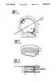
- FIG. 1is a front perspective view of an exemplary prior art code wheel assembly
- FIG. 2is a partial view of the face of the code wheel of FIG. 1;
- FIG. 3is a partial section view of the light source and receptor apparatus of FIG. 1;
- FIG. 4is an enlarged partial view of the code wheel and receptor apparatus of FIG. 1;
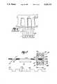
- FIG. 5is a side elevation of the apparatus of a prior art code wheel and detector assembly and a corresponding output wave form
- FIG. 6is a plan view of one embodiment of the prior art detector of FIG. 5;
- FIG. 7is a side elevation of the apparatus of the present invention for an equal density code wheel and a corresponding output wave form
- FIG. 8is a plan view of an embodiment of the detector of FIG. 7.
- FIG. 9is a plan view of a second embodiment of the detector of FIG. 7.
- FIGS. 1-6relate most particularly to the Machida application and the subject matter therein.
- FIG. 5is representative of the prior art as disclosed in the Machida application.
- an encoder module 1provides a collimated light beam and has light detectors 7 to receive the light beam after modulation by a code wheel 3.
- a light emitting diode (LED) 9provides light having a preferred wave length of approximately 700 nanometers; however, any frequency of electromagnetic radiation having a wave length substantially shorter than the relevant dimensions of the encoder may be utilized. For example, infrared light is commonly used.
- An emitter lensis positioned to transmit the light from the LED 9.
- the code wheel 3 of FIG. 2is concentrically mounted on a shaft 5 to rotate with the shaft and modulate the light beam with an optical track 17.
- the track 17has alternating light-transmissive sections or windows 13 and non-light-transmissive sections or spokes 15 of a unit width equal to the width of a window.
- One transmissive section and one non-transmissive sectionmake up one pitch of the code wheel.
- the alternating sections 13, 15block or transmit light from the LED, thereby illuminating or blocking light passing to the photodetectors.
- the code wheelhas a data track containing 500 transmissive sections and an equal number of nontransmissive sections. These sections are trapezoidal since they are located immediately adjacent to one another.
- An exemplary nominal width of each transmissive sectionis 62 microns, and a radial length of each section is 750 microns.
- the code wheelis preferably made of a durable, optically opaque material, such as stainless steel, and has a diameter of approximately 22 millimeters.
- Transmissive sectionsmay comprise holes masked and etched through the disk.
- a group of four light detectors 110a, 110b, 112, 114has approximately the same size and shape as one transmissive section and one non-transmissive section on the code wheel.
- Individual detectors 110a, 110b, 112, 114have a trapezoidal shape with an exemplary maximum width of 48 microns, a minimum width of approximately 45 microns with a gap of about 8 microns between the individual light detectors.
- the light detectorspreferably comprise photodiodes fabricated on a semiconductor chip using standard bipolar semiconductor technology. As illustrated in FIG. 4, a group of light detectors are placed in a one-dimensional array as close to one another as the bipolar semiconductor technology will allow.
- Dummy photodiodes 10 and 12are located on each side of the array to minimize the effect of stray light on the functioning light detectors 110a, 110b, 112, 114.
- the photodiodesare arranged in an arc having the same radius as the code track on the code wheel.
- the encodercomprises a code wheel 103 and an LED assembly or illumination means 100 in a photodetector assembly or photodetector means 108.
- the code wheel 3includes an index window 116 formed by removing a spoke 115 from wheel 103, resulting in creation of a window 116 having a length 118 of three units.
- the LED assembly 100is preferably mounted in a single housing 100' having a length 101 of two units, that is, less than the length 118.
- the LED assemblyincludes a first LED 102, a second LED 104, and third LED 106, although a single LED having a collimating lens may be used.
- a collimating lensis used to insure that light is directed straight at the photodetector assembly 108.
- the photodetector assembly 108similarly is preferably encapsulated in a single housing 109 having a 2-unit length 101.
- the housingmay comprise a single integrated circuit.
- the photodetector assemblyincludes a first photodetector 110, a second photodetector 112, and a third photodetector 114.
- the first photodetector 110has a unit width and is located between the two other photodetectors 112 and 114, which are each fabricated with the one-half unit width. Thus, the combined width of the three photodetectors is two units.
- the length 118 of the index windowis 1.5 times the length of the LED and photodetector assemblies.
- the photodetector assemblymay be constructed in the form of a single integrated circuit having a flat, generally rectangular body 128 divided into four separate photodetectors 110a, 110b, 112, 114, each having a half-unit width.
- the center photodetectors 110a and 110bare wired together to produce a single output line 132.
- these two center photodetectors 110a, 110bform a unit width center photodetector panel.
- Photodetectors 112, 114are each a half-unit wide.
- the outer pair of photodetectorsare also connected together by a single output line 134.
- the output lines 132, 134 from the photodetectorsare connected to a buffer circuit 136 in a known manner which produces a single output on line 138.
- FIG. 5illustrates the wave form output of the photodetector assembly 108 of FIG. 6.
- This wave form 120includes a low level index pulse 122 separated from the trailing edge 154 and the leading edge 156 of the adjacent pulses by approximately three times the unit pulse width.
- the output 138 from buffer 136is obtained by summing the outputs from detectors 112, 114 and comparing it to the sum of the outputs of detectors 110a and 110b.
- the relevant logic equationsare that the output 138 is equal to a logic 1 if the sum of the output of photodetectors 112, 114 is greater than the sum of the outputs from photodetectors 110a, 110b.
- the output 138is a logic 0 if the sum of the outputs of photodetectors 110a, 110b is greater than the sum of the outputs of the photodetectors 112, 114.
- an ambiguous stateresults if a code wheel of half density is used. For example, if all four photodetectors are illuminated, then each produces an identical output. The sum of the output of the photodetectors 112 and 114 equals the sum of the outputs of photodetectors 110a and 110b. Thus, under the logic equations, the output 138 is indeterminate. Similarly, he output of photodetectors 112, 114 equals the sum of the output of photodetectors 110a, 110b. Output 138 is again in an indeterminate state.
- the apparatus of FIG. 7comprising a code wheel 203, an LED assembly or illumination means 200 and a photodetector assembly or photodetector means 208.
- the code wheel 203includes an index window 216 formed by removing a spoke 215 from wheel 203, resulting in creation of a window 216, having a length 218 of three units.
- the LED assembly 200is preferably mounted in a single housing 200', having a length 201 of two units, that is, less then the length 218.
- the LED assemblyincludes an LED 202, and a collimating lens 204.
- a collimating lensis used to insure that light is directed straight at the photodetector assembly 208.
- three LEDs, one opposite each photodetectormay be used.
- the photodetector assembly 208is preferably encapsulated in a single housing 209 in a manner similar to the prior art.
- the housingpreferably has a two unit length 201. Furthermore, the housing may comprise a single integrated circuit.
- the photodetector assemblyincludes a principal photodetector 210 and two secondary photodetectors 212 and 214.
- the principal photodetector 210has a unit width; the secondary photodetectors have a half unit width. Thus, the combined width of the three photodetectors is two units.
- the principal photodetectorhas a first length and is located between the two secondary photodetectors 212 and 214.
- the principal photodetectorhas a first length; the secondary photodetectors have a second length, the second length being less than the first length.
- the photodetector assemblymay be constructed in a form similar to that of the prior art as shown in FIG. 6.
- the photodetector assemblymay be constructed in the form of the single integrated circuit, having a flat generally rectangular body 228 divided into three separate photodetectors 210, 212, 214.
- the principal photodetectorcan be made from two photodetectors, both identical and having a half-unit width and a first length. By wiring the two photodetectors together, they form a principal photodetector panel.
- the principal photodetector 210is one unit wide.
- the secondary photodetectors 212, 214are each a half-unit wide.
- the outer pair of photodetectorsare also connected together by a single output line 234.
- the principal photodetectorhas an output line 232.
- the output lines 232, 234 from the photodetectorsare connected to a buffer circuit 236 in a known manner which produces a single output on line 238.
- the output from a photodetectoris a function of the illuminated area of the photodetector. Because the principal photodetector has an area larger than the combined area of the secondary photodetectors, the output signal 232 from the principal photodetector will be greater than the output signal 234 from the secondary photodetectors when all of the photodetectors are illuminated. Preferably the area of the principal photodetector is 4 to 20% larger than the combined area of the pair of secondary photodetectors. For a 16% larger area, the principal photodetector typically has an output current of 1.2 microamps for typical photodetector geometries. Similarly the secondary photodetectors each produce an output signal of 0.5 microamps. Therefore, for a totally illuminated condition, the principal output signal 232 of 1.2 microamps is greater than the secondary output signal 234 of 1.0 microamps. Hence in an all light condition the principal photodetector 210 is favored.
- secondary output signal 234is biased by bias circuit 235 which produces a current offset of 0.1 microamps.
- the means for producing this bias currentis well-known to those skilled in the art. This current offset will be present regardless of the state of illumination of the secondary photodetectors.
- the current offset of the secondary photodetectorsmust be less than the geometric offset of the principal photodetector.
- the current offsetis 0.1 microamps; the geometric offset is 0.2 microamps.
- the logic equations for this embodimentare similar to the logic equations for the prior art of FIG. 6.
- the sum of the outputs from the secondary photodetectorsis compared to the output from the principal photodetector.
- the output 238is a logic zero when the output from the principal photodetector is greater than the sum of the outputs from the principal photodetector.
- the output 238is a logic one when the sum of the outputs from the secondary photodetectors is greater than the output from the principal photodetector.
- this photodetectordoes not have an ambiguous state when all photodetectors are illuminated or occurs.
- the principal photodetectorwhen all photodetectors are illuminated, the principal photodetector produces a greater current then the sum of the secondary photodetectors because of the geometric offset created by the larger area of the principal photodetector.
- the principal photodetectorproduces an output signal having a 1.2 microamp current.
- the secondary photodetectors and the bias circuithave an output current totalling microamps. Therefore, in an all light condition, because the output from the principal photodetector 210 is greater than the sum of the outputs from the secondary photodetectors 212, 214, the output 238 will be a logic zero.
- the output current from the principal photodetectoris 50.5 nanoamps.
- the output from the secondary photodetectors and the bias circuitis 150 nanoamps. Because the output from the secondary photodetectors and the bias circuit is greater than the output from the principal photodetectors, output 238 is a logic one. Thus, in this invention, there is no ambiguous output for all light or all dark illumination conditions.
- the photodetectorfunctions as an edge detector. As the spoke moves across the photodetectors, the principal and secondary outputs change as the amount of illumination changes. When the principal output signal changes from being less than the secondary output signal to being greater than the secondary output signal or vice versa, the logic value of the output 238 correspondingly changes value. Because the edge of the window or spoke creates the change in illumination of the photodetectors, the switch of logic state of output 238 occurs when the edge is at a defined location. The invention causes the switch in logic states to properly occur because the ambiguity in the logic equations has been resolved.
- FIG. 9shows an alternative embodiment of the present invention.
- the photodetector assembly 303may be constructed in the form of the single integrated circuit, having a flat generally rectangular body 328 divided into three separate photodetectors 310, 312, 314.
- the principal photodetector 310 and the secondary photodetector 312, 314have a unit length.
- the principal photodetectorhas a width 330
- the secondary photodetector 312has a width 334
- the other secondary photodetector 314has a width 332.
- the width 330is greater than the sum of the widths 332, 334.
- the width 332is equal to the width 334.
- the principal photodetectorhas an area larger than the combined area of the secondary photodetectors.
- the widthsare adjusted to provide a geometric offset as discussed above for the embodiment of FIG. 8.
- the circuitry and the combining of output signals from the photodetectors in this embodimentis identical to that disclosed for the embodiment shown in FIG. 8.
- the area of the principal photodetectoris greater than the area of the secondary photodetectors and, thus, the principal photodetector will produce a greater output current than the secondary photodetectors, when the photodetectors are fully illuminated.
- a larger effective area for the principal photodetectorcan be achieved by means other than physical area.
- the LED opposite the principal photodetector 110can be brighter than the sum of the outputs of LEDs 204, 206 opposite the secondary photodetector, so that in a fully illuminated condition, the output current from the principal photodetector is greater than the output from the secondary photodetectors.
- a maskcan be placed over the secondary photodetectors to filter some of the light from the LED.
- the code wheelis referred to as being located “between” the light source and the photodetectors.
- the term “between”also extends to an arrangement in which both the light source and the photodetectors are located on the same side of the code wheel.
- the code wheelmay comprise a solid disk having plural reflective regions, serving as "windows,” interleaved with opaque, nonreflected "spokes,” so that light from the light source reflects off the reflective windows and into the photodetectors.
- the three unit wide window discussed hereinis functionally the same as a missing spoke.
Landscapes
- Physics & Mathematics (AREA)
- General Physics & Mathematics (AREA)
- Optical Transform (AREA)
Abstract
Description
Claims (12)
Priority Applications (2)
| Application Number | Priority Date | Filing Date | Title |
|---|---|---|---|
| US07/787,528US5241172A (en) | 1991-11-04 | 1991-11-04 | Variable pitch position encoder |
| JP4319339AJPH05223598A (en) | 1991-11-04 | 1992-11-04 | Optical type encoder |
Applications Claiming Priority (1)
| Application Number | Priority Date | Filing Date | Title |
|---|---|---|---|
| US07/787,528US5241172A (en) | 1991-11-04 | 1991-11-04 | Variable pitch position encoder |
Publications (1)
| Publication Number | Publication Date |
|---|---|
| US5241172Atrue US5241172A (en) | 1993-08-31 |
Family
ID=25141781
Family Applications (1)
| Application Number | Title | Priority Date | Filing Date |
|---|---|---|---|
| US07/787,528Expired - LifetimeUS5241172A (en) | 1991-11-04 | 1991-11-04 | Variable pitch position encoder |
Country Status (2)
| Country | Link |
|---|---|
| US (1) | US5241172A (en) |
| JP (1) | JPH05223598A (en) |
Cited By (37)
| Publication number | Priority date | Publication date | Assignee | Title |
|---|---|---|---|---|
| US5406077A (en)* | 1993-03-30 | 1995-04-11 | Mitsubishi Denki Kabushiki Kaisha | Absolute value encoder and an output correction method of absolute value encoder having a signal processing/control circuit |
| US5596189A (en)* | 1991-05-02 | 1997-01-21 | Orton; Paul A. | Measuring system for determining transverse deflection of a rotary shaft |
| GB2309519A (en)* | 1996-01-26 | 1997-07-30 | Asahi Optical Co Ltd | Encoder for exposure controlling device of a camera |
| US5781817A (en)* | 1996-01-26 | 1998-07-14 | Asahi Kogaku Kogyo Kabushiki Kaisha | Exposure controlling device and encoder for camera |
| WO1999008074A1 (en)* | 1997-08-07 | 1999-02-18 | Dr. Johannes Heidenhain Gmbh | Scanning unit for an optical position measuring device |
| US5982551A (en)* | 1998-09-25 | 1999-11-09 | Wang; Ching-Shun | Optical encoder wheel with split lens ring |
| US6396052B1 (en) | 2000-04-07 | 2002-05-28 | Lexmark International, Inc. | High precision analog encoder system |
| US6653619B2 (en) | 2000-09-15 | 2003-11-25 | Agilent Technologies, Inc. | Optical motion encoder with a reflective member allowing the light source and sensor to be on the same side |
| US20040027117A1 (en)* | 2002-04-29 | 2004-02-12 | Siemens Aktiengesellschaft | Drive unit |
| US20040165277A1 (en)* | 2003-02-25 | 2004-08-26 | Ng Peng Yam | Single lens multiple light source device |
| US20050068773A1 (en)* | 2000-08-17 | 2005-03-31 | Kee-Yean Ng | Optical encoder module |
| US20050236561A1 (en)* | 2004-04-22 | 2005-10-27 | Hin Chee C | Photodetector array arrangement for optical encoders |
| US20060022126A1 (en)* | 2004-08-02 | 2006-02-02 | Chong Chee K | Photodetector array and codewheel configuration for flexible optical encoder resolution |
| US20060043271A1 (en)* | 2004-08-25 | 2006-03-02 | Chin Yee L | Optical encoding that utilizes total internal reflection |
| US7023363B1 (en) | 2005-02-17 | 2006-04-04 | Saiful Bahari Saidan | Position encoding using impedance comparison |
| US20060214015A1 (en)* | 2005-03-22 | 2006-09-28 | Miura Co., Ltd. | Damper position adjusting device and combustion apparatus equipped with the same |
| US20060284061A1 (en)* | 2005-06-17 | 2006-12-21 | Yeoh Theng H | System and method for optical encoding on two opposed surfaces of a pattern medium |
| US20070045526A1 (en)* | 2005-08-31 | 2007-03-01 | Saidan Saiful B B | Optical encoder with integrated index channel |
| US20080100569A1 (en)* | 2006-11-01 | 2008-05-01 | Chee Foo Lum | Optical jog wheel |
| US20080111062A1 (en)* | 2006-11-09 | 2008-05-15 | Weng Fei Wong | Coding element with integrated limit switch |
| US20080111061A1 (en)* | 2006-11-09 | 2008-05-15 | Weng Fei Wong | Encoder with a combined position and index track |
| US20080156973A1 (en)* | 2006-12-29 | 2008-07-03 | Weng Fei Wong | Photosensor array for optical encoder |
| US20080203283A1 (en)* | 2007-02-23 | 2008-08-28 | Yee Loong Chin | Optical encoder with detector lens |
| US20090090851A1 (en)* | 2007-10-07 | 2009-04-09 | Weng Fei Wong | Shaft-mounted detector for optical encoder |
| US20090152452A1 (en)* | 2007-12-18 | 2009-06-18 | Avago Technologies Ecbu Ip (Singapore) Pte. Ltd. | Reflective multi-turn encoder |
| US20100207324A1 (en)* | 2003-09-05 | 2010-08-19 | Bally Gaming International, Inc. | Systems, methods, and devices for monitoring card games, such as baccarat |
| US20110139971A1 (en)* | 2009-12-10 | 2011-06-16 | Lockheed Martin Corporation | Rotary position encoder |
| US20110147572A1 (en)* | 2009-12-17 | 2011-06-23 | Canon Kabushiki Kaisha | Rotary encoder and rotation mechanism including the same |
| DE102012202138A1 (en) | 2011-02-15 | 2012-08-16 | Avago Technologies Ecbu Ip (Singapore) Pte. Ltd. | Three-channel encoder that uses a single optical track |
| US8342932B2 (en) | 2005-09-12 | 2013-01-01 | Bally Gaming, Inc. | Systems, methods and articles to facilitate playing card games with intermediary playing card receiver |
| US20130229138A1 (en)* | 2010-11-08 | 2013-09-05 | Kabushiki Kaisha Yaskawa Denki | Reflection encoder, servo motor, and servo unit |
| US8550464B2 (en) | 2005-09-12 | 2013-10-08 | Bally Gaming, Inc. | Systems, methods and articles to facilitate playing card games with selectable odds |
| DE102014100172A1 (en) | 2013-01-09 | 2014-07-10 | Avago Technologies General Ip (Singapore) Pte. Ltd. | Single track three-channel encoder with differential index |
| US8847144B2 (en) | 2011-08-08 | 2014-09-30 | Avago Technologies General Ip (Singapore) Pte. Ltd. | Enhanced optical reflective encoder |
| US8920236B2 (en) | 2007-11-02 | 2014-12-30 | Bally Gaming, Inc. | Game related systems, methods, and articles that combine virtual and physical elements |
| US9339723B2 (en) | 2007-06-06 | 2016-05-17 | Bally Gaming, Inc. | Casino card handling system with game play feed to mobile device |
| US20230122652A1 (en)* | 2021-10-18 | 2023-04-20 | Insulet Corporation | Flexible linkage for positive displacement pumps |
Citations (7)
| Publication number | Priority date | Publication date | Assignee | Title |
|---|---|---|---|---|
| US4259570A (en)* | 1978-11-27 | 1981-03-31 | Hewlett-Packard Company | Optical comparator |
| US4266125A (en)* | 1978-12-21 | 1981-05-05 | Hewlett-Packard Company | Optical shaft angle encoder |
| US4423958A (en)* | 1980-03-20 | 1984-01-03 | Dr. Johannes Heidenhain Gmbh | Test apparatus for digital photoelectric length or angle measuring instrument |
| US4451731A (en)* | 1981-08-10 | 1984-05-29 | Hewlett-Packard Company | Apparatus and method for modulating light to generate an index pulse |
| US4691101A (en)* | 1985-06-19 | 1987-09-01 | Hewlett-Packard Company | Optical positional encoder comprising immediately adjacent detectors |
| US4963733A (en)* | 1989-01-09 | 1990-10-16 | Trj & Company | Incremental encoder |
| US4988865A (en)* | 1988-03-22 | 1991-01-29 | Frankl & Kirchner Gmbh & Co Kg Fabrik Fur Elektromotoren U. Elektrische Apparate | Device for determining the angular position of the drive shaft in a sewing machine |
- 1991
- 1991-11-04USUS07/787,528patent/US5241172A/ennot_activeExpired - Lifetime
- 1992
- 1992-11-04JPJP4319339Apatent/JPH05223598A/enactivePending
Patent Citations (7)
| Publication number | Priority date | Publication date | Assignee | Title |
|---|---|---|---|---|
| US4259570A (en)* | 1978-11-27 | 1981-03-31 | Hewlett-Packard Company | Optical comparator |
| US4266125A (en)* | 1978-12-21 | 1981-05-05 | Hewlett-Packard Company | Optical shaft angle encoder |
| US4423958A (en)* | 1980-03-20 | 1984-01-03 | Dr. Johannes Heidenhain Gmbh | Test apparatus for digital photoelectric length or angle measuring instrument |
| US4451731A (en)* | 1981-08-10 | 1984-05-29 | Hewlett-Packard Company | Apparatus and method for modulating light to generate an index pulse |
| US4691101A (en)* | 1985-06-19 | 1987-09-01 | Hewlett-Packard Company | Optical positional encoder comprising immediately adjacent detectors |
| US4988865A (en)* | 1988-03-22 | 1991-01-29 | Frankl & Kirchner Gmbh & Co Kg Fabrik Fur Elektromotoren U. Elektrische Apparate | Device for determining the angular position of the drive shaft in a sewing machine |
| US4963733A (en)* | 1989-01-09 | 1990-10-16 | Trj & Company | Incremental encoder |
Cited By (77)
| Publication number | Priority date | Publication date | Assignee | Title |
|---|---|---|---|---|
| US5596189A (en)* | 1991-05-02 | 1997-01-21 | Orton; Paul A. | Measuring system for determining transverse deflection of a rotary shaft |
| US5406077A (en)* | 1993-03-30 | 1995-04-11 | Mitsubishi Denki Kabushiki Kaisha | Absolute value encoder and an output correction method of absolute value encoder having a signal processing/control circuit |
| GB2309519B (en)* | 1996-01-26 | 1999-12-15 | Asahi Optical Co Ltd | Encoder for camera |
| US5781817A (en)* | 1996-01-26 | 1998-07-14 | Asahi Kogaku Kogyo Kabushiki Kaisha | Exposure controlling device and encoder for camera |
| GB2309519A (en)* | 1996-01-26 | 1997-07-30 | Asahi Optical Co Ltd | Encoder for exposure controlling device of a camera |
| WO1999008074A1 (en)* | 1997-08-07 | 1999-02-18 | Dr. Johannes Heidenhain Gmbh | Scanning unit for an optical position measuring device |
| US6392224B1 (en)* | 1997-08-07 | 2002-05-21 | Dr. Johannes Heidenhain Gmbh | Scanning unit for an optical position measuring device |
| DE19833439B4 (en)* | 1997-08-07 | 2014-08-28 | Dr. Johannes Heidenhain Gmbh | Optical position measuring device |
| US5982551A (en)* | 1998-09-25 | 1999-11-09 | Wang; Ching-Shun | Optical encoder wheel with split lens ring |
| US6396052B1 (en) | 2000-04-07 | 2002-05-28 | Lexmark International, Inc. | High precision analog encoder system |
| US20050068773A1 (en)* | 2000-08-17 | 2005-03-31 | Kee-Yean Ng | Optical encoder module |
| US7279674B2 (en)* | 2000-08-17 | 2007-10-09 | Avago Technologies Ecbu Ip (Singapore) Pte Ltd | Optical encoder module |
| US6653619B2 (en) | 2000-09-15 | 2003-11-25 | Agilent Technologies, Inc. | Optical motion encoder with a reflective member allowing the light source and sensor to be on the same side |
| US7109614B2 (en)* | 2002-04-29 | 2006-09-19 | Siemens Aktiengesellschaft | Drive unit for determining a rotation position and/or rotation speed of a drive shaft |
| US20040027117A1 (en)* | 2002-04-29 | 2004-02-12 | Siemens Aktiengesellschaft | Drive unit |
| US7302181B2 (en) | 2003-02-25 | 2007-11-27 | Avago Technologies Ecbu Ip (Singapore) Pte. Ltd. | Single lens multiple light source device |
| US20040165277A1 (en)* | 2003-02-25 | 2004-08-26 | Ng Peng Yam | Single lens multiple light source device |
| US20100207324A1 (en)* | 2003-09-05 | 2010-08-19 | Bally Gaming International, Inc. | Systems, methods, and devices for monitoring card games, such as baccarat |
| US8485907B2 (en) | 2003-09-05 | 2013-07-16 | Bally Gaming, Inc. | Systems, methods, and devices for monitoring card games, such as Baccarat |
| US20050236561A1 (en)* | 2004-04-22 | 2005-10-27 | Hin Chee C | Photodetector array arrangement for optical encoders |
| US7126108B2 (en) | 2004-04-22 | 2006-10-24 | Avago Technologies Ecbu Ip (Singapore) Pte. Ltd. | Photodetector array arrangement for optical encoders |
| US20080245956A1 (en)* | 2004-08-02 | 2008-10-09 | Chee Keong Chong | Photodetector array and codewheel configuration for flexible optical encoder resolution |
| US20060022126A1 (en)* | 2004-08-02 | 2006-02-02 | Chong Chee K | Photodetector array and codewheel configuration for flexible optical encoder resolution |
| US7638756B2 (en) | 2004-08-02 | 2009-12-29 | Avago Technologies Ecbu Ip (Singapore) Pte. Ltd. | Photodetector array and codewheel configuration for flexible optical encoder resolution |
| US7449675B2 (en) | 2004-08-02 | 2008-11-11 | Avago Technologies Ecbu Ip (Singapore) Pte. Ltd. | Photodetector array and codewheel configuration for flexible optical encoder resolution |
| US7145127B2 (en) | 2004-08-25 | 2006-12-05 | Avago Technologies Ecbu Ip (Singapore) Pte. Ltd. | Optical encoding that utilizes total internal reflection |
| US20060043271A1 (en)* | 2004-08-25 | 2006-03-02 | Chin Yee L | Optical encoding that utilizes total internal reflection |
| US7023363B1 (en) | 2005-02-17 | 2006-04-04 | Saiful Bahari Saidan | Position encoding using impedance comparison |
| US20060214015A1 (en)* | 2005-03-22 | 2006-09-28 | Miura Co., Ltd. | Damper position adjusting device and combustion apparatus equipped with the same |
| US7348545B2 (en)* | 2005-06-17 | 2008-03-25 | Avago Technologies Ecbu Ip Pte Ltd | System and method for optical encoding on two opposed surfaces of a pattern medium |
| US20060284061A1 (en)* | 2005-06-17 | 2006-12-21 | Yeoh Theng H | System and method for optical encoding on two opposed surfaces of a pattern medium |
| US20070045526A1 (en)* | 2005-08-31 | 2007-03-01 | Saidan Saiful B B | Optical encoder with integrated index channel |
| CN1924527B (en)* | 2005-08-31 | 2010-10-27 | 安华高科技Ecbuip(新加坡)私人有限公司 | Optical encoder with integrated index channel |
| US7394061B2 (en)* | 2005-08-31 | 2008-07-01 | Avago Technologies Ecbu Pte Ltd | Optical encoder with integrated index channel |
| US8342932B2 (en) | 2005-09-12 | 2013-01-01 | Bally Gaming, Inc. | Systems, methods and articles to facilitate playing card games with intermediary playing card receiver |
| US8550464B2 (en) | 2005-09-12 | 2013-10-08 | Bally Gaming, Inc. | Systems, methods and articles to facilitate playing card games with selectable odds |
| US7675026B2 (en) | 2006-11-01 | 2010-03-09 | Avago Technologies Ecbu Ip (Singapore) Pte. Ltd. | Optical jog wheel with spiral coding element |
| US20080100569A1 (en)* | 2006-11-01 | 2008-05-01 | Chee Foo Lum | Optical jog wheel |
| US20080099669A1 (en)* | 2006-11-01 | 2008-05-01 | Chee Foo Lum | Optical jog wheel with spiral coding element |
| US8247758B2 (en) | 2006-11-01 | 2012-08-21 | Avago Technologies Ecbu Ip (Singapore) Pte. Ltd. | Optical jog wheel with spiral coding element |
| US7732756B2 (en) | 2006-11-01 | 2010-06-08 | Avago Technologies Ecbu Ip (Singapore) Pte. Ltd. | User navigation device with a code wheel and an encoder |
| US20100127162A1 (en)* | 2006-11-01 | 2010-05-27 | Avago Technologies Ecbu Ip (Singapore) Pte. Ltd. | Optical jog wheel with spiral coding element |
| US7400269B2 (en) | 2006-11-09 | 2008-07-15 | Avago Technologies Ecbu Ip Pte Ltd | Coding element with integrated limit switch |
| US7619209B2 (en) | 2006-11-09 | 2009-11-17 | Avago Technologies Ecbu Ip (Singapore) Pte. Ltd. | Encoder with a combined position and index track |
| US7619210B2 (en) | 2006-11-09 | 2009-11-17 | Avago Technologies Ecbu Ip (Singapore) Pte. Ltd. | Encoder with a combined position and index track |
| US20080251700A1 (en)* | 2006-11-09 | 2008-10-16 | Weng Fei Wong | Encoder with a combined position and index track |
| US20080251701A1 (en)* | 2006-11-09 | 2008-10-16 | Weng Fei Wong | Encoder with a combined position and index track |
| US7507950B2 (en)* | 2006-11-09 | 2009-03-24 | Avago Technologies Ecbu Ip (Singapore) Pte. Ltd. | Encoder with a combined position and index track |
| US20080111061A1 (en)* | 2006-11-09 | 2008-05-15 | Weng Fei Wong | Encoder with a combined position and index track |
| US20080111062A1 (en)* | 2006-11-09 | 2008-05-15 | Weng Fei Wong | Coding element with integrated limit switch |
| US20080156973A1 (en)* | 2006-12-29 | 2008-07-03 | Weng Fei Wong | Photosensor array for optical encoder |
| US20080203283A1 (en)* | 2007-02-23 | 2008-08-28 | Yee Loong Chin | Optical encoder with detector lens |
| US10504337B2 (en) | 2007-06-06 | 2019-12-10 | Bally Gaming, Inc. | Casino card handling system with game play feed |
| US10008076B2 (en) | 2007-06-06 | 2018-06-26 | Bally Gaming, Inc. | Casino card handling system with game play feed |
| US9659461B2 (en) | 2007-06-06 | 2017-05-23 | Bally Gaming, Inc. | Casino card handling system with game play feed to mobile device |
| US9339723B2 (en) | 2007-06-06 | 2016-05-17 | Bally Gaming, Inc. | Casino card handling system with game play feed to mobile device |
| US7557340B2 (en) | 2007-10-07 | 2009-07-07 | Avago Technologies Ecbu Ip (Singapore) Pte. Ltd. | Shaft-mounted detector for optical encoder having an aperture through the detector for receiving a rotary shaft of a motor |
| US9046387B2 (en) | 2007-10-07 | 2015-06-02 | Avago Technologies General Ip (Singapore) Pte. Ltd. | Shaft-mounted detector for optical encoder |
| US20090090851A1 (en)* | 2007-10-07 | 2009-04-09 | Weng Fei Wong | Shaft-mounted detector for optical encoder |
| DE102008050182A1 (en) | 2007-10-07 | 2010-07-29 | Avago Technologies Ecbu Ip (Singapore) Pte. Ltd. | Wave-mounted optical encoder detector |
| US20090236507A1 (en)* | 2007-10-07 | 2009-09-24 | Avago Technologies Ecbu Ip (Singapore) Pte. Ltd. | Shaft-mounted detector for optical encoder |
| US8920236B2 (en) | 2007-11-02 | 2014-12-30 | Bally Gaming, Inc. | Game related systems, methods, and articles that combine virtual and physical elements |
| US9613487B2 (en) | 2007-11-02 | 2017-04-04 | Bally Gaming, Inc. | Game related systems, methods, and articles that combine virtual and physical elements |
| US20090152452A1 (en)* | 2007-12-18 | 2009-06-18 | Avago Technologies Ecbu Ip (Singapore) Pte. Ltd. | Reflective multi-turn encoder |
| US8637804B2 (en)* | 2009-12-10 | 2014-01-28 | Lockheed Martin Corporation | Rotary position encoder |
| US20110139971A1 (en)* | 2009-12-10 | 2011-06-16 | Lockheed Martin Corporation | Rotary position encoder |
| US8476578B2 (en)* | 2009-12-17 | 2013-07-02 | Canon Kabushiki Kaisha | Rotary encoder and rotation mechanism including the same |
| US20110147572A1 (en)* | 2009-12-17 | 2011-06-23 | Canon Kabushiki Kaisha | Rotary encoder and rotation mechanism including the same |
| US8896256B2 (en)* | 2010-11-08 | 2014-11-25 | Kabushiki Kaisha Yaskawa Denki | Reflection encoder, servo motor, and servo unit |
| US20130229138A1 (en)* | 2010-11-08 | 2013-09-05 | Kabushiki Kaisha Yaskawa Denki | Reflection encoder, servo motor, and servo unit |
| US8525102B2 (en) | 2011-02-15 | 2013-09-03 | Avago Technologies General Ip (Singapore) Pte. Ltd. | Optical encoding system and optical encoder having an array of incremental photodiodes and an index photodiode for use in an optical encoding system |
| DE102012202138A1 (en) | 2011-02-15 | 2012-08-16 | Avago Technologies Ecbu Ip (Singapore) Pte. Ltd. | Three-channel encoder that uses a single optical track |
| DE102012202138B4 (en) | 2011-02-15 | 2023-09-28 | Avago Technologies International Sales Pte. Limited | Three-channel encoder that uses a single optical track |
| US8847144B2 (en) | 2011-08-08 | 2014-09-30 | Avago Technologies General Ip (Singapore) Pte. Ltd. | Enhanced optical reflective encoder |
| US9354087B2 (en) | 2013-01-09 | 2016-05-31 | Avago Technologies General Ip (Singapore) Pte. Ltd. | Single track three-channel encoder with differential index |
| DE102014100172A1 (en) | 2013-01-09 | 2014-07-10 | Avago Technologies General Ip (Singapore) Pte. Ltd. | Single track three-channel encoder with differential index |
| US20230122652A1 (en)* | 2021-10-18 | 2023-04-20 | Insulet Corporation | Flexible linkage for positive displacement pumps |
Also Published As
| Publication number | Publication date |
|---|---|
| JPH05223598A (en) | 1993-08-31 |
Similar Documents
| Publication | Publication Date | Title |
|---|---|---|
| US5241172A (en) | Variable pitch position encoder | |
| US5148020A (en) | Optical encoder with photodetectors of width equal to and one-half of code wheel's window and spoke width | |
| US8525102B2 (en) | Optical encoding system and optical encoder having an array of incremental photodiodes and an index photodiode for use in an optical encoding system | |
| US4691101A (en) | Optical positional encoder comprising immediately adjacent detectors | |
| EP0770850B1 (en) | Displacement information detection apparatus | |
| US4933673A (en) | Encoder | |
| US6175109B1 (en) | Encoder for providing incremental and absolute position data | |
| US4827123A (en) | Direction sensitive optical shaft encoder | |
| US4920259A (en) | Apparatus for producing a phase insensitive index pulse for motion encoders | |
| US20020038848A1 (en) | Optical motion encoder | |
| EP0419172B1 (en) | Optical encoders | |
| US20030085345A1 (en) | Multiple resolution photodiode sensor array for an optical encoder | |
| JP2006349678A (en) | System and method for optical encoding to two faces facing opposite direction of pattern medium | |
| US5130536A (en) | Optical rotary encoder with indexing | |
| US3749925A (en) | Opto-electronic transducer for position initialization of a linear motion mechanism | |
| US5069547A (en) | Multitrack multilevel sensing system with error detecting | |
| JP3262842B2 (en) | Optical encoder | |
| US7026604B2 (en) | Vernier-scaled high-resolution encoder | |
| US20050088667A1 (en) | Absolute position encoder requiring less than one encoding track per bit | |
| US6563108B1 (en) | System for tracking angular and linear motion | |
| US5013910A (en) | Shaft angle encoder with a symmetrical code wheel | |
| US20070126607A1 (en) | Interpolating encoder utilizing a frequency multiplier | |
| US9354087B2 (en) | Single track three-channel encoder with differential index | |
| US6822219B1 (en) | Timing device | |
| GB2294111A (en) | Steering column rotation sensor |
Legal Events
| Date | Code | Title | Description |
|---|---|---|---|
| AS | Assignment | Owner name:HEWLETT-PACKARD COMPANY, CALIFORNIA Free format text:ASSIGNMENT OF ASSIGNORS INTEREST.;ASSIGNOR:LUGARESI, THOMAS J.;REEL/FRAME:006255/0090 Effective date:19911101 | |
| STCF | Information on status: patent grant | Free format text:PATENTED CASE | |
| FEPP | Fee payment procedure | Free format text:PAYOR NUMBER ASSIGNED (ORIGINAL EVENT CODE: ASPN); ENTITY STATUS OF PATENT OWNER: LARGE ENTITY | |
| FPAY | Fee payment | Year of fee payment:4 | |
| AS | Assignment | Owner name:HEWLETT-PACKARD COMPANY, A DELAWARE CORPORATION, C Free format text:MERGER;ASSIGNOR:HEWLETT-PACKARD COMPANY, A CALIFORNIA CORPORATION;REEL/FRAME:010841/0649 Effective date:19980520 | |
| AS | Assignment | Owner name:AGILENT TECHNOLOGIES INC., CALIFORNIA Free format text:ASSIGNMENT OF ASSIGNORS INTEREST;ASSIGNOR:HEWLETT-PACKARD COMPANY, A DELAWARE CORPORATION;REEL/FRAME:010901/0336 Effective date:20000520 | |
| FPAY | Fee payment | Year of fee payment:8 | |
| FPAY | Fee payment | Year of fee payment:12 | |
| AS | Assignment | Owner name:AVAGO TECHNOLOGIES GENERAL IP PTE. LTD., SINGAPORE Free format text:ASSIGNMENT OF ASSIGNORS INTEREST;ASSIGNOR:AGILENT TECHNOLOGIES, INC.;REEL/FRAME:017207/0020 Effective date:20051201 | |
| AS | Assignment | Owner name:CITICORP NORTH AMERICA, INC.,DELAWARE Free format text:SECURITY AGREEMENT;ASSIGNOR:AVAGO TECHNOLOGIES GENERAL IP (SINGAPORE) PTE. LTD.;REEL/FRAME:017207/0882 Effective date:20051201 Owner name:CITICORP NORTH AMERICA, INC., DELAWARE Free format text:SECURITY AGREEMENT;ASSIGNOR:AVAGO TECHNOLOGIES GENERAL IP (SINGAPORE) PTE. LTD.;REEL/FRAME:017207/0882 Effective date:20051201 | |
| AS | Assignment | Owner name:AVAGO TECHNOLOGIES ECBU IP (SINGAPORE) PTE. LTD., SINGAPORE Free format text:ASSIGNMENT OF ASSIGNORS INTEREST;ASSIGNOR:AVAGO TECHNOLOGIES GENERAL IP (SINGAPORE) PTE. LTD.;REEL/FRAME:017675/0518 Effective date:20060127 Owner name:AVAGO TECHNOLOGIES ECBU IP (SINGAPORE) PTE. LTD.,S Free format text:ASSIGNMENT OF ASSIGNORS INTEREST;ASSIGNOR:AVAGO TECHNOLOGIES GENERAL IP (SINGAPORE) PTE. LTD.;REEL/FRAME:017675/0518 Effective date:20060127 Owner name:AVAGO TECHNOLOGIES ECBU IP (SINGAPORE) PTE. LTD., Free format text:ASSIGNMENT OF ASSIGNORS INTEREST;ASSIGNOR:AVAGO TECHNOLOGIES GENERAL IP (SINGAPORE) PTE. LTD.;REEL/FRAME:017675/0518 Effective date:20060127 | |
| AS | Assignment | Owner name:AVAGO TECHNOLOGIES GENERAL IP (SINGAPORE) PTE. LTD Free format text:CORRECTIVE ASSIGNMENT TO CORRECT THE NAME OF THE ASSIGNEE PREVIOUSLY RECORDED ON REEL 017207 FRAME 0020. ASSIGNOR(S) HEREBY CONFIRMS THE ASSIGNMENT;ASSIGNOR:AGILENT TECHNOLOGIES, INC.;REEL/FRAME:038633/0001 Effective date:20051201 |