US5240003A - Ultrasonic instrument with a micro motor having stator coils on a flexible circuit board - Google Patents
Ultrasonic instrument with a micro motor having stator coils on a flexible circuit boardDownload PDFInfo
- Publication number
- US5240003A US5240003AUS07/820,571US82057192AUS5240003AUS 5240003 AUS5240003 AUS 5240003AUS 82057192 AUS82057192 AUS 82057192AUS 5240003 AUS5240003 AUS 5240003A
- Authority
- US
- United States
- Prior art keywords
- instrument
- motor
- coil
- distal end
- sound waves
- Prior art date
- Legal status (The legal status is an assumption and is not a legal conclusion. Google has not performed a legal analysis and makes no representation as to the accuracy of the status listed.)
- Expired - Lifetime
Links
- 210000004204blood vesselAnatomy0.000claimsabstractdescription11
- 239000004020conductorSubstances0.000claimsdescription32
- 239000000463materialSubstances0.000claimsdescription22
- 230000000007visual effectEffects0.000claimsdescription11
- 239000012530fluidSubstances0.000claimsdescription8
- 230000001360synchronised effectEffects0.000claimsdescription8
- 238000002592echocardiographyMethods0.000claimsdescription5
- 239000002184metalSubstances0.000claimsdescription5
- 229910052751metalInorganic materials0.000claimsdescription5
- 238000000034methodMethods0.000description9
- 230000015572biosynthetic processEffects0.000description8
- 230000005855radiationEffects0.000description7
- 238000010276constructionMethods0.000description6
- 210000001367arteryAnatomy0.000description4
- 239000000523sampleSubstances0.000description4
- 238000002604ultrasonographyMethods0.000description4
- 238000010586diagramMethods0.000description3
- 239000007788liquidSubstances0.000description3
- 230000002966stenotic effectEffects0.000description3
- 230000003321amplificationEffects0.000description2
- 238000002399angioplastyMethods0.000description2
- 230000005540biological transmissionEffects0.000description2
- 238000003780insertionMethods0.000description2
- 230000037431insertionEffects0.000description2
- 238000011835investigationMethods0.000description2
- 238000003199nucleic acid amplification methodMethods0.000description2
- 239000002356single layerSubstances0.000description2
- 210000003462veinAnatomy0.000description2
- RYGMFSIKBFXOCR-UHFFFAOYSA-NCopperChemical compound[Cu]RYGMFSIKBFXOCR-UHFFFAOYSA-N0.000description1
- 238000001574biopsyMethods0.000description1
- 230000002301combined effectEffects0.000description1
- 239000002131composite materialSubstances0.000description1
- 229910052802copperInorganic materials0.000description1
- 239000010949copperSubstances0.000description1
- 210000004351coronary vesselAnatomy0.000description1
- 230000002596correlated effectEffects0.000description1
- 238000007872degassingMethods0.000description1
- 230000000694effectsEffects0.000description1
- 238000009760electrical discharge machiningMethods0.000description1
- 239000000835fiberSubstances0.000description1
- 238000003384imaging methodMethods0.000description1
- 230000000414obstructive effectEffects0.000description1
- 210000000056organAnatomy0.000description1
- 230000002093peripheral effectEffects0.000description1
- 229920000642polymerPolymers0.000description1
- 229910001220stainless steelInorganic materials0.000description1
- 239000010935stainless steelSubstances0.000description1
Images


Classifications
- A—HUMAN NECESSITIES
- A61—MEDICAL OR VETERINARY SCIENCE; HYGIENE
- A61B—DIAGNOSIS; SURGERY; IDENTIFICATION
- A61B8/00—Diagnosis using ultrasonic, sonic or infrasonic waves
- A61B8/12—Diagnosis using ultrasonic, sonic or infrasonic waves in body cavities or body tracts, e.g. by using catheters
- A—HUMAN NECESSITIES
- A61—MEDICAL OR VETERINARY SCIENCE; HYGIENE
- A61B—DIAGNOSIS; SURGERY; IDENTIFICATION
- A61B8/00—Diagnosis using ultrasonic, sonic or infrasonic waves
- A61B8/44—Constructional features of the ultrasonic, sonic or infrasonic diagnostic device
- A61B8/4444—Constructional features of the ultrasonic, sonic or infrasonic diagnostic device related to the probe
- A61B8/445—Details of catheter construction
- A—HUMAN NECESSITIES
- A61—MEDICAL OR VETERINARY SCIENCE; HYGIENE
- A61B—DIAGNOSIS; SURGERY; IDENTIFICATION
- A61B8/00—Diagnosis using ultrasonic, sonic or infrasonic waves
- A61B8/44—Constructional features of the ultrasonic, sonic or infrasonic diagnostic device
- A61B8/4444—Constructional features of the ultrasonic, sonic or infrasonic diagnostic device related to the probe
- A61B8/4461—Features of the scanning mechanism, e.g. for moving the transducer within the housing of the probe
- H—ELECTRICITY
- H02—GENERATION; CONVERSION OR DISTRIBUTION OF ELECTRIC POWER
- H02K—DYNAMO-ELECTRIC MACHINES
- H02K21/00—Synchronous motors having permanent magnets; Synchronous generators having permanent magnets
- H02K21/12—Synchronous motors having permanent magnets; Synchronous generators having permanent magnets with stationary armatures and rotating magnets
- H02K21/14—Synchronous motors having permanent magnets; Synchronous generators having permanent magnets with stationary armatures and rotating magnets with magnets rotating within the armatures
- H—ELECTRICITY
- H02—GENERATION; CONVERSION OR DISTRIBUTION OF ELECTRIC POWER
- H02K—DYNAMO-ELECTRIC MACHINES
- H02K3/00—Details of windings
- H02K3/04—Windings characterised by the conductor shape, form or construction, e.g. with bar conductors
- H02K3/26—Windings characterised by the conductor shape, form or construction, e.g. with bar conductors consisting of printed conductors
Definitions
- the present inventionrelates to a disposable intraluminal ultrasonic instrument which includes a catheter that has an ultrasonic sound wave transducer therein and a rotatable acoustic mirror for directing the sound waves outwardly into tissue and for receiving echo sounds and directing the echo sounds to the transducer for transmission to a visual display which displays an ultrasound picture of the tissue whereby one can determine the makeup or construction of the tissue, e.g., hard or soft.
- the present inventionalso relates to a micro motor used in such an instrument for rotating the acoustic mirror while the transducer provides sound waves to the acoustic mirror, the micro motor including flat stator coils mounted on a flexible circuit board.
- Rotation of the acoustic mirror within the tip or the tip portion having the mirror thereoncauses high frequency ultrasonic vibrations or sound waves emitted by the transducer to be emitted in different directions in a rotating path and the echoes of the sound waves are received by the acoustic mirror and thence by the transducer for transmission to a visual display whereby a picture can be created of the space around the catheter tip which may contain tissue or a stenotic buildup in a vessel.
- a problem with the instrument having the catheter described aboveis that the flexible drive shaft is fairly long, i.e., at least as long as the catheter itself. With this arrangement, it is difficult to supply a torsion free rotational force through the flexible drive shaft and to drive such a long flexible drive shaft for extended periods of time without malfunctioning.
- the present inventionprovides an intra-luminal ultrasonic instrument which does not have the problem of a long drive shaft by providing a micro motor of very small diameter in the catheter tip for driving a short drive shaft coupled to an acoustic mirror in the catheter tip, the motor having flat stator coils mounted on a flexible circuit board.
- This probeis utilized in examining organs and the like of a body.
- the probeis somewhat bulky in shape and size, is intended for insertion in body cavities, is not suitable for insertion inside veins and/or arteries and does not teach a motor having stator coils mounted on a flexible circuit board and having a diameter no greater than 3 millimeters mounted in a catheter tip.
- the Eggleton et al. U.S. Pat. No. 4,546,771discloses an acoustic microscope which has a transducer capable of producing and receiving high frequency acoustical beams and is positioned within a needle. This patent teaches using frequencies of 100 megahertz to 400 megahertz, and preferably frequencies of 500 megahertz or greater. These frequencies do not produce the necessary depth obtained with frequencies under 60 megahertz as utilized in the ultrasonic instrument of the present invention.
- This patentteaches the rotation of a rotating member by an arrangement of small electromagnets and permanent magnets attached to a needle.
- the needle in this patentcan only be inserted into tissue for biopsy procedures and is not adapted to be inserted into a blood vessel like the catheter tip of the present invention for evaluating space around the catheter tip and particularly, the tissue or stenotic buildup located around the catheter tip to a sufficient depth.
- a miniature stepper motor for use in timepieceis disclosed in the Knapen et al U.S. Pat. No. 4,908,808 assigned to Kinetron, B. V., The Netherlands.
- an ultrasonic instrumentfor the examination and/or treatment of blood vessels and similar lumina having a small transverse cross-section
- said instrumentincluding a catheter comprising a body and a tip having a distal end and a distal portion adapted to be introduced into a lumen and a proximal portion, said catheter holding a diameter no greater than 3 millimeters, a rotatable member in said tip, a micro motor in said tip having flat stator coils mounted on a flexible circuit board which is coiled into a cylinder and a rotor which is coupled to said rotatable member for rotating said rotatable member at a selected rpm, and means for generating and supplying sound waves to said rotatable member.
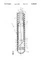
- FIG. 1is a cross-sectional view of a catheter tip of one embodiment of the disposable intra-luminal ultrasonic instrument constructed according to the teachings of the present invention.
- FIG. 2is a cross-sectional view of a catheter tip, similar to the view shown in FIG. 1, of another disposable intra-luminal ultrasonic instrument constructed according to the teachings of the present invention.
- FIG. 3is a cross-sectional view of a catheter tip, similar to the view shown in FIG. 1, of still another disposable intra-luminal ultrasonic instrument constructed according to the teachings of the present invention.
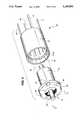
- FIG. 4is an exploded perspective view of a micro motor constructed according to the teachings of the present invention and having flat stator coils mounted on a flexible circuit board which is folded to a cylindrical shape.
- FIG. 5is an end view of the micro motor showing the output shaft end of the motor.
- FIG. 6is a longitudinal sectional view of the micro motor and is taken along line 6--6 of FIG. 5.
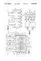
- FIG. 7is a plan view of the flexible circuit board with the flat frame stator coils mounted thereon before it is folded into a cylindrical shape, as shown in FIG. 4.
- FIG. 8is an enlarged fragmentary view, with portions broken away, of a portion of the circuit board and flat stator frame coils thereon shown in FIG. 7.
- FIG. 9is an equivalent circuit diagram of the electrical circuit of the stator coils shown in FIG. 7.
- FIG. 10is a mechanical schematic diagram of a cross-section of the two coil stator frame coils each including first and second branches with each branch having three legs one with the dots representing the current going in at the beginning of a first sinusoidal A.C. current entering the first branch of a first frame coil and of a second sinusoidal A.C. current entering the first branch of a second frame coil and the pluses indicating the first current coming out of the second branch of the first frame coil and the second current coming out of the second branch of the second frame coil.
- FIG. 11is a graph of the two phase sinusoidal current waves that are supplied to the two frame coils and through the two branches of each coil with the first phase entering the first branch of the first coil and then exiting out of the second branch of the first coil and the second phase entering the first branch of the second coil and exiting the second branch of the second coil and shows the mechanical effect of the configuration of the branches of the coils affecting the current density such that the effective current density from the three legs of each branch of each coil is represented by rectangles in FIG. 11.
- FIG. 1a catheter in the form of a thin flexible tube made of a suitable disposable material, e.g., a plastic material which forms part of a disposable intra-luminal ultrasonic instrument 1'.
- a suitable disposable materiale.g., a plastic material which forms part of a disposable intra-luminal ultrasonic instrument 1'.
- the outer diameter of the tube 1is not more than 2.7 millimeters and will be 0.62 millimeters, if the instrument is used for the examination and/or treatment of coronary vessels.
- the cap 2is made of a material which is transparent to ultrasonic radiation or sound waves when the instrument is provided with means for emitting ultrasonic radiation and for receiving the echoes of the emitted radiation. In any event, the cap 2 has a window for allowing this ultrasonic radiation to pass through the cap 2.
- a cylindrical micro motor 3is fastened in the distal end portion of the flexible tube 1 near the distal end of the tube 1 with the motor 3 being substantially co-axial with the axis of the catheter tube 1.
- the motor 3is placed at some distance from the distal end of the catheter tip 2'.
- a drive shaft 4extends distally from, is part of, and is driven by a motor 3.
- a rotatable elementwhich in this embodiment of the instrument 1' is a rotatable acoustic mirror 5, is mounted on the drive shaft 4 and has a mirror face 6 which lies in a plane that intersects the axis of the catheter tube 1 at an angle, as well as intersecting the axis of the drive shaft 4 of the motor 5.
- the mirror 5is rotatable with and on the drive shaft 4 during operation of the motor 3.
- the motor 3can be driven at an rpm between 600 and 4,000 rpm, e.g., 1,200 rpm, 1,800 rpm, 3,000 rpm or 3,600 rpm up to but not limited to 6,000 rpm.
- the rotational speed of the motoris correlated with a raster across a visual display (not shown) which is connected to the instrument 1'.
- a transducer 7is mounted within the distal end portion of the catheter tube 1 between the motor 3 and the mirror face 6 opposite or facing the mirror 6.
- the transducer 7has a central passageway or channel 8 therethrough through which the drive shaft 4 extends.
- Ultrasonic radiation at critically selected frequenciesis emitted by the transducer 7 at the mirror face 6 and reflected outwardly by the mirror face 6 in the direction generally driven by the arrows 9.
- This reflected bundle of radiation waves 9emerges from the catheter tip 2' via a window formed in or defined by the cap 2.
- the ultrasound waveis reflected by an obstacle, such as an artery wall, when the catheter tip is mounted in an artery, the reflected or echoed signal so generated will pass through the window, impinge upon the mirror face 6 and will be reflected to and received by the transducer 7.
- the reflected sound wavesare then supplied by the transducer 7 to a visual display where an ultrasound image of the space surrounding the catheter tip 2' and the material in that space can be displayed on a visual display, the raster of which is coordinated with the speed of rotation of the acoustic mirror 5.
- the operating frequency of the sound wavewill determine the depth of field of this ultrasonic imaging.
- the ultrasonic sound waves generated by the transducer 7are generated by a frequency that is not greater than 60 megahertz typically in the range of 15 and 45 megahertz, and preferably at approximately 30 megahertz for a good balance between depth of field and resolution.
- the motor 3is preferably a synchronous motor.
- the power supply for the motor 3can be outside the catheter tube 1 with the motor 3 being coupled to the power supply by a plurality of electrical wire conductors 10 and 11. These wire conductors 10 and 11 extend through the interior of the catheter tube 1 between the power supply and the motor 3 to which they are connected.
- the wire conductors 10can be a plurality of current supply wires 10 and the wire conductors 11 can be a plurality of current removal, ground or common, wires 11.
- electrical wire conductors 12 and 13 for transmitting the electrical signals to and from the transducer 7are received within and extend within catheter tube 1 between the transducer 7 on the distal end of the wire conductors 12 and 13 to an external drive and visual drive at the proximal drive of the wire conductors 12 and 13.
- the motor 3is mounted in the outer distal end portion 3" of the cap 2.
- the drive shaft 4extends proximally from the motor 3 and has the mirror 5 with mirror face 6 mounted thereon.
- the transducer 7is then mounted proximally of the mirror 5 opposite or facing the mirror face 6 within the flexible catheter tube 1 at the distal end thereof.
- end cap 2 and motor 3can be constructed as an integral unit and then mounted on the distal end of the flexible catheter tube 1 with the peripheral area of the cap 2 surrounding the mirror face 6 being of reduced thickness to enable the bundle of ultrasonic waves 9 reflected by the mirror face 6 to pass through the thin wall of the cap 2 and then permit reflected sound waves or echoes to come back through the thin wall of the cap 2.
- the electrical wire conductors 10 and 11 for the motor 3 and the electrical wire conductors 12 and 13 for the transducer 7again extend through the interior of the catheter tube 1, as in the embodiment of the instrument 1'shown in FIG. 1.
- FIG. 3there is illustrated therein still another embodiment 1"' of the disposable intra-luminal ultrasonic instrument of the present invention.
- the instrument 1"'has the transducer 7 mounted in a distal end portion 3"' of the cap 2.
- the motor 3is then mounted in the distal end portion of the catheter tube 1 much the same way as in the embodiment of the instrument 1' in FIG. 1.
- the mirror 5 with a mirror face 6, similar to the mirror 5 shown in FIG. 2is mounted between the transducer 7 and the motor 3 with the mirror face 6 facing the transducer 7 and the acoustic mirror 5 mounted on the drive shaft 4 of the motor 3.
- the mirror face 6faces proximally of the catheter tip 2
- the mirror face 6faces distally of the catheter tip 2
- a capillary tube 14extends through suitable aligned bores in the motor 3, the drive shaft 4, the mirror 5, the transducer 7 and the distal end of the distal end portion 3"' of the cap 2.
- a guidewirecan be inserted through the catheter tube 1, namely through the capillary tube 14 and protrude beyond the distal end of the distal end portion 3"' of the cap 2 for various known catheter procedures.
- an electronics switch 15such as an integrated circuit switch, which includes circuitry for amplifying the reflected or echoed signal received by the transducer 7 before such signal is transmitted via the wire conductors 12 and 13 to the visual display, can be provided.
- wire conductors 10 and 11 to the motor 3 and/or the wire conductors 12 and 13 to the transducer 7can be used jointly as means for determining the position of a catheter in a lumen, i.e., to determine the relative position of a catheter tip 2 with respect to the surrounding space.
- the wire conductors 12 and 13extend from the transducer 7 through, or are embedded in, the distal end portion of the catheter tube 1 and the wire conductors 10 and 11 extend proximally from the motor 3.
- the wire conductors 10 and 11are fixed in place in the distal end portion 3" of the catheter tip 2 and extend across or intersect the path of the emitted and reflected sound waves 9 and then through the distal end portion of the catheter tip portion 1 to the interior of the catheter tube 1.
- the portion of the wire conductors 10 and 11 in the vicinity of the mirror 5will be seen on the visual display so that the position of the catheter tip relative to the area of the lumen or blood vessel under investigation can be determined.
- the position of a portion of the wires 12 and 13 extending within the cap 2 in the vicinity of the mirror 5can be seen on the visual display for determining the orientation and location of the catheter tip 2" relative to the area of the lumen or blood vessel under investigation.
- This orientation methodis comparable to the orientation method described in Dutch Patent Application No. 89.01084, the disclosure of which is incorporated herein by reference.
- the mirror face 6is angled to the catheter axis in a manner as taught in Dutch Patent Application No. 87.00632.
- the transducer 7has a central channel 8 through which the drive shaft 4 can extend.
- the motor 3 of the intra-luminal ultrasonic instrument 1', 1" or 1"'is substantially cylindrical and has a length of less than approximately 6 millimeters, and a diameter of not more than approximately 2.4 millimeters, preferably not more than approximately 1 millimeter.
- devicessuch as the electrical wire conductors and their position can be utilized for determining the orientation of the catheter tip with respect to the surrounding space as taught in Dutch Patent Application No. 89.01084.
- the instrument 1', 1" or 1"'can be fitted in a suitable manner with devices to perform an examination inside the artery or vein after the examination has taken place, or even during the examination, to use an obstructive method, for example, for destroying plaque.
- the instrument 1', 1" or 1"'can, for example, be fitted with devices to perform the spark erosion method, as described in the Dutch Patent Application No. 87.00632.
- the instrument 1', 1" or 1"'with a balloon for use in a balloon dilatation method which is well known in the field of angioplasty.
- a suitable ballooncan be fastened around the catheter tip 2', 2", 2"', and a separate channel can be built in along the catheter tube 1 which is connected to the balloon for inflating it while operating it and thereafter allowing the balloon to deflate.
- a central channel or capillary tube 14can be provided for receiving a guidewire through the catheter tube 1 and the catheter tip 2"'.
- the space in the catheter tip 2', 2" or 2"' where the transducer 7 and mirror tip 5 are locatedis primarily filled with a liquid before operating the instrument 1', 1" or 1"' to ensure efficient acoustical operation of the instrument 1', 1" or 1"'.
- the above referred to spacecan be pre-evacuated using vacuum techniques and liquid can be sucked into the space via suitable channels. It is also possible to directly introduce liquid into the space via a filling tube so that the air or other gas present is expelled via suitable degassing channels in the catheter tube 1.
- the filling tubecan be a separate lumen in the catheter tube 1 or can be a small tube fitted along or in the catheter tube 1 itself and which can be pulled away after use.
- the integrated switch 15, as shown in FIG. 3,can be mounted in the catheter tip 2" of the instrument 1', 1" or 1"' adjacent the motor 3 and the transducer 7.
- This structural arrangementcan be provided to assist the amplification of the echo signal emitted by the transducer 7 before it is transmitted by the wire conductors 12 and 13 to the visual display; and such amplification allows certain structure in or on the catheter tube 1 to be omitted, e.g., the provision of a metal wire integrated with the catheter mantle, and working as a Faraday's cage, and concealed within the catheter tube 1 can be omitted.
- the instrument 1', 1" or 1"'works well with a French 5 catheter having a diameter of approximately 1.6 millimeters.
- the transducer 7is constructed, arranged and operated to emit sound waves at no more than 60 megahertz, typically somewhere between 15 and 45 megahertz, and in one preferred use of the instrument 1', 1" or 1"', at approximately 30 megahertz.
- the frequencies usedparticularly approximately 30 megahertz, results in an ultrasound picture having a depth of field of at least one-half inch (1/2") with good resolution so that the makeup or constitution, e.g., hard calcified or soft fatting material, of the tissue or stenotic buildup being investigated can be determined.
- the instruments 1', 1" or 1"'having the constructions described above with reference to FIGS. 1-3, are constructed in a simple and inexpensive manner which allows the instrument 1', 1" or 1"' to be a disposable instrument.
- FIGS. 4-6there is illustrated a micro motor 20 that is a flex print micro motor 20 particularly adapted for use in the intra-luminal ultrasonic instrument 1, 1', 1" or 1"' shown in FIGS. 1-3.
- the flex print micro motor 20includes a non-magnetic stator shell or housing 22. Mounted at one end, and typically the distal end 24 of the motor 20, is a first bearing 26 and within the stator housing 22 is mounted a similar second bearing 28 (FIG. 6).
- Each of the bearings 26 and 28has four side holes or notches 30 equidistantly spaced around the bearing 26,28 to provide for passage of fluid through the bearing 26 or 28 and then through the motor 20 and also to provide passage means for stator coil leads 31, 32, 33 and 34.
- a stainless steel rotor shaft 36is mounted in and between the bearings 26 and 28 with a distal end portion 38 of the shaft 36 extending outwardly from the motor 20.
- a rotor 39 of the motor 20has permanent magnets N and S, mounted thereon having opposite pluralities to provide a two pole rotor 39, as shown in FIG. 6.
- a flexible circuit board 40mounted adjacent the inner surface of the stator housing 22 is a flexible circuit board 40 having mounted thereon four flat stator coil branches 41, 42, 43 and 44 (FIG. 7).
- the geometry of the stator coil branches 41-44 printed on the flexible circuit board 40converts a two phase alternating current into a rotating sinusoidal current distribution thereby providing the necessary constant rotation and lower power dissipation required for the motor 20.
- an end cap 48having slots 50 therethrough through which the leads 31, 32, 33 and 34 can extend and a central passageway 52 therethrough which receives a tube 54 for supplying or withdrawing fluid from inside the motor 20 as shown in FIG. 6.
- Such fluidcan flow through the passageway 52 in the end cap 48, the notches 30 in one bearing 28, around the rotor 39 and through the notches 30 in the other bearing 26 when it is desired to deliver fluid to the vessel in which the motor 20 is located.
- fluidcan be withdrawn from the vessel via these passages to the tube 54 when, for example, a vacuum is placed on the tube 54.
- stator coil branches 41, 42, 43 and 44are integral with each other in one stator coil formation 60 with a first input lead 31 leading to three legs 61, 62 and 63 of the coil branch 41 of a first frame coil 64, the legs 61-63 being defined between internal notches 65 and 66 which are etched or otherwise formed through a sheet 70 of conductive, e.g., metal or metallic, material from which the coil formation 60 is formed and by a side edge 71 of the sheet 70 and a slot 72 extending from an upper edge 74 of the sheet 70 from which the leads 31-34 extend toward a lower edge 76, but only to a lower margin 78.
- conductivee.g., metal or metallic
- the circuit boardis made of KaptonTM and has a thickness of between 0.01 and 0.03 millimeters (mm).
- the sheet of conductive materialis preferably made of copper and has a thickness between 0.01 and 0.03 mm.
- Coil lead lengthbetween 1.0 and 10.0 mm.
- Coil lead widthbetween 0.1 and 0.5 mm.
- Coil legs widthbetween 0.02 and 10.0 mm.
- Coil width, W(FIG. 7): between 0.5 and 10.0 mm.
- Coil length, L(FIG. 8): between 0.1 and 10.0 mm.
- Coil formation lengthbetween 0.5 and 50.0 mm.
- Coil formation thicknessbetween 0.02 and 2.0 mm.
- Notch lengthbetween 0.1 and 10.0 mm.
- the leadsare approximately 0.20 mm wide and approximately 1.70 mm long.
- the coilsare approximately 0.625 mm wide and approximately 1.50 mm long.
- the slots and notchesare approximately 0.050 mm wide.
- the first and third legs of each coil branchare approximately 0.154 mm wide with the second or middle leg being approximately 0.217 mm.
- the coil formation 60has a length of approximately 2.65 mm.
- the circuit boardis approximately 0.015 mm thick and the sheet of conductive material is approximately 0.015 mm thick.
- a current I 0flows into the lead 31 through the legs 61-63 of the first coil branch 41 and in and along the lower margin 78 of the coil formation 60 to the third coil branch 43 which is interconnected by the margin 78 to the first coil branch 41 to form the first frame coil 64.
- the third coil branch 43is formed with three legs 81, 82 and 83 between two internal notches 84 and 86 and another two slots 88 and 90 which separate the second coil branch 42 from the third coil branch 43 and the third coil branch 43 from the fourth coil branch 44.
- the three leg coil branch 43is disposed opposite the first three leg coil branch 41 to form the frame coil 64 when the coil formation 60 is folded into a cylinder.
- a current I 1goes into the second lead 32 to the second coil branch 42 and through three legs 91, 92 and 93 which are formed between two internal notches 94 and 96 and the slots 72 and 88 which extend to the margin 78.
- the current I 1will then flow through the margin 78 to the fourth coil branch 44 and then flow through three legs 101, 102 and 103 formed between a side edge 104 of the coil formation 60, the slot 90 and two internal notches 106 and 108 to the lead 34.
- the second coil branch 42 and the fourth coil branch 44form a second frame coil 110 which is displaced 90 from the frame coil 64.
- the current densityis approximated to a sinusoidal distribution by splitting the two phase currents into three components, namely I 0 ,1 plus I 0 ,2 plus I 0 ,3 and I 1 ,1 plus I 1 ,2 plug I 1 ,3 as shown in FIG. 8.
- FIG. 9there is illustrated an equivalent circuit diagram of the stator coil circuits with two current generators I 1 and I 0 .
- the flow of the current I 1 and I 0 through the stator branch coil 41, 42, 43 and 44is shown.
- the design of the catheter-mounted micro motor 20 and the construction and operation of the frame coils 64 and 110provide a very small motor without brushes and of minimal complexity which is ideal for the space limitations in blood vessels.
- the first and second frame coilscombined yields a 2-pole, 2-phase synchronous motor with a permanent magnetic rotor.
- the rotor 39is preferably a composite magnet (an imbedded polymer sold by the company Kinetron at Tilburg, The Netherlands).
- the synchronous motor principlerequires for two magnetic poles and a set of two frame coil pairs where each coil produces a current density profile of a sinusoidal nature along the circumference.
- a single-layer flexprintis the preferred construction since it requires an overall thickness of 15 ⁇ m Cu+15 ⁇ m KaptonTM. This requires each coil branch to extend only over 1/4 of the circumference.
- the sinus curvenow has to be approximated over the angle range of 1/4 ⁇ to 3/4 ⁇ instead of 0 to ⁇ .
- the contribution of the areas 0-1/4 ⁇ and 3/4 ⁇ - ⁇is minimal.
- the separate coil branches 41-44are all interconnected at one side. This can only work if the sum of all incoming currents is zero. Hence a balanced current source must be used for each of the two phases.
- FIG. 10shows the arrangement of the coil branches 41 and 43 to form the frame coil 64 and the arrangement of the coil branches 42 and 44 to form the second frame coil 110. Also, there is shown the direction of the current flowing through the coil branches 41-44 at the beginning of the application of the two phases of current which are 90° out of phase from each other.
- FIG. 11there is illustrated the application of the sinusoidal two phase currents 120 and 130 with the phase current 130 being 90° out of phase from the phase current 120.
- the current density in the motoras a result of these two sinusoidal currents 120 and 130, out of phase by 90°, as affected by the mechanical construction and arrangement of the coil branches 41-44, and particularly the legs thereof, results in effective current densities in the form of pulses of current through each leg of each coil branch 41-44 of the two frame coils 64 and 110, as shown by the rectangles in FIG. 11.
- the combined effect of these effective coil densitiesis a generally sinusoidal, almost square, wave of electromagnetic force.
- This generally sinusoidal wave of electromagnetic forcehas few harmonics when compared to ideal two phase motors and, in particular, less second harmonics.
- a very high power output of 82%is obtained with the micro motor 20 of the present invention having stator coil branches 41-44 for two frame coils 64 and 110 formed on a printed circuit board.
Landscapes
- Health & Medical Sciences (AREA)
- Life Sciences & Earth Sciences (AREA)
- Engineering & Computer Science (AREA)
- Medical Informatics (AREA)
- Surgery (AREA)
- Pathology (AREA)
- Radiology & Medical Imaging (AREA)
- Biophysics (AREA)
- Biomedical Technology (AREA)
- Heart & Thoracic Surgery (AREA)
- Physics & Mathematics (AREA)
- Molecular Biology (AREA)
- Nuclear Medicine, Radiotherapy & Molecular Imaging (AREA)
- Animal Behavior & Ethology (AREA)
- General Health & Medical Sciences (AREA)
- Public Health (AREA)
- Veterinary Medicine (AREA)
- Power Engineering (AREA)
- Ultra Sonic Daignosis Equipment (AREA)
- Media Introduction/Drainage Providing Device (AREA)
Abstract
Description
______________________________________ Patentee U.S. Pat. No. ______________________________________ Yock 4,794,931 Pope et al 4,889,757 Prodian et al 4,917,097 Yock 5,000,185 Lum et al 5,003,238 Passafaro 5,010,886 Yock et al 5,029,588 ______________________________________
Claims (38)
Priority Applications (5)
| Application Number | Priority Date | Filing Date | Title |
|---|---|---|---|
| US07/820,571US5240003A (en) | 1989-10-16 | 1992-01-14 | Ultrasonic instrument with a micro motor having stator coils on a flexible circuit board |
| PCT/NL1992/000159WO1993005712A1 (en) | 1991-09-24 | 1992-09-17 | Ultrasonic instrument with a micro motor having stator coils on a flexible circuit board |
| DE69216842TDE69216842T2 (en) | 1991-09-24 | 1992-09-17 | MICROMOTOR WITH STAND WINDINGS IN THE FORM OF FLEXIBLE PRINTED CIRCUITS FOR AN ULTRASONIC INSTRUMENT |
| EP92920556AEP0605573B1 (en) | 1991-09-24 | 1992-09-17 | Ultrasonic instrument with a micro motor having stator coils on a flexible circuit board |
| US08/113,721US5375602A (en) | 1990-10-02 | 1993-08-27 | Ultrasonic instrument with a micro motor |
Applications Claiming Priority (5)
| Application Number | Priority Date | Filing Date | Title |
|---|---|---|---|
| NL8902559ANL8902559A (en) | 1989-10-16 | 1989-10-16 | INTRA-LUMINAL DEVICE. |
| NL8902559 | 1989-10-16 | ||
| US07/591,652US5176141A (en) | 1989-10-16 | 1990-10-02 | Disposable intra-luminal ultrasonic instrument |
| US76508491A | 1991-09-24 | 1991-09-24 | |
| US07/820,571US5240003A (en) | 1989-10-16 | 1992-01-14 | Ultrasonic instrument with a micro motor having stator coils on a flexible circuit board |
Related Parent Applications (1)
| Application Number | Title | Priority Date | Filing Date |
|---|---|---|---|
| US76508491AContinuation-In-Part | 1989-10-16 | 1991-09-24 |
Related Child Applications (1)
| Application Number | Title | Priority Date | Filing Date |
|---|---|---|---|
| US08/113,721ContinuationUS5375602A (en) | 1990-10-02 | 1993-08-27 | Ultrasonic instrument with a micro motor |
Publications (1)
| Publication Number | Publication Date |
|---|---|
| US5240003Atrue US5240003A (en) | 1993-08-31 |
Family
ID=27117559
Family Applications (2)
| Application Number | Title | Priority Date | Filing Date |
|---|---|---|---|
| US07/820,571Expired - LifetimeUS5240003A (en) | 1989-10-16 | 1992-01-14 | Ultrasonic instrument with a micro motor having stator coils on a flexible circuit board |
| US08/113,721Expired - LifetimeUS5375602A (en) | 1990-10-02 | 1993-08-27 | Ultrasonic instrument with a micro motor |
Family Applications After (1)
| Application Number | Title | Priority Date | Filing Date |
|---|---|---|---|
| US08/113,721Expired - LifetimeUS5375602A (en) | 1990-10-02 | 1993-08-27 | Ultrasonic instrument with a micro motor |
Country Status (4)
| Country | Link |
|---|---|
| US (2) | US5240003A (en) |
| EP (1) | EP0605573B1 (en) |
| DE (1) | DE69216842T2 (en) |
| WO (1) | WO1993005712A1 (en) |
Cited By (151)
| Publication number | Priority date | Publication date | Assignee | Title |
|---|---|---|---|---|
| US5375602A (en)* | 1990-10-02 | 1994-12-27 | Du-Med, B.V. | Ultrasonic instrument with a micro motor |
| US5392176A (en)* | 1993-07-26 | 1995-02-21 | Hewlett-Packard Company | Recording/reproducing device employing device housing and printed circuit board and electronics as structural and functional part of media drive motor and the media drive motor |
| US5406951A (en)* | 1993-10-15 | 1995-04-18 | Ten Hoff; Harm | Intra-luminal ultrasonic instrument |
| US5464016A (en)* | 1993-05-24 | 1995-11-07 | Boston Scientific Corporation | Medical acoustic imaging catheter and guidewire |
| US5485845A (en)* | 1995-05-04 | 1996-01-23 | Hewlett Packard Company | Rotary encoder for intravascular ultrasound catheter |
| US5507294A (en)* | 1995-01-17 | 1996-04-16 | Hewlett Packard Company | Ultrasound diagnostic probe having non-rotating acoustic imaging waveguide |
| US5509418A (en)* | 1995-01-17 | 1996-04-23 | Hewlett-Packard Co. | Ultrasound diagnostic probe having acoustically driven turbin |
| US5606975A (en)* | 1994-09-19 | 1997-03-04 | The Board Of Trustees Of The Leland Stanford Junior University | Forward viewing ultrasonic imaging catheter |
| DE19625649A1 (en)* | 1995-09-25 | 1997-03-27 | Hewlett Packard Co | Focusing ultrasound beam onto target region of object esp. for intravascular ultrasound imaging |
| US5635784A (en)* | 1995-02-13 | 1997-06-03 | Seale; Joseph B. | Bearingless ultrasound-sweep rotor |
| US5647367A (en)* | 1996-05-31 | 1997-07-15 | Hewlett-Packard Company | Scanning ultrasonic probe with locally-driven sweeping ultrasonic source |
| US5677579A (en)* | 1994-05-26 | 1997-10-14 | U.S. Philips Corporation | Electric micromotor with a slotted conductive body as the stator with insulating reinforcement in the slots thereof |
| US5699806A (en)* | 1996-10-01 | 1997-12-23 | Hewlett-Packard Company | Ultrasound system with nonuniform rotation corrector |
| US5701901A (en)* | 1996-11-26 | 1997-12-30 | Hewlett Packard Company | Ultrasonic probe with back and forth sweeping ultrasonic source |
| WO1998011823A1 (en) | 1996-09-20 | 1998-03-26 | Cardiovascular Imaging Systems, Inc. | Three-dimensional intraluminal ultrasound image reconstruction |
| US5779643A (en)* | 1996-11-26 | 1998-07-14 | Hewlett-Packard Company | Imaging guidewire with back and forth sweeping ultrasonic source |
| US5779644A (en)* | 1993-02-01 | 1998-07-14 | Endosonics Coporation | Ultrasound catheter probe |
| WO1998033430A3 (en)* | 1997-01-31 | 1998-11-26 | Acuson | Catheter-mounted, phased-array ultrasound transducer with improved imaging |
| US5842994A (en)* | 1997-07-02 | 1998-12-01 | Boston Scientific Technology, Inc. | Multifunction intraluminal ultrasound catheter having a removable core with maximized transducer aperture |
| US5857974A (en)* | 1997-01-08 | 1999-01-12 | Endosonics Corporation | High resolution intravascular ultrasound transducer assembly having a flexible substrate |
| US5938616A (en)* | 1997-01-31 | 1999-08-17 | Acuson Corporation | Steering mechanism and steering line for a catheter-mounted ultrasonic transducer |
| US5989191A (en)* | 1998-06-19 | 1999-11-23 | Hewlettt-Packard Company | Using doppler techniques to measure non-uniform rotation of an ultrasound transducer |
| US6019726A (en)* | 1998-06-10 | 2000-02-01 | Hewlett-Packard Company | Catheter having probes for correcting for non-uniform rotation of a transducer located within the catheter |
| US6471654B2 (en)* | 2000-05-10 | 2002-10-29 | Asahi Kogaku Kogyo Kabushiki Kaisha | Ultrasonic endoscope |
| US6684094B1 (en) | 1999-05-14 | 2004-01-27 | Heinz Lehr | Instrument for medical purposes |
| US20040054287A1 (en)* | 2002-08-29 | 2004-03-18 | Stephens Douglas Neil | Ultrasonic imaging devices and methods of fabrication |
| US20040119356A1 (en)* | 1998-10-21 | 2004-06-24 | Werner Anwander | Electric machine having electric coils and permanent magnets |
| US20060173350A1 (en)* | 2005-01-11 | 2006-08-03 | Scimed Life Systems, Inc. | Systems and methods for three dimensional imaging with an orientation adjustable array |
| US20060241493A1 (en)* | 2003-04-28 | 2006-10-26 | Feldman Marc D | Catheter imaging probe and method |
| US20060264758A1 (en)* | 2005-05-05 | 2006-11-23 | Volcano Corporation | Capacitive microfabricated ultrasound transducer-based intravascular ultrasound probes |
| US20060276711A1 (en)* | 2005-06-03 | 2006-12-07 | Scimed Life Systems, Inc. | Systems and methods for imaging with deployable imaging devices |
| US20070016071A1 (en)* | 1993-02-01 | 2007-01-18 | Volcano Corporation | Ultrasound transducer assembly |
| US20070106155A1 (en)* | 2005-10-31 | 2007-05-10 | Novelis, Inc. | System and method for reducing angular geometric distortion in an imaging device |
| US20070118035A1 (en)* | 2005-11-22 | 2007-05-24 | General Electric Company | Catheter tip |
| US7226417B1 (en)* | 1995-12-26 | 2007-06-05 | Volcano Corporation | High resolution intravascular ultrasound transducer assembly having a flexible substrate |
| US20070161893A1 (en)* | 2003-04-28 | 2007-07-12 | Board Of Regents, The University Of Texas System | Rotating optical catheter tip for optical coherence tomography |
| US20070167813A1 (en)* | 2005-11-30 | 2007-07-19 | Warren Lee | Apparatuses Comprising Catheter Tips, Including Mechanically Scanning Ultrasound Probe Catheter Tip |
| US20070167824A1 (en)* | 2005-11-30 | 2007-07-19 | Warren Lee | Method of manufacture of catheter tips, including mechanically scanning ultrasound probe catheter tip, and apparatus made by the method |
| US20070167825A1 (en)* | 2005-11-30 | 2007-07-19 | Warren Lee | Apparatus for catheter tips, including mechanically scanning ultrasound probe catheter tip |
| US20070167826A1 (en)* | 2005-11-30 | 2007-07-19 | Warren Lee | Apparatuses for thermal management of actuated probes, such as catheter distal ends |
| US20070250000A1 (en)* | 2006-03-30 | 2007-10-25 | Novelis, Inc. | Method and system for imaging, diagnosing, and/or treating an area of interest in a patient's body |
| US20070268287A1 (en)* | 2006-05-22 | 2007-11-22 | Magnin Paul A | Apparatus and method for rendering for display forward-looking image data |
| US20070267934A1 (en)* | 2004-11-30 | 2007-11-22 | Eri Fukushima | Miniature Brushless Motor Structure |
| US20080287797A1 (en)* | 2007-05-15 | 2008-11-20 | General Electric Company | Fluid-fillable ultrasound imaging catheter tips |
| US20080287801A1 (en)* | 2006-08-14 | 2008-11-20 | Novelis, Inc. | Imaging device, imaging system, and methods of imaging |
| US20090030312A1 (en)* | 2007-07-27 | 2009-01-29 | Andreas Hadjicostis | Image-guided intravascular therapy catheters |
| US20100076483A1 (en)* | 2008-09-24 | 2010-03-25 | Terumo Kabushiki Kaisha | Medical manipulator |
| US20100105980A1 (en)* | 2007-01-31 | 2010-04-29 | Namiki Seimitsu Houseki Kabushiki Kaisha | Motor and endoscope probe equipped with motor |
| US20100249599A1 (en)* | 2009-03-31 | 2010-09-30 | Boston Scientific Scimed, Inc. | Systems and methods for making and using an imaging core of an intravascular ultrasound imaging system |
| US20100249603A1 (en)* | 2009-03-31 | 2010-09-30 | Boston Scientific Scimed, Inc. | Systems and methods for making and using a motor distally-positioned within a catheter of an intravascular ultrasound imaging system |
| US20100249604A1 (en)* | 2009-03-31 | 2010-09-30 | Boston Scientific Corporation | Systems and methods for making and using a motor distally-positioned within a catheter of an intravascular ultrasound imaging system |
| US20110071400A1 (en)* | 2009-09-23 | 2011-03-24 | Boston Scientific Scimed, Inc. | Systems and methods for making and using intravascular ultrasound imaging systems with sealed imaging cores |
| US20110071401A1 (en)* | 2009-09-24 | 2011-03-24 | Boston Scientific Scimed, Inc. | Systems and methods for making and using a stepper motor for an intravascular ultrasound imaging system |
| US20110112409A1 (en)* | 2003-04-28 | 2011-05-12 | Board Of Regents, The University Of Texas System | Rotating catheter probe using a light-drive apparatus |
| US20120123243A1 (en)* | 2010-11-17 | 2012-05-17 | Roger Hastings | Catheter guidance of external energy for renal denervation |
| US20120172871A1 (en)* | 2010-12-30 | 2012-07-05 | Roger Hastings | Ultrasound guided tissue ablation |
| US20140107490A1 (en)* | 2012-10-12 | 2014-04-17 | Muffin Incorporated | Feedback/registration mechanism for ultrasound devices |
| US20140107492A1 (en)* | 2012-10-12 | 2014-04-17 | Muffin Incorporated | Mechanical scanning ultrasound transducer with micromotor |
| WO2014113188A2 (en) | 2012-12-20 | 2014-07-24 | Jeremy Stigall | Locating intravascular images |
| US20150173829A1 (en)* | 2013-12-24 | 2015-06-25 | Biosense Webster (Israel) Ltd. | Torsion reduction system |
| WO2015106188A1 (en) | 2014-01-10 | 2015-07-16 | Volcano Corporation | Detecting endoleaks associated with aneurysm repair |
| WO2015106197A2 (en) | 2014-01-10 | 2015-07-16 | Volcano Corporation | Detecting endoleaks associated with aneurysm repair |
| WO2015108941A1 (en) | 2014-01-14 | 2015-07-23 | Volcano Corporation | Devices and methods for forming vascular access |
| WO2015108984A1 (en) | 2014-01-14 | 2015-07-23 | Volcano Corporation | Catheter assembly for vascular access site creation |
| WO2015108942A1 (en) | 2014-01-14 | 2015-07-23 | Volcano Corporation | Vascular access evaluation and treatment |
| WO2015108973A1 (en) | 2014-01-14 | 2015-07-23 | Volcano Corporation | Methods and systems for clearing thrombus from a vascular access site |
| WO2015156945A1 (en) | 2014-04-11 | 2015-10-15 | Jeremy Stigall | Imaging and treatment device |
| US9164084B2 (en) | 2012-01-31 | 2015-10-20 | Purdue Research Foundation | Methods for determining aggressiveness of a cancer and treatment thereof |
| EP2688187A3 (en)* | 2012-07-17 | 2015-10-28 | Jtekt Corporation | Motor unit |
| WO2016009337A2 (en) | 2014-07-15 | 2016-01-21 | Koninklijke Philips N.V. | Devices and methods for intrahepatic shunts |
| US9241687B2 (en) | 2011-06-01 | 2016-01-26 | Boston Scientific Scimed Inc. | Ablation probe with ultrasonic imaging capabilities |
| US9241761B2 (en) | 2011-12-28 | 2016-01-26 | Koninklijke Philips N.V. | Ablation probe with ultrasonic imaging capability |
| WO2016027198A1 (en) | 2014-08-21 | 2016-02-25 | Koninklijke Philips N.V. | Device and methods for crossing occlusions |
| US9286673B2 (en) | 2012-10-05 | 2016-03-15 | Volcano Corporation | Systems for correcting distortions in a medical image and methods of use thereof |
| US9292918B2 (en) | 2012-10-05 | 2016-03-22 | Volcano Corporation | Methods and systems for transforming luminal images |
| US9301687B2 (en) | 2013-03-13 | 2016-04-05 | Volcano Corporation | System and method for OCT depth calibration |
| US9307926B2 (en) | 2012-10-05 | 2016-04-12 | Volcano Corporation | Automatic stent detection |
| US9324141B2 (en) | 2012-10-05 | 2016-04-26 | Volcano Corporation | Removal of A-scan streaking artifact |
| US20160153765A1 (en)* | 2013-08-10 | 2016-06-02 | Namiki Seimitsu Houseki Kabushiki Kaisha | Probe for optical imaging |
| US9360630B2 (en) | 2011-08-31 | 2016-06-07 | Volcano Corporation | Optical-electrical rotary joint and methods of use |
| US9367965B2 (en) | 2012-10-05 | 2016-06-14 | Volcano Corporation | Systems and methods for generating images of tissue |
| US9383263B2 (en) | 2012-12-21 | 2016-07-05 | Volcano Corporation | Systems and methods for narrowing a wavelength emission of light |
| US9393072B2 (en) | 2009-06-30 | 2016-07-19 | Boston Scientific Scimed, Inc. | Map and ablate open irrigated hybrid catheter |
| US20160223754A1 (en)* | 2014-01-06 | 2016-08-04 | Namiki Seimitsu Houseki Kabushiki Kaisha | Probe for optical imaging |
| WO2016132241A1 (en) | 2015-02-20 | 2016-08-25 | Koninklijke Philips N.V. | Atherectomy apparatus with imaging |
| US9463064B2 (en) | 2011-09-14 | 2016-10-11 | Boston Scientific Scimed Inc. | Ablation device with multiple ablation modes |
| US9478940B2 (en) | 2012-10-05 | 2016-10-25 | Volcano Corporation | Systems and methods for amplifying light |
| US9486143B2 (en) | 2012-12-21 | 2016-11-08 | Volcano Corporation | Intravascular forward imaging device |
| US9596993B2 (en) | 2007-07-12 | 2017-03-21 | Volcano Corporation | Automatic calibration systems and methods of use |
| US9603659B2 (en) | 2011-09-14 | 2017-03-28 | Boston Scientific Scimed Inc. | Ablation device with ionically conductive balloon |
| US9612105B2 (en) | 2012-12-21 | 2017-04-04 | Volcano Corporation | Polarization sensitive optical coherence tomography system |
| US9622706B2 (en) | 2007-07-12 | 2017-04-18 | Volcano Corporation | Catheter for in vivo imaging |
| US9709379B2 (en) | 2012-12-20 | 2017-07-18 | Volcano Corporation | Optical coherence tomography system that is reconfigurable between different imaging modes |
| US9743854B2 (en) | 2014-12-18 | 2017-08-29 | Boston Scientific Scimed, Inc. | Real-time morphology analysis for lesion assessment |
| US9757191B2 (en) | 2012-01-10 | 2017-09-12 | Boston Scientific Scimed, Inc. | Electrophysiology system and methods |
| US9770172B2 (en) | 2013-03-07 | 2017-09-26 | Volcano Corporation | Multimodal segmentation in intravascular images |
| US9858668B2 (en) | 2012-10-05 | 2018-01-02 | Volcano Corporation | Guidewire artifact removal in images |
| US9867530B2 (en) | 2006-08-14 | 2018-01-16 | Volcano Corporation | Telescopic side port catheter device with imaging system and method for accessing side branch occlusions |
| US10058284B2 (en) | 2012-12-21 | 2018-08-28 | Volcano Corporation | Simultaneous imaging, monitoring, and therapy |
| US10070827B2 (en) | 2012-10-05 | 2018-09-11 | Volcano Corporation | Automatic image playback |
| US10166003B2 (en) | 2012-12-21 | 2019-01-01 | Volcano Corporation | Ultrasound imaging with variable line density |
| US10188368B2 (en) | 2017-06-26 | 2019-01-29 | Andreas Hadjicostis | Image guided intravascular therapy catheter utilizing a thin chip multiplexor |
| US10191220B2 (en) | 2012-12-21 | 2019-01-29 | Volcano Corporation | Power-efficient optical circuit |
| US10219887B2 (en) | 2013-03-14 | 2019-03-05 | Volcano Corporation | Filters with echogenic characteristics |
| US10219780B2 (en) | 2007-07-12 | 2019-03-05 | Volcano Corporation | OCT-IVUS catheter for concurrent luminal imaging |
| US10226597B2 (en) | 2013-03-07 | 2019-03-12 | Volcano Corporation | Guidewire with centering mechanism |
| US10238367B2 (en) | 2012-12-13 | 2019-03-26 | Volcano Corporation | Devices, systems, and methods for targeted cannulation |
| US10251606B2 (en) | 2014-01-14 | 2019-04-09 | Volcano Corporation | Systems and methods for evaluating hemodialysis arteriovenous fistula maturation |
| US10292677B2 (en) | 2013-03-14 | 2019-05-21 | Volcano Corporation | Endoluminal filter having enhanced echogenic properties |
| US20190167069A1 (en)* | 2009-06-18 | 2019-06-06 | Endochoice, Inc. | Compact multi-viewing element endoscope system |
| US10332228B2 (en) | 2012-12-21 | 2019-06-25 | Volcano Corporation | System and method for graphical processing of medical data |
| US10327695B2 (en) | 2012-12-21 | 2019-06-25 | Volcano Corporation | Functional gain measurement technique and representation |
| US10413317B2 (en) | 2012-12-21 | 2019-09-17 | Volcano Corporation | System and method for catheter steering and operation |
| US10420530B2 (en) | 2012-12-21 | 2019-09-24 | Volcano Corporation | System and method for multipath processing of image signals |
| US10420605B2 (en) | 2012-01-31 | 2019-09-24 | Koninklijke Philips N.V. | Ablation probe with fluid-based acoustic coupling for ultrasonic tissue imaging |
| US10426590B2 (en) | 2013-03-14 | 2019-10-01 | Volcano Corporation | Filters with echogenic characteristics |
| US10498183B2 (en) | 2011-04-11 | 2019-12-03 | Allied Motion Technologies Inc. | Flexible winding for an electric motor and method of producing |
| US10492760B2 (en) | 2017-06-26 | 2019-12-03 | Andreas Hadjicostis | Image guided intravascular therapy catheter utilizing a thin chip multiplexor |
| WO2020002179A1 (en) | 2018-06-28 | 2020-01-02 | Koninklijke Philips N.V. | External targeted delivery of active therapeutic agents |
| WO2020002177A1 (en) | 2018-06-28 | 2020-01-02 | Koninklijke Philips N.V. | Internal ultrasound assisted local therapeutic delivery |
| US10524684B2 (en) | 2014-10-13 | 2020-01-07 | Boston Scientific Scimed Inc | Tissue diagnosis and treatment using mini-electrodes |
| US10568586B2 (en) | 2012-10-05 | 2020-02-25 | Volcano Corporation | Systems for indicating parameters in an imaging data set and methods of use |
| US10595820B2 (en) | 2012-12-20 | 2020-03-24 | Philips Image Guided Therapy Corporation | Smooth transition catheters |
| US10595823B2 (en) | 2013-03-15 | 2020-03-24 | Muffin Incorporated | Internal ultrasound assembly fluid seal |
| US10603105B2 (en) | 2014-10-24 | 2020-03-31 | Boston Scientific Scimed Inc | Medical devices with a flexible electrode assembly coupled to an ablation tip |
| US10638939B2 (en) | 2013-03-12 | 2020-05-05 | Philips Image Guided Therapy Corporation | Systems and methods for diagnosing coronary microvascular disease |
| US10687832B2 (en) | 2013-11-18 | 2020-06-23 | Koninklijke Philips N.V. | Methods and devices for thrombus dispersal |
| US10724082B2 (en) | 2012-10-22 | 2020-07-28 | Bio-Rad Laboratories, Inc. | Methods for analyzing DNA |
| US10758207B2 (en) | 2013-03-13 | 2020-09-01 | Philips Image Guided Therapy Corporation | Systems and methods for producing an image from a rotational intravascular ultrasound device |
| US10905394B2 (en) | 2015-04-20 | 2021-02-02 | Philips Image Guided Therapy Corporation | Dual lumen diagnostic catheter |
| US10942022B2 (en) | 2012-12-20 | 2021-03-09 | Philips Image Guided Therapy Corporation | Manual calibration of imaging system |
| US10939826B2 (en) | 2012-12-20 | 2021-03-09 | Philips Image Guided Therapy Corporation | Aspirating and removing biological material |
| US10993694B2 (en) | 2012-12-21 | 2021-05-04 | Philips Image Guided Therapy Corporation | Rotational ultrasound imaging catheter with extended catheter body telescope |
| US11026591B2 (en) | 2013-03-13 | 2021-06-08 | Philips Image Guided Therapy Corporation | Intravascular pressure sensor calibration |
| US11040140B2 (en) | 2010-12-31 | 2021-06-22 | Philips Image Guided Therapy Corporation | Deep vein thrombosis therapeutic methods |
| US11109909B1 (en) | 2017-06-26 | 2021-09-07 | Andreas Hadjicostis | Image guided intravascular therapy catheter utilizing a thin ablation electrode |
| US11141063B2 (en) | 2010-12-23 | 2021-10-12 | Philips Image Guided Therapy Corporation | Integrated system architectures and methods of use |
| US11154313B2 (en) | 2013-03-12 | 2021-10-26 | The Volcano Corporation | Vibrating guidewire torquer and methods of use |
| US11260160B2 (en) | 2014-01-14 | 2022-03-01 | Philips Image Guided Therapy Corporation | Systems and methods for improving an AV access site |
| US11272845B2 (en) | 2012-10-05 | 2022-03-15 | Philips Image Guided Therapy Corporation | System and method for instant and automatic border detection |
| US11317892B2 (en) | 2015-08-12 | 2022-05-03 | Muffin Incorporated | Over-the-wire ultrasound system with torque-cable driven rotary transducer |
| WO2022126101A2 (en) | 2020-12-07 | 2022-06-16 | Frond Medical Inc. | Methods and systems for body lumen medical device location |
| US11406498B2 (en) | 2012-12-20 | 2022-08-09 | Philips Image Guided Therapy Corporation | Implant delivery system and implants |
| WO2022243714A1 (en) | 2021-05-20 | 2022-11-24 | Dermus Kft | Depth-surface imaging device for registering ultrasound images to each other and to surface images by using surface information |
| US11547275B2 (en) | 2009-06-18 | 2023-01-10 | Endochoice, Inc. | Compact multi-viewing element endoscope system |
| CN116019492A (en)* | 2023-02-07 | 2023-04-28 | 中国科学院苏州生物医学工程技术研究所 | Magnetic control interventional ultrasonic imaging catheter and system |
| US11684416B2 (en) | 2009-02-11 | 2023-06-27 | Boston Scientific Scimed, Inc. | Insulated ablation catheter devices and methods of use |
| US11890025B2 (en) | 2013-11-18 | 2024-02-06 | Philips Image Guided Therapy Corporation | Guided thrombus dispersal catheter |
| US12137873B2 (en) | 2009-06-18 | 2024-11-12 | Endochoice, Inc. | Compact multi-viewing element endoscope system |
| US12201477B2 (en) | 2012-10-05 | 2025-01-21 | Philips Image Guided Therapy Corporation | Methods and systems for establishing parameters for three-dimensional imaging |
| US12343198B2 (en) | 2013-03-14 | 2025-07-01 | Philips Image Guided Therapy Corporation | Delivery catheter having imaging capabilities |
Families Citing this family (89)
| Publication number | Priority date | Publication date | Assignee | Title |
|---|---|---|---|---|
| NL9400849A (en)* | 1994-05-25 | 1996-01-02 | Kinetron Bv | Micromotor and guidewire, in particular for guiding catheters, provided with such a micromotor. |
| US6169254B1 (en)* | 1994-07-20 | 2001-01-02 | Honeywell, Inc. | Three axis sensor package on flexible substrate |
| FR2729845B1 (en)* | 1995-02-01 | 1997-07-25 | Centre Nat Rech Scient | ENDOCAVITY ECHOGRAPHIC IMAGING CATHETER |
| DE19504261A1 (en)* | 1995-02-09 | 1996-09-12 | Krieg Gunther | Angioplasty catheter for dilating and / or opening blood vessels |
| DE19622335C2 (en)* | 1996-06-04 | 1999-03-18 | Voelker Wolfram Priv Doz Dr Me | Balloon catheter |
| US6050943A (en) | 1997-10-14 | 2000-04-18 | Guided Therapy Systems, Inc. | Imaging, therapy, and temperature monitoring ultrasonic system |
| CA2318771A1 (en)* | 1998-01-26 | 1999-07-29 | Scimed Life Systems, Inc. | Catheter assembly with distal end inductive coupler and embedded transmission line |
| US6036646A (en)* | 1998-07-10 | 2000-03-14 | Guided Therapy Systems, Inc. | Method and apparatus for three dimensional ultrasound imaging |
| DK199900015A (en)* | 1999-01-05 | 2000-07-06 | Kirk Acoustics As | Miniature electric motor |
| EP1400204A1 (en) | 1999-08-05 | 2004-03-24 | Broncus Technologies, Inc. | Methods and devices for creating collateral channels in the lungs |
| US7022088B2 (en) | 1999-08-05 | 2006-04-04 | Broncus Technologies, Inc. | Devices for applying energy to tissue |
| US7422563B2 (en) | 1999-08-05 | 2008-09-09 | Broncus Technologies, Inc. | Multifunctional tip catheter for applying energy to tissue and detecting the presence of blood flow |
| US6749606B2 (en) | 1999-08-05 | 2004-06-15 | Thomas Keast | Devices for creating collateral channels |
| US7175644B2 (en) | 2001-02-14 | 2007-02-13 | Broncus Technologies, Inc. | Devices and methods for maintaining collateral channels in tissue |
| US7462162B2 (en) | 2001-09-04 | 2008-12-09 | Broncus Technologies, Inc. | Antiproliferative devices for maintaining patency of surgically created channels in a body organ |
| US7815590B2 (en) | 1999-08-05 | 2010-10-19 | Broncus Technologies, Inc. | Devices for maintaining patency of surgically created channels in tissue |
| US6712812B2 (en) | 1999-08-05 | 2004-03-30 | Broncus Technologies, Inc. | Devices for creating collateral channels |
| AU2626401A (en)* | 2000-01-03 | 2001-07-16 | Johns Hopkins University, The | Surgical devices and methods of use thereof for enhanced tactile perception |
| US7914453B2 (en) | 2000-12-28 | 2011-03-29 | Ardent Sound, Inc. | Visual imaging system for ultrasonic probe |
| US7708712B2 (en) | 2001-09-04 | 2010-05-04 | Broncus Technologies, Inc. | Methods and devices for maintaining patency of surgically created channels in a body organ |
| US8308682B2 (en) | 2003-07-18 | 2012-11-13 | Broncus Medical Inc. | Devices for maintaining patency of surgically created channels in tissue |
| US8002740B2 (en) | 2003-07-18 | 2011-08-23 | Broncus Technologies, Inc. | Devices for maintaining patency of surgically created channels in tissue |
| US8409167B2 (en) | 2004-07-19 | 2013-04-02 | Broncus Medical Inc | Devices for delivering substances through an extra-anatomic opening created in an airway |
| US7488288B2 (en)* | 2004-07-29 | 2009-02-10 | Fujinon Corporation | Ultrasonic endoscope |
| US7393325B2 (en) | 2004-09-16 | 2008-07-01 | Guided Therapy Systems, L.L.C. | Method and system for ultrasound treatment with a multi-directional transducer |
| US7824348B2 (en) | 2004-09-16 | 2010-11-02 | Guided Therapy Systems, L.L.C. | System and method for variable depth ultrasound treatment |
| US9011336B2 (en) | 2004-09-16 | 2015-04-21 | Guided Therapy Systems, Llc | Method and system for combined energy therapy profile |
| US8444562B2 (en) | 2004-10-06 | 2013-05-21 | Guided Therapy Systems, Llc | System and method for treating muscle, tendon, ligament and cartilage tissue |
| US20120165848A1 (en) | 2010-08-02 | 2012-06-28 | Guided Therapy Systems, Llc | System and method for treating cartilage |
| US10864385B2 (en) | 2004-09-24 | 2020-12-15 | Guided Therapy Systems, Llc | Rejuvenating skin by heating tissue for cosmetic treatment of the face and body |
| US8535228B2 (en) | 2004-10-06 | 2013-09-17 | Guided Therapy Systems, Llc | Method and system for noninvasive face lifts and deep tissue tightening |
| US8690779B2 (en) | 2004-10-06 | 2014-04-08 | Guided Therapy Systems, Llc | Noninvasive aesthetic treatment for tightening tissue |
| US8133180B2 (en) | 2004-10-06 | 2012-03-13 | Guided Therapy Systems, L.L.C. | Method and system for treating cellulite |
| US9694212B2 (en) | 2004-10-06 | 2017-07-04 | Guided Therapy Systems, Llc | Method and system for ultrasound treatment of skin |
| US7758524B2 (en) | 2004-10-06 | 2010-07-20 | Guided Therapy Systems, L.L.C. | Method and system for ultra-high frequency ultrasound treatment |
| US20060111744A1 (en) | 2004-10-13 | 2006-05-25 | Guided Therapy Systems, L.L.C. | Method and system for treatment of sweat glands |
| US9827449B2 (en) | 2004-10-06 | 2017-11-28 | Guided Therapy Systems, L.L.C. | Systems for treating skin laxity |
| US11235179B2 (en) | 2004-10-06 | 2022-02-01 | Guided Therapy Systems, Llc | Energy based skin gland treatment |
| JP2008522642A (en) | 2004-10-06 | 2008-07-03 | ガイデッド セラピー システムズ, エル.エル.シー. | Method and system for beauty enhancement |
| JP5094402B2 (en) | 2004-10-06 | 2012-12-12 | ガイデッド セラピー システムズ, エル.エル.シー. | Method and system for ultrasonic tissue processing |
| US11883688B2 (en) | 2004-10-06 | 2024-01-30 | Guided Therapy Systems, Llc | Energy based fat reduction |
| US11207548B2 (en) | 2004-10-07 | 2021-12-28 | Guided Therapy Systems, L.L.C. | Ultrasound probe for treating skin laxity |
| US11724133B2 (en) | 2004-10-07 | 2023-08-15 | Guided Therapy Systems, Llc | Ultrasound probe for treatment of skin |
| US7666143B2 (en)* | 2004-12-14 | 2010-02-23 | Siemens Medical Solutions Usa, Inc. | Array rotation for ultrasound catheters |
| US20060235299A1 (en)* | 2005-04-13 | 2006-10-19 | Martinelli Michael A | Apparatus and method for intravascular imaging |
| WO2006116480A2 (en) | 2005-04-25 | 2006-11-02 | Guided Therapy Systems, L.L.C. | Method and system for enhancing computer peripheral saftey |
| US9566454B2 (en) | 2006-09-18 | 2017-02-14 | Guided Therapy Systems, Llc | Method and sysem for non-ablative acne treatment and prevention |
| US8460195B2 (en)* | 2007-01-19 | 2013-06-11 | Sunnybrook Health Sciences Centre | Scanning mechanisms for imaging probe |
| CN107126182B (en)* | 2007-01-19 | 2020-06-16 | 桑尼布鲁克健康科学中心 | Scanning mechanism for imaging probe |
| US20150174388A1 (en) | 2007-05-07 | 2015-06-25 | Guided Therapy Systems, Llc | Methods and Systems for Ultrasound Assisted Delivery of a Medicant to Tissue |
| JP2010526589A (en) | 2007-05-07 | 2010-08-05 | ガイデッド セラピー システムズ, エル.エル.シー. | Method and system for modulating a mediant using acoustic energy |
| US9629607B2 (en)* | 2007-05-15 | 2017-04-25 | General Electric Company | Packaging and fluid filling of ultrasound imaging catheters |
| GB0713864D0 (en)* | 2007-07-17 | 2007-08-29 | Sheppard & Charnley Ltd | Electric motor/generator assembly |
| KR20110091832A (en) | 2008-06-06 | 2011-08-12 | 얼테라, 인크 | Tissue Imaging and Treatment Systems |
| US12102473B2 (en) | 2008-06-06 | 2024-10-01 | Ulthera, Inc. | Systems for ultrasound treatment |
| CA2748362A1 (en) | 2008-12-24 | 2010-07-01 | Michael H. Slayton | Methods and systems for fat reduction and/or cellulite treatment |
| WO2010111785A1 (en)* | 2009-03-31 | 2010-10-07 | Sunnybrook Health Science Centre | Medical device with means to improve transmission of torque along a rotational drive shaft |
| US8715186B2 (en) | 2009-11-24 | 2014-05-06 | Guided Therapy Systems, Llc | Methods and systems for generating thermal bubbles for improved ultrasound imaging and therapy |
| US8523778B2 (en)* | 2009-11-25 | 2013-09-03 | Boston Scientific Scimed, Inc. | Systems and methods for flushing air from a catheter of an intravascular ultrasound imaging system |
| US9504446B2 (en) | 2010-08-02 | 2016-11-29 | Guided Therapy Systems, Llc | Systems and methods for coupling an ultrasound source to tissue |
| US8857438B2 (en) | 2010-11-08 | 2014-10-14 | Ulthera, Inc. | Devices and methods for acoustic shielding |
| WO2012091903A1 (en)* | 2010-12-30 | 2012-07-05 | Boston Scientific Scimed, Inc. | Imaging assembly combining intravascular ultrasound and optical coherence tomography |
| US20120172727A1 (en)* | 2010-12-30 | 2012-07-05 | Boston Scientific Scimed, Inc. | Imaging system |
| US8709034B2 (en) | 2011-05-13 | 2014-04-29 | Broncus Medical Inc. | Methods and devices for diagnosing, monitoring, or treating medical conditions through an opening through an airway wall |
| US9345532B2 (en) | 2011-05-13 | 2016-05-24 | Broncus Medical Inc. | Methods and devices for ablation of tissue |
| US20130012816A1 (en) | 2011-07-10 | 2013-01-10 | Guided Therapy Systems, Llc | Methods and systems for controlling acoustic energy deposition into a medium |
| WO2013012641A1 (en) | 2011-07-11 | 2013-01-24 | Guided Therapy Systems, Llc | Systems and methods for coupling an ultrasound source to tissue |
| WO2013078235A1 (en) | 2011-11-23 | 2013-05-30 | Broncus Medical Inc | Methods and devices for diagnosing, monitoring, or treating medical conditions through an opening through an airway wall |
| US9263663B2 (en) | 2012-04-13 | 2016-02-16 | Ardent Sound, Inc. | Method of making thick film transducer arrays |
| EP2704295B1 (en)* | 2012-08-30 | 2017-11-29 | W & H Dentalwerk Bürmoos GmbH | Medical, in particular dental device with an electromechanic transducer |
| US9510802B2 (en) | 2012-09-21 | 2016-12-06 | Guided Therapy Systems, Llc | Reflective ultrasound technology for dermatological treatments |
| US9247925B2 (en) | 2013-01-31 | 2016-02-02 | Muffin Incorporated | 3D catheter-based ultrasound assembly with gimbal-mount transducer and single-coil drive |
| CN104027893B (en) | 2013-03-08 | 2021-08-31 | 奥赛拉公司 | Apparatus and method for multifocal ultrasound therapy |
| WO2014146022A2 (en) | 2013-03-15 | 2014-09-18 | Guided Therapy Systems Llc | Ultrasound treatment device and methods of use |
| GB2512077B (en) | 2013-03-19 | 2019-10-23 | Univ Erasmus Med Ct Rotterdam | Intravascular optical imaging system |
| WO2015160708A1 (en) | 2014-04-18 | 2015-10-22 | Ulthera, Inc. | Band transducer ultrasound therapy |
| CN107072708B (en)* | 2014-09-23 | 2020-02-18 | 韩德卡洛斯医药株式会社 | Catheter and method of making the same |
| GB2531320A (en)* | 2014-10-16 | 2016-04-20 | Agility Surgical Ltd | Remote operations device |
| JP6475363B2 (en) | 2015-05-05 | 2019-02-27 | ボストン サイエンティフィック サイムド,インコーポレイテッドBoston Scientific Scimed,Inc. | System and method comprising a swellable material disposed on a transducer of an ultrasound imaging system |
| ES2939604T3 (en) | 2016-01-18 | 2023-04-25 | Ulthera Inc | Compact ultrasonic device having an annular ultrasonic array peripherally electrically connected to a flexible printed circuit board |
| PL3981466T3 (en) | 2016-08-16 | 2023-11-20 | Ulthera, Inc. | Systems and methods for cosmetic ultrasound treatment of skin |
| EP3606457A4 (en) | 2017-04-03 | 2021-04-21 | Broncus Medical Inc. | ELECTROSURGICAL ACCESS SHEATH |
| US10945706B2 (en) | 2017-05-05 | 2021-03-16 | Biim Ultrasound As | Hand held ultrasound probe |
| EP3638125B1 (en) | 2017-09-28 | 2022-11-16 | Boston Scientific Scimed, Inc. | Systems for making frequency-based adjustments to signal paths along intravascular ultrasound imaging systems |
| TWI797235B (en) | 2018-01-26 | 2023-04-01 | 美商奧賽拉公司 | Systems and methods for simultaneous multi-focus ultrasound therapy in multiple dimensions |
| US11944849B2 (en) | 2018-02-20 | 2024-04-02 | Ulthera, Inc. | Systems and methods for combined cosmetic treatment of cellulite with ultrasound |
| US12377293B2 (en) | 2019-07-15 | 2025-08-05 | Ulthera, Inc. | Systems and methods for measuring elasticity with imaging of ultrasound multi-focus shearwaves in multiple dimensions |
| CN111281428B (en)* | 2020-02-12 | 2021-08-06 | 深圳大学 | An ultrasound probe for monitoring hemodynamic parameters |
| CN114034323B (en)* | 2020-06-18 | 2024-05-24 | 中国科学院苏州生物医学工程技术研究所 | System for measuring rotation speed and angle of miniature shaft |
Citations (5)
| Publication number | Priority date | Publication date | Assignee | Title |
|---|---|---|---|---|
| US4645961A (en)* | 1983-04-05 | 1987-02-24 | The Charles Stark Draper Laboratory, Inc. | Dynamoelectric machine having a large magnetic gap and flexible printed circuit phase winding |
| US4665331A (en)* | 1985-02-01 | 1987-05-12 | Kangyo Denkikiki Kabushiki Kaisha | Brushless DC micromotor |
| US4728834A (en)* | 1985-05-28 | 1988-03-01 | Autotech Corporation | Compact digital resolver/encoder assembly with flexible circuit board |
| US4962329A (en)* | 1987-08-03 | 1990-10-09 | Minebea Co., Ltd. | Spirally layered and aligned printed-circuit armature coil |
| US4975607A (en)* | 1988-07-11 | 1990-12-04 | Kabushiki Kaisha Sankyo Seiki Seisakusho | Frequency generator with superimposed generation coil |
Family Cites Families (18)
| Publication number | Priority date | Publication date | Assignee | Title |
|---|---|---|---|---|
| DE1613380A1 (en)* | 1967-04-21 | 1970-09-24 | Siemens Ag | Brushless DC miniature motor |
| JPS57192547A (en)* | 1981-05-21 | 1982-11-26 | Olympus Optical Co | Ultrasonic diagnostic apparatus for body cavity |
| US4546771A (en)* | 1982-03-04 | 1985-10-15 | Indianapolis Center For Advanced Research, Inc. (Icfar) | Acoustic microscope |
| US4509109A (en)* | 1982-09-13 | 1985-04-02 | Hansen Thomas C | Electronically controlled coil assembly |
| NL8402113A (en)* | 1984-07-03 | 1986-02-03 | Kinetron Bv | SYSTEM FOR ELECTRICAL SUPPLY OF PORTABLE MINIATURE ENERGY CONSUMERS. |
| JPS62201144A (en)* | 1986-02-28 | 1987-09-04 | 横河メディカルシステム株式会社 | Method for driving array probe |
| US5000185A (en)* | 1986-02-28 | 1991-03-19 | Cardiovascular Imaging Systems, Inc. | Method for intravascular two-dimensional ultrasonography and recanalization |
| US4794931A (en)* | 1986-02-28 | 1989-01-03 | Cardiovascular Imaging Systems, Inc. | Catheter apparatus, system and method for intravascular two-dimensional ultrasonography |
| US5061273A (en)* | 1989-06-01 | 1991-10-29 | Yock Paul G | Angioplasty apparatus facilitating rapid exchanges |
| NL8701504A (en)* | 1987-06-26 | 1989-01-16 | Kinetron Bv | ELECTROMECHANICAL TIME INDICATOR WITH STEPPER MOTOR. |
| US4917096A (en)* | 1987-11-25 | 1990-04-17 | Laboratory Equipment, Corp. | Portable ultrasonic probe |
| US5029588A (en)* | 1989-06-15 | 1991-07-09 | Cardiovascular Imaging Systems, Inc. | Laser catheter with imaging capability |
| US5010886A (en)* | 1989-08-18 | 1991-04-30 | Intertherapy, Inc. | Medical probe assembly having combined ultrasonic imaging and laser ablation capabilities |
| NL8902559A (en)* | 1989-10-16 | 1991-05-16 | Du Med Bv | INTRA-LUMINAL DEVICE. |
| US5240003A (en)* | 1989-10-16 | 1993-08-31 | Du-Med B.V. | Ultrasonic instrument with a micro motor having stator coils on a flexible circuit board |
| US5024234A (en)* | 1989-10-17 | 1991-06-18 | Cardiovascular Imaging Systems, Inc. | Ultrasonic imaging catheter with guidewire channel |
| US5095911A (en)* | 1990-05-18 | 1992-03-17 | Cardiovascular Imaging Systems, Inc. | Guidewire with imaging capability |
| US5059851A (en)* | 1990-09-06 | 1991-10-22 | Cardiometrics, Inc. | Miniature ultrasound high efficiency transducer assembly, guidewire using the same and method |
- 1992
- 1992-01-14USUS07/820,571patent/US5240003A/ennot_activeExpired - Lifetime
- 1992-09-17DEDE69216842Tpatent/DE69216842T2/ennot_activeExpired - Fee Related
- 1992-09-17WOPCT/NL1992/000159patent/WO1993005712A1/enactiveIP Right Grant
- 1992-09-17EPEP92920556Apatent/EP0605573B1/ennot_activeExpired - Lifetime
- 1993
- 1993-08-27USUS08/113,721patent/US5375602A/ennot_activeExpired - Lifetime
Patent Citations (5)
| Publication number | Priority date | Publication date | Assignee | Title |
|---|---|---|---|---|
| US4645961A (en)* | 1983-04-05 | 1987-02-24 | The Charles Stark Draper Laboratory, Inc. | Dynamoelectric machine having a large magnetic gap and flexible printed circuit phase winding |
| US4665331A (en)* | 1985-02-01 | 1987-05-12 | Kangyo Denkikiki Kabushiki Kaisha | Brushless DC micromotor |
| US4728834A (en)* | 1985-05-28 | 1988-03-01 | Autotech Corporation | Compact digital resolver/encoder assembly with flexible circuit board |
| US4962329A (en)* | 1987-08-03 | 1990-10-09 | Minebea Co., Ltd. | Spirally layered and aligned printed-circuit armature coil |
| US4975607A (en)* | 1988-07-11 | 1990-12-04 | Kabushiki Kaisha Sankyo Seiki Seisakusho | Frequency generator with superimposed generation coil |
Non-Patent Citations (2)
| Title |
|---|
| Bom, N. et al., "Earlyand Recent Intraluminal Ultrasound Devices", Intnl Jrnl of Cardiac Imaging vol. 4 pp. 79-88 1989. |
| Bom, N. et al., Earlyand Recent Intraluminal Ultrasound Devices , Intnl Jrnl of Cardiac Imaging vol. 4 pp. 79 88 1989.* |
Cited By (223)
| Publication number | Priority date | Publication date | Assignee | Title |
|---|---|---|---|---|
| US5375602A (en)* | 1990-10-02 | 1994-12-27 | Du-Med, B.V. | Ultrasonic instrument with a micro motor |
| US6283920B1 (en) | 1993-02-01 | 2001-09-04 | Endosonics Corporation | Ultrasound transducer assembly |
| US6123673A (en)* | 1993-02-01 | 2000-09-26 | Endosonics Corporation | Method of making an ultrasound transducer assembly |
| US6962567B2 (en) | 1993-02-01 | 2005-11-08 | Volcano Therapeutics, Inc. | Ultrasound transducer assembly |
| US5779644A (en)* | 1993-02-01 | 1998-07-14 | Endosonics Coporation | Ultrasound catheter probe |
| US20060058681A1 (en)* | 1993-02-01 | 2006-03-16 | Volcano Corporation | Ultrasound transducer assembly |
| US5938615A (en)* | 1993-02-01 | 1999-08-17 | Endosonics Corporation | Ultrasound catheter probe |
| US20070016071A1 (en)* | 1993-02-01 | 2007-01-18 | Volcano Corporation | Ultrasound transducer assembly |
| US5464016A (en)* | 1993-05-24 | 1995-11-07 | Boston Scientific Corporation | Medical acoustic imaging catheter and guidewire |
| US5392176A (en)* | 1993-07-26 | 1995-02-21 | Hewlett-Packard Company | Recording/reproducing device employing device housing and printed circuit board and electronics as structural and functional part of media drive motor and the media drive motor |
| US5406951A (en)* | 1993-10-15 | 1995-04-18 | Ten Hoff; Harm | Intra-luminal ultrasonic instrument |
| US5677579A (en)* | 1994-05-26 | 1997-10-14 | U.S. Philips Corporation | Electric micromotor with a slotted conductive body as the stator with insulating reinforcement in the slots thereof |
| US5606975A (en)* | 1994-09-19 | 1997-03-04 | The Board Of Trustees Of The Leland Stanford Junior University | Forward viewing ultrasonic imaging catheter |
| US5509418A (en)* | 1995-01-17 | 1996-04-23 | Hewlett-Packard Co. | Ultrasound diagnostic probe having acoustically driven turbin |
| US5507294A (en)* | 1995-01-17 | 1996-04-16 | Hewlett Packard Company | Ultrasound diagnostic probe having non-rotating acoustic imaging waveguide |
| US5635784A (en)* | 1995-02-13 | 1997-06-03 | Seale; Joseph B. | Bearingless ultrasound-sweep rotor |
| US5485845A (en)* | 1995-05-04 | 1996-01-23 | Hewlett Packard Company | Rotary encoder for intravascular ultrasound catheter |
| US5640961A (en)* | 1995-09-25 | 1997-06-24 | Hewlett-Packard Company | Device with aspherical compensation for focusing ultrasound |
| DE19625649A1 (en)* | 1995-09-25 | 1997-03-27 | Hewlett Packard Co | Focusing ultrasound beam onto target region of object esp. for intravascular ultrasound imaging |
| US7226417B1 (en)* | 1995-12-26 | 2007-06-05 | Volcano Corporation | High resolution intravascular ultrasound transducer assembly having a flexible substrate |
| US7846101B2 (en) | 1995-12-26 | 2010-12-07 | Volcano Corporation | High resolution intravascular ultrasound transducer assembly having a flexible substrate |
| US20110034809A1 (en)* | 1995-12-26 | 2011-02-10 | Volcano Corporation | High Resolution Intravascular Ultrasound Transducer Assembly Having A Flexible Substrate |
| US5647367A (en)* | 1996-05-31 | 1997-07-15 | Hewlett-Packard Company | Scanning ultrasonic probe with locally-driven sweeping ultrasonic source |
| WO1998011823A1 (en) | 1996-09-20 | 1998-03-26 | Cardiovascular Imaging Systems, Inc. | Three-dimensional intraluminal ultrasound image reconstruction |
| US5699806A (en)* | 1996-10-01 | 1997-12-23 | Hewlett-Packard Company | Ultrasound system with nonuniform rotation corrector |
| US5701901A (en)* | 1996-11-26 | 1997-12-30 | Hewlett Packard Company | Ultrasonic probe with back and forth sweeping ultrasonic source |
| US5779643A (en)* | 1996-11-26 | 1998-07-14 | Hewlett-Packard Company | Imaging guidewire with back and forth sweeping ultrasonic source |
| US5857974A (en)* | 1997-01-08 | 1999-01-12 | Endosonics Corporation | High resolution intravascular ultrasound transducer assembly having a flexible substrate |
| US6618916B1 (en) | 1997-01-08 | 2003-09-16 | Jomed Inc. | Method for manufacturing a high resolution intravascular ultrasound transducer assembly having a flexible substrate |
| US6899682B2 (en) | 1997-01-08 | 2005-05-31 | Volcano Therapeutics, Inc. | Intravascular ultrasound transducer assembly having a flexible substrate and method for manufacturing such assembly |
| US20050197574A1 (en)* | 1997-01-08 | 2005-09-08 | Volcano Corporation | Ultrasound transducer array having a flexible substrate |
| US6049958A (en)* | 1997-01-08 | 2000-04-18 | Endosonics Corporation | High resolution intravascular ultrasound transducer assembly having a flexible substrate and method for manufacture thereof |
| WO1998033430A3 (en)* | 1997-01-31 | 1998-11-26 | Acuson | Catheter-mounted, phased-array ultrasound transducer with improved imaging |
| US5938616A (en)* | 1997-01-31 | 1999-08-17 | Acuson Corporation | Steering mechanism and steering line for a catheter-mounted ultrasonic transducer |
| US6228032B1 (en) | 1997-01-31 | 2001-05-08 | Acuson Corporation | Steering mechanism and steering line for a catheter-mounted ultrasonic transducer |
| US5842994A (en)* | 1997-07-02 | 1998-12-01 | Boston Scientific Technology, Inc. | Multifunction intraluminal ultrasound catheter having a removable core with maximized transducer aperture |
| US6019726A (en)* | 1998-06-10 | 2000-02-01 | Hewlett-Packard Company | Catheter having probes for correcting for non-uniform rotation of a transducer located within the catheter |
| US5989191A (en)* | 1998-06-19 | 1999-11-23 | Hewlettt-Packard Company | Using doppler techniques to measure non-uniform rotation of an ultrasound transducer |
| US6812609B2 (en) | 1998-10-21 | 2004-11-02 | Werner Anwander | Electric machine having electric coils and permanent magnets |
| US20040119356A1 (en)* | 1998-10-21 | 2004-06-24 | Werner Anwander | Electric machine having electric coils and permanent magnets |
| US6684094B1 (en) | 1999-05-14 | 2004-01-27 | Heinz Lehr | Instrument for medical purposes |
| US6471654B2 (en)* | 2000-05-10 | 2002-10-29 | Asahi Kogaku Kogyo Kabushiki Kaisha | Ultrasonic endoscope |
| US20040054287A1 (en)* | 2002-08-29 | 2004-03-18 | Stephens Douglas Neil | Ultrasonic imaging devices and methods of fabrication |
| US20070161893A1 (en)* | 2003-04-28 | 2007-07-12 | Board Of Regents, The University Of Texas System | Rotating optical catheter tip for optical coherence tomography |
| US9591961B2 (en) | 2003-04-28 | 2017-03-14 | Board Of Regents, The University Of Texas System | Rotating catheter probe using a light-drive apparatus |
| US20100168587A1 (en)* | 2003-04-28 | 2010-07-01 | Board Of Regents, The University Of Texas System | Catheter imaging probe and method |
| US8401610B2 (en) | 2003-04-28 | 2013-03-19 | Board Of Regents, The University Of Texas System | Rotating catheter probe using a light-drive apparatus |
| US8989849B2 (en) | 2003-04-28 | 2015-03-24 | Board Of Regents, The University Of Texas System | Rotating optical catheter tip for optical coherence tomography |
| US8996099B2 (en)* | 2003-04-28 | 2015-03-31 | Board Of Regents, The University Of Texas System | Catheter imaging probe and method |
| US20110152771A1 (en)* | 2003-04-28 | 2011-06-23 | Board of Regents, The University of Texas Systsem | Rotating optical catheter tip for optical coherence tomography |
| US20110112409A1 (en)* | 2003-04-28 | 2011-05-12 | Board Of Regents, The University Of Texas System | Rotating catheter probe using a light-drive apparatus |
| US7711413B2 (en)* | 2003-04-28 | 2010-05-04 | Volcano Corporation | Catheter imaging probe and method |
| US20060241493A1 (en)* | 2003-04-28 | 2006-10-26 | Feldman Marc D | Catheter imaging probe and method |
| US7853316B2 (en)* | 2003-04-28 | 2010-12-14 | Board Of Regents, The University Of Texas System | Rotating optical catheter tip for optical coherence tomography |
| US20070267934A1 (en)* | 2004-11-30 | 2007-11-22 | Eri Fukushima | Miniature Brushless Motor Structure |
| US7579731B2 (en)* | 2004-11-30 | 2009-08-25 | Namiki Seimitsu Houseki Kabushiki Kaisha | Miniature brushless motor structure |
| US20060173350A1 (en)* | 2005-01-11 | 2006-08-03 | Scimed Life Systems, Inc. | Systems and methods for three dimensional imaging with an orientation adjustable array |
| US20060264758A1 (en)* | 2005-05-05 | 2006-11-23 | Volcano Corporation | Capacitive microfabricated ultrasound transducer-based intravascular ultrasound probes |
| US7914458B2 (en) | 2005-05-05 | 2011-03-29 | Volcano Corporation | Capacitive microfabricated ultrasound transducer-based intravascular ultrasound probes |
| US20110172543A1 (en)* | 2005-05-05 | 2011-07-14 | Volcano Corporation | Multipurpose Host System for Invasive Cardiovascular Diagnostic Measurement Acquisition and Display |
| US8231535B2 (en) | 2005-05-05 | 2012-07-31 | Volcano Corporation | Capacitative microfabricated ultrasound transducer-based intravascular ultrasound probes |
| US7544166B2 (en) | 2005-06-03 | 2009-06-09 | Scimed Life Systems, Inc. | Systems and methods for imaging with deployable imaging devices |
| US20060276711A1 (en)* | 2005-06-03 | 2006-12-07 | Scimed Life Systems, Inc. | Systems and methods for imaging with deployable imaging devices |
| US8414496B2 (en) | 2005-10-31 | 2013-04-09 | Volcano Corporation | System and method for reducing angular geometric distortion in an imaging device |
| US20070106155A1 (en)* | 2005-10-31 | 2007-05-10 | Novelis, Inc. | System and method for reducing angular geometric distortion in an imaging device |
| US8047996B2 (en) | 2005-10-31 | 2011-11-01 | Volcano Corporation | System and method for reducing angular geometric distortion in an imaging device |
| US20070118035A1 (en)* | 2005-11-22 | 2007-05-24 | General Electric Company | Catheter tip |
| US7819802B2 (en)* | 2005-11-22 | 2010-10-26 | General Electric Company | Catheter tip |
| US20070167826A1 (en)* | 2005-11-30 | 2007-07-19 | Warren Lee | Apparatuses for thermal management of actuated probes, such as catheter distal ends |
| US20070167813A1 (en)* | 2005-11-30 | 2007-07-19 | Warren Lee | Apparatuses Comprising Catheter Tips, Including Mechanically Scanning Ultrasound Probe Catheter Tip |
| US8727993B2 (en) | 2005-11-30 | 2014-05-20 | General Electric Company | Apparatuses comprising catheter tips, including mechanically scanning ultrasound probe catheter tip |
| US20070167824A1 (en)* | 2005-11-30 | 2007-07-19 | Warren Lee | Method of manufacture of catheter tips, including mechanically scanning ultrasound probe catheter tip, and apparatus made by the method |
| US20070167825A1 (en)* | 2005-11-30 | 2007-07-19 | Warren Lee | Apparatus for catheter tips, including mechanically scanning ultrasound probe catheter tip |
| US20070250000A1 (en)* | 2006-03-30 | 2007-10-25 | Novelis, Inc. | Method and system for imaging, diagnosing, and/or treating an area of interest in a patient's body |
| US10039522B2 (en) | 2006-03-30 | 2018-08-07 | Volcano Corporation | Method and system for imaging, diagnosing, and/or treating an area of interest in a patient's body |
| US10512446B2 (en) | 2006-03-30 | 2019-12-24 | Volcano Corporation | Method and system for imaging, diagnosing, and/or treating an area of interest in a patient's body |
| US8491567B2 (en) | 2006-03-30 | 2013-07-23 | Volcano Corporation | Method and system for imaging, diagnosing, and/or treating an area of interest in a patient's body |
| US7785286B2 (en) | 2006-03-30 | 2010-08-31 | Volcano Corporation | Method and system for imaging, diagnosing, and/or treating an area of interest in a patient's body |
| US20070268287A1 (en)* | 2006-05-22 | 2007-11-22 | Magnin Paul A | Apparatus and method for rendering for display forward-looking image data |
| US7612773B2 (en) | 2006-05-22 | 2009-11-03 | Magnin Paul A | Apparatus and method for rendering for display forward-looking image data |
| US9867530B2 (en) | 2006-08-14 | 2018-01-16 | Volcano Corporation | Telescopic side port catheter device with imaging system and method for accessing side branch occlusions |
| US20080287801A1 (en)* | 2006-08-14 | 2008-11-20 | Novelis, Inc. | Imaging device, imaging system, and methods of imaging |
| US8106549B2 (en)* | 2007-01-31 | 2012-01-31 | Namiki Seimitsu Houseki Kabushiki Kaisha | Motor and endoscope probe equipped with motor |
| US20100105980A1 (en)* | 2007-01-31 | 2010-04-29 | Namiki Seimitsu Houseki Kabushiki Kaisha | Motor and endoscope probe equipped with motor |
| US8721553B2 (en)* | 2007-05-15 | 2014-05-13 | General Electric Company | Fluid-fillable ultrasound imaging catheter tips |
| US20080287797A1 (en)* | 2007-05-15 | 2008-11-20 | General Electric Company | Fluid-fillable ultrasound imaging catheter tips |
| US10219780B2 (en) | 2007-07-12 | 2019-03-05 | Volcano Corporation | OCT-IVUS catheter for concurrent luminal imaging |
| US9596993B2 (en) | 2007-07-12 | 2017-03-21 | Volcano Corporation | Automatic calibration systems and methods of use |
| US9622706B2 (en) | 2007-07-12 | 2017-04-18 | Volcano Corporation | Catheter for in vivo imaging |
| US11350906B2 (en) | 2007-07-12 | 2022-06-07 | Philips Image Guided Therapy Corporation | OCT-IVUS catheter for concurrent luminal imaging |
| US20090030312A1 (en)* | 2007-07-27 | 2009-01-29 | Andreas Hadjicostis | Image-guided intravascular therapy catheters |
| US8702609B2 (en) | 2007-07-27 | 2014-04-22 | Meridian Cardiovascular Systems, Inc. | Image-guided intravascular therapy catheters |
| US20100076483A1 (en)* | 2008-09-24 | 2010-03-25 | Terumo Kabushiki Kaisha | Medical manipulator |
| US11684416B2 (en) | 2009-02-11 | 2023-06-27 | Boston Scientific Scimed, Inc. | Insulated ablation catheter devices and methods of use |
| US20100249603A1 (en)* | 2009-03-31 | 2010-09-30 | Boston Scientific Scimed, Inc. | Systems and methods for making and using a motor distally-positioned within a catheter of an intravascular ultrasound imaging system |
| US20100249599A1 (en)* | 2009-03-31 | 2010-09-30 | Boston Scientific Scimed, Inc. | Systems and methods for making and using an imaging core of an intravascular ultrasound imaging system |
| US20100249604A1 (en)* | 2009-03-31 | 2010-09-30 | Boston Scientific Corporation | Systems and methods for making and using a motor distally-positioned within a catheter of an intravascular ultrasound imaging system |
| US8298149B2 (en) | 2009-03-31 | 2012-10-30 | Boston Scientific Scimed, Inc. | Systems and methods for making and using a motor distally-positioned within a catheter of an intravascular ultrasound imaging system |
| US8647281B2 (en)* | 2009-03-31 | 2014-02-11 | Boston Scientific Scimed, Inc. | Systems and methods for making and using an imaging core of an intravascular ultrasound imaging system |
| US12137873B2 (en) | 2009-06-18 | 2024-11-12 | Endochoice, Inc. | Compact multi-viewing element endoscope system |
| US10912445B2 (en)* | 2009-06-18 | 2021-02-09 | Endochoice, Inc. | Compact multi-viewing element endoscope system |
| US11547275B2 (en) | 2009-06-18 | 2023-01-10 | Endochoice, Inc. | Compact multi-viewing element endoscope system |
| US20190167069A1 (en)* | 2009-06-18 | 2019-06-06 | Endochoice, Inc. | Compact multi-viewing element endoscope system |
| US9393072B2 (en) | 2009-06-30 | 2016-07-19 | Boston Scientific Scimed, Inc. | Map and ablate open irrigated hybrid catheter |
| US20110071400A1 (en)* | 2009-09-23 | 2011-03-24 | Boston Scientific Scimed, Inc. | Systems and methods for making and using intravascular ultrasound imaging systems with sealed imaging cores |
| US20110071401A1 (en)* | 2009-09-24 | 2011-03-24 | Boston Scientific Scimed, Inc. | Systems and methods for making and using a stepper motor for an intravascular ultrasound imaging system |
| US20160206385A1 (en)* | 2010-11-17 | 2016-07-21 | Boston Scientific Scimed, Inc. | Catheter guidance of external energy for renal denervation |
| US20120123243A1 (en)* | 2010-11-17 | 2012-05-17 | Roger Hastings | Catheter guidance of external energy for renal denervation |
| US10765482B2 (en)* | 2010-11-17 | 2020-09-08 | Boston Scientific Scimed, Inc. | Catheter guidance of external energy for renal denervation |
| US9326751B2 (en)* | 2010-11-17 | 2016-05-03 | Boston Scientific Scimed, Inc. | Catheter guidance of external energy for renal denervation |
| US11141063B2 (en) | 2010-12-23 | 2021-10-12 | Philips Image Guided Therapy Corporation | Integrated system architectures and methods of use |
| US9089340B2 (en)* | 2010-12-30 | 2015-07-28 | Boston Scientific Scimed, Inc. | Ultrasound guided tissue ablation |
| US20120172871A1 (en)* | 2010-12-30 | 2012-07-05 | Roger Hastings | Ultrasound guided tissue ablation |
| US11040140B2 (en) | 2010-12-31 | 2021-06-22 | Philips Image Guided Therapy Corporation | Deep vein thrombosis therapeutic methods |
| US10498183B2 (en) | 2011-04-11 | 2019-12-03 | Allied Motion Technologies Inc. | Flexible winding for an electric motor and method of producing |
| US9241687B2 (en) | 2011-06-01 | 2016-01-26 | Boston Scientific Scimed Inc. | Ablation probe with ultrasonic imaging capabilities |
| US9360630B2 (en) | 2011-08-31 | 2016-06-07 | Volcano Corporation | Optical-electrical rotary joint and methods of use |
| US9603659B2 (en) | 2011-09-14 | 2017-03-28 | Boston Scientific Scimed Inc. | Ablation device with ionically conductive balloon |
| US9463064B2 (en) | 2011-09-14 | 2016-10-11 | Boston Scientific Scimed Inc. | Ablation device with multiple ablation modes |
| US9241761B2 (en) | 2011-12-28 | 2016-01-26 | Koninklijke Philips N.V. | Ablation probe with ultrasonic imaging capability |
| US9757191B2 (en) | 2012-01-10 | 2017-09-12 | Boston Scientific Scimed, Inc. | Electrophysiology system and methods |
| US9164084B2 (en) | 2012-01-31 | 2015-10-20 | Purdue Research Foundation | Methods for determining aggressiveness of a cancer and treatment thereof |
| US10420605B2 (en) | 2012-01-31 | 2019-09-24 | Koninklijke Philips N.V. | Ablation probe with fluid-based acoustic coupling for ultrasonic tissue imaging |
| EP2688187A3 (en)* | 2012-07-17 | 2015-10-28 | Jtekt Corporation | Motor unit |
| US9307926B2 (en) | 2012-10-05 | 2016-04-12 | Volcano Corporation | Automatic stent detection |
| US9478940B2 (en) | 2012-10-05 | 2016-10-25 | Volcano Corporation | Systems and methods for amplifying light |
| US9286673B2 (en) | 2012-10-05 | 2016-03-15 | Volcano Corporation | Systems for correcting distortions in a medical image and methods of use thereof |
| US11272845B2 (en) | 2012-10-05 | 2022-03-15 | Philips Image Guided Therapy Corporation | System and method for instant and automatic border detection |
| US11510632B2 (en) | 2012-10-05 | 2022-11-29 | Philips Image Guided Therapy Corporation | Systems for indicating parameters in an imaging data set and methods of use |
| US10070827B2 (en) | 2012-10-05 | 2018-09-11 | Volcano Corporation | Automatic image playback |
| US9324141B2 (en) | 2012-10-05 | 2016-04-26 | Volcano Corporation | Removal of A-scan streaking artifact |
| US9367965B2 (en) | 2012-10-05 | 2016-06-14 | Volcano Corporation | Systems and methods for generating images of tissue |
| US12226189B2 (en) | 2012-10-05 | 2025-02-18 | Philips Image Guided Therapy Corporation | System and method for instant and automatic border detection |
| US11864870B2 (en) | 2012-10-05 | 2024-01-09 | Philips Image Guided Therapy Corporation | System and method for instant and automatic border detection |
| US11890117B2 (en) | 2012-10-05 | 2024-02-06 | Philips Image Guided Therapy Corporation | Systems for indicating parameters in an imaging data set and methods of use |
| US10568586B2 (en) | 2012-10-05 | 2020-02-25 | Volcano Corporation | Systems for indicating parameters in an imaging data set and methods of use |
| US9292918B2 (en) | 2012-10-05 | 2016-03-22 | Volcano Corporation | Methods and systems for transforming luminal images |
| US9858668B2 (en) | 2012-10-05 | 2018-01-02 | Volcano Corporation | Guidewire artifact removal in images |
| US12201477B2 (en) | 2012-10-05 | 2025-01-21 | Philips Image Guided Therapy Corporation | Methods and systems for establishing parameters for three-dimensional imaging |
| JP2016501558A (en)* | 2012-10-12 | 2016-01-21 | マフィン・インコーポレイテッドMuffin Incorporated | Substantially acoustically transparent conductive window |
| CN104853681B (en)* | 2012-10-12 | 2018-06-22 | 玛芬股份有限公司 | The window of basic acoustics transparent and electrically conductive |
| CN104853681A (en)* | 2012-10-12 | 2015-08-19 | 玛芬股份有限公司 | Substantially acoustically transparent and conductive window |
| US20140107490A1 (en)* | 2012-10-12 | 2014-04-17 | Muffin Incorporated | Feedback/registration mechanism for ultrasound devices |
| US20140107492A1 (en)* | 2012-10-12 | 2014-04-17 | Muffin Incorporated | Mechanical scanning ultrasound transducer with micromotor |
| US9814444B2 (en)* | 2012-10-12 | 2017-11-14 | Muffin Incorporated | Feedback/registration mechanism for ultrasound devices |
| US9456802B2 (en)* | 2012-10-12 | 2016-10-04 | Muffin Incorporated | Mechanical scanning ultrasound transducer with micromotor |
| US10653391B2 (en) | 2012-10-12 | 2020-05-19 | Muffin Incorporated | Substantially acoustically transparent and conductive window |
| US10724082B2 (en) | 2012-10-22 | 2020-07-28 | Bio-Rad Laboratories, Inc. | Methods for analyzing DNA |
| US10238367B2 (en) | 2012-12-13 | 2019-03-26 | Volcano Corporation | Devices, systems, and methods for targeted cannulation |
| US11406498B2 (en) | 2012-12-20 | 2022-08-09 | Philips Image Guided Therapy Corporation | Implant delivery system and implants |
| US10595820B2 (en) | 2012-12-20 | 2020-03-24 | Philips Image Guided Therapy Corporation | Smooth transition catheters |
| US10942022B2 (en) | 2012-12-20 | 2021-03-09 | Philips Image Guided Therapy Corporation | Manual calibration of imaging system |
| US11892289B2 (en) | 2012-12-20 | 2024-02-06 | Philips Image Guided Therapy Corporation | Manual calibration of imaging system |
| WO2014113188A2 (en) | 2012-12-20 | 2014-07-24 | Jeremy Stigall | Locating intravascular images |
| US11141131B2 (en) | 2012-12-20 | 2021-10-12 | Philips Image Guided Therapy Corporation | Smooth transition catheters |
| US10939826B2 (en) | 2012-12-20 | 2021-03-09 | Philips Image Guided Therapy Corporation | Aspirating and removing biological material |
| US9709379B2 (en) | 2012-12-20 | 2017-07-18 | Volcano Corporation | Optical coherence tomography system that is reconfigurable between different imaging modes |
| US9730613B2 (en) | 2012-12-20 | 2017-08-15 | Volcano Corporation | Locating intravascular images |
| US10420530B2 (en) | 2012-12-21 | 2019-09-24 | Volcano Corporation | System and method for multipath processing of image signals |
| US9383263B2 (en) | 2012-12-21 | 2016-07-05 | Volcano Corporation | Systems and methods for narrowing a wavelength emission of light |
| US10166003B2 (en) | 2012-12-21 | 2019-01-01 | Volcano Corporation | Ultrasound imaging with variable line density |
| US9486143B2 (en) | 2012-12-21 | 2016-11-08 | Volcano Corporation | Intravascular forward imaging device |
| US10993694B2 (en) | 2012-12-21 | 2021-05-04 | Philips Image Guided Therapy Corporation | Rotational ultrasound imaging catheter with extended catheter body telescope |
| US10332228B2 (en) | 2012-12-21 | 2019-06-25 | Volcano Corporation | System and method for graphical processing of medical data |
| US10327695B2 (en) | 2012-12-21 | 2019-06-25 | Volcano Corporation | Functional gain measurement technique and representation |
| US10413317B2 (en) | 2012-12-21 | 2019-09-17 | Volcano Corporation | System and method for catheter steering and operation |
| US10191220B2 (en) | 2012-12-21 | 2019-01-29 | Volcano Corporation | Power-efficient optical circuit |
| US10058284B2 (en) | 2012-12-21 | 2018-08-28 | Volcano Corporation | Simultaneous imaging, monitoring, and therapy |
| US11786213B2 (en) | 2012-12-21 | 2023-10-17 | Philips Image Guided Therapy Corporation | System and method for multipath processing of image signals |
| US9612105B2 (en) | 2012-12-21 | 2017-04-04 | Volcano Corporation | Polarization sensitive optical coherence tomography system |
| US11253225B2 (en) | 2012-12-21 | 2022-02-22 | Philips Image Guided Therapy Corporation | System and method for multipath processing of image signals |
| US9770172B2 (en) | 2013-03-07 | 2017-09-26 | Volcano Corporation | Multimodal segmentation in intravascular images |
| US10226597B2 (en) | 2013-03-07 | 2019-03-12 | Volcano Corporation | Guidewire with centering mechanism |
| US11154313B2 (en) | 2013-03-12 | 2021-10-26 | The Volcano Corporation | Vibrating guidewire torquer and methods of use |
| US12350018B2 (en) | 2013-03-12 | 2025-07-08 | Philips Image Guided Therapy Corporation | Systems and methods for diagnosing coronary microvascular disease |
| US10638939B2 (en) | 2013-03-12 | 2020-05-05 | Philips Image Guided Therapy Corporation | Systems and methods for diagnosing coronary microvascular disease |
| US9301687B2 (en) | 2013-03-13 | 2016-04-05 | Volcano Corporation | System and method for OCT depth calibration |
| US11026591B2 (en) | 2013-03-13 | 2021-06-08 | Philips Image Guided Therapy Corporation | Intravascular pressure sensor calibration |
| US10758207B2 (en) | 2013-03-13 | 2020-09-01 | Philips Image Guided Therapy Corporation | Systems and methods for producing an image from a rotational intravascular ultrasound device |
| US10219887B2 (en) | 2013-03-14 | 2019-03-05 | Volcano Corporation | Filters with echogenic characteristics |
| US10292677B2 (en) | 2013-03-14 | 2019-05-21 | Volcano Corporation | Endoluminal filter having enhanced echogenic properties |
| US10426590B2 (en) | 2013-03-14 | 2019-10-01 | Volcano Corporation | Filters with echogenic characteristics |
| US12343198B2 (en) | 2013-03-14 | 2025-07-01 | Philips Image Guided Therapy Corporation | Delivery catheter having imaging capabilities |
| US10595823B2 (en) | 2013-03-15 | 2020-03-24 | Muffin Incorporated | Internal ultrasound assembly fluid seal |
| US9574870B2 (en)* | 2013-08-10 | 2017-02-21 | Namiki Seimitsu Houseki Kabushiki Kaisha | Probe for optical imaging |
| US20160153765A1 (en)* | 2013-08-10 | 2016-06-02 | Namiki Seimitsu Houseki Kabushiki Kaisha | Probe for optical imaging |
| US10687832B2 (en) | 2013-11-18 | 2020-06-23 | Koninklijke Philips N.V. | Methods and devices for thrombus dispersal |
| US11890025B2 (en) | 2013-11-18 | 2024-02-06 | Philips Image Guided Therapy Corporation | Guided thrombus dispersal catheter |
| US9339333B2 (en)* | 2013-12-24 | 2016-05-17 | Biosense Webster (Israel) Ltd. | Torsion reduction system |
| US20150173829A1 (en)* | 2013-12-24 | 2015-06-25 | Biosense Webster (Israel) Ltd. | Torsion reduction system |
| US9869821B2 (en)* | 2014-01-06 | 2018-01-16 | Namiki Seimitsu Houseki Kabushiki Kaisha | Probe for optical imaging |
| US20160223754A1 (en)* | 2014-01-06 | 2016-08-04 | Namiki Seimitsu Houseki Kabushiki Kaisha | Probe for optical imaging |
| WO2015106197A2 (en) | 2014-01-10 | 2015-07-16 | Volcano Corporation | Detecting endoleaks associated with aneurysm repair |
| WO2015106188A1 (en) | 2014-01-10 | 2015-07-16 | Volcano Corporation | Detecting endoleaks associated with aneurysm repair |
| US10238816B2 (en) | 2014-01-14 | 2019-03-26 | Volcano Corporation | Devices and methods for forming vascular access |
| WO2015108941A1 (en) | 2014-01-14 | 2015-07-23 | Volcano Corporation | Devices and methods for forming vascular access |
| US10251606B2 (en) | 2014-01-14 | 2019-04-09 | Volcano Corporation | Systems and methods for evaluating hemodialysis arteriovenous fistula maturation |
| US11234649B2 (en) | 2014-01-14 | 2022-02-01 | Philips Image Guided Therapy Corporation | Systems and methods for evaluating hemodialysis arteriovenous fistula maturation |
| US10874409B2 (en) | 2014-01-14 | 2020-12-29 | Philips Image Guided Therapy Corporation | Methods and systems for clearing thrombus from a vascular access site |
| US11260160B2 (en) | 2014-01-14 | 2022-03-01 | Philips Image Guided Therapy Corporation | Systems and methods for improving an AV access site |
| WO2015108973A1 (en) | 2014-01-14 | 2015-07-23 | Volcano Corporation | Methods and systems for clearing thrombus from a vascular access site |
| WO2015108984A1 (en) | 2014-01-14 | 2015-07-23 | Volcano Corporation | Catheter assembly for vascular access site creation |
| WO2015108942A1 (en) | 2014-01-14 | 2015-07-23 | Volcano Corporation | Vascular access evaluation and treatment |
| US11426534B2 (en) | 2014-01-14 | 2022-08-30 | Koninklijke Philips N.V. | Devices and methods for forming vascular access |
| WO2015156945A1 (en) | 2014-04-11 | 2015-10-15 | Jeremy Stigall | Imaging and treatment device |
| US11369346B2 (en) | 2014-07-15 | 2022-06-28 | Philips Image Guided Therapy Corporation | Devices and methods for intrahepatic shunts |
| WO2016009337A2 (en) | 2014-07-15 | 2016-01-21 | Koninklijke Philips N.V. | Devices and methods for intrahepatic shunts |
| WO2016027198A1 (en) | 2014-08-21 | 2016-02-25 | Koninklijke Philips N.V. | Device and methods for crossing occlusions |
| US11589768B2 (en) | 2014-10-13 | 2023-02-28 | Boston Scientific Scimed Inc. | Tissue diagnosis and treatment using mini-electrodes |
| US10524684B2 (en) | 2014-10-13 | 2020-01-07 | Boston Scientific Scimed Inc | Tissue diagnosis and treatment using mini-electrodes |
| US10603105B2 (en) | 2014-10-24 | 2020-03-31 | Boston Scientific Scimed Inc | Medical devices with a flexible electrode assembly coupled to an ablation tip |
| US9743854B2 (en) | 2014-12-18 | 2017-08-29 | Boston Scientific Scimed, Inc. | Real-time morphology analysis for lesion assessment |
| WO2016132241A1 (en) | 2015-02-20 | 2016-08-25 | Koninklijke Philips N.V. | Atherectomy apparatus with imaging |
| US10905394B2 (en) | 2015-04-20 | 2021-02-02 | Philips Image Guided Therapy Corporation | Dual lumen diagnostic catheter |
| US11317892B2 (en) | 2015-08-12 | 2022-05-03 | Muffin Incorporated | Over-the-wire ultrasound system with torque-cable driven rotary transducer |
| US10492760B2 (en) | 2017-06-26 | 2019-12-03 | Andreas Hadjicostis | Image guided intravascular therapy catheter utilizing a thin chip multiplexor |
| US11109909B1 (en) | 2017-06-26 | 2021-09-07 | Andreas Hadjicostis | Image guided intravascular therapy catheter utilizing a thin ablation electrode |
| US10188368B2 (en) | 2017-06-26 | 2019-01-29 | Andreas Hadjicostis | Image guided intravascular therapy catheter utilizing a thin chip multiplexor |
| WO2020002177A1 (en) | 2018-06-28 | 2020-01-02 | Koninklijke Philips N.V. | Internal ultrasound assisted local therapeutic delivery |
| WO2020002179A1 (en) | 2018-06-28 | 2020-01-02 | Koninklijke Philips N.V. | External targeted delivery of active therapeutic agents |
| WO2022126101A2 (en) | 2020-12-07 | 2022-06-16 | Frond Medical Inc. | Methods and systems for body lumen medical device location |
| WO2022243714A1 (en) | 2021-05-20 | 2022-11-24 | Dermus Kft | Depth-surface imaging device for registering ultrasound images to each other and to surface images by using surface information |
| CN116019492A (en)* | 2023-02-07 | 2023-04-28 | 中国科学院苏州生物医学工程技术研究所 | Magnetic control interventional ultrasonic imaging catheter and system |
Also Published As
| Publication number | Publication date |
|---|---|
| WO1993005712A1 (en) | 1993-04-01 |
| US5375602A (en) | 1994-12-27 |
| EP0605573B1 (en) | 1997-01-15 |
| DE69216842D1 (en) | 1997-02-27 |
| DE69216842T2 (en) | 1997-05-22 |
| EP0605573A1 (en) | 1994-07-13 |
Similar Documents
| Publication | Publication Date | Title |
|---|---|---|
| US5240003A (en) | Ultrasonic instrument with a micro motor having stator coils on a flexible circuit board | |
| EP0423895B1 (en) | Disposable intra-luminal ultrasonic instrument | |
| US8043222B2 (en) | Transducer with multiple resonant frequencies for an imaging catheter | |
| US8298149B2 (en) | Systems and methods for making and using a motor distally-positioned within a catheter of an intravascular ultrasound imaging system | |
| US8647281B2 (en) | Systems and methods for making and using an imaging core of an intravascular ultrasound imaging system | |
| US5373849A (en) | Forward viewing imaging catheter | |
| JP4575372B2 (en) | Capacitive ultrasonic probe device | |
| US20120172698A1 (en) | Imaging system | |
| US20110071400A1 (en) | Systems and methods for making and using intravascular ultrasound imaging systems with sealed imaging cores | |
| CN105025800B (en) | Ultrasonic transducer direction control | |
| US20100249604A1 (en) | Systems and methods for making and using a motor distally-positioned within a catheter of an intravascular ultrasound imaging system | |
| US20110071401A1 (en) | Systems and methods for making and using a stepper motor for an intravascular ultrasound imaging system | |
| US5406951A (en) | Intra-luminal ultrasonic instrument | |
| EP4483934A1 (en) | Medical catheter | |
| Li et al. | Forward-looking intravascular ultrasound catheter with an electromagnetic micro-motor | |
| CA2027391C (en) | Disposable intra-luminal ultrasonic instrument | |
| JP3209464B2 (en) | Ultrasonic probe | |
| JPH05244694A (en) | Ultrasonic probe | |
| JP2706104B2 (en) | Ultrasonic probe |
Legal Events
| Date | Code | Title | Description |
|---|---|---|---|
| AS | Assignment | Owner name:DU-MED, B.V. Free format text:ASSIGNMENT OF ASSIGNORS INTEREST.;ASSIGNORS:LANCEE, CHARLES T.;BOM, NICOLAAS;REEL/FRAME:005987/0352 Effective date:19911119 | |
| STCF | Information on status: patent grant | Free format text:PATENTED CASE | |
| CC | Certificate of correction | ||
| REMI | Maintenance fee reminder mailed | ||
| FPAY | Fee payment | Year of fee payment:4 | |
| SULP | Surcharge for late payment | ||
| FEPP | Fee payment procedure | Free format text:PAYER NUMBER DE-ASSIGNED (ORIGINAL EVENT CODE: RMPN); ENTITY STATUS OF PATENT OWNER: SMALL ENTITY | |
| REFU | Refund | Free format text:REFUND - PAYMENT OF MAINTENANCE FEE, 8TH YR, SMALL ENTITY (ORIGINAL EVENT CODE: R284); ENTITY STATUS OF PATENT OWNER: SMALL ENTITY | |
| FPAY | Fee payment | Year of fee payment:8 | |
| SULP | Surcharge for late payment | Year of fee payment:7 | |
| FEPP | Fee payment procedure | Free format text:PAT HOLDER CLAIMS SMALL ENTITY STATUS, ENTITY STATUS SET TO SMALL (ORIGINAL EVENT CODE: LTOS); ENTITY STATUS OF PATENT OWNER: SMALL ENTITY | |
| REFU | Refund | Free format text:REFUND - PAYMENT OF MAINTENANCE FEE, 12TH YEAR, LARGE ENTITY (ORIGINAL EVENT CODE: R1553); ENTITY STATUS OF PATENT OWNER: SMALL ENTITY Free format text:REFUND - 11.5 YR SURCHARGE - LATE PMT W/IN 6 MO, LARGE ENTITY (ORIGINAL EVENT CODE: R1556); ENTITY STATUS OF PATENT OWNER: SMALL ENTITY | |
| REMI | Maintenance fee reminder mailed | ||
| FPAY | Fee payment | Year of fee payment:12 | |
| SULP | Surcharge for late payment | Year of fee payment:11 |