US5239609A - Means for routing buffer tube type fiber optical cable - Google Patents
Means for routing buffer tube type fiber optical cableDownload PDFInfo
- Publication number
- US5239609A US5239609AUS07/845,372US84537292AUS5239609AUS 5239609 AUS5239609 AUS 5239609AUS 84537292 AUS84537292 AUS 84537292AUS 5239609 AUS5239609 AUS 5239609A
- Authority
- US
- United States
- Prior art keywords
- recess
- cable
- base
- tubes
- tube type
- Prior art date
- Legal status (The legal status is an assumption and is not a legal conclusion. Google has not performed a legal analysis and makes no representation as to the accuracy of the status listed.)
- Expired - Lifetime
Links
- 239000000835fiberSubstances0.000titleclaimsabstractdescription22
- 230000003287optical effectEffects0.000titleabstractdescription3
- 239000013307optical fiberSubstances0.000claimsabstractdescription5
- 239000012780transparent materialSubstances0.000claimsdescription3
- 238000000034methodMethods0.000abstractdescription6
- 238000007689inspectionMethods0.000abstract1
- 238000000926separation methodMethods0.000abstract1
- 239000004020conductorSubstances0.000description5
- 238000009434installationMethods0.000description4
- 239000000565sealantSubstances0.000description3
- RYGMFSIKBFXOCR-UHFFFAOYSA-NCopperChemical compound[Cu]RYGMFSIKBFXOCR-UHFFFAOYSA-N0.000description2
- 230000000903blocking effectEffects0.000description2
- 229920002457flexible plasticPolymers0.000description2
- 239000012260resinous materialSubstances0.000description2
- 229920001651CyanoacrylatePolymers0.000description1
- MWCLLHOVUTZFKS-UHFFFAOYSA-NMethyl cyanoacrylateChemical compoundCOC(=O)C(=C)C#NMWCLLHOVUTZFKS-UHFFFAOYSA-N0.000description1
- 239000000853adhesiveSubstances0.000description1
- 230000001070adhesive effectEffects0.000description1
- 230000005540biological transmissionEffects0.000description1
- 229910052802copperInorganic materials0.000description1
- 239000010949copperSubstances0.000description1
- 230000003100immobilizing effectEffects0.000description1
- 238000002347injectionMethods0.000description1
- 239000007924injectionSubstances0.000description1
- 238000001746injection mouldingMethods0.000description1
- 238000003754machiningMethods0.000description1
- 238000004519manufacturing processMethods0.000description1
- 238000012986modificationMethods0.000description1
- 230000004048modificationEffects0.000description1
- 239000004417polycarbonateSubstances0.000description1
- 229920000515polycarbonatePolymers0.000description1
- 238000011179visual inspectionMethods0.000description1
Images
Classifications
- G—PHYSICS
- G02—OPTICS
- G02B—OPTICAL ELEMENTS, SYSTEMS OR APPARATUS
- G02B6/00—Light guides; Structural details of arrangements comprising light guides and other optical elements, e.g. couplings
- G02B6/44—Mechanical structures for providing tensile strength and external protection for fibres, e.g. optical transmission cables
- G02B6/4439—Auxiliary devices
- G02B6/4471—Terminating devices ; Cable clamps
- G02B6/4472—Manifolds
- G—PHYSICS
- G02—OPTICS
- G02B—OPTICAL ELEMENTS, SYSTEMS OR APPARATUS
- G02B6/00—Light guides; Structural details of arrangements comprising light guides and other optical elements, e.g. couplings
- G02B6/44—Mechanical structures for providing tensile strength and external protection for fibres, e.g. optical transmission cables
- G02B6/4439—Auxiliary devices
- G02B6/444—Systems or boxes with surplus lengths
- G02B6/4441—Boxes
- G02B6/4446—Cable boxes, e.g. splicing boxes with two or more multi fibre cables
- G02B6/44465—Seals
- G—PHYSICS
- G02—OPTICS
- G02B—OPTICAL ELEMENTS, SYSTEMS OR APPARATUS
- G02B6/00—Light guides; Structural details of arrangements comprising light guides and other optical elements, e.g. couplings
- G02B6/24—Coupling light guides
- G02B6/36—Mechanical coupling means
- G02B6/38—Mechanical coupling means having fibre to fibre mating means
- G02B6/3807—Dismountable connectors, i.e. comprising plugs
- G02B6/3873—Connectors using guide surfaces for aligning ferrule ends, e.g. tubes, sleeves, V-grooves, rods, pins, balls
- G02B6/3874—Connectors using guide surfaces for aligning ferrule ends, e.g. tubes, sleeves, V-grooves, rods, pins, balls using tubes, sleeves to align ferrules
- G02B6/3878—Connectors using guide surfaces for aligning ferrule ends, e.g. tubes, sleeves, V-grooves, rods, pins, balls using tubes, sleeves to align ferrules comprising a plurality of ferrules, branching and break-out means
Definitions
- This inventionrelates generally to the field of fib optic transmission, and particularly to an improved means and method for routing and managing semi-rigid buffer tube type optical fiber cable, typically outside plant cable upon entering a central office.
- outside plant cable carrying multiple subscriber lineshas been the copper wire type in which the individual conductors are relatively sturdy, and capable of considerable flexing and binding without damage.
- fiber optical cablein various forms, most new installations do not use copper cables.
- the relative fragility of fiber optic conductorshas made necessary the utilization of entirely new techniques for routing and handling fiber optic cables within the central office and other areas of interconnection. The principal requirement is the need for immobilizing individual fibers over the major portion of an assigned path.
- the inventioncontemplates the provision of an improved means and method to enable service personnel to block, manage, distribute and protect outside plant cable of the fiber optic semi-rigid buffer tube type in a simple expedient fashion which will permit the ready identification of individual conductors after installation and permit ready service and replacement of components when required.
- the meansincludes a two-piece clamp of planar configuration which may be mounted upon a planar surface to retain the end of the outside plant cable, and provide guiding passages for individual fiber conductors comprising the cable.
- the clampis substantially transparent to permit the ready identification of individual fibers, and also, the observing of the condition of the fibers, fiber guiding tubes and injected sealant.
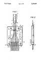
- FIG. 1is a front elevational fragmentary schematic view showing an embodiment of the invention.
- FIG. 2is a schematic side elevational view as seen from the right hand portion of FIG. 1.
- the devicein FIG. 1 in operative association with outside plant cable 11 having an outer shield 12 enclosing buffer tubes 13, 14, and 15 from which extend plural optical fibers 16.
- the shield 12is removed below a free end 18 immediately below a clamping area 19 engaged by a conventional clamp known in the art (not shown).
- the device 10comprises a two part housing which includes a base element 21 and a cover element 22 formed of clear synthetic resinous material, such as polycarbonate, in congruent relation therewith.
- the base element 21is approximately 3/8 inch thick, and is bounded by a first end edge 26, a second end edge 27, side edges 28 and 29, an outer surface 30, and an inner surface 31. Extending from the inner surface 31 is a recess 32 terminating in a first or entry end 33 and a second or exit end 34, and bounded by sides 35 and 36 as well as a lower planar surface 37.
- the second end 34is adapted to retain a plurality of flexible buffer tubes 39 which are clamped by the cover element 22 and which serve to guide the fibers 16 to a point of interconnection.
- the inner ends 40 thereofare positioned well within the recess, to enable the injection of a blocking sealant (not shown) of known type, after the fibers have been inserted therethrough.
- the cove element 22is formed of transparent synthetic resinous material and may be substantially thinner. It is bounded by first and second end edges 50 and 51, as well as side edges 52 and 53. A pair of upper bores 54 and 55 and lower bores. 56 and 57 extend through both the base and cover elements, to enable the elements to be maintained in abutted relation through the use of machine screws 58. A pair of centrally disposed bores 60 and 61 is also continuous through both elements, and enables the device 10 to be mounted on a stable surface (not shown).
- the exposed buffer tubes 13, 14, 15are removed, leaving an appropriate length of exposed fibers 16. These fibers are then passed through flexible plastic tubes 39. Both the buffer 13, 14, 15, and the flexible plastic tubes 39 may be temporarily secured using an adhesive such as cyanoacrylate. Next, a blocking sealant thereafter is injected into the free ends of the tubes 40, and the device closed by the placement of the cover element 22 and the engagement of the screws 58. The device 10 is thereafter anchored to a fixed surface using screws inserted through the bores 60 and 61.
- the fibers 16are open to continuous visual inspection, because of the transparency of the device, as is the general condition of all parts of the conductors disposed within the recess 32.
- the devicemay be fabricated at relatively low cost of manufacture using injection molding techniques, with a minimum of machining, and may be fabricated in a variety of sizes, depending upon the size of the cable to be accommodated.
Landscapes
- Physics & Mathematics (AREA)
- General Physics & Mathematics (AREA)
- Optics & Photonics (AREA)
- Light Guides In General And Applications Therefor (AREA)
- Installation Of Indoor Wiring (AREA)
Abstract
Description
Claims (3)
Priority Applications (2)
| Application Number | Priority Date | Filing Date | Title |
|---|---|---|---|
| US07/845,372US5239609A (en) | 1992-03-03 | 1992-03-03 | Means for routing buffer tube type fiber optical cable |
| PCT/US1993/001796WO1993018421A1 (en) | 1992-03-03 | 1993-03-01 | Means for routing buffer tube type fiber optical cable |
Applications Claiming Priority (1)
| Application Number | Priority Date | Filing Date | Title |
|---|---|---|---|
| US07/845,372US5239609A (en) | 1992-03-03 | 1992-03-03 | Means for routing buffer tube type fiber optical cable |
Publications (1)
| Publication Number | Publication Date |
|---|---|
| US5239609Atrue US5239609A (en) | 1993-08-24 |
Family
ID=25295088
Family Applications (1)
| Application Number | Title | Priority Date | Filing Date |
|---|---|---|---|
| US07/845,372Expired - LifetimeUS5239609A (en) | 1992-03-03 | 1992-03-03 | Means for routing buffer tube type fiber optical cable |
Country Status (2)
| Country | Link |
|---|---|
| US (1) | US5239609A (en) |
| WO (1) | WO1993018421A1 (en) |
Cited By (58)
| Publication number | Priority date | Publication date | Assignee | Title |
|---|---|---|---|---|
| US5335304A (en)* | 1993-04-30 | 1994-08-02 | The United States Of America As Represented By The Secretary Of The Army | Connector distribution assembly for a fiber optic detector system |
| GB2305258A (en)* | 1995-09-16 | 1997-04-02 | Bowthorpe Plc | Optic fibre splice enclosure with ducted tubes for fibres |
| US5636303A (en)* | 1995-12-18 | 1997-06-03 | World Precision Instruments, Inc. | Filterless chromatically variable light source |
| US5801328A (en)* | 1995-02-08 | 1998-09-01 | Dsc Communications Corporation | Cable EMI shield termination and enclosure |
| US6222976B1 (en)* | 1999-06-30 | 2001-04-24 | Lucent Technologies Inc. | Optical harness and cross-connect method |
| US6351590B1 (en)* | 1999-06-30 | 2002-02-26 | Lucent Technologies Inc. | Optical harness with optical connector and cross-connect method |
| US6442322B1 (en) | 2000-12-22 | 2002-08-27 | Jds Uniphase Corporation | Optical fiber management device |
| US6510273B2 (en)* | 2001-01-26 | 2003-01-21 | Molex Incorporated | Optical fiber management system |
| US20030031437A1 (en)* | 2001-08-10 | 2003-02-13 | 3M Innovative Properties Company | In-line shuffle modules utilizing three dimensional optical circuits |
| US20030031419A1 (en)* | 2001-08-10 | 2003-02-13 | 3M Innovative Properties Company | Optical manifold |
| WO2002065182A3 (en)* | 2001-02-15 | 2003-05-30 | Teraspan Networks Inc | Subsurface fibre optic cable network installation |
| US6594437B1 (en) | 2000-08-15 | 2003-07-15 | Fci Americas Technology, Inc. | Optical fiber separation and regrouping device |
| US6633717B1 (en)* | 2000-09-08 | 2003-10-14 | Telect, Inc. | High density fiber optic cable distribution frame system |
| US6650811B1 (en)* | 1998-06-23 | 2003-11-18 | Corning Cable Systems Llc | Protection of glass fibers for telecommunication with hollow leads |
| WO2003048830A3 (en)* | 2001-12-04 | 2003-12-04 | Molex Inc | Fanout system or apparatus for a fiber optic cable and including a method of fabricating same |
| US6668129B2 (en)* | 2001-01-24 | 2003-12-23 | Mitsubishi Cable Industries, Ltd. | Optical fiber wiring board having an extension portion |
| US7270485B1 (en) | 2006-06-23 | 2007-09-18 | Carlyle, Inc. | Device for furcating fiber optic cables |
| US20080279506A1 (en)* | 2004-12-22 | 2008-11-13 | John Kerry | Blown Optical Fibre Multi-Tube Terminal Connectors |
| US20090310928A1 (en)* | 2008-06-12 | 2009-12-17 | Wolf Kluwe | Universal cable bracket |
| US20100098386A1 (en)* | 2008-10-17 | 2010-04-22 | Kleeberger Terry M | Devices and associated methods for furcating fiber optic cables |
| US20100322581A1 (en)* | 2009-06-19 | 2010-12-23 | Cooke Terry L | High Fiber Optic Cable Packing Density Apparatus |
| US20100322583A1 (en)* | 2009-06-19 | 2010-12-23 | Cooke Terry L | High Density and Bandwidth Fiber Optic Apparatuses and Related Equipment and Methods |
| US20110150407A1 (en)* | 2009-12-18 | 2011-06-23 | Beamon Hubert B | Rotary Locking Apparatus for Fiber Optic Equipment Trays and Related Methods |
| WO2012018825A1 (en)* | 2010-08-02 | 2012-02-09 | Afl Telecommunications, Llc | Apparatus and method for preventing optical fiber and gel from ejecting out of buffer tubes in fiber optic cables |
| US8538226B2 (en) | 2009-05-21 | 2013-09-17 | Corning Cable Systems Llc | Fiber optic equipment guides and rails configured with stopping position(s), and related equipment and methods |
| US8542973B2 (en) | 2010-04-23 | 2013-09-24 | Ccs Technology, Inc. | Fiber optic distribution device |
| US8593828B2 (en) | 2010-02-04 | 2013-11-26 | Corning Cable Systems Llc | Communications equipment housings, assemblies, and related alignment features and methods |
| US8660397B2 (en) | 2010-04-30 | 2014-02-25 | Corning Cable Systems Llc | Multi-layer module |
| US8662760B2 (en) | 2010-10-29 | 2014-03-04 | Corning Cable Systems Llc | Fiber optic connector employing optical fiber guide member |
| US8699838B2 (en) | 2009-05-14 | 2014-04-15 | Ccs Technology, Inc. | Fiber optic furcation module |
| US8705926B2 (en) | 2010-04-30 | 2014-04-22 | Corning Optical Communications LLC | Fiber optic housings having a removable top, and related components and methods |
| US8712206B2 (en) | 2009-06-19 | 2014-04-29 | Corning Cable Systems Llc | High-density fiber optic modules and module housings and related equipment |
| US8718436B2 (en) | 2010-08-30 | 2014-05-06 | Corning Cable Systems Llc | Methods, apparatuses for providing secure fiber optic connections |
| US8879881B2 (en) | 2010-04-30 | 2014-11-04 | Corning Cable Systems Llc | Rotatable routing guide and assembly |
| US8913866B2 (en) | 2010-03-26 | 2014-12-16 | Corning Cable Systems Llc | Movable adapter panel |
| US8953924B2 (en) | 2011-09-02 | 2015-02-10 | Corning Cable Systems Llc | Removable strain relief brackets for securing fiber optic cables and/or optical fibers to fiber optic equipment, and related assemblies and methods |
| US8989547B2 (en) | 2011-06-30 | 2015-03-24 | Corning Cable Systems Llc | Fiber optic equipment assemblies employing non-U-width-sized housings and related methods |
| US8985862B2 (en) | 2013-02-28 | 2015-03-24 | Corning Cable Systems Llc | High-density multi-fiber adapter housings |
| US8995812B2 (en) | 2012-10-26 | 2015-03-31 | Ccs Technology, Inc. | Fiber optic management unit and fiber optic distribution device |
| US9008485B2 (en) | 2011-05-09 | 2015-04-14 | Corning Cable Systems Llc | Attachment mechanisms employed to attach a rear housing section to a fiber optic housing, and related assemblies and methods |
| US9022814B2 (en) | 2010-04-16 | 2015-05-05 | Ccs Technology, Inc. | Sealing and strain relief device for data cables |
| US9038832B2 (en) | 2011-11-30 | 2015-05-26 | Corning Cable Systems Llc | Adapter panel support assembly |
| US9059578B2 (en) | 2009-02-24 | 2015-06-16 | Ccs Technology, Inc. | Holding device for a cable or an assembly for use with a cable |
| US9075216B2 (en) | 2009-05-21 | 2015-07-07 | Corning Cable Systems Llc | Fiber optic housings configured to accommodate fiber optic modules/cassettes and fiber optic panels, and related components and methods |
| US9075217B2 (en) | 2010-04-30 | 2015-07-07 | Corning Cable Systems Llc | Apparatuses and related components and methods for expanding capacity of fiber optic housings |
| US9116324B2 (en) | 2010-10-29 | 2015-08-25 | Corning Cable Systems Llc | Stacked fiber optic modules and fiber optic equipment configured to support stacked fiber optic modules |
| US9213161B2 (en) | 2010-11-05 | 2015-12-15 | Corning Cable Systems Llc | Fiber body holder and strain relief device |
| US9250409B2 (en) | 2012-07-02 | 2016-02-02 | Corning Cable Systems Llc | Fiber-optic-module trays and drawers for fiber-optic equipment |
| US9279951B2 (en) | 2010-10-27 | 2016-03-08 | Corning Cable Systems Llc | Fiber optic module for limited space applications having a partially sealed module sub-assembly |
| US9519118B2 (en) | 2010-04-30 | 2016-12-13 | Corning Optical Communications LLC | Removable fiber management sections for fiber optic housings, and related components and methods |
| US9632270B2 (en) | 2010-04-30 | 2017-04-25 | Corning Optical Communications LLC | Fiber optic housings configured for tool-less assembly, and related components and methods |
| US9645317B2 (en) | 2011-02-02 | 2017-05-09 | Corning Optical Communications LLC | Optical backplane extension modules, and related assemblies suitable for establishing optical connections to information processing modules disposed in equipment racks |
| US9720195B2 (en) | 2010-04-30 | 2017-08-01 | Corning Optical Communications LLC | Apparatuses and related components and methods for attachment and release of fiber optic housings to and from an equipment rack |
| US10094996B2 (en) | 2008-08-29 | 2018-10-09 | Corning Optical Communications, Llc | Independently translatable modules and fiber optic equipment trays in fiber optic equipment |
| US10247889B1 (en)* | 2018-05-15 | 2019-04-02 | Te Connectivity Corporation | Overmolded breakout |
| US10330881B1 (en) | 2017-12-21 | 2019-06-25 | Afl Telecommunications Llc | Optical fiber furcation assemblies |
| US11294136B2 (en) | 2008-08-29 | 2022-04-05 | Corning Optical Communications LLC | High density and bandwidth fiber optic apparatuses and related equipment and methods |
| US11506852B2 (en)* | 2020-04-01 | 2022-11-22 | Afl Telecommunications Llc | Fiber pistoning solution |
Citations (3)
| Publication number | Priority date | Publication date | Assignee | Title |
|---|---|---|---|---|
| US4305642A (en)* | 1979-12-17 | 1981-12-15 | Western Electric Company, Inc. | Optical fiber transition device and assembly |
| US4744629A (en)* | 1985-08-16 | 1988-05-17 | Augat Inc. | Multifiber optical cable connector |
| US4884862A (en)* | 1988-10-17 | 1989-12-05 | Minnesota Mining And Manufacturing Company | Fiber optic fan-out module |
- 1992
- 1992-03-03USUS07/845,372patent/US5239609A/ennot_activeExpired - Lifetime
- 1993
- 1993-03-01WOPCT/US1993/001796patent/WO1993018421A1/enactiveApplication Filing
Patent Citations (3)
| Publication number | Priority date | Publication date | Assignee | Title |
|---|---|---|---|---|
| US4305642A (en)* | 1979-12-17 | 1981-12-15 | Western Electric Company, Inc. | Optical fiber transition device and assembly |
| US4744629A (en)* | 1985-08-16 | 1988-05-17 | Augat Inc. | Multifiber optical cable connector |
| US4884862A (en)* | 1988-10-17 | 1989-12-05 | Minnesota Mining And Manufacturing Company | Fiber optic fan-out module |
Non-Patent Citations (4)
| Title |
|---|
| A.T.T. Practice Instruction Sheet #633-501-101-141 Aug. 1984. |
| A.T.T. Practice Instruction Sheet 633 501 101 141 Aug. 1984.* |
| A.T.T. Practice Standard #631-299-110. Feb. 1988. |
| A.T.T. Practice Standard 631 299 110. Feb. 1988.* |
Cited By (98)
| Publication number | Priority date | Publication date | Assignee | Title |
|---|---|---|---|---|
| US5335304A (en)* | 1993-04-30 | 1994-08-02 | The United States Of America As Represented By The Secretary Of The Army | Connector distribution assembly for a fiber optic detector system |
| US5801328A (en)* | 1995-02-08 | 1998-09-01 | Dsc Communications Corporation | Cable EMI shield termination and enclosure |
| GB2305258A (en)* | 1995-09-16 | 1997-04-02 | Bowthorpe Plc | Optic fibre splice enclosure with ducted tubes for fibres |
| GB2305258B (en)* | 1995-09-16 | 1999-03-31 | Bowthorpe Plc | Optical fibre splice enclosures |
| US5636303A (en)* | 1995-12-18 | 1997-06-03 | World Precision Instruments, Inc. | Filterless chromatically variable light source |
| US6650811B1 (en)* | 1998-06-23 | 2003-11-18 | Corning Cable Systems Llc | Protection of glass fibers for telecommunication with hollow leads |
| US6222976B1 (en)* | 1999-06-30 | 2001-04-24 | Lucent Technologies Inc. | Optical harness and cross-connect method |
| US6351590B1 (en)* | 1999-06-30 | 2002-02-26 | Lucent Technologies Inc. | Optical harness with optical connector and cross-connect method |
| US6594437B1 (en) | 2000-08-15 | 2003-07-15 | Fci Americas Technology, Inc. | Optical fiber separation and regrouping device |
| US6633717B1 (en)* | 2000-09-08 | 2003-10-14 | Telect, Inc. | High density fiber optic cable distribution frame system |
| US6442322B1 (en) | 2000-12-22 | 2002-08-27 | Jds Uniphase Corporation | Optical fiber management device |
| US6668129B2 (en)* | 2001-01-24 | 2003-12-23 | Mitsubishi Cable Industries, Ltd. | Optical fiber wiring board having an extension portion |
| US6510273B2 (en)* | 2001-01-26 | 2003-01-21 | Molex Incorporated | Optical fiber management system |
| US6807355B2 (en) | 2001-02-15 | 2004-10-19 | Teraspan Networks, Inc. | Subsurface fibre optic cable network installation |
| AU2002234447C1 (en)* | 2001-02-15 | 2006-11-02 | Teraspan Networks Inc. | Subsurface fibre optic cable network installation |
| US20060204187A1 (en)* | 2001-02-15 | 2006-09-14 | Teraspan Networks, Inc. | Subsurface fibre optic cable network installation |
| US7050683B2 (en) | 2001-02-15 | 2006-05-23 | Teraspan Networks, Inc. | Subsurface fibre optic cable network installation |
| AU2002234447B2 (en)* | 2001-02-15 | 2005-12-08 | Teraspan Networks Inc. | Subsurface fibre optic cable network installation |
| US20050031287A1 (en)* | 2001-02-15 | 2005-02-10 | Teraspan Networks, Inc. | Subsurface fibre optic cable network installation |
| WO2002065182A3 (en)* | 2001-02-15 | 2003-05-30 | Teraspan Networks Inc | Subsurface fibre optic cable network installation |
| US6850684B2 (en) | 2001-08-10 | 2005-02-01 | 3M Innovative Properties Company | Three dimensional optical circuits |
| US7597483B2 (en) | 2001-08-10 | 2009-10-06 | 3M Innovative Properties Company | Optical manifold |
| US6847774B2 (en) | 2001-08-10 | 2005-01-25 | 3M Innovative Properties Company | Three dimensional optical circuits |
| US20030031437A1 (en)* | 2001-08-10 | 2003-02-13 | 3M Innovative Properties Company | In-line shuffle modules utilizing three dimensional optical circuits |
| US6832032B2 (en) | 2001-08-10 | 2004-12-14 | 3M Innovative Properties Company | In-line shuffle modules utilizing three dimensional optical circuits |
| US6655848B2 (en) | 2001-08-10 | 2003-12-02 | 3M Innovative Properties Company | Method of making an optical manifold |
| US20030031419A1 (en)* | 2001-08-10 | 2003-02-13 | 3M Innovative Properties Company | Optical manifold |
| US6549710B2 (en) | 2001-08-10 | 2003-04-15 | 3M Innovative Properties Company | Method of making a three dimensional optical circuit |
| US6556754B2 (en) | 2001-08-10 | 2003-04-29 | 3M Innovative Properties Company | Three dimensional optical circuit |
| WO2003048830A3 (en)* | 2001-12-04 | 2003-12-04 | Molex Inc | Fanout system or apparatus for a fiber optic cable and including a method of fabricating same |
| CN1294434C (en)* | 2001-12-04 | 2007-01-10 | 莫列斯公司 | Fan-out system or device for optical fiber cable, and manufacturing method thereof |
| US20080279506A1 (en)* | 2004-12-22 | 2008-11-13 | John Kerry | Blown Optical Fibre Multi-Tube Terminal Connectors |
| US7270485B1 (en) | 2006-06-23 | 2007-09-18 | Carlyle, Inc. | Device for furcating fiber optic cables |
| US20090310928A1 (en)* | 2008-06-12 | 2009-12-17 | Wolf Kluwe | Universal cable bracket |
| US7787740B2 (en) | 2008-06-12 | 2010-08-31 | Corning Cable Systems Llc | Universal cable bracket |
| US11086089B2 (en) | 2008-08-29 | 2021-08-10 | Corning Optical Communications LLC | High density and bandwidth fiber optic apparatuses and related equipment and methods |
| US10444456B2 (en) | 2008-08-29 | 2019-10-15 | Corning Optical Communications LLC | High density and bandwidth fiber optic apparatuses and related equipment and methods |
| US10094996B2 (en) | 2008-08-29 | 2018-10-09 | Corning Optical Communications, Llc | Independently translatable modules and fiber optic equipment trays in fiber optic equipment |
| US10120153B2 (en) | 2008-08-29 | 2018-11-06 | Corning Optical Communications, Llc | Independently translatable modules and fiber optic equipment trays in fiber optic equipment |
| US12072545B2 (en) | 2008-08-29 | 2024-08-27 | Corning Optical Communications LLC | High density and bandwidth fiber optic apparatuses and related equipment and methods |
| US10126514B2 (en) | 2008-08-29 | 2018-11-13 | Corning Optical Communications, Llc | Independently translatable modules and fiber optic equipment trays in fiber optic equipment |
| US10222570B2 (en) | 2008-08-29 | 2019-03-05 | Corning Optical Communications LLC | Independently translatable modules and fiber optic equipment trays in fiber optic equipment |
| US10416405B2 (en) | 2008-08-29 | 2019-09-17 | Corning Optical Communications LLC | Independently translatable modules and fiber optic equipment trays in fiber optic equipment |
| US10422971B2 (en) | 2008-08-29 | 2019-09-24 | Corning Optical Communicatinos LLC | High density and bandwidth fiber optic apparatuses and related equipment and methods |
| US9020320B2 (en) | 2008-08-29 | 2015-04-28 | Corning Cable Systems Llc | High density and bandwidth fiber optic apparatuses and related equipment and methods |
| US10459184B2 (en) | 2008-08-29 | 2019-10-29 | Corning Optical Communications LLC | High density and bandwidth fiber optic apparatuses and related equipment and methods |
| US11754796B2 (en) | 2008-08-29 | 2023-09-12 | Corning Optical Communications LLC | Independently translatable modules and fiber optic equipment trays in fiber optic equipment |
| US11609396B2 (en) | 2008-08-29 | 2023-03-21 | Corning Optical Communications LLC | High density and bandwidth fiber optic apparatuses and related equipment and methods |
| US10564378B2 (en) | 2008-08-29 | 2020-02-18 | Corning Optical Communications LLC | High density and bandwidth fiber optic apparatuses and related equipment and methods |
| US10606014B2 (en) | 2008-08-29 | 2020-03-31 | Corning Optical Communications LLC | Independently translatable modules and fiber optic equipment trays in fiber optic equipment |
| US10852499B2 (en) | 2008-08-29 | 2020-12-01 | Corning Optical Communications LLC | High density and bandwidth fiber optic apparatuses and related equipment and methods |
| US11294135B2 (en) | 2008-08-29 | 2022-04-05 | Corning Optical Communications LLC | High density and bandwidth fiber optic apparatuses and related equipment and methods |
| US11294136B2 (en) | 2008-08-29 | 2022-04-05 | Corning Optical Communications LLC | High density and bandwidth fiber optic apparatuses and related equipment and methods |
| US9910236B2 (en) | 2008-08-29 | 2018-03-06 | Corning Optical Communications LLC | High density and bandwidth fiber optic apparatuses and related equipment and methods |
| US11092767B2 (en) | 2008-08-29 | 2021-08-17 | Corning Optical Communications LLC | High density and bandwidth fiber optic apparatuses and related equipment and methods |
| US8172465B2 (en) | 2008-10-17 | 2012-05-08 | Netig Llc | Devices and associated methods for furcating fiber optic cables |
| US20100098386A1 (en)* | 2008-10-17 | 2010-04-22 | Kleeberger Terry M | Devices and associated methods for furcating fiber optic cables |
| US9059578B2 (en) | 2009-02-24 | 2015-06-16 | Ccs Technology, Inc. | Holding device for a cable or an assembly for use with a cable |
| US8699838B2 (en) | 2009-05-14 | 2014-04-15 | Ccs Technology, Inc. | Fiber optic furcation module |
| US8538226B2 (en) | 2009-05-21 | 2013-09-17 | Corning Cable Systems Llc | Fiber optic equipment guides and rails configured with stopping position(s), and related equipment and methods |
| US9075216B2 (en) | 2009-05-21 | 2015-07-07 | Corning Cable Systems Llc | Fiber optic housings configured to accommodate fiber optic modules/cassettes and fiber optic panels, and related components and methods |
| US20100322581A1 (en)* | 2009-06-19 | 2010-12-23 | Cooke Terry L | High Fiber Optic Cable Packing Density Apparatus |
| US8433171B2 (en) | 2009-06-19 | 2013-04-30 | Corning Cable Systems Llc | High fiber optic cable packing density apparatus |
| US8712206B2 (en) | 2009-06-19 | 2014-04-29 | Corning Cable Systems Llc | High-density fiber optic modules and module housings and related equipment |
| US20100322583A1 (en)* | 2009-06-19 | 2010-12-23 | Cooke Terry L | High Density and Bandwidth Fiber Optic Apparatuses and Related Equipment and Methods |
| US8625950B2 (en) | 2009-12-18 | 2014-01-07 | Corning Cable Systems Llc | Rotary locking apparatus for fiber optic equipment trays and related methods |
| US20110150407A1 (en)* | 2009-12-18 | 2011-06-23 | Beamon Hubert B | Rotary Locking Apparatus for Fiber Optic Equipment Trays and Related Methods |
| US8593828B2 (en) | 2010-02-04 | 2013-11-26 | Corning Cable Systems Llc | Communications equipment housings, assemblies, and related alignment features and methods |
| US8992099B2 (en) | 2010-02-04 | 2015-03-31 | Corning Cable Systems Llc | Optical interface cards, assemblies, and related methods, suited for installation and use in antenna system equipment |
| US8913866B2 (en) | 2010-03-26 | 2014-12-16 | Corning Cable Systems Llc | Movable adapter panel |
| US9022814B2 (en) | 2010-04-16 | 2015-05-05 | Ccs Technology, Inc. | Sealing and strain relief device for data cables |
| US8542973B2 (en) | 2010-04-23 | 2013-09-24 | Ccs Technology, Inc. | Fiber optic distribution device |
| US8705926B2 (en) | 2010-04-30 | 2014-04-22 | Corning Optical Communications LLC | Fiber optic housings having a removable top, and related components and methods |
| US9720195B2 (en) | 2010-04-30 | 2017-08-01 | Corning Optical Communications LLC | Apparatuses and related components and methods for attachment and release of fiber optic housings to and from an equipment rack |
| US9632270B2 (en) | 2010-04-30 | 2017-04-25 | Corning Optical Communications LLC | Fiber optic housings configured for tool-less assembly, and related components and methods |
| US9519118B2 (en) | 2010-04-30 | 2016-12-13 | Corning Optical Communications LLC | Removable fiber management sections for fiber optic housings, and related components and methods |
| US8660397B2 (en) | 2010-04-30 | 2014-02-25 | Corning Cable Systems Llc | Multi-layer module |
| US9075217B2 (en) | 2010-04-30 | 2015-07-07 | Corning Cable Systems Llc | Apparatuses and related components and methods for expanding capacity of fiber optic housings |
| US8879881B2 (en) | 2010-04-30 | 2014-11-04 | Corning Cable Systems Llc | Rotatable routing guide and assembly |
| US8913864B2 (en) | 2010-08-02 | 2014-12-16 | Afl Telecommunications Llc | Apparatus and method for preventing optical fiber and gel from ejecting out of buffer tubes in fiber optic cables |
| WO2012018825A1 (en)* | 2010-08-02 | 2012-02-09 | Afl Telecommunications, Llc | Apparatus and method for preventing optical fiber and gel from ejecting out of buffer tubes in fiber optic cables |
| US8718436B2 (en) | 2010-08-30 | 2014-05-06 | Corning Cable Systems Llc | Methods, apparatuses for providing secure fiber optic connections |
| US9279951B2 (en) | 2010-10-27 | 2016-03-08 | Corning Cable Systems Llc | Fiber optic module for limited space applications having a partially sealed module sub-assembly |
| US8662760B2 (en) | 2010-10-29 | 2014-03-04 | Corning Cable Systems Llc | Fiber optic connector employing optical fiber guide member |
| US9116324B2 (en) | 2010-10-29 | 2015-08-25 | Corning Cable Systems Llc | Stacked fiber optic modules and fiber optic equipment configured to support stacked fiber optic modules |
| US9213161B2 (en) | 2010-11-05 | 2015-12-15 | Corning Cable Systems Llc | Fiber body holder and strain relief device |
| US10481335B2 (en) | 2011-02-02 | 2019-11-19 | Corning Optical Communications, Llc | Dense shuttered fiber optic connectors and assemblies suitable for establishing optical connections for optical backplanes in equipment racks |
| US9645317B2 (en) | 2011-02-02 | 2017-05-09 | Corning Optical Communications LLC | Optical backplane extension modules, and related assemblies suitable for establishing optical connections to information processing modules disposed in equipment racks |
| US9008485B2 (en) | 2011-05-09 | 2015-04-14 | Corning Cable Systems Llc | Attachment mechanisms employed to attach a rear housing section to a fiber optic housing, and related assemblies and methods |
| US8989547B2 (en) | 2011-06-30 | 2015-03-24 | Corning Cable Systems Llc | Fiber optic equipment assemblies employing non-U-width-sized housings and related methods |
| US8953924B2 (en) | 2011-09-02 | 2015-02-10 | Corning Cable Systems Llc | Removable strain relief brackets for securing fiber optic cables and/or optical fibers to fiber optic equipment, and related assemblies and methods |
| US9038832B2 (en) | 2011-11-30 | 2015-05-26 | Corning Cable Systems Llc | Adapter panel support assembly |
| US9250409B2 (en) | 2012-07-02 | 2016-02-02 | Corning Cable Systems Llc | Fiber-optic-module trays and drawers for fiber-optic equipment |
| US8995812B2 (en) | 2012-10-26 | 2015-03-31 | Ccs Technology, Inc. | Fiber optic management unit and fiber optic distribution device |
| US8985862B2 (en) | 2013-02-28 | 2015-03-24 | Corning Cable Systems Llc | High-density multi-fiber adapter housings |
| US10330881B1 (en) | 2017-12-21 | 2019-06-25 | Afl Telecommunications Llc | Optical fiber furcation assemblies |
| US10247889B1 (en)* | 2018-05-15 | 2019-04-02 | Te Connectivity Corporation | Overmolded breakout |
| US11506852B2 (en)* | 2020-04-01 | 2022-11-22 | Afl Telecommunications Llc | Fiber pistoning solution |
Also Published As
| Publication number | Publication date |
|---|---|
| WO1993018421A1 (en) | 1993-09-16 |
Similar Documents
| Publication | Publication Date | Title |
|---|---|---|
| US5239609A (en) | Means for routing buffer tube type fiber optical cable | |
| US5450518A (en) | Optical fiber cable splice closure | |
| US5596670A (en) | Optical fiber cable enclosure | |
| US5235665A (en) | Branching device for fibre-optic cables | |
| CA2061911C (en) | Space-saving optical fiber cable closure | |
| US20200012064A1 (en) | Fiber optic module and system including rear connectors | |
| US6504987B1 (en) | Optical fiber organizer | |
| KR101118806B1 (en) | Telecommunications connection cabinet | |
| US4991928A (en) | Movable clamp for fiber optic enclosures | |
| US5185845A (en) | Optical fiber closure having enhanced storage capability | |
| US7400813B2 (en) | Fiber optic splitter module | |
| US12292612B2 (en) | Cable fixation devices and arrangements with improved installation and space utilization at telecommunications enclosures | |
| AU720876B2 (en) | Signal transmission media routing arrangement | |
| US5090792A (en) | Optical fiber tap handling tray | |
| EP0216073A1 (en) | Storing device for optical-fibre connectors | |
| KR100964278B1 (en) | Optical Splice Enclosure | |
| US5790739A (en) | Optical fiber interconnect and canister closure assembly | |
| US5222179A (en) | Means for routing ribbon type fiber optic cable | |
| JPH06503181A (en) | Connector device and method for optical fibers | |
| US11360264B2 (en) | Telecommunications splice arrangements | |
| US6751394B2 (en) | Sleeve insert and sleeve for guiding optical waveguide elements and for accommodating a splicing device | |
| GB2210472A (en) | Optical fibre package termination assembly | |
| EP1176446B1 (en) | Optic fibre separator | |
| JP3847042B2 (en) | Fiber optic cable clamping device | |
| WO2001096921A2 (en) | Fiber protection system and method including blocking kit |
Legal Events
| Date | Code | Title | Description |
|---|---|---|---|
| AS | Assignment | Owner name:PORTA SYSTEMS CORP., NEW YORK Free format text:ASSIGNMENT OF ASSIGNORS INTEREST.;ASSIGNOR:AUTERI, ROBERT P.;REEL/FRAME:006049/0050 Effective date:19920219 | |
| STCF | Information on status: patent grant | Free format text:PATENTED CASE | |
| AS | Assignment | Owner name:AUGAT INC., MASSACHUSETTS Free format text:ASSIGNMENT OF ASSIGNORS INTEREST;ASSIGNOR:PORTA SYSTEMS CORP.;REEL/FRAME:007869/0301 Effective date:19960313 | |
| FEPP | Fee payment procedure | Free format text:PAYOR NUMBER ASSIGNED (ORIGINAL EVENT CODE: ASPN); ENTITY STATUS OF PATENT OWNER: LARGE ENTITY | |
| FPAY | Fee payment | Year of fee payment:4 | |
| AS | Assignment | Owner name:THOMAS & BETTS INTERNATIONAL, INC., NEVADA Free format text:ASSIGNMENT OF ASSIGNORS INTEREST;ASSIGNOR:AUGAT INC.;REEL/FRAME:009342/0330 Effective date:19980630 | |
| FPAY | Fee payment | Year of fee payment:8 | |
| AS | Assignment | Owner name:ALCOA FUJIKURA LIMITED, TENNESSEE Free format text:ASSIGNMENT OF ASSIGNORS INTEREST;ASSIGNOR:THOMAS & BETTS INTERNATIONAL, INC.;REEL/FRAME:012002/0927 Effective date:20010618 | |
| FPAY | Fee payment | Year of fee payment:12 | |
| AS | Assignment | Owner name:AFL TELECOMMUNICATIONS LLC, TENNESSEE Free format text:ASSIGNMENT OF ASSIGNORS INTEREST;ASSIGNOR:ALCOA FUJIKURA LIMITED;REEL/FRAME:017198/0463 Effective date:20051110 Owner name:AFL TELECOMMUNICATIONS LLC, TENNESSEE Free format text:ASSIGNMENT OF ASSIGNORS INTEREST;ASSIGNOR:ALCOA FUJIKURA LIMITED;REEL/FRAME:017045/0733 Effective date:20051110 |