US5239575A - Telephone dial-inbound data acquisition system with demand reading capability - Google Patents
Telephone dial-inbound data acquisition system with demand reading capabilityDownload PDFInfo
- Publication number
- US5239575A US5239575AUS07/727,171US72717191AUS5239575AUS 5239575 AUS5239575 AUS 5239575AUS 72717191 AUS72717191 AUS 72717191AUS 5239575 AUS5239575 AUS 5239575A
- Authority
- US
- United States
- Prior art keywords
- host computer
- data unit
- remote data
- rdu
- time
- Prior art date
- Legal status (The legal status is an assumption and is not a legal conclusion. Google has not performed a legal analysis and makes no representation as to the accuracy of the status listed.)
- Expired - Fee Related
Links
- 238000012546transferMethods0.000claimsabstractdescription8
- 238000004891communicationMethods0.000claimsdescription35
- 238000000034methodMethods0.000claimsdescription22
- 238000012544monitoring processMethods0.000claimsdescription7
- XLYOFNOQVPJJNP-UHFFFAOYSA-NwaterSubstancesOXLYOFNOQVPJJNP-UHFFFAOYSA-N0.000claimsdescription7
- 238000001514detection methodMethods0.000abstractdescription16
- 230000000737periodic effectEffects0.000abstractdescription6
- 238000012360testing methodMethods0.000description13
- 230000008901benefitEffects0.000description9
- 238000005259measurementMethods0.000description7
- 230000008569processEffects0.000description6
- 230000008878couplingEffects0.000description4
- 238000010168coupling processMethods0.000description4
- 238000005859coupling reactionMethods0.000description4
- 230000006870functionEffects0.000description4
- 230000002452interceptive effectEffects0.000description4
- 238000010586diagramMethods0.000description3
- 230000005611electricityEffects0.000description3
- 230000033001locomotionEffects0.000description3
- 238000009877renderingMethods0.000description3
- 238000005070samplingMethods0.000description3
- 230000001629suppressionEffects0.000description3
- 230000001052transient effectEffects0.000description3
- WHXSMMKQMYFTQS-UHFFFAOYSA-NLithiumChemical compound[Li]WHXSMMKQMYFTQS-UHFFFAOYSA-N0.000description2
- 230000009471actionEffects0.000description2
- 230000005540biological transmissionEffects0.000description2
- 238000006243chemical reactionMethods0.000description2
- 230000000977initiatory effectEffects0.000description2
- 238000009434installationMethods0.000description2
- 229910052744lithiumInorganic materials0.000description2
- 230000001105regulatory effectEffects0.000description2
- 230000004044responseEffects0.000description2
- 230000003213activating effectEffects0.000description1
- 238000007792additionMethods0.000description1
- 230000003321amplificationEffects0.000description1
- 238000013459approachMethods0.000description1
- 230000009286beneficial effectEffects0.000description1
- 230000000903blocking effectEffects0.000description1
- 238000004364calculation methodMethods0.000description1
- 230000008859changeEffects0.000description1
- 230000003750conditioning effectEffects0.000description1
- 238000010276constructionMethods0.000description1
- 239000013078crystalSubstances0.000description1
- 238000005520cutting processMethods0.000description1
- 230000001351cycling effectEffects0.000description1
- 230000001934delayEffects0.000description1
- 230000001419dependent effectEffects0.000description1
- 238000009826distributionMethods0.000description1
- 230000000694effectsEffects0.000description1
- 230000002708enhancing effectEffects0.000description1
- 230000003628erosive effectEffects0.000description1
- JEIPFZHSYJVQDO-UHFFFAOYSA-Nferric oxideChemical compoundO=[Fe]O[Fe]=OJEIPFZHSYJVQDO-UHFFFAOYSA-N0.000description1
- 238000004519manufacturing processMethods0.000description1
- QSHDDOUJBYECFT-UHFFFAOYSA-NmercuryChemical compound[Hg]QSHDDOUJBYECFT-UHFFFAOYSA-N0.000description1
- 229910052753mercuryInorganic materials0.000description1
- 238000012986modificationMethods0.000description1
- 230000004048modificationEffects0.000description1
- 238000003199nucleic acid amplification methodMethods0.000description1
- 239000013307optical fiberSubstances0.000description1
- 238000003860storageMethods0.000description1
- 238000012956testing procedureMethods0.000description1
- 230000002618waking effectEffects0.000description1
Images


Classifications
- G—PHYSICS
- G01—MEASURING; TESTING
- G01D—MEASURING NOT SPECIALLY ADAPTED FOR A SPECIFIC VARIABLE; ARRANGEMENTS FOR MEASURING TWO OR MORE VARIABLES NOT COVERED IN A SINGLE OTHER SUBCLASS; TARIFF METERING APPARATUS; MEASURING OR TESTING NOT OTHERWISE PROVIDED FOR
- G01D4/00—Tariff metering apparatus
- G01D4/002—Remote reading of utility meters
- G01D4/004—Remote reading of utility meters to a fixed location
- H—ELECTRICITY
- H04—ELECTRIC COMMUNICATION TECHNIQUE
- H04M—TELEPHONIC COMMUNICATION
- H04M11/00—Telephonic communication systems specially adapted for combination with other electrical systems
- H04M11/002—Telephonic communication systems specially adapted for combination with other electrical systems with telemetering systems
- Y—GENERAL TAGGING OF NEW TECHNOLOGICAL DEVELOPMENTS; GENERAL TAGGING OF CROSS-SECTIONAL TECHNOLOGIES SPANNING OVER SEVERAL SECTIONS OF THE IPC; TECHNICAL SUBJECTS COVERED BY FORMER USPC CROSS-REFERENCE ART COLLECTIONS [XRACs] AND DIGESTS
- Y02—TECHNOLOGIES OR APPLICATIONS FOR MITIGATION OR ADAPTATION AGAINST CLIMATE CHANGE
- Y02B—CLIMATE CHANGE MITIGATION TECHNOLOGIES RELATED TO BUILDINGS, e.g. HOUSING, HOUSE APPLIANCES OR RELATED END-USER APPLICATIONS
- Y02B90/00—Enabling technologies or technologies with a potential or indirect contribution to GHG emissions mitigation
- Y02B90/20—Smart grids as enabling technology in buildings sector
- Y—GENERAL TAGGING OF NEW TECHNOLOGICAL DEVELOPMENTS; GENERAL TAGGING OF CROSS-SECTIONAL TECHNOLOGIES SPANNING OVER SEVERAL SECTIONS OF THE IPC; TECHNICAL SUBJECTS COVERED BY FORMER USPC CROSS-REFERENCE ART COLLECTIONS [XRACs] AND DIGESTS
- Y04—INFORMATION OR COMMUNICATION TECHNOLOGIES HAVING AN IMPACT ON OTHER TECHNOLOGY AREAS
- Y04S—SYSTEMS INTEGRATING TECHNOLOGIES RELATED TO POWER NETWORK OPERATION, COMMUNICATION OR INFORMATION TECHNOLOGIES FOR IMPROVING THE ELECTRICAL POWER GENERATION, TRANSMISSION, DISTRIBUTION, MANAGEMENT OR USAGE, i.e. SMART GRIDS
- Y04S20/00—Management or operation of end-user stationary applications or the last stages of power distribution; Controlling, monitoring or operating thereof
- Y04S20/30—Smart metering, e.g. specially adapted for remote reading
Definitions
- the inventionrelates to the field of remote data acquisition and, more particularly, to a system for periodically communicating data acquired by a remote data unit over a dial-up telephone line to a central computer and having demand reading capability.
- a remote data unitalso known as a meter interface unit (MIU)
- MIUmeter interface unit
- This type of systemenables the utility to automatically and remotely read a customer's utility meter without having to send a person to the customer's location to physically read the meter.
- Prior art automatic meter reading systemshave generally used one of three forms of communication media. These are radio (RF), two-way interactive cable television (CATV), or dial-up telephone lines.
- RFradio
- CATVtwo-way interactive cable television
- dial-up telephone linesdial-up telephone lines
- the second type of systemwhich uses two-way interactive coaxial cable
- a remote data unit located at a customer's siteperiodically acquires utility meter consumption data and transmits it back to a central computer over a cable television coaxial cable.
- One drawback to this systemis that it can only operate with a two-way interactive cable system since signal amplification is required from the customer's location back to the cable head-end.
- two-way cable systemsare relatively uncommon and therefore their use in automatic meter reading systems is limited.
- Telephone-based automatic meter reading (AMR) systemsgenerally fall into two categories: so-called telephone "dial-outbound” systems and telephone "dial-inbound” systems.
- a telephone dial-outbound systemis exemplified by U.S. Pat. No. 4,582,152.
- communicationis established from a central (host) computer to a remote data unit located at the customer's site and connected to utility meters.
- Access to the RDUis made through a special subscriber test trunk which enables the host computer to be connected to a particular RDU without ringing a customer's telephone.
- This systemhas the advantage that the host computer can dial and access any RDU in the system at any time. This enables a utility to make a meter reading at-will, for example, when a customer has his service disconnected for the purposes of rendering a final bill.
- this systemhas the drawback of requiring special test trunk access circuitry which has to be installed at each telephone exchange within a utility's service area.
- This special circuitryenables the host computer to communicate with the RDUs connected through the particular exchange without putting a ringing signal on the customer's line.
- Another disadvantageis that this particular arrangement requires the cooperation of the local telephone company to purchase and install the special circuitry at each exchange.
- a pseudorandom number generatoris provided at the RDU which is used to randomly select a callback time for the RDU.
- the RDU"wakes-up", dials the host computer's telephone number via a modem provided in the RDU and, upon making the connection with the host computer, transmits meter reading data back to the host. Randomization of the callback times is required since there can be several thousands of RDUs in a system.
- the callback timescan be spread out over the thirty day period, thus minimizing collisions in callback times. If a collision does occur, the RDU is programmed to pause for several seconds and retry the connection. If no connection is made after a predetermined number of retries, the RDU is reset.
- an RDUis programmed to call the host computer at a precise real time, as indicated by an onboard real-time clock in the RDU.
- the RDUseizes the telephone line and transmits meter reading data to the host computer.
- the host computerthen sends a signal containing the desired next real time of callback to the RDU where it is stored.
- the host computeralso sends a synchronization signal to force the real time clock at the RDU to synchronize with a master clock associated with the host computer.
- U.S. Pat. No. 4,056,684shows a telephone dial-inbound system for remote alarm monitoring.
- Alarm monitoring circuitry at a customer's homeperiodically dials into a host computer to indicate proper operation of the system.
- the host computerdownloads a desired time interval to the remote alarm monitoring unit.
- the remote alarm monitoring unitwhich has a clock, then waits the appropriate amount of time, as indicated by the time interval data sent from the host unit, until it calls back again.
- RDUnot interferes with the normal operation of a customer's telephone. Not only can such interference be annoying to a customer, who may find he cannot use his telephone when the RDU is attempting to access the host computer, but it can be potentially life threatening if the customer needs to use the phone to dial the police or fire department in an emergency. Therefore, many telephone companies require any sort of auxiliary device which is connected in parallel with the customer's telephone not interfere in any way with the normal operation of the telephone.
- the RDUmust be fail-safe in this regard--the RDU must not under any circumstance accidentally seize the line while a customer is using his phone, and must immediately release the line if the customer picks up the telephone handset to make a call.
- U.S. Pat. No. 4,578,534describes a telephone dial-inbound data acquisition system in which an RDU detects and intercepts a single ringing signal and causes the RDU to call back the host computer if such a single ring is detected. If more than one ring is detected, the RDU shuts down and allows normal operation of the customer's telephone.
- U.S. Pat. No. 4,847,892describes a telephone based data acquisition system in which an RDU has a real time clock and calls a host computer on a periodic basis, e.g. once a month.
- the RDUis placed in a "standby" mode for a call from the host computer.
- the RDUif a single ringing signal is detected the RDU immediately calls back the host computer to transmit its current data.
- scheduled periodic data transferstake place without any action of a utility or the requirement that the host computer call up the RDU to take the reading.
- the RDUis capable of being accessed on a daily basis during the predetermined "window" during which the RDU is in its "standby” mode. This enables the utility to take a daily reading of a utility meter.
- telephone-dial-inbound automatic meter reading RDUsSince telephone-dial-inbound automatic meter reading RDUs must be capable of operation during periods in which telephone line power may fail or not be available, they normally require some sort of onboard battery for backup power. While the use of some types of batteries, such as lithium batteries, in combination with low power consumption integrated circuit devices, have extended the time period over which an RDU may operate without needing a battery change, it is a very desirable feature that a utility be alerted when the battery power for a particular RDU begins to fall below a critical threshold. In addition, utilities have indicated the desire to know if the RDU or its associated utility meter is being tampered with. In either of the foregoing cases, low battery voltage or tampering indication, it would be desirable that the RDU immediately dial the host computer and identify the problem and its nature.
- batteriessuch as lithium batteries
- the present inventionovercomes the various drawbacks of prior art telephone dial-inbound data acquisition systems while providing many desirable features.
- the inventionconcerns an apparatus for transferring data over a telephone network comprising a remote data unit (RDU) and a host computer, with the remote data unit and host computer being interconnected over a dial-up telephone network.
- the remote data unitincludes means for storing a desired callback start time and a real time clock for generating an indication of real time.
- the remote data unitalso includes means for generating an offset time interval in a pseudorandom manner and means for adding the offset time interval to the desired callback start time to generate an actual callback time. This actual callback time is then continuously compared with the real time generated by the real time clock in the RDU.
- the call placement processis then begun by the remote data unit when the real time equals the actual callback time.
- the remote data unitthen transfers data from the remote unit to the host computer. Subsequently, the host computer transfers a new callback start time to the remote data unit. Communications between the remote data unit and the host computer are then terminated.
- the remote data unitwill call back during a predetermined "window" of time.
- the start of this time windowis the callback start time transmitted from the host computer to the remote data unit during a prior communications session.
- the offset time intervalwhich is generated in a pseudorandom manner at the remote data unit, is then added to the callback start time.
- the resultant actual callback time(the callback start time plus the offset time interval) is then used as the next time of callback to the host computer.
- several remote data unitscan be assigned identical callback start times, while the offset time intervals randomly generated at each remote data unit will cause the actual callback times to differ slightly during a predetermined window of time.
- Thisenables multiple RDUs to call a host computer during a relatively short (on the order of one and one-half minutes) "window" of time, while minimizing the chances of collisions between each call.
- the number of RDUs sharing a timeslot and the pseudorandomization algorithmcan be selected to optimize channel loading. This dramatically raises the throughput of the system over prior art systems where each RDU calls back during a fixed or limited range of times.
- Throughput of the present inventionmay be further improved by having the remote data unit calculate the next actual callback time while it is still in communication with the host computer and transferring this actual callback time indication to the host computer.
- the host computermay then compare this actual callback time with callback times of other remote data units within the system. If the host computer detects a conflict or uneven distribution of actual callback times, it can then signal the particular RDU, while it is still in communication with the host computer, to generate another offset time interval and calculate a new actual callback time until an acceptable actual callback time is indicated by the remote data unit.
- the offset time intervalis generated in a pseudorandom fashion by utilizing the "hundredths of a second counter" of the real time clock provided at the remote data unit.
- the count value of the hundredths of a second counter of the real time clockis sampled. Since the actual time that the remote data unit accesses a line will vary slightly, due to the amount of time it takes to dial up the host computer through the telephone network, the hundredths of a second digits, which are free running in the real time clock, will result in a random number between "00" and "99".
- the hundredths of a second count value of every RDU in the systemwill be random with respect to every other RDU. This number is then used as the number of seconds for the offset time interval for the next scheduled callback time.
- the host computermay download the next desired callback start time, to which the offset time interval is added, or the remote data unit may be programmed to use the same callback start time for the next reporting period as used previously. This approach maximizes the efficiency of the RDU program design by avoiding complex and lengthy mathematical randomization formulas.
- the remote data unitmay include means for mathematically computing a pseudorandom reporting time and means for comparing this pseudorandom time with a real time clock at the remote data unit.
- the remote data unitseizes the telephone lines, dials the host computer, and transfers data from the remote unit to the host computer. While still in communication with the host computer, the remote data unit then calculates a new pseudorandom time signal and transmits it to the host computer.
- the host computercontains a table of allowable callback times and compares this pseudorandomly generated time signal, which is indicative of the next desired callback time for the remote data unit, with all allowable callback times for all remote data units in the system.
- the host computeracknowledges this and the remote data unit then uses this time as its callback time on the next call. If this time is not acceptable, the host computer so indicates and causes the remote data unit to recompute a new callback time, and then checks the availability with the host computer to see if the time is acceptable.
- the host computermay also send an indication to the remote data unit of a range of allowable times so as to constrain the generation of the pseudorandomly generated time signal to the allowable range.
- circuitryfor detecting an alarm condition at the remote data unit and, in response to such alarm condition, immediately accessing the telephone line and transferring a signal indicative of this alarm condition to the host computer.
- This alarm conditionmay be an indication of voltage of a battery powering the remote data unit dropping below a predetermined limit.
- the battery conditioncan be checked and reported to the host computer during a regularly scheduled communications session.
- the alarm conditioncan also be an indication of tampering with the remote data unit or a utility meter associated with the remote data unit.
- tamperingis detected by applying a periodic pulsed current to a conductive loop and detecting the continuity of this loop.
- Pulsing the current on the loophas the advantages of conserving battery power at the remote data unit and being more noise immune. This is because a higher pulse of current may be applied to the conductive loop for a short period of time for the same size battery than would be practical if a continuous signal were applied to the loop, and because any noise induced in the loop is ignored except during the sampling period in which the pulse is applied.
- the inventionfurther includes circuitry for detecting whether the telephone line is in an on-hook or off-hook condition.
- This circuitryincludes means for detecting the electrical characteristics associated with on-hook and off-hook conditions for a particular remote data unit and other devices and telephones connected to a customer's telephone line.
- the off-hook condition detecting circuitrycan include means for detecting the tip-to-ring voltage on the telephone line and disconnecting the remote data unit from the telephone line when this voltage drops below a predetermined value.
- the off-hook condition detecting meansalso contains circuitry for blocking access to the telephone line by the remote data unit if the tip-to-ring voltage falls below a predetermined value. In this fashion, the remote data unit is prevented from seizing the telephone line if an off-hook condition is detected, e.g.
- the RDUwill also immediately disconnect from the host computer if it detects that the customer has taken the phone off-hook. Both of these features are important because a remote data unit must not interfere with the normal operation of a customer's telephone and must make the telephone immediately available in the case of emergencies.
- Prior art on-hook/off-hook detection circuitsgenerally only to look to see whether the voltage on the telephone line has fallen below a certain fixed threshold value, where this threshold value is considered to indicate an off-hook condition.
- this threshold valueis considered to indicate an off-hook condition.
- analog to digital conversion circuitryin conjunction with a microcomputer dedicated to monitor line characteristics, the present invention provides the capability to adapt the RDU to numerous telephone line environments.
- the present inventionprovides a more accurate and reliable off-hook condition detecting scheme by establishing and storing an initial baseline of actual on-hook and off-hook voltages for a particular telephone line to which the RDU is connected and then monitoring the line voltage for changes which result in the ratio of the baseline on-hook or off-hook voltage to the respective monitored on-hook or off-hood voltage falling below a predetermined value.
- This systemnot only prevents accidental seizure or failure to release in the presence of an off-hook condition, but also prevents the RDU from being locked out from access to the telephone line if the telephone line voltage drops below a predetermined value, even through this predetermined value does not actually indicate an off-hook condition.
- This methodalso allows the RDU to "learn" its respective telephone line characteristics and adapt its operating limits accordingly, thereby greatly enhancing its capability of operating under varying telephone line conditions.
- the RDUcould falsely believe that the customer's telephone was off-hook even though it was actually not, due to the supply voltage fluctuating below the preset level.
- the present inventionalso improves upon prior art methods by providing the capability of detecting an off-hook condition during pulse dialing.
- the remote data unitincludes circuitry for detecting a predetermined number of normal ringing signals applied to the telephone network. In response to the detection of such predetermined number of ringing signals, the remote data unit accesses the telephone network and establishes communication between the host computer and remote data unit. This arrangement enables a utility to dial-up the remote data unit on demand to take a meter reading at any time.
- the ring signal detection circuitrymay be programmed to respond to one or more normal rings which would be heard by a customer. Preferably the number of rings is one. If more rings than the predetermined number are detected, the RDU assumes it is a regular telephone call and takes no further action.
- the RDUthen immediately calls back the host computer to transmit its data. This allows polling of the remote data unit at any time by a utility.
- the first ringis not intercepted as in the case of some prior art units, but is allowed to ring a customer's telephone. If a customer does not pick up the telephone, then the RDU will initiate its callback as described above. If the customer picks up his telephone, assuming that it is a call for him, a utility company operator would instruct the customer to allow his phone to ring one time unanswered, so the meter can be read automatically.
- the first ringis not intercepted, absorbed or in any way eliminated since some telephone companies do not find this practice to be acceptable. Furthermore, some types of single ring detection circuits which intercept the first ring could potentially fail in an off-hook condition, thereby rendering a customer's telephone inoperative.
- An additional feature of the present inventionis the provision of an expansion bus at the remote data unit.
- the expansion busaccepts auxiliary circuit cards for direct communication with the remote data unit.
- auxiliary circuit cardscould implement additional desirable features, such as additional memory for the RDU, demand recording capabilities, time of use billing capability, energy management controls, pulse accumulator, radio frequency data link, or the like.
- the circuitry of the present inventionis designed using low power integrated circuitry to minimize battery drain and thereby prolong the period of time between battery replacement. Furthermore, it is contemplated that the circuitry of the remote data unit may be placed in a separate enclosure remote from the utility meter. Alternatively, the circuitry for the remote data unit may be integrated into the mechanical components of a meter register (e.g. a water, gas, or electric meter).
- a meter registere.g. a water, gas, or electric meter.
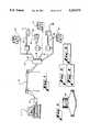
- FIG. 1illustrates the overall arrangement of a remote data acquisition system utilizing the principles of the present invention
- FIG. 2shows a utility meter incorporating an onboard remote data acquisition unit
- FIGS. 6A, 6B, 7A, 7B, 8A-8Care detailed schematic diagrams of the blocks shown in FIGS. 4, and 5, respectively.
- FIG. 9illustrates a low battery warning circuit which can be incorporated into the power supply shown in FIG. 7;
- FIG. 10shows the arrangement of expansion bus ports for the remote data unit shown in FIGS. 3-8.
- FIG. 1shows an overall arrangement of the remote data acquisition system of the present invention.
- a host computerwhich may be an IBM PC or compatible or other type of computer, is connected to dial-up telephone line 3 via a telephone modem 4.
- Telephone line 3is connected to a local telephone exchange 5.
- Telephone exchange 5is connected to other similar exchanges in a well known fashion.
- Each telephone exchange 5is connected to a customer site via local line 6.
- a remote data unit (RDU) 7whose construction and operation will be described in more detail below.
- Each RDU 7is connected via a communications channel 9 with a utility meter, such as a water meter 11, electric meter 13 or gas meter 15.
- Communications channel 9may comprise wires, coaxial cable, optical fiber, a radio frequency link, or the like.
- Communications channel 9enables communication between the register associated with a utility meter 11, 13, or 15 and its associated RDU 7, so that the amount of water ,electricity, or gas indicated by these meter registers may be communicated to its associated RDU 7.
- each RDU 7is capable of reading up to eight different meters or sources of data signals at a time.
- Each RDU 7is connected in parallel to local telephone line 6. Associated with each line 6 is a customer's telephone or other type of telephone data set 17.
- the utility meter registers associated with meters 11, 13, or 15are of the "absolute-encoder" type; i.e. encoder wheels associated with the meter register display encode the reading of the display so that when circuitry associated with the meter display is interrogated, the encoded register reading corresponds with the amount visually shown on the register display.
- encoder wheels associated with the meter register displayencode the reading of the display so that when circuitry associated with the meter display is interrogated, the encoded register reading corresponds with the amount visually shown on the register display.
- Such an encoded register and associated circuitryis shown in U.S. Pat. No. 4,085,287.
- a meter registermay count pulses generated by the motion of the measuring element of its associated meter 11, 13, or 15. These pulses may be accumulated in a memory device associated with the meter register or accumulated by its associated RDU, as described in more detail below.
- each RDU 7contains circuitry for automatically and periodically dialing up host computer 1 via telephone line 3 and 6 for communicating this consumption data back to host computer 1.
- Each RDU 7further includes circuitry which is responsive to a ringing signal initiated by host computer 1 to cause RDU 7 to immediately call back host computer 1 at times other than its periodic automatic callback time. This enables a utility to take a reading of utility meters 11, 13, or 15 on demand.
- FIG. 2illustrates an alternative embodiment wherein the circuitry associated with each RDU 7 is integrated within the same enclosure 19 containing the utility meter register associated with utility meters 11, 13, or 15.
- This integrated RDU/register 19has the benefit of eliminating an additional enclosure which would otherwise be required for an RDU 7 shown in FIG. 1. It also eliminates the need for a separate communications channel 9 between an RDU and its associated utility meter and minimizes unit cost.
- RDU 7(or the integrated version 19 as shown in FIG. 2) is shown in block diagram form in FIGS. 3, 4, and 5.
- FIGS. 6A, 6B, 7A, 7B, 8A-8Care detailed schematics of the correspondingly numbered blocks shown in FIGS. 3, 4, and 5.
- Block 21is the telephone line transient suppression circuit. Circuit 21 is connected to local telephone line 6 and serves the purpose of rectifying the telephone line voltage to allow either polarity of the tip-to-ring connection to function identically. Connected to transient suppression circuit 21 is hook-switch circuitry 23 which is activated by "back end" microprocessor 51. Hook-switch circuitry 23 is activated whenever microprocessor 51 determines that it is time to initiate a callback to host computer 1. Such a call only occurs after telephone line 6 is tested to see whether it is available (that is, if an on-hook condition is detected). Line testing occurs when microprocessor 51 activates hook-switch circuit 23. This initiates the powering up of the circuitry shown in FIGS. 3 and 6A, 6B to test the line and determine that it is available (on-hook).
- microprocessor 51proceeds normally to place a telephone call to host computer 1. However, if telephone line 6 is determined to be in an off-hook condition, microprocessor 51 takes certain steps to prevent RDU 7 from initiating such a call.
- microprocessor 51controls the status of hook-switch circuitry 23 by clocking data into local telephone line microcontroller 31. Data is clocked into microcontroller 31 indicating what the tip-to-ring voltage on the telephone line should be. Local microcontroller 31 is powered up through power supply 27. The tip-to-ring voltage is sensed through line sense circuit 29. The output of line sense circuit 29 is applied to an A-to-D converter incorporated as part of microcontroller 31. The A-to-D converter generates a digital representation of the tip-to-ring voltage and compares to a programmable reference level representative of an off-hook condition. The reference level can be a ratio of the previous result of measuring the tip-to-ring voltage during installation, or it can be remotely programmed by the host computer.
- RDU 7Prior to seizing the line, RDU 7 compares an average of the current line voltage to this reference level, and if greater or equal to, the line is assumed to be “on-hook” and available for use by RDU 7. If this voltage is less than the reference level, the line is assumed to be "off-hook” and therefore, unavailable for use at that time.
- Microcontroller 31then activates a second hook-switch circuit 35.
- Hook-switch 23 and second hook-switch 35provide redundant protection from RDU 7 going off-hook accidentally. This arrangement prevents either microcontroller 31 or back-end microprocessor 51 from independently causing RDU 7 to seize telephone line 6 and go into an off-hook condition. Both microcontroller 31 and microprocessor 51 must be activated at the same time and activate their respective hook-switches 35 and 23 before telephone line 6 can be seized.
- Watchdog timer 47also prevents RDU 7 from remaining in an off-hook condition for more than a predetermined amount of time, e.g. four minutes. If watchdog timer 47 has not been reset by microprocessor 51 within this predetermined time period, power supply 41 is turned off causing RDU 7 to shut down. This prevents RDU 7 from accidentally locking up and seizing telephone line 6 in the event of a component failure or error.
- a predetermined amount of timee.g. four minutes.
- Modem signal coupling transformer 37couples signals from modem 57 to the telephone lines 6 via hook-switch 23 and transient suppression circuit 21.
- Data signalsare applied from microprocessor 51 to modem 57 in a well known fashion. These data signals may be, for example, data indicative of a utility meter reading, an alarm condition, a low battery indication, tampering indication, or the like.
- microcontroller 31continuously monitors the telephone line voltage via line sense circuitry 29 in order to determine whether a telephone or other data set device 17, which is connected in parallel to telephone line 6, has gone off-hook.
- Most telephone companiesrequire that any auxiliary device connected to the telephone line, such as RDU 7, automatically and immediately disconnect from the telephone line in the event a customer wishes to use the telephone or other telephone data set. Ideally, this should be done quickly and without any interference to the customer's normal use of his telephone. This also represents a safety feature in the event the customer needs to use his telephone in an emergency, e.g. to telephone the police or fire department.
- Line sense circuitry 29in combination with the circuitry of microcontroller 31 accomplishes this by continuously monitoring the voltage of telephone line 6 and calculating an average of the voltage on the line to determine when any changes have occurred which would indicate another device connected to lines 6 going off-hook. More particularly, after RDU 7 has seized the line, it again measures the tip-to-ring voltage. This measurement is then used as a basis for determining subsequent customer off-hook conditions. The MIU continually samples and measures the tip-to-ring voltage and if this voltage falls to a specific ratio of the original measurement (for example 75%) or less, RDU 7 assumes a parallel off-hook condition has occurred.
- RDU 7averages the measurements and uses the running average to determine the telephone line status. Additionally, if the tip-to-ring voltage falls below the minimum operating requirement of the off-hook detect circuitry (29 and 31), the circuitry will signal this to microprocessor 51 as an off-hook condition prior to shutting itself down. If such a condition is detected, microcontroller 31 also signals this via optocoupler circuit 33 to the back-end microprocessor 51. At this point, both microcontroller 31 and microprocessor 51 send signals to respective hook-switches 35 and 23 to immediately release telephone line 6 so that RDU 7 appears to be on-hook.
- both microcontroller 31 and microprocessor 51have the ability to detect whether their respective hook-switch circuits 35 and 23 are cycling properly between the on-hook and off-hook states and can disable RDU 7 from further operation if a fault has occurred, or can signal host computer 1 that a faulty condition exists when RDU 7 is next scheduled to call back host computer 1. While characterizing and testing the line voltage is preferred, detecting other electrical characteristics of the telephone line, e.g. line current or tip-to-ring resistance, can also be employed to achieve similar results.
- RDU 7Another important feature of the present invention is the ability of RDU 7 to immediately respond to a polling or interrogation signal applied to the RDU 7 over telephone line 6.
- the polling signalis defined as a single ringing signal on telephone line 6 which is unanswered after five seconds.
- RDU 7may be configured via a field-installed jumper to respond to any n umber of unanswered rings for use in an application where RDU 7 is the only telephone device coupled to line 6 or where line 6 is a leased line. In either case, whether it is a single ring or multiple rings, the operation of RDU 7 is the same.
- RDU 7is configured to respond after a single ring
- this ringing signalis detected by power supply circuit 27 which is activated and draws minimal direct current from the telephone lines 6.
- the amount of currentis not enough to cause an off-hook condition but is sufficient to operate ring detect circuitry 25, line sense circuit 29 and microcontroller 31. This amount of current is a maximum of three milliamps, and the circuitry of the present invention actually draws less than one-half milliamp.
- microcontroller 31monitors the ringing signal on telephone line 6 to determine whether the ringing signal is a valid one and that it is at least 500 milliseconds long. Microcontroller 31 then continues to monitor telephone line 6 for five seconds after the ringing signal stops to see whether the telephone line is in an off-hook condition, as sensed by line sense circuit 29, indicating that someone has picked up a telephone or data set 17 associated with the telephone line 6. If an off-hook condition is detected, this is communicated to microcontroller 31 which then causes power supply 27 to shut down. Power supply 26 will also deactivate if more than the predetermined number of rings (e.g. one) is sensed by ring detect circuitry 25 and microcontroller 31.
- the predetermined number of ringse.g. one
- microcontroller 31Assuming that a single polling ring is sensed, and telephone line 6 is otherwise in an on-hook condition, microcontroller 31 then assumes that it has received a legitimate polling signal. Microcontroller 31 then causes the remaining circuitry shown in FIGS. 4, 5, 7A, 7B, 8A-8C to be powered up via ring indicator/optocoupler circuit 33. This signal "SRA" is applied to the back-end power supply 41 and microprocessor 51. This causes microprocessor 51 to take a reading of the encoded register associated with utility meters 11, 13, or 15 via meter interface ports 53 (typically four in number). This data is then formatted as a serial data stream and applied to modem 57 which includes a telephone dialing circuit for dialing the telephone number of the host computer 1.
- the modem signalis applied to the modem signal coupling transformer 37.
- Microprocessor 51also causes hook-switch 23 to be activated and microcontroller 31 causes the second hook-switch 35 to be activated. This allows RDU 7 to seize telephone line 6 and receive the signal from modem 57 to be coupled via coupling transformer 37 to telephone line 6. Data is then sent from RDU 7 to host computer 1 via local telephone line 6 and the dial-up telephone line 3. Upon completion of the sending of data, microprocessor 51 causes power supply 41 to be turned off and hook-switch 23 to be returned to the on-hook condition.
- Microcontroller 31is also signaled to place the second hook-switch 35 in the on-hook condition and to inactivate the front end power supply 27 to take RDU 7 off-line from telephone line 6.
- This single ring polling featuredoes not require the customer to be at home if the utility wishes to poll the customer's RDU, as is the case with some types of prior art RDUs.
- Ring detection circuitry 25also includes a feature whereby a customer can answer his telephone within the first five seconds after a single ring appears on the telephone lines and if the telephone is returned to the on-hook condition before the five seconds expires, this will still indicate a valid one ring polling signal. This increases the probability of a single ring polling signal cutting through and activating RDU 7.
- the foregoing arrangementhas the advantage of ensuring a reliable detection of a polling signal applied to a customer's RDU without interfering in any way with the customer's use of his telephone. Additionally, unlike some prior art single ring detection circuits, the single ring detection circuit 25 of the present invention does not attempt to suppress or "capture" the first ringing signal applied to a customer's telephone lines. Some prior art devices do this in an effort not to annoy the customer with a single isolated ring. However, a number of telephone utilities will not authorize such ring detect devices which suppress the first ring on a customer's line, either as a matter of policy or because it has been found that such circuits can interfere with the operation of other telephone devices or data sets coupled to a customer's telephone line. Further, eliminating a single ring can make it more difficult for elderly or handicapped people to answer the telephone.
- This polling mode of operationenables a utility to individually poll or interrogate a particular RDU and get an immediate, real time, meter reading from its associated meter register. This is especially beneficial when a utility needs to take a customer's meter reading on other than the usually scheduled day or time, such as when a customer has a billing complaint or is moving out of a home or apartment and a final meter reading must be taken.
- RDU 7In addition to the polling mode of operation, RDU 7 also may be activated in three other ways. RDU 7 may be programmed to periodically call host computer 1 on a predetermined schedule. The RDU may also be awakened to call back to the host computer if an alarm condition is detected (e.g. tampering or a low battery). RDU 7 may also be activated through an external service request "XSR" applied from an auxiliary circuit card or other external device coupled to expansion ports 55 of RDU 7.
- XSRexternal service request
- RDU 7is initially set up with a desired callback start time which is stored as a digital representation of hours, minutes, and seconds in real time clock 45. This desired callback start time is monitored by microprocesor 51 to ensure that it is a valid time (e.g. February 31st would not be accepted). If it is not a valid time, RDU 7 will request host computer 1 to upload another time until a valid callback start time is accepted by RDU 7.
- a desired callback start timewhich is stored as a digital representation of hours, minutes, and seconds in real time clock 45. This desired callback start time is monitored by microprocesor 51 to ensure that it is a valid time (e.g. February 31st would not be accepted). If it is not a valid time, RDU 7 will request host computer 1 to upload another time until a valid callback start time is accepted by RDU 7.
- a free running counter associated with real time clock 45counts in increments of 100ths of a second and is sampled.
- the sampled 100ths of a second digitsare used as the amount (one second per count) of offset time interval to be added to the previously stored callback start time.
- the free running 100ths of a second countercontinuously counts between "00" and "99". Due to inherent, random delays in the amount of time it takes to establish communications with the host computer, the value of the 100ths of a second counter when it is sampled will result in the random sampling of a number between "00" and "99". This number is then added to the seconds position of the previously stored callback start time.
- the free-running 100ths of a second counter associated with the real time clock 45can generate an offset time interval in the range of 0-99 seconds in essentially a pseudorandom manner without burdening the microprocessor with random number computations.
- the actual callback time(the initial callback start time plus the offset time interval) is continuously compared with the real time as generated by real time clock 45.
- real time clock 45generates a signal "ALM" which turns on the back-end power supply 41. This, in turn, causes the rest of the circuitry associated with RDU 7 to be powered up.
- the front end microcontroller 31checks telephone line 6 via line sense circuitry 29 to ensure that telephone line 6 is in an on-hook condition.
- Microprocessor 51then applies a signal "TEST" to hook-switch 23 and microcontroller 31 applies a signal to second hook-switch 35 to place RDU 7 off-hook.
- Microprocessor 51then initiates a dialing sequence via modem 57 and coupling transformer 37 to dial the telephone number associated with host computer 1.
- line sense circuitry 29continues to monitor the voltages associated with telephone line 6 to determine whether a telephone or other data set 17 of a customer is being taken off-hook. If such a condition is detected at any time, microcontroller 31 will cause RDU 7 to be immediately deactivated so that a customer may use his telephone or other data set normally.
- Line sense circuitry 29also will prevent RDU 7 from waking up and attempting to seize the telephone line at its scheduled callback time if it senses that telephone line is already in an off-hook condition, indicating that a customer is presently using his telephone or data set. In such a case, RDU 7 automatically schedules a new reporting time based on a retry algorithm.
- RDU 7dials host computer 1 at the time indicated by the sum of the callback start time and the randomly generated offset time interval.
- RDU 7then proceeds to send data in a serial fashion indicative of various types of information it has acquired and/or stored.
- This informationcan be, for example, data indicative of the meter reading of a utility meter, such as meters 11, 13, or 15.
- Other informationsuch as the status of devices coupled to expansion bus ports 55, the voltage of battery B, (see FIGS. 4 and 7) may also be transmitted at this time.
- host computer 1may send an indication of the next desired callback start time to RDU 7 for storage in real time clock 45.
- the pseudorandom offset time intervalis then immediately calculated, as described above, and added to the new callback start time to generate the next actual callback time.
- This actual callback timeis then transmitted as data from RDU 7 to host computer 1 which then compares it with other acceptable times it has stored in computer memory. If this next actual callback time is acceptable to the host computer, an acknowledgment signal is sent to RDU 7 and RDU 7 then proceeds to disconnect itself from telephone lines 6. If this next actual callback time is not acceptable, as determined by host computer 1, host computer 1 will send a "veto" signal to RDU 7 requesting it to regenerate a new actual callback time.
- RDU 7receives such a request, it samples the free running counter associated with real time clock 45 again to generate a new offset time interval. This offset time interval is then added to the previously uploaded callback start time to generate a new actual callback time. This new actual callback time is then transmitted back to host computer 1 which, again, compares it with its table of acceptable callback times. In this mode of operation, this process will be repeated as many times as is necessary to have an acceptable actual callback time generated by RDU 7.
- the foregoing arrangementhas a number of advantages over prior art devices which require the RDU to callback at a precise time. As explained earlier, such devices are subject to problems associated with clock drift which can amount to several minutes over a thirty day period. Because of this, the host computer must schedule each RDU to phone in at times which are sufficiently spaced apart to minimize the chances of two RDUs calling in at the same time. For example, with a two minute interval callback spacing, the maximum number of RDUs which can phone in a twenty day billing period without a chance of a collision occurring is 14,400. However, many large utilities have in excess of 100,000 customers.
- the arrangement of the present inventioncan increase this throughput by at least a factor of ten, i.e. from one call every two minutes to a call every twelve seconds.
- DTMFTouch ToneTM dialing
- itcan take anywhere from 3-10 seconds to dial the host computer number and have it answer.
- a few secondsare required for the modem of RDU 7 and the host computer to establish communications.
- Two or three secondsare then required for RDU 7 to send its data to host computer 1 and for host computer 1 download the next desired callback start time.
- Disconnection timegenerally amounts to under one second.
- RDU 7Under average conditions, it takes approximately 15-20 seconds total for RDU 7 to dial up host computer 1, transfer its information, receive the next desired callback start time and disconnect itself, however, only about 5-10 seconds of this is the actual usage time of the host computer's line.
- nine or more RDUs on averagemay be assigned an identical callback start time by host computer 1. This is because these nine or more RDUs will call back at different random times within a 99 second "window" beginning at the callback start time assigned by host computer 1.
- nine or more RDUsmay telephone back within a predetermined 99 second time interval as opposed to one RDU telephoning back within a 120 second time interval as is the case with prior art RDUs which only call back at exact, preassigned scheduled times.
- the present inventioncan handle utility accounts with over 100,000 customers or meters without the necessity of using additional host computers, additional telephone lines or multiplexers.
- the maximum number of RDUs which can report inwould exceed 175,000, using a single telephone line.
- Multiple telephone linescould be utilized for redundancy and to increase throughput, but the number of lines required would be only a fraction of the number required for prior art systems.
- the initial default callback start timeas currently stored in RDU 7 may be reused. This is especially useful where a utility desires its RDUs to phone in meter readings at approximately the same time on a particular day each month.
- RDU 7uses a retry algorithm with programmable intervals to determine the next callback attempt time. If RDU 7 is unable to establish communications with host computer 1 after several tries, RDU 7 will default to attempting to call the host once per day.
- Host computer 1contains a table of all the identification numbers for RDUs connected to its system so that if a particular RDU does not call in at its scheduled time, the utility will be alerted to this fact and then can poll any RDU whose data has not been transmitted in accordance with the single ring polling scheme previously discussed.
- Host computer 1can then determine whether this time is acceptable and, if not, cause RDU 7 to generate another callback time until one which is acceptable to host computer 1 is generated.
- Host computer 1can be programmed to send a range of allowable callback times to RDU 7 so as to constrain the generation of the next callback time to fall somewhere within this range. This latter embodiment produces essentially the same results as the previously discussed embodiment, except that it is a more random process because the host computer 1 does not send an explicit indication of the next callback start time in this latter embodiment.
- RDU 7is programmed to call host computer 1 if any alarm conditions are detected. These alarm conditions may be, for example, an indication of tampering with RDU 7 or its associated utility meter or the detection of a low battery level of battery B.
- Tamper detectionis performed by tamper detect circuitry 49. Tamper detect circuitry 49 is turned on periodically (e.g. every 16 seconds) by watchdog timer circuitry 47 which contains a crystal oscillator operating at 32 kHz. Watch dog timer circuitry 47 is powered by 3 volt power supply 43 which operates off the approximately 7 volt lithium battery B shown in FIGS. 4 and 7.
- tamper detect circuitry 49When tamper detect circuitry 49 is turned on, a 20 millisecond pulse of 1.5 milliamp current is applied to lines L1 and L2.
- Lines L1 and L2constitute a closed conductive loop.
- This conductive loopfor example, may run through a closure seal of RDU 7 or a meter register associated with registers 11, 13, or 15. If the enclosure for RDU 7 is opened or a register associated with utility meters 11, 13, or 15 is removed, the conductive loop L1, L2 will be broken. Tamper detect circuitry 49 checks the continuity of lines L1, L2 by looking for a return of the pulse applied to the loop.
- the tamper detect circuitrysends a tamper signal to power supply 41 which causes RDU 7 to be awakened and to dial up host computer 1.
- RDU 7then transmits a tamper indicating signal to host computer 1 to alert utility personnel of the occurrence of an alarm condition at RDU 7 or its associated utility meter.
- the pulsed tamper signalis no longer shunted to the ground and therefore is detected by tamper detect circuit 49.
- a voltageis applied to the base of Q9 of tamper detection circuit 49, which begins to conduct as well as Q10 which conducts in phase with the applied pulse to discriminate noise from causing a false tamper indicating signal. If the signals are in phase, then the tamper indicating signal at the collector of Q9 is pulled to a lower level which is then applied as tamper signal to power supply 41. This signals microprocessor 51 that a tamper condition has occurred to initiate an immediate callback sequence.
- a short, pulsed tampering signal applied to lines L1, L2has several advantages. First, pulsing the conductive loop L1, L2 only once every 16 seconds conserves battery power without significantly eroding the security of the system. The tamper pulse, although occurring at precise intervals, would effectively appear random to someone external to the RDU, since it would be difficult to detect the occurrence of the pulse in the very-low-impedance loop L1, L2. It would be virtually impossible for someone to break the tamper detecting loop, tamper with RDU 7 or its associated utility meter, and reconnect the tamper detecting loop without detection during the 16 second interval between pulses.
- An additional advantageis that by using a short, but higher energy pulse, it is easier to detect the continuity of tamper loop L1, L2 where the length of the loop is great (e.g. up to 1000 ft.). This makes the tamper detecting scheme of the present invention less likely to be affected by noise and provides a good signal-to-noise ratio for detecting the pulse applied to tamper detecting loop L1, L2 over much longer loop lengths than would be possible with a continuous direct current scheme, and without draining the onboard battery B of RDU 7 significantly.
- RDU 7may be programmed to immediately dial up host computer 1 if the supply voltage of battery B falls below a predetermined threshold indicating that battery B needs to be replaced.
- RDU 7Normally, whenever RDU 7 is activated and dials up host computer 1, the voltage of battery B is read and stored at host computer 1. This occurs whenever RDU 7 activates its regularly scheduled callback time, it has been polled by host computer 1 or a tamper indication has been detected, or a device has been connected to local diagnostics port 59 or an external port device request service. This occurs during the first few tenths of a second after RDU 7 is powered up and before it turns on modem 57 and seizes telephone line 6. The voltage measurement of battery B is made while RDU 7 is only drawing about 8 milliamps from battery B. Subsequently, after RDU 7 has seized telephone line 6 and activated modem 57, which increases the current drain to 15-20 milliamps, another battery measurement is taken and stored.
- a circuit of the type shown in FIG. 9may be connected to battery B.
- This circuitcontinuously monitors the battery voltage and compares it with a voltage reference. When the detected battery voltage falls before the voltage reference, this triggers a switch and generates a low battery alarm signal to turn on power supply 41 and initiate a callback sequence by RDU 7. While this embodiment does slightly increase the standby current drain on battery B, it does have the advantage of immediately alerting an operator at host computer 1 if the operating voltage of battery B should fall below a critical threshold at some time between its regularly scheduled callback times.
- RDU 7may also be caused to dial up host computer 1 by means of a diagnostic or test signal applied to local port 59 or by a dial up request signal applied by an auxiliary circuit connected to expansion bus ports 55.
- the application of a diagnostic/test signal to local port 59enables the functioning of RDU 7 to be tested when it is first installed in a customer's site or if a problem is later suspected with its circuitry.
- expansion bus ports 55are arranged in the same housing as contain in RDU 7 in a daughter board/mother board configuration similar to as is used in personal computers. This enables auxiliary circuit boards to be added to RDU 7.
- auxiliary circuit boardsmay contain additional memory, perform demand recording functions by sampling inputs from meter interface ports 53, perform load survey functions, accumulate pulses from a pulser type utility meter, a PTZ (pressure/temperature/density) corrector for a gas meter, contain a radio data link for communication with a transmitter/receiver located at a utility meter, or the like. Any of these auxiliary circuit cards may be designed to generate a wakeup signal to power supply 41 to turn on RDU 7 and initiate a dial up sequence back to host computer 1.
- the expansion busis designed to handle eight signals, including power and ground signals.
- One of the power signalsmay be supplied directly from battery B for expansion bus auxiliary devices which require a continuous source of power.
- Regulated five volt poweris also supplied via power supply 41 for devices requiring a regulated five volt supply.
- the remaining bus linesare a serial data line, a serial clock line, an external service request XSR line, an external enable line for selecting one of four expansion bus ports to talk to.
- a line labelled "VXA"is a daisy chain analog input which can be connected to the analog-to-digital converter of microcontroller 31 to allow reading an analog voltage off the bus. This selection of signals serve to minimize the complexity of the attached function modules.
- a normal scheduled callbackis initiated by the real time clock 45 reaching its designated actual callback time (the callback start time plus the pseudorandomly generated offset time interval) and causing power supply 41 to be turned on to power up the rest of the components of RDU 7.
- microprocessor 51records the battery voltage and then initiates a call to host computer 1.
- Microprocessor 51retrieves the host computer's telephone number from internal memory, asserts the test line which is line A shown in FIGS. 3 and 6. This controls switch-hook circuitry 23 to test the voltage of telephone lines 6 by powering up front end power supply 27, front end microcontroller 31 and the remaining circuitry of the RDU front end shown in FIGS. 3 and 6A, 6B.
- microcontroller 31signals its ready condition back to microprocessor 51 via optocoupler circuit 33.
- Microcontroller 31then begins testing telephone line 6 to make sure that it is in an on-hook condition.
- Microprocessor 51sends a command by toggling data bits through hook-switch circuitry 23 which are read through signal conditioning circuit 39 and into microcontroller 31 to tell microcontroller 31 what the expected on-hook line voltage should be.
- Microcontroller 31then begins to test the voltage of telephone line 6 by doing an analog-to-digital conversion to determine whether the telephone line voltage is in fact what it should be for an on-hook condition. It will be recalled that during this testing procedure, power supply 27 and hook-switch circuitry 23 will draw a minimal amount (e.g.
- microcontroller 31takes this information and outputs a continuous signal to microprocessor 51 via optocoupler 33. Microprocessor 51 then causes hook-switch 23 to be released and turns off power supply 41.
- microcontroller 31If telephone line 6 is determined to be on-hook, a momentary signal is sent by microcontroller 31 to microprocessor 51 via optocoupler 33. Microcontroller 51 also activates a second switch-hook 35 which now causes RDU 7 to pull more than 20 milliamps from telephone line 6 indicating to the telephone exchange 5 that a call is about to be made over line 6.
- microprocessor 51checks modem 57 to see if in fact a dial tone is present. If so, microprocessor 51 dials a single DTMF (Touch ToneTM) digit and tests line 6 again for a dial tone. If the dial tone signal is still present, microprocessor 51 proceeds to pulse dial telephone line 6 by toggling hook-switch circuit 23. On the other hand, if the dial tone signal is not present after the first pulse tone has been applied, indicating that the telephone exchange switch is DTMF tone compatible, microprocessor 51 will dial the rest of the DTMF digits indicative of the telephone number of host computer 1 through modem 57. Microprocessor 51 monitors through modem 57 the progress of the call and various timing parameters including waiting for an answer tone on the receive signal path.
- DTMFTouch ToneTM
- modem 57turns on its carrier (e.g. 1200 baud) which signals the host computer modem to switch its carrier to 1200 baud receive. Once that receive carrier is present on line 6 and is detected by modem 57 and communicated to microprocessor 51, the communication link is considered established between RDU 7 and host computer 1.
- Data communications between RDU 7 and host computer 1consists of an initial single command sent by host computer 1 to RDU 7 requesting RDU 7 to identify itself (e.g. send its ID number or serial number) and to command RDU 7 to take meter readings from the registers associated with utility meters 11, 13, or 15.
- RDU 7then takes the meter readings through meter interface ports 53. If any special meters or devices are connected through any of the expansion bus ports 55, RDU 7 will also read meters or those devices.
- the datais then sent back to host computer 1 as a serial data stream using commonly available data formats, such as ASCII or the like.
- Host computer 1also has the capability of asking RDU 7 to send data from each meter interface port and expansion bus port separately, rather than as one continuous data stream. This speeds up the communications process in situations where a utility does not wish to read all of the available ports, or for other specialized uses.
- host computer 1then downloads a signal indicative of its current real time as generated by its onboard real time clock.
- This host computer clock timeis downloaded to RDU 7 to reset the time being kept by real time clock 45. This resynchronizes the real time clock 45 of RDU 7 with the time being kept by host computer 1.
- Host computer 1then downloads the next callback start time.
- RDU 7generates the offset time interval in a pseudorandom manner, adds it to the callback start time and calculates an actual callback time from the sum. This actual callback time is transmitted back to host computer 1 which determines whether it is an acceptable time through comparison with a table of such times stored in its computer memory.
- the host computer 1If the proposed actual callback time is acceptable, the host computer 1 indicates this to RDU 7 which hangs up the telephone line and goes into its idle state. If the proposed actual callback time is not acceptable, the host computer will ask RDU 7 to generate a new offset time interval and calculate a new actual callback time until an acceptable time is indicated by the RDU 7.
Landscapes
- Engineering & Computer Science (AREA)
- Signal Processing (AREA)
- Physics & Mathematics (AREA)
- General Physics & Mathematics (AREA)
- Arrangements For Transmission Of Measured Signals (AREA)
- Telephonic Communication Services (AREA)
- Selective Calling Equipment (AREA)
- Exchange Systems With Centralized Control (AREA)
- Facsimiles In General (AREA)
- Monitoring And Testing Of Exchanges (AREA)
Abstract
Description
Claims (29)
Priority Applications (7)
| Application Number | Priority Date | Filing Date | Title |
|---|---|---|---|
| US07/727,171US5239575A (en) | 1991-07-09 | 1991-07-09 | Telephone dial-inbound data acquisition system with demand reading capability |
| CA002071048ACA2071048A1 (en) | 1991-07-09 | 1992-06-11 | Telephone dial-inbound data acquisition system with demand reading capability |
| AU18544/92AAU660990B2 (en) | 1991-07-09 | 1992-06-25 | Telephone dial-inbound data acquisition system with demand reading capability |
| EP92401953AEP0527072B1 (en) | 1991-07-09 | 1992-07-07 | Telephone dial-inbound data acquisition system with demand reading capability |
| EP97121326AEP0847181A1 (en) | 1991-07-09 | 1992-07-07 | Apparatus for detecting an off-hook condition of a telephone line |
| DE69227735TDE69227735T2 (en) | 1991-07-09 | 1992-07-07 | System for collecting data by means of incoming telephone calls with readability on demand |
| AT92401953TATE174174T1 (en) | 1991-07-09 | 1992-07-07 | SYSTEM FOR COLLECTING DATA FROM INCOMING TELEPHONE CALLS WITH ON-DEMAND READING CAPABILITY |
Applications Claiming Priority (1)
| Application Number | Priority Date | Filing Date | Title |
|---|---|---|---|
| US07/727,171US5239575A (en) | 1991-07-09 | 1991-07-09 | Telephone dial-inbound data acquisition system with demand reading capability |
Publications (1)
| Publication Number | Publication Date |
|---|---|
| US5239575Atrue US5239575A (en) | 1993-08-24 |
Family
ID=24921608
Family Applications (1)
| Application Number | Title | Priority Date | Filing Date |
|---|---|---|---|
| US07/727,171Expired - Fee RelatedUS5239575A (en) | 1991-07-09 | 1991-07-09 | Telephone dial-inbound data acquisition system with demand reading capability |
Country Status (6)
| Country | Link |
|---|---|
| US (1) | US5239575A (en) |
| EP (2) | EP0527072B1 (en) |
| AT (1) | ATE174174T1 (en) |
| AU (1) | AU660990B2 (en) |
| CA (1) | CA2071048A1 (en) |
| DE (1) | DE69227735T2 (en) |
Cited By (129)
| Publication number | Priority date | Publication date | Assignee | Title |
|---|---|---|---|---|
| WO1994029997A1 (en)* | 1993-06-04 | 1994-12-22 | M & Fc Holding Company, Inc. | Dial in-bound meter interface unit which derives its power from a telephone line |
| WO1994029998A1 (en)* | 1993-06-04 | 1994-12-22 | M & Fc Holding Company, Inc. | Call in-bound remote reading and data collection system |
| US5450478A (en)* | 1992-12-28 | 1995-09-12 | Otis Elevator Company | Remotely programmable equipment monitoring telephone line protocol |
| US5451938A (en)* | 1993-10-22 | 1995-09-19 | Schlumberger Industries, Inc. | RF meter reading system |
| US5528507A (en)* | 1993-08-11 | 1996-06-18 | First Pacific Networks | System for utility demand monitoring and control using a distribution network |
| US5553094A (en)* | 1990-02-15 | 1996-09-03 | Iris Systems, Inc. | Radio communication network for remote data generating stations |
| US5560033A (en)* | 1994-08-29 | 1996-09-24 | Lucent Technologies Inc. | System for providing automatic power control for highly available n+k processors |
| US5565862A (en)* | 1995-03-28 | 1996-10-15 | The Titan Corporation | Collection and management of pipeline-flow data |
| US5590179A (en)* | 1993-02-12 | 1996-12-31 | Ekstrom Industries, Inc. | Remote automatic meter reading apparatus |
| US5594871A (en)* | 1991-04-25 | 1997-01-14 | Canon Kabushiki Kaisha | Data communication method and data communication system using data communication apparatus therein |
| US5638428A (en)* | 1995-02-16 | 1997-06-10 | Broadcast Holdings (Cdn) Ltd. | Telecommunications management and control apparatus |
| US5652866A (en)* | 1994-04-05 | 1997-07-29 | Ibm Corporation | Collaborative working method and system for a telephone to interface with a collaborative working application |
| US5673252A (en)* | 1990-02-15 | 1997-09-30 | Itron, Inc. | Communications protocol for remote data generating stations |
| US5696501A (en)* | 1994-08-02 | 1997-12-09 | General Electric Company | Method and apparatus for performing the register functions for a plurality of metering devices at a common node |
| US5721934A (en)* | 1994-06-29 | 1998-02-24 | Intel Corporation | Retrofit external power saving system and method for use |
| US5737400A (en)* | 1996-02-27 | 1998-04-07 | U-Tel Incorporated | Telecommunications system for accessing subscriber premises equipment using ring suppression |
| US5802155A (en)* | 1995-11-15 | 1998-09-01 | Lucent Techologies Inc. | Method and apparatus for controlling regular and supressed ringing connections in a telecommunications network |
| US5805458A (en)* | 1993-08-11 | 1998-09-08 | First Pacific Networks | System for utility demand monitoring and control |
| US5812656A (en)* | 1995-11-15 | 1998-09-22 | Lucent Technologies, Inc. | System for providing prioritized connections in a public switched network |
| US5818725A (en)* | 1993-08-11 | 1998-10-06 | First Pacific Networks | System for utility demand monitoring and control |
| US5852658A (en)* | 1997-06-12 | 1998-12-22 | Knight; Nelson E. | Remote meter reading system |
| US5870140A (en)* | 1996-09-25 | 1999-02-09 | Harbour Management Services Limited | System for remote meter viewing and reporting |
| US5887243A (en) | 1981-11-03 | 1999-03-23 | Personalized Media Communications, L.L.C. | Signal processing apparatus and methods |
| US5897607A (en)* | 1997-02-28 | 1999-04-27 | Jenney Systems Associates, Ltd. | Automatic meter reading system |
| US5953368A (en)* | 1988-11-02 | 1999-09-14 | Axonn Corporation | Wireless alarm system |
| US5994892A (en)* | 1996-07-31 | 1999-11-30 | Sacramento Municipal Utility District | Integrated circuit design automatic utility meter: apparatus & method |
| US5995022A (en)* | 1993-11-26 | 1999-11-30 | General Electric Company | Method and apparatus for executing a command in a plurality of electrical metering devices |
| WO1999063765A3 (en)* | 1998-05-29 | 2000-03-02 | Koninkl Philips Electronics Nv | Telecommunication assembly |
| US6064724A (en)* | 1994-12-30 | 2000-05-16 | Thomson Consumer Electronics | Modem with automatic callback provisions |
| US6073169A (en)* | 1997-04-08 | 2000-06-06 | Abb Power T&D Company Inc. | Automatic meter reading system employing common broadcast command channel |
| US6169895B1 (en) | 1996-12-17 | 2001-01-02 | At&T Wireless Svcs. Inc. | Landline-supported private base station for collecting data and switchable into a cellular network |
| US6219409B1 (en) | 1998-02-27 | 2001-04-17 | Sharegate, Inc. | Premises gateway and premises network interfaces for accessing subscriber premises equipment and communication networks using ring suppression |
| US6346875B1 (en)* | 2000-01-03 | 2002-02-12 | General Electric Company | GHM aggregator |
| US20020113874A1 (en)* | 1999-09-28 | 2002-08-22 | Wolfgang Schlafer | System for exchanging data |
| US6442255B1 (en)* | 1995-12-22 | 2002-08-27 | Thomson Licensing S.A. | Automatic subscriber callback system |
| US6452505B1 (en)* | 1997-10-03 | 2002-09-17 | Taglioni Communications S.A.S. Di Taglioni Daria & C. | System for measuring domestic consumption of electricity, heat, water and gas |
| US20030176952A1 (en)* | 1999-01-02 | 2003-09-18 | Collins Daniel J. | Energy information and control system |
| WO2001082028A3 (en)* | 2000-04-25 | 2003-12-11 | Airak Inc | System and method for distributed monitoring using remote sensors |
| US6670810B2 (en) | 2000-04-25 | 2003-12-30 | Airak, Inc. | System and method for distributed monitoring of surroundings using telemetry of data from remote sensors |
| US20040018830A1 (en)* | 2002-07-24 | 2004-01-29 | Pierluigi Pugliese | Call reminder |
| US6700902B1 (en) | 1998-10-19 | 2004-03-02 | Elster Electricity, Llc | Method and system for improving wireless data packet delivery |
| US6710721B1 (en)* | 1999-10-16 | 2004-03-23 | Datamatic Inc. | Radio frequency automated meter reading device |
| US20040059585A1 (en)* | 2002-09-24 | 2004-03-25 | Poweronedata Corporation | Utility power meter, metering system and method |
| US6745331B1 (en)* | 1998-07-10 | 2004-06-01 | Silverbrook Research Pty Ltd | Authentication chip with protection from power supply attacks |
| US6747571B2 (en)* | 1999-03-08 | 2004-06-08 | Comverge Technologies, Inc. | Utility meter interface system |
| US20040133719A1 (en)* | 2002-03-05 | 2004-07-08 | Howard Michael L. | Audio status communication from an embedded device |
| US20040137895A1 (en)* | 2001-03-09 | 2004-07-15 | Gordon David Hyman | Remote monitoring system |
| US20040168071A1 (en)* | 1997-07-15 | 2004-08-26 | Kia Silverbrook | Apparatus for validating the presence of an authorized accessory |
| US20040169701A1 (en)* | 1998-10-16 | 2004-09-02 | Kia Silverbrook | Printer with inkjet printhead having overlapping actuator and drive circuitry |
| US20040263551A1 (en)* | 1998-10-16 | 2004-12-30 | Kia Silverbrook | Method and apparatus for firing ink from a plurality of nozzles on a printhead |
| US20050033534A1 (en)* | 2003-08-08 | 2005-02-10 | Poweronedata Corporation | Automated utility metering system |
| US20050030015A1 (en)* | 2003-07-22 | 2005-02-10 | Airak, Inc. | System and method for distributed monitoring of surroundings using telemetry of data from remote sensors |
| US20050041790A1 (en)* | 2003-08-19 | 2005-02-24 | Crichlow Henry B. | Method and system for communicating from an automatic meter reader |
| US6867707B1 (en) | 2002-04-24 | 2005-03-15 | Elster Electricity, Llc | Automated on-site meter registration confirmation using a portable, wireless computing device |
| US6885973B1 (en)* | 2003-01-28 | 2005-04-26 | Sprint Communications Company L.P. | Alarm facilitator and method for analyzing computer hardware alarms |
| US6943668B2 (en) | 2001-06-26 | 2005-09-13 | General Electric Company | Apparatus and method for reconfiguring a power line communication system |
| US20060009927A1 (en)* | 2004-07-07 | 2006-01-12 | Osterloh Christopher L | Dual source real time clock synchronization system and method |
| US20060028355A1 (en)* | 1999-10-16 | 2006-02-09 | Tim Patterson | Automated meter reader having peak product delivery rate generator |
| US7046682B2 (en) | 1997-02-12 | 2006-05-16 | Elster Electricity, Llc. | Network-enabled, extensible metering system |
| US7053767B2 (en) | 1998-06-22 | 2006-05-30 | Statsignal Systems, Inc. | System and method for monitoring and controlling remote devices |
| US7079810B2 (en) | 1997-02-14 | 2006-07-18 | Statsignal Ipc, Llc | System and method for communicating with a remote communication unit via the public switched telephone network (PSTN) |
| US20060158347A1 (en)* | 1999-10-16 | 2006-07-20 | Roche Thomas W | Automated meter reader having time synchronization circuit |
| US7103511B2 (en) | 1998-10-14 | 2006-09-05 | Statsignal Ipc, Llc | Wireless communication networks for providing remote monitoring of devices |
| US7119713B2 (en) | 2002-06-27 | 2006-10-10 | Elster Electricity, Llc | Dynamic self-configuring metering network |
| US7126494B2 (en) | 1997-02-12 | 2006-10-24 | Elster Electricity, Llc | Remote access to electronic meters using a TCP/IP protocol suite |
| US7137550B1 (en) | 1997-02-14 | 2006-11-21 | Statsignal Ipc, Llc | Transmitter for accessing automated financial transaction machines |
| US7142106B2 (en) | 2004-06-15 | 2006-11-28 | Elster Electricity, Llc | System and method of visualizing network layout and performance characteristics in a wireless network |
| US20070018851A1 (en)* | 2002-10-30 | 2007-01-25 | Veco Gas Technology, Inc. | Intelligent wireless multicast network |
| US7170425B2 (en) | 2004-09-24 | 2007-01-30 | Elster Electricity, Llc | System and method for creating multiple operating territories within a meter reading system |
| US7176807B2 (en) | 2004-09-24 | 2007-02-13 | Elster Electricity, Llc | System for automatically enforcing a demand reset in a fixed network of electricity meters |
| US7187906B2 (en) | 2004-04-26 | 2007-03-06 | Elster Electricity, Llc | Method and system for configurable qualification and registration in a fixed network automated meter reading system |
| US7209840B2 (en) | 2000-08-09 | 2007-04-24 | Hunt Technologies, Llc | Systems and methods for providing remote monitoring of electricity consumption for an electric meter |
| US7227350B2 (en) | 2004-03-18 | 2007-06-05 | Elster Electricity, Llc | Bias technique for electric utility meter |
| US7239250B2 (en) | 2004-04-26 | 2007-07-03 | Elster Electricity, Llc | System and method for improved transmission of meter data |
| US7263073B2 (en) | 1999-03-18 | 2007-08-28 | Statsignal Ipc, Llc | Systems and methods for enabling a mobile user to notify an automated monitoring system of an emergency situation |
| US7262709B2 (en) | 2004-04-26 | 2007-08-28 | Elster Electricity, Llc | System and method for efficient configuration in a fixed network automated meter reading system |
| US20070241931A1 (en)* | 2003-10-30 | 2007-10-18 | Veco Gas Technology, Inc. | Wireless automation systems and processes for wells |
| US7295128B2 (en) | 1998-06-22 | 2007-11-13 | Sipco, Llc | Smoke detection methods, devices, and systems |
| US7308370B2 (en) | 2005-03-22 | 2007-12-11 | Elster Electricity Llc | Using a fixed network wireless data collection system to improve utility responsiveness to power outages |
| US7308369B2 (en) | 2005-09-28 | 2007-12-11 | Elster Electricity Llc | Ensuring automatic season change demand resets in a mesh type network of telemetry devices |
| US7312721B2 (en) | 2002-06-28 | 2007-12-25 | Elster Electricity, Llc | Data collector for an automated meter reading system |
| US7315162B2 (en) | 2004-03-18 | 2008-01-01 | Elster Electricity, Llc | Reducing power consumption of electrical meters |
| US7327998B2 (en) | 2004-12-22 | 2008-02-05 | Elster Electricity, Llc | System and method of providing a geographic view of nodes in a wireless network |
| US7346463B2 (en) | 2001-08-09 | 2008-03-18 | Hunt Technologies, Llc | System for controlling electrically-powered devices in an electrical network |
| US7397907B2 (en) | 1997-02-14 | 2008-07-08 | Sipco, Llc | Multi-function general purpose transceiver |
| US20080195562A1 (en)* | 2007-02-09 | 2008-08-14 | Poweronedata Corporation | Automated meter reading system |
| US7424527B2 (en) | 2001-10-30 | 2008-09-09 | Sipco, Llc | System and method for transmitting pollution information over an integrated wireless network |
| US7427927B2 (en) | 2006-02-16 | 2008-09-23 | Elster Electricity, Llc | In-home display communicates with a fixed network meter reading system |
| US7480501B2 (en) | 2001-10-24 | 2009-01-20 | Statsignal Ipc, Llc | System and method for transmitting an emergency message over an integrated wireless network |
| US7486782B1 (en) | 1997-09-17 | 2009-02-03 | Roos Charles E | Multifunction data port providing an interface between a digital network and electronics in residential or commercial structures |
| US7495578B2 (en) | 2005-09-02 | 2009-02-24 | Elster Electricity, Llc | Multipurpose interface for an automated meter reading device |
| US20090091977A1 (en)* | 2007-10-04 | 2009-04-09 | Arc Innovations Limited | Method and system for updating a stored data value in a non-volatile memory |
| US7545285B2 (en) | 2006-02-16 | 2009-06-09 | Elster Electricity, Llc | Load control unit in communication with a fixed network meter reading system |
| US7650425B2 (en) | 1999-03-18 | 2010-01-19 | Sipco, Llc | System and method for controlling communication between a host computer and communication devices associated with remote devices in an automated monitoring system |
| US7697492B2 (en) | 1998-06-22 | 2010-04-13 | Sipco, Llc | Systems and methods for monitoring and controlling remote devices |
| US7702594B2 (en) | 2004-09-24 | 2010-04-20 | Elster Electricity, Llc | System and method for automated configuration of meters |
| US20100101774A1 (en)* | 2008-10-29 | 2010-04-29 | Ch2M Hill, Inc. | Measurement and Control of Liquid Level in Wells |
| US7742430B2 (en) | 2004-09-24 | 2010-06-22 | Elster Electricity, Llc | System for automated management of spontaneous node migration in a distributed fixed wireless network |
| US20100156632A1 (en)* | 2008-10-27 | 2010-06-24 | Mueller International, Inc. | Infrastructure monitoring system and method |
| US7756086B2 (en) | 2004-03-03 | 2010-07-13 | Sipco, Llc | Method for communicating in dual-modes |
| US7769344B1 (en) | 1981-11-03 | 2010-08-03 | Personalized Media Communications, Llc | Signal processing apparatus and methods |
| US8000314B2 (en) | 1996-12-06 | 2011-08-16 | Ipco, Llc | Wireless network system and method for providing same |
| US8031650B2 (en) | 2004-03-03 | 2011-10-04 | Sipco, Llc | System and method for monitoring remote devices with a dual-mode wireless communication protocol |
| US8064412B2 (en) | 1998-06-22 | 2011-11-22 | Sipco, Llc | Systems and methods for monitoring conditions |
| US8073384B2 (en) | 2006-12-14 | 2011-12-06 | Elster Electricity, Llc | Optimization of redundancy and throughput in an automated meter data collection system using a wireless network |
| US8203463B2 (en) | 2009-02-13 | 2012-06-19 | Elster Electricity Llc | Wakeup and interrogation of meter-reading devices using licensed narrowband and unlicensed wideband radio communication |
| US8320302B2 (en) | 2007-04-20 | 2012-11-27 | Elster Electricity, Llc | Over the air microcontroller flash memory updates |
| US8407333B2 (en) | 2002-11-18 | 2013-03-26 | Mueller International, Llc | Method and apparatus for inexpensively monitoring and controlling remotely distributed appliances |
| WO2013042130A1 (en) | 2011-09-19 | 2013-03-28 | Pathi Viraj Kumar | A smart hub and the method of operating thereof |
| US8410931B2 (en) | 1998-06-22 | 2013-04-02 | Sipco, Llc | Mobile inventory unit monitoring systems and methods |
| US8489063B2 (en) | 2001-10-24 | 2013-07-16 | Sipco, Llc | Systems and methods for providing emergency messages to a mobile device |
| US8525692B2 (en) | 2008-06-13 | 2013-09-03 | Elster Solutions, Llc | Techniques for limiting demand from an electricity meter with an installed relay |
| US20140003592A1 (en)* | 2003-06-30 | 2014-01-02 | At&T Intellectual Property I, L.P. | Network-Based Timed Ring Suppression |
| US8660134B2 (en) | 2011-10-27 | 2014-02-25 | Mueller International, Llc | Systems and methods for time-based hailing of radio frequency devices |
| US8787246B2 (en) | 2009-02-03 | 2014-07-22 | Ipco, Llc | Systems and methods for facilitating wireless network communication, satellite-based wireless network systems, and aircraft-based wireless network systems, and related methods |
| US8823509B2 (en) | 2009-05-22 | 2014-09-02 | Mueller International, Llc | Infrastructure monitoring devices, systems, and methods |
| US8833390B2 (en) | 2011-05-31 | 2014-09-16 | Mueller International, Llc | Valve meter assembly and method |
| US8855569B2 (en) | 2011-10-27 | 2014-10-07 | Mueller International, Llc | Systems and methods for dynamic squelching in radio frequency devices |
| US8931505B2 (en) | 2010-06-16 | 2015-01-13 | Gregory E. HYLAND | Infrastructure monitoring devices, systems, and methods |
| US9385611B2 (en)* | 2012-04-27 | 2016-07-05 | Hewlett-Packard Development Company, L.P. | Power adapter having programmable gain compensation trim |
| US9439126B2 (en) | 2005-01-25 | 2016-09-06 | Sipco, Llc | Wireless network protocol system and methods |
| US9494249B2 (en) | 2014-05-09 | 2016-11-15 | Mueller International, Llc | Mechanical stop for actuator and orifice |
| US9525774B2 (en) | 2003-09-29 | 2016-12-20 | At&T Intellectual Property I, L.P. | Methods, systems, and products for suppression of alerts |
| US9565620B2 (en) | 2014-09-02 | 2017-02-07 | Mueller International, Llc | Dynamic routing in a mesh network |
| US9612132B2 (en) | 2007-12-26 | 2017-04-04 | Elster Solutions, Llc | Optimized data collection in a wireless fixed network metering system |
| US10180414B2 (en) | 2013-03-15 | 2019-01-15 | Mueller International, Llc | Systems for measuring properties of water in a water distribution system |
| USRE47642E1 (en) | 1981-11-03 | 2019-10-08 | Personalized Media Communications LLC | Signal processing apparatus and methods |
| US11041839B2 (en) | 2015-06-05 | 2021-06-22 | Mueller International, Llc | Distribution system monitoring |
| US11725366B2 (en) | 2020-07-16 | 2023-08-15 | Mueller International, Llc | Remote-operated flushing system |
Families Citing this family (12)
| Publication number | Priority date | Publication date | Assignee | Title |
|---|---|---|---|---|
| FR2705182B1 (en)* | 1993-05-11 | 1995-08-11 | Etudes Realis Protect Electron | TELEPHONE LINK ARRANGEMENT IN PARTICULAR FOR REMOTE CONTROL OF A SUBSCRIBER TERMINAL VIA THE TELEPHONE NETWORK. |
| JPH10500816A (en)* | 1994-05-17 | 1998-01-20 | ブリティッシュ・テレコミュニケーションズ・パブリック・リミテッド・カンパニー | Network termination equipment |
| GB2297663A (en)* | 1995-02-03 | 1996-08-07 | Gen Electric Co Plc | Remote meter reading |
| GB9709603D0 (en)* | 1997-05-12 | 1997-07-02 | Landis & Gyr Uk Ltd | Battery monitoring in metering systems |
| WO2001091428A2 (en)* | 2000-05-23 | 2001-11-29 | Actineon Inc. | Programmable communicator |
| EP1338139B1 (en)* | 2000-11-08 | 2009-06-03 | Koninklijke Philips Electronics N.V. | Facsimile machine with an off-hook detecting device |
| GB0211644D0 (en) | 2002-05-21 | 2002-07-03 | Wesby Philip B | System and method for remote asset management |
| US6937169B2 (en)* | 2003-04-23 | 2005-08-30 | Mitutoyo Corporation | Data transmitting/receiving method and device for encoder |
| JP4246538B2 (en)* | 2003-04-23 | 2009-04-02 | 株式会社ミツトヨ | Encoder data transmission / reception method and apparatus |
| DE102008037725A1 (en)* | 2008-08-14 | 2010-02-18 | Deutsche Telekom Ag | Method for the multiple physical use of a single identification in TK networks |
| GB2471260A (en)* | 2009-04-01 | 2010-12-29 | Navetas Energy Man Ltd | Remote monitoring of utility meters |
| EP3285459B1 (en)* | 2011-02-10 | 2022-10-26 | Trilliant Holdings, Inc. | Device and method for coordinating firmware updates |
Citations (18)
| Publication number | Priority date | Publication date | Assignee | Title |
|---|---|---|---|---|
| US4056684A (en)* | 1974-11-26 | 1977-11-01 | Saab-Scania Ab | Surveillance system |
| US4241237A (en)* | 1979-01-26 | 1980-12-23 | Metretek Incorporated | Apparatus and method for remote sensor monitoring, metering and control |
| US4345113A (en)* | 1980-01-14 | 1982-08-17 | Shelley Edwin F | Automatic telephone message interception system |
| US4392023A (en)* | 1980-11-17 | 1983-07-05 | Transaction Technology, Inc. | Off-hook telephone sensing system |
| US4455453A (en)* | 1979-01-26 | 1984-06-19 | Metretek, Incorporated | Apparatus and method for remote sensor monitoring, metering and control |
| US4469917A (en)* | 1982-12-14 | 1984-09-04 | Shelley Edwin F | Time synchronized data transmission system |
| US4504831A (en)* | 1981-10-09 | 1985-03-12 | Systems And Support, Incorporated | Utility usage data and event data acquisition system |
| US4578534A (en)* | 1984-08-23 | 1986-03-25 | Shelley Edwin F | Time independent data transmission system |
| US4584602A (en)* | 1982-11-08 | 1986-04-22 | Pioneer Ansafone Manufacturing Corporation | Polling system and method using nondedicated telephone lines |
| US4614945A (en)* | 1985-02-20 | 1986-09-30 | Diversified Energies, Inc. | Automatic/remote RF instrument reading method and apparatus |
| US4707852A (en)* | 1981-10-09 | 1987-11-17 | Systems And Support, Incorporated | Utility usage data and event data acquisition system |
| US4742536A (en)* | 1986-10-24 | 1988-05-03 | Energy Innovations, Inc. | Telephone monitor circuit and method |
| US4802207A (en)* | 1986-10-17 | 1989-01-31 | Tandy Electronics Japan, Ltd. | Voltage-sensitive telephone line monitor |
| US4847892A (en)* | 1988-03-21 | 1989-07-11 | Shelley Edwin F | Dial-in data transmission system with standby capability |
| US4852152A (en)* | 1987-10-19 | 1989-07-25 | 501 Neptune Information Systems | High impedance signal detection device |
| US4958371A (en)* | 1988-04-19 | 1990-09-18 | Control Data Corporation | Method and apparatus for determining when a telephone handset is off-hook |
| US5012510A (en)* | 1988-04-27 | 1991-04-30 | Scientific Atlantic Inc. | Dynamic callback technique |
| US5025470A (en)* | 1986-06-20 | 1991-06-18 | Badger Meter, Inc. | Automatic meter reading system with malfunction protection |
Family Cites Families (5)
| Publication number | Priority date | Publication date | Assignee | Title |
|---|---|---|---|---|
| US4447872A (en)* | 1980-10-20 | 1984-05-08 | Minnesota Mining And Manufacturing Company | Alarm data concentration and gathering system |
| US4760592A (en)* | 1985-02-07 | 1988-07-26 | Secom General Corporation | Wire tap detection device with passive testing |
| US4817131A (en)* | 1986-06-20 | 1989-03-28 | Badger Meter, Inc. | Automatic meter reading system |
| US4811389A (en)* | 1987-11-12 | 1989-03-07 | General Electric Company | Parallel off hook detector for electronic remote data recorder |
| EP0317082B1 (en)* | 1987-11-20 | 1991-04-17 | General Instrument Corporation | Spontaneous reporting of remotely generated data |
- 1991
- 1991-07-09USUS07/727,171patent/US5239575A/ennot_activeExpired - Fee Related
- 1992
- 1992-06-11CACA002071048Apatent/CA2071048A1/ennot_activeAbandoned
- 1992-06-25AUAU18544/92Apatent/AU660990B2/ennot_activeCeased
- 1992-07-07DEDE69227735Tpatent/DE69227735T2/ennot_activeExpired - Fee Related
- 1992-07-07EPEP92401953Apatent/EP0527072B1/ennot_activeExpired - Lifetime
- 1992-07-07EPEP97121326Apatent/EP0847181A1/ennot_activeWithdrawn
- 1992-07-07ATAT92401953Tpatent/ATE174174T1/enactive
Patent Citations (18)
| Publication number | Priority date | Publication date | Assignee | Title |
|---|---|---|---|---|
| US4056684A (en)* | 1974-11-26 | 1977-11-01 | Saab-Scania Ab | Surveillance system |
| US4241237A (en)* | 1979-01-26 | 1980-12-23 | Metretek Incorporated | Apparatus and method for remote sensor monitoring, metering and control |
| US4455453A (en)* | 1979-01-26 | 1984-06-19 | Metretek, Incorporated | Apparatus and method for remote sensor monitoring, metering and control |
| US4345113A (en)* | 1980-01-14 | 1982-08-17 | Shelley Edwin F | Automatic telephone message interception system |
| US4392023A (en)* | 1980-11-17 | 1983-07-05 | Transaction Technology, Inc. | Off-hook telephone sensing system |
| US4707852A (en)* | 1981-10-09 | 1987-11-17 | Systems And Support, Incorporated | Utility usage data and event data acquisition system |
| US4504831A (en)* | 1981-10-09 | 1985-03-12 | Systems And Support, Incorporated | Utility usage data and event data acquisition system |
| US4584602A (en)* | 1982-11-08 | 1986-04-22 | Pioneer Ansafone Manufacturing Corporation | Polling system and method using nondedicated telephone lines |
| US4469917A (en)* | 1982-12-14 | 1984-09-04 | Shelley Edwin F | Time synchronized data transmission system |
| US4578534A (en)* | 1984-08-23 | 1986-03-25 | Shelley Edwin F | Time independent data transmission system |
| US4614945A (en)* | 1985-02-20 | 1986-09-30 | Diversified Energies, Inc. | Automatic/remote RF instrument reading method and apparatus |
| US5025470A (en)* | 1986-06-20 | 1991-06-18 | Badger Meter, Inc. | Automatic meter reading system with malfunction protection |
| US4802207A (en)* | 1986-10-17 | 1989-01-31 | Tandy Electronics Japan, Ltd. | Voltage-sensitive telephone line monitor |
| US4742536A (en)* | 1986-10-24 | 1988-05-03 | Energy Innovations, Inc. | Telephone monitor circuit and method |
| US4852152A (en)* | 1987-10-19 | 1989-07-25 | 501 Neptune Information Systems | High impedance signal detection device |
| US4847892A (en)* | 1988-03-21 | 1989-07-11 | Shelley Edwin F | Dial-in data transmission system with standby capability |
| US4958371A (en)* | 1988-04-19 | 1990-09-18 | Control Data Corporation | Method and apparatus for determining when a telephone handset is off-hook |
| US5012510A (en)* | 1988-04-27 | 1991-04-30 | Scientific Atlantic Inc. | Dynamic callback technique |
Cited By (296)
| Publication number | Priority date | Publication date | Assignee | Title |
|---|---|---|---|---|
| US9043859B1 (en) | 1981-11-02 | 2015-05-26 | Personalized Media Communications, Llc | Signal processing apparatus and methods |
| US8711885B1 (en) | 1981-11-03 | 2014-04-29 | Personalized Media Communications LLC | Signal processing apparatus and methods |
| US8683539B1 (en) | 1981-11-03 | 2014-03-25 | Personalized Media Communications, Llc | Signal processing apparatus and methods |
| USRE48682E1 (en) | 1981-11-03 | 2021-08-10 | Personalized Media Communications LLC | Providing subscriber specific content in a network |
| USRE48633E1 (en) | 1981-11-03 | 2021-07-06 | Personalized Media Communications LLC | Reprogramming of a programmable device of a specific version |
| USRE48565E1 (en) | 1981-11-03 | 2021-05-18 | Personalized Media Communications LLC | Providing a subscriber specific solution in a computer network |
| US7817208B1 (en) | 1981-11-03 | 2010-10-19 | Personalized Media Communications, Llc | Signal processing apparatus and methods |
| USRE48484E1 (en) | 1981-11-03 | 2021-03-23 | Personalized Media Communications, Llc | Signal processing apparatus and methods |
| US10715835B1 (en) | 1981-11-03 | 2020-07-14 | John Christopher Harvey | Signal processing apparatus and methods |
| US10616638B1 (en) | 1981-11-03 | 2020-04-07 | Personalized Media Communications LLC | Signal processing apparatus and methods |
| US10609425B1 (en) | 1981-11-03 | 2020-03-31 | Personalized Media Communications, L.L.C. | Signal processing apparatus and methods |
| USRE47867E1 (en) | 1981-11-03 | 2020-02-18 | Personalized Media Communications LLC | Signal processing apparatus and methods |
| US10523350B1 (en) | 1981-11-03 | 2019-12-31 | Personalized Media Communications LLC | Signal processing apparatus and methods |
| USRE47642E1 (en) | 1981-11-03 | 2019-10-08 | Personalized Media Communications LLC | Signal processing apparatus and methods |
| US10334292B1 (en) | 1981-11-03 | 2019-06-25 | Personalized Media Communications LLC | Signal processing apparatus and methods |
| US9674560B1 (en) | 1981-11-03 | 2017-06-06 | Personalized Media Communications LLC | Signal processing apparatus and methods |
| US9294205B1 (en) | 1981-11-03 | 2016-03-22 | Personalized Media Communications LLC | Signal processing apparatus and methods |
| US9210370B1 (en) | 1981-11-03 | 2015-12-08 | Personalized Media Communications LLC | Signal processing apparatus and methods |
| US9038124B1 (en) | 1981-11-03 | 2015-05-19 | Personalized Media Communications, Llc | Signal processing apparatus and methods |
| US8973034B1 (en) | 1981-11-03 | 2015-03-03 | Personalized Media Communications LLC | Signal processing apparatus and methods |
| US8914825B1 (en) | 1981-11-03 | 2014-12-16 | Personalized Media Communications LLC | Signal processing apparatus and methods |
| US8893177B1 (en) | 1981-11-03 | 2014-11-18 | {Personalized Media Communications, LLC | Signal processing apparatus and methods |
| US8869228B1 (en) | 1981-11-03 | 2014-10-21 | Personalized Media Communications, Llc | Signal processing apparatus and methods |
| US8869229B1 (en) | 1981-11-03 | 2014-10-21 | Personalized Media Communications, Llc | Signal processing apparatus and methods |
| US8839293B1 (en) | 1981-11-03 | 2014-09-16 | Personalized Media Communications, Llc | Signal processing apparatus and methods |
| US5887243A (en) | 1981-11-03 | 1999-03-23 | Personalized Media Communications, L.L.C. | Signal processing apparatus and methods |
| US8804727B1 (en) | 1981-11-03 | 2014-08-12 | Personalized Media Communications, Llc | Signal processing apparatus and methods |
| US8752088B1 (en) | 1981-11-03 | 2014-06-10 | Personalized Media Communications LLC | Signal processing apparatus and methods |
| US8739241B1 (en) | 1981-11-03 | 2014-05-27 | Personalized Media Communications LLC | Signal processing apparatus and methods |
| US8713624B1 (en) | 1981-11-03 | 2014-04-29 | Personalized Media Communications LLC | Signal processing apparatus and methods |
| US8675775B1 (en) | 1981-11-03 | 2014-03-18 | Personalized Media Communications, Llc | Signal processing apparatus and methods |
| US8646001B1 (en) | 1981-11-03 | 2014-02-04 | Personalized Media Communications, Llc | Signal processing apparatus and methods |
| US8640184B1 (en) | 1981-11-03 | 2014-01-28 | Personalized Media Communications, Llc | Signal processing apparatus and methods |
| US8635644B1 (en) | 1981-11-03 | 2014-01-21 | Personalized Media Communications LLC | Signal processing apparatus and methods |
| US8621547B1 (en) | 1981-11-03 | 2013-12-31 | Personalized Media Communications, Llc | Signal processing apparatus and methods |
| US8613034B1 (en) | 1981-11-03 | 2013-12-17 | Personalized Media Communications, Llc | Signal processing apparatus and methods |
| US8607296B1 (en) | 1981-11-03 | 2013-12-10 | Personalized Media Communications LLC | Signal processing apparatus and methods |
| US8601528B1 (en) | 1981-11-03 | 2013-12-03 | Personalized Media Communications, L.L.C. | Signal processing apparatus and methods |
| US8587720B1 (en) | 1981-11-03 | 2013-11-19 | Personalized Media Communications LLC | Signal processing apparatus and methods |
| US8584162B1 (en) | 1981-11-03 | 2013-11-12 | Personalized Media Communications LLC | Signal processing apparatus and methods |
| US8572671B1 (en) | 1981-11-03 | 2013-10-29 | Personalized Media Communications LLC | Signal processing apparatus and methods |
| US8566868B1 (en) | 1981-11-03 | 2013-10-22 | Personalized Media Communications, L.L.C. | Signal processing apparatus and methods |
| US8558950B1 (en) | 1981-11-03 | 2013-10-15 | Personalized Media Communications LLC | Signal processing apparatus and methods |
| US8559635B1 (en) | 1981-11-03 | 2013-10-15 | Personalized Media Communications, L.L.C. | Signal processing apparatus and methods |
| US8555310B1 (en) | 1981-11-03 | 2013-10-08 | Personalized Media Communications, Llc | Signal processing apparatus and methods |
| US8191091B1 (en) | 1981-11-03 | 2012-05-29 | Personalized Media Communications, Llc | Signal processing apparatus and methods |
| US8112782B1 (en) | 1981-11-03 | 2012-02-07 | Personalized Media Communications, Llc | Signal processing apparatus and methods |
| US7818778B1 (en) | 1981-11-03 | 2010-10-19 | Personalized Media Communications, Llc | Signal processing apparatus and methods |
| US8046791B1 (en) | 1981-11-03 | 2011-10-25 | Personalized Media Communications, Llc | Signal processing apparatus and methods |
| US7992169B1 (en) | 1981-11-03 | 2011-08-02 | Personalized Media Communications LLC | Signal processing apparatus and methods |
| US7953223B1 (en) | 1981-11-03 | 2011-05-31 | Personalized Media Communications, L.L.C. | Signal processing apparatus and methods |
| US7940931B1 (en) | 1981-11-03 | 2011-05-10 | Personalized Media Communications LLC | Signal processing apparatus and methods |
| US7926084B1 (en) | 1981-11-03 | 2011-04-12 | Personalized Media Communications LLC | Signal processing apparatus and methods |
| US7908638B1 (en) | 1981-11-03 | 2011-03-15 | Personalized Media Communications LLC | Signal processing apparatus and methods |
| US7889865B1 (en) | 1981-11-03 | 2011-02-15 | Personalized Media Communications, L.L.C. | Signal processing apparatus and methods |
| US7870581B1 (en) | 1981-11-03 | 2011-01-11 | Personalized Media Communications, Llc | Signal processing apparatus and methods |
| US7865920B1 (en) | 1981-11-03 | 2011-01-04 | Personalized Media Communications LLC | Signal processing apparatus and methods |
| US7864956B1 (en) | 1981-11-03 | 2011-01-04 | Personalized Media Communications, Llc | Signal processing apparatus and methods |
| US7818777B1 (en) | 1981-11-03 | 2010-10-19 | Personalized Media Communications, Llc | Signal processing apparatus and methods |
| US7860131B1 (en) | 1981-11-03 | 2010-12-28 | Personalized Media Communications, Llc | Signal processing apparatus and methods |
| US7861278B1 (en) | 1981-11-03 | 2010-12-28 | Personalized Media Communications, Llc | Signal processing apparatus and methods |
| US7860249B1 (en) | 1981-11-03 | 2010-12-28 | Personalized Media Communications LLC | Signal processing apparatus and methods |
| US7861263B1 (en) | 1981-11-03 | 2010-12-28 | Personalized Media Communications, Llc | Signal processing apparatus and methods |
| US7856649B1 (en) | 1981-11-03 | 2010-12-21 | Personalized Media Communications, Llc | Signal processing apparatus and methods |
| US7849480B1 (en) | 1981-11-03 | 2010-12-07 | Personalized Media Communications LLC | Signal processing apparatus and methods |
| US7849493B1 (en) | 1981-11-03 | 2010-12-07 | Personalized Media Communications, Llc | Signal processing apparatus and methods |
| US7849479B1 (en) | 1981-11-03 | 2010-12-07 | Personalized Media Communications, Llc | Signal processing apparatus and methods |
| US7844995B1 (en) | 1981-11-03 | 2010-11-30 | Personalized Media Communications, Llc | Signal processing apparatus and methods |
| US7840976B1 (en) | 1981-11-03 | 2010-11-23 | Personalized Media Communications, Llc | Signal processing apparatus and methods |
| US7836480B1 (en) | 1981-11-03 | 2010-11-16 | Personalized Media Communications, Llc | Signal processing apparatus and methods |
| US7831204B1 (en) | 1981-11-03 | 2010-11-09 | Personalized Media Communications, Llc | Signal processing apparatus and methods |
| US7827587B1 (en) | 1981-11-03 | 2010-11-02 | Personalized Media Communications, Llc | Signal processing apparatus and methods |
| US7827586B1 (en) | 1981-11-03 | 2010-11-02 | Personalized Media Communications, Llc | Signal processing apparatus and methods |
| US7823175B1 (en) | 1981-11-03 | 2010-10-26 | Personalized Media Communications LLC | Signal processing apparatus and methods |
| US7818776B1 (en) | 1981-11-03 | 2010-10-19 | Personalized Media Communications, Llc | Signal processing apparatus and methods |
| US8060903B1 (en) | 1981-11-03 | 2011-11-15 | Personalized Media PMC Communications, L.L.C. | Signal processing apparatus and methods |
| US7864248B1 (en) | 1981-11-03 | 2011-01-04 | Personalized Media Communications, Llc | Signal processing apparatus and methods |
| US7814526B1 (en) | 1981-11-03 | 2010-10-12 | Personalized Media Communications, Llc | Signal processing apparatus and methods |
| US7810115B1 (en) | 1981-11-03 | 2010-10-05 | Personalized Media Communications, Llc | Signal processing apparatus and methods |
| US7805738B1 (en) | 1981-11-03 | 2010-09-28 | Personalized Media Communications, Llc | Signal processing apparatus and methods |
| US7805748B1 (en) | 1981-11-03 | 2010-09-28 | Personalized Media Communications, Llc | Signal processing apparatus and methods |
| US7801304B1 (en) | 1981-11-03 | 2010-09-21 | Personalized Media Communications, Llc | Signal processing apparatus and methods |
| US7797717B1 (en) | 1981-11-03 | 2010-09-14 | Personalized Media Communications, Llc | Signal processing apparatus and methods |
| US7793332B1 (en) | 1981-11-03 | 2010-09-07 | Personalized Media Communications, Llc | Signal processing apparatus and methods |
| US7784082B1 (en) | 1981-11-03 | 2010-08-24 | Personalized Media Communications, Llc | Signal processing apparatus and methods |
| US7783252B1 (en) | 1981-11-03 | 2010-08-24 | Personalized Media Communications, Llc | Signal processing apparatus and methods |
| US7769344B1 (en) | 1981-11-03 | 2010-08-03 | Personalized Media Communications, Llc | Signal processing apparatus and methods |
| US7769170B1 (en) | 1981-11-03 | 2010-08-03 | Personalized Media Communications, Llc | Signal processing apparatus and methods |
| US7764685B1 (en) | 1981-11-03 | 2010-07-27 | Personalized Media Communications, L.L.C. | Signal processing apparatus and methods |
| US7761890B1 (en) | 1981-11-03 | 2010-07-20 | Personalized Media Communications, Llc | Signal processing apparatus and methods |
| US7752649B1 (en) | 1981-11-03 | 2010-07-06 | Personalized Media Communications, Llc | Signal processing apparatus and methods |
| US7752650B1 (en) | 1981-11-03 | 2010-07-06 | Personalized Media Communications, Llc | Signal processing apparatus and methods |
| US7747217B1 (en) | 1981-11-03 | 2010-06-29 | Personalized Media Communications, Llc | Signal processing apparatus and methods |
| US7734251B1 (en) | 1981-11-03 | 2010-06-08 | Personalized Media Communications, Llc | Signal processing apparatus and methods |
| US7966640B1 (en) | 1987-09-11 | 2011-06-21 | Personalized Media Communications, Llc | Signal processing apparatus and methods |
| US7958527B1 (en) | 1987-09-11 | 2011-06-07 | Personalized Media Communications, Llc | Signal processing apparatus and methods |
| USRE40111E1 (en)* | 1988-11-02 | 2008-02-26 | M & Fc Holding, Llc | Wireless alarm system |
| US5987058A (en)* | 1988-11-02 | 1999-11-16 | Axonn Corporation | Wireless alarm system |
| US5953368A (en)* | 1988-11-02 | 1999-09-14 | Axonn Corporation | Wireless alarm system |
| US5673252A (en)* | 1990-02-15 | 1997-09-30 | Itron, Inc. | Communications protocol for remote data generating stations |
| US5553094A (en)* | 1990-02-15 | 1996-09-03 | Iris Systems, Inc. | Radio communication network for remote data generating stations |
| US5594871A (en)* | 1991-04-25 | 1997-01-14 | Canon Kabushiki Kaisha | Data communication method and data communication system using data communication apparatus therein |
| US5450478A (en)* | 1992-12-28 | 1995-09-12 | Otis Elevator Company | Remotely programmable equipment monitoring telephone line protocol |
| US5590179A (en)* | 1993-02-12 | 1996-12-31 | Ekstrom Industries, Inc. | Remote automatic meter reading apparatus |
| AU689121B2 (en)* | 1993-06-04 | 1998-03-26 | M & Fc Holding Company, Inc. | Dial in-bound meter interface unit which derives its power from a telephone line |
| WO1994029997A1 (en)* | 1993-06-04 | 1994-12-22 | M & Fc Holding Company, Inc. | Dial in-bound meter interface unit which derives its power from a telephone line |
| US5434911A (en)* | 1993-06-04 | 1995-07-18 | M & Fc Holding Company, Inc. | Call in-bound remote reading and data collection system |
| US5454031A (en)* | 1993-06-04 | 1995-09-26 | M & Fc Holding Company, Inc. | Dial inbound meter interface unit which derives its power from a telephone line |
| WO1994029998A1 (en)* | 1993-06-04 | 1994-12-22 | M & Fc Holding Company, Inc. | Call in-bound remote reading and data collection system |
| US5528507A (en)* | 1993-08-11 | 1996-06-18 | First Pacific Networks | System for utility demand monitoring and control using a distribution network |
| US5805458A (en)* | 1993-08-11 | 1998-09-08 | First Pacific Networks | System for utility demand monitoring and control |
| US5818725A (en)* | 1993-08-11 | 1998-10-06 | First Pacific Networks | System for utility demand monitoring and control |
| US5451938A (en)* | 1993-10-22 | 1995-09-19 | Schlumberger Industries, Inc. | RF meter reading system |
| US5995022A (en)* | 1993-11-26 | 1999-11-30 | General Electric Company | Method and apparatus for executing a command in a plurality of electrical metering devices |
| US5652866A (en)* | 1994-04-05 | 1997-07-29 | Ibm Corporation | Collaborative working method and system for a telephone to interface with a collaborative working application |
| US5721934A (en)* | 1994-06-29 | 1998-02-24 | Intel Corporation | Retrofit external power saving system and method for use |
| US5696501A (en)* | 1994-08-02 | 1997-12-09 | General Electric Company | Method and apparatus for performing the register functions for a plurality of metering devices at a common node |
| US5933092A (en)* | 1994-08-02 | 1999-08-03 | General Electric Company | Method and apparatus for performing the register functions for a plurality of metering devices at a common node |
| US5560033A (en)* | 1994-08-29 | 1996-09-24 | Lucent Technologies Inc. | System for providing automatic power control for highly available n+k processors |
| US6064724A (en)* | 1994-12-30 | 2000-05-16 | Thomson Consumer Electronics | Modem with automatic callback provisions |
| US5638428A (en)* | 1995-02-16 | 1997-06-10 | Broadcast Holdings (Cdn) Ltd. | Telecommunications management and control apparatus |
| US5565862A (en)* | 1995-03-28 | 1996-10-15 | The Titan Corporation | Collection and management of pipeline-flow data |
| US5812656A (en)* | 1995-11-15 | 1998-09-22 | Lucent Technologies, Inc. | System for providing prioritized connections in a public switched network |
| US5802155A (en)* | 1995-11-15 | 1998-09-01 | Lucent Techologies Inc. | Method and apparatus for controlling regular and supressed ringing connections in a telecommunications network |
| US6442255B1 (en)* | 1995-12-22 | 2002-08-27 | Thomson Licensing S.A. | Automatic subscriber callback system |
| US5737400A (en)* | 1996-02-27 | 1998-04-07 | U-Tel Incorporated | Telecommunications system for accessing subscriber premises equipment using ring suppression |
| US5994892A (en)* | 1996-07-31 | 1999-11-30 | Sacramento Municipal Utility District | Integrated circuit design automatic utility meter: apparatus & method |
| US5870140A (en)* | 1996-09-25 | 1999-02-09 | Harbour Management Services Limited | System for remote meter viewing and reporting |
| US8625496B2 (en) | 1996-12-06 | 2014-01-07 | Ipco, Llc | Wireless network system and method for providing same |
| US8233471B2 (en) | 1996-12-06 | 2012-07-31 | Ipco, Llc | Wireless network system and method for providing same |
| US8000314B2 (en) | 1996-12-06 | 2011-08-16 | Ipco, Llc | Wireless network system and method for providing same |
| US8982856B2 (en) | 1996-12-06 | 2015-03-17 | Ipco, Llc | Systems and methods for facilitating wireless network communication, satellite-based wireless network systems, and aircraft-based wireless network systems, and related methods |
| US6169895B1 (en) | 1996-12-17 | 2001-01-02 | At&T Wireless Svcs. Inc. | Landline-supported private base station for collecting data and switchable into a cellular network |
| US7126494B2 (en) | 1997-02-12 | 2006-10-24 | Elster Electricity, Llc | Remote access to electronic meters using a TCP/IP protocol suite |
| US7046682B2 (en) | 1997-02-12 | 2006-05-16 | Elster Electricity, Llc. | Network-enabled, extensible metering system |
| US7505453B2 (en) | 1997-02-12 | 2009-03-17 | Elster Electricity, Llc | Network-enabled, extensible metering system |
| US7137550B1 (en) | 1997-02-14 | 2006-11-21 | Statsignal Ipc, Llc | Transmitter for accessing automated financial transaction machines |
| US7397907B2 (en) | 1997-02-14 | 2008-07-08 | Sipco, Llc | Multi-function general purpose transceiver |
| US7079810B2 (en) | 1997-02-14 | 2006-07-18 | Statsignal Ipc, Llc | System and method for communicating with a remote communication unit via the public switched telephone network (PSTN) |
| US5897607A (en)* | 1997-02-28 | 1999-04-27 | Jenney Systems Associates, Ltd. | Automatic meter reading system |
| US20040210544A1 (en)* | 1997-04-08 | 2004-10-21 | Shuey Kenneth C | Broadcast technology for an automatic meter reading system |
| US6684245B1 (en) | 1997-04-08 | 2004-01-27 | Elster Electricity, Llc | Automatic meter reading system employing common broadcast command channel |
| US6073169A (en)* | 1997-04-08 | 2000-06-06 | Abb Power T&D Company Inc. | Automatic meter reading system employing common broadcast command channel |
| US5852658A (en)* | 1997-06-12 | 1998-12-22 | Knight; Nelson E. | Remote meter reading system |
| US20090013178A9 (en)* | 1997-07-15 | 2009-01-08 | Kia Silverbrook | Integrated circuit for the authentication of a consumable storage device |
| US7194629B2 (en) | 1997-07-15 | 2007-03-20 | Silverbrook Research Pty Ltd | Apparatus for authenticating memory space of an authorized accessory |
| US20040187000A1 (en)* | 1997-07-15 | 2004-09-23 | Kia Silverbrook | Apparatus for authenticating memory space of an authorized accessory |
| US20040168071A1 (en)* | 1997-07-15 | 2004-08-26 | Kia Silverbrook | Apparatus for validating the presence of an authorized accessory |
| US7454617B2 (en) | 1997-07-15 | 2008-11-18 | Silverbrook Research Pty Ltd | Apparatus for validating the presence of an authorized accessory |
| US20110208966A1 (en)* | 1997-07-15 | 2011-08-25 | Silverbrook Research Pty Ltd | Integrated circuit for authentication of consumable storage device |
| US20040172532A1 (en)* | 1997-07-15 | 2004-09-02 | Kia Silverbrook | Integrated circuit for the authentication of a consumable storage device |
| US7486782B1 (en) | 1997-09-17 | 2009-02-03 | Roos Charles E | Multifunction data port providing an interface between a digital network and electronics in residential or commercial structures |
| US6452505B1 (en)* | 1997-10-03 | 2002-09-17 | Taglioni Communications S.A.S. Di Taglioni Daria & C. | System for measuring domestic consumption of electricity, heat, water and gas |
| US6219409B1 (en) | 1998-02-27 | 2001-04-17 | Sharegate, Inc. | Premises gateway and premises network interfaces for accessing subscriber premises equipment and communication networks using ring suppression |
| WO1999063765A3 (en)* | 1998-05-29 | 2000-03-02 | Koninkl Philips Electronics Nv | Telecommunication assembly |
| US8013732B2 (en) | 1998-06-22 | 2011-09-06 | Sipco, Llc | Systems and methods for monitoring and controlling remote devices |
| US8964708B2 (en) | 1998-06-22 | 2015-02-24 | Sipco Llc | Systems and methods for monitoring and controlling remote devices |
| US9691263B2 (en) | 1998-06-22 | 2017-06-27 | Sipco, Llc | Systems and methods for monitoring conditions |
| US8223010B2 (en) | 1998-06-22 | 2012-07-17 | Sipco Llc | Systems and methods for monitoring vehicle parking |
| US7053767B2 (en) | 1998-06-22 | 2006-05-30 | Statsignal Systems, Inc. | System and method for monitoring and controlling remote devices |
| US7697492B2 (en) | 1998-06-22 | 2010-04-13 | Sipco, Llc | Systems and methods for monitoring and controlling remote devices |
| US7295128B2 (en) | 1998-06-22 | 2007-11-13 | Sipco, Llc | Smoke detection methods, devices, and systems |
| US9129497B2 (en) | 1998-06-22 | 2015-09-08 | Statsignal Systems, Inc. | Systems and methods for monitoring conditions |
| US9571582B2 (en) | 1998-06-22 | 2017-02-14 | Sipco, Llc | Systems and methods for monitoring and controlling remote devices |
| US8410931B2 (en) | 1998-06-22 | 2013-04-02 | Sipco, Llc | Mobile inventory unit monitoring systems and methods |
| US9430936B2 (en) | 1998-06-22 | 2016-08-30 | Sipco Llc | Systems and methods for monitoring and controlling remote devices |
| US8212667B2 (en) | 1998-06-22 | 2012-07-03 | Sipco, Llc | Automotive diagnostic data monitoring systems and methods |
| US8064412B2 (en) | 1998-06-22 | 2011-11-22 | Sipco, Llc | Systems and methods for monitoring conditions |
| US6745331B1 (en)* | 1998-07-10 | 2004-06-01 | Silverbrook Research Pty Ltd | Authentication chip with protection from power supply attacks |
| US7103511B2 (en) | 1998-10-14 | 2006-09-05 | Statsignal Ipc, Llc | Wireless communication networks for providing remote monitoring of devices |
| US7506966B2 (en) | 1998-10-16 | 2009-03-24 | Silverbrook Research Pty Ltd | Printer incorporating a print roll unit supplying ink to a baffled ink supply unit |
| US20050140726A1 (en)* | 1998-10-16 | 2005-06-30 | Kia Silverbrook | Nozzle arrangement including an actuator |
| US20040263551A1 (en)* | 1998-10-16 | 2004-12-30 | Kia Silverbrook | Method and apparatus for firing ink from a plurality of nozzles on a printhead |
| US6866369B2 (en) | 1998-10-16 | 2005-03-15 | Silverbrook Research Pty Ltd | Printer with inkjet printhead having overlapping actuator and drive circuitry |
| US20080012923A1 (en)* | 1998-10-16 | 2008-01-17 | Silverbrook Research Pty Ltd | Printer incorporating a print roll unit supplying ink to a baffled ink supply unit |
| US7284836B2 (en) | 1998-10-16 | 2007-10-23 | Silverbrook Research Pty Ltd | Nozzle arrangement including an actuator |
| US20040169701A1 (en)* | 1998-10-16 | 2004-09-02 | Kia Silverbrook | Printer with inkjet printhead having overlapping actuator and drive circuitry |
| US6700902B1 (en) | 1998-10-19 | 2004-03-02 | Elster Electricity, Llc | Method and system for improving wireless data packet delivery |
| US20030176952A1 (en)* | 1999-01-02 | 2003-09-18 | Collins Daniel J. | Energy information and control system |
| US6747571B2 (en)* | 1999-03-08 | 2004-06-08 | Comverge Technologies, Inc. | Utility meter interface system |
| US8930571B2 (en) | 1999-03-18 | 2015-01-06 | Sipco, LLP | Systems and methods for controlling communication between a host computer and communication devices |
| US7263073B2 (en) | 1999-03-18 | 2007-08-28 | Statsignal Ipc, Llc | Systems and methods for enabling a mobile user to notify an automated monitoring system of an emergency situation |
| US8924588B2 (en) | 1999-03-18 | 2014-12-30 | Sipco, Llc | Systems and methods for controlling communication between a host computer and communication devices |
| US7650425B2 (en) | 1999-03-18 | 2010-01-19 | Sipco, Llc | System and method for controlling communication between a host computer and communication devices associated with remote devices in an automated monitoring system |
| US8924587B2 (en) | 1999-03-18 | 2014-12-30 | Sipco, Llc | Systems and methods for controlling communication between a host computer and communication devices |
| US6924747B2 (en)* | 1999-09-28 | 2005-08-02 | Common-Link Ag | System for exchanging data |
| US20020113874A1 (en)* | 1999-09-28 | 2002-08-22 | Wolfgang Schlafer | System for exchanging data |
| US20060158347A1 (en)* | 1999-10-16 | 2006-07-20 | Roche Thomas W | Automated meter reader having time synchronization circuit |
| US6710721B1 (en)* | 1999-10-16 | 2004-03-23 | Datamatic Inc. | Radio frequency automated meter reading device |
| US20060028355A1 (en)* | 1999-10-16 | 2006-02-09 | Tim Patterson | Automated meter reader having peak product delivery rate generator |
| US6346875B1 (en)* | 2000-01-03 | 2002-02-12 | General Electric Company | GHM aggregator |
| US6670810B2 (en) | 2000-04-25 | 2003-12-30 | Airak, Inc. | System and method for distributed monitoring of surroundings using telemetry of data from remote sensors |
| WO2001082028A3 (en)* | 2000-04-25 | 2003-12-11 | Airak Inc | System and method for distributed monitoring using remote sensors |
| US7209840B2 (en) | 2000-08-09 | 2007-04-24 | Hunt Technologies, Llc | Systems and methods for providing remote monitoring of electricity consumption for an electric meter |
| US20040137895A1 (en)* | 2001-03-09 | 2004-07-15 | Gordon David Hyman | Remote monitoring system |
| US6943668B2 (en) | 2001-06-26 | 2005-09-13 | General Electric Company | Apparatus and method for reconfiguring a power line communication system |
| US7346463B2 (en) | 2001-08-09 | 2008-03-18 | Hunt Technologies, Llc | System for controlling electrically-powered devices in an electrical network |
| US10149129B2 (en) | 2001-10-24 | 2018-12-04 | Sipco, Llc | Systems and methods for providing emergency messages to a mobile device |
| US9282029B2 (en) | 2001-10-24 | 2016-03-08 | Sipco, Llc. | System and method for transmitting an emergency message over an integrated wireless network |
| US8489063B2 (en) | 2001-10-24 | 2013-07-16 | Sipco, Llc | Systems and methods for providing emergency messages to a mobile device |
| US7480501B2 (en) | 2001-10-24 | 2009-01-20 | Statsignal Ipc, Llc | System and method for transmitting an emergency message over an integrated wireless network |
| US10687194B2 (en) | 2001-10-24 | 2020-06-16 | Sipco, Llc | Systems and methods for providing emergency messages to a mobile device |
| US8666357B2 (en) | 2001-10-24 | 2014-03-04 | Sipco, Llc | System and method for transmitting an emergency message over an integrated wireless network |
| US9615226B2 (en) | 2001-10-24 | 2017-04-04 | Sipco, Llc | System and method for transmitting an emergency message over an integrated wireless network |
| US9515691B2 (en) | 2001-10-30 | 2016-12-06 | Sipco, Llc. | System and method for transmitting pollution information over an integrated wireless network |
| US8171136B2 (en) | 2001-10-30 | 2012-05-01 | Sipco, Llc | System and method for transmitting pollution information over an integrated wireless network |
| US9111240B2 (en) | 2001-10-30 | 2015-08-18 | Sipco, Llc. | System and method for transmitting pollution information over an integrated wireless network |
| US7424527B2 (en) | 2001-10-30 | 2008-09-09 | Sipco, Llc | System and method for transmitting pollution information over an integrated wireless network |
| US20040133719A1 (en)* | 2002-03-05 | 2004-07-08 | Howard Michael L. | Audio status communication from an embedded device |
| US7280643B2 (en)* | 2002-03-05 | 2007-10-09 | Matsushita Electric Works, Ltd. | Audio status communication from an embedded device |
| US6867707B1 (en) | 2002-04-24 | 2005-03-15 | Elster Electricity, Llc | Automated on-site meter registration confirmation using a portable, wireless computing device |
| US7145474B2 (en) | 2002-06-27 | 2006-12-05 | Elster Electricity, Llc | Dynamic self-configuring metering network |
| US7119713B2 (en) | 2002-06-27 | 2006-10-10 | Elster Electricity, Llc | Dynamic self-configuring metering network |
| US7301476B2 (en) | 2002-06-27 | 2007-11-27 | Elster Electricity, Llc | Dynamic self-configuring metering network |
| US7312721B2 (en) | 2002-06-28 | 2007-12-25 | Elster Electricity, Llc | Data collector for an automated meter reading system |
| US20040018830A1 (en)* | 2002-07-24 | 2004-01-29 | Pierluigi Pugliese | Call reminder |
| US20040059585A1 (en)* | 2002-09-24 | 2004-03-25 | Poweronedata Corporation | Utility power meter, metering system and method |
| US7747534B2 (en)* | 2002-09-24 | 2010-06-29 | Elster Electricity, Llc | Utility power meter, metering system and method |
| US7446673B2 (en)* | 2002-10-30 | 2008-11-04 | Ch2M Hill, Inc. | Intelligent wireless multicast network |
| US20090091472A1 (en)* | 2002-10-30 | 2009-04-09 | Mark Ocondi | Intelligent wireless multicast network |
| US20070018851A1 (en)* | 2002-10-30 | 2007-01-25 | Veco Gas Technology, Inc. | Intelligent wireless multicast network |
| US8407333B2 (en) | 2002-11-18 | 2013-03-26 | Mueller International, Llc | Method and apparatus for inexpensively monitoring and controlling remotely distributed appliances |
| US8549131B2 (en) | 2002-11-18 | 2013-10-01 | Mueller International, Llc | Method and apparatus for inexpensively monitoring and controlling remotely distributed appliances |
| US6885973B1 (en)* | 2003-01-28 | 2005-04-26 | Sprint Communications Company L.P. | Alarm facilitator and method for analyzing computer hardware alarms |
| US9426280B2 (en)* | 2003-06-30 | 2016-08-23 | At&T Intellectual Property I, L.P. | Network-based timed ring suppression |
| US20140003592A1 (en)* | 2003-06-30 | 2014-01-02 | At&T Intellectual Property I, L.P. | Network-Based Timed Ring Suppression |
| US20050030015A1 (en)* | 2003-07-22 | 2005-02-10 | Airak, Inc. | System and method for distributed monitoring of surroundings using telemetry of data from remote sensors |
| US20050033534A1 (en)* | 2003-08-08 | 2005-02-10 | Poweronedata Corporation | Automated utility metering system |
| US6999567B2 (en)* | 2003-08-19 | 2006-02-14 | Crichlow Henry B | Method and system for communicating from an automatic meter reader |
| US20050041790A1 (en)* | 2003-08-19 | 2005-02-24 | Crichlow Henry B. | Method and system for communicating from an automatic meter reader |
| US9936069B2 (en) | 2003-09-29 | 2018-04-03 | At&T Intellectual Property I, L.P. | Methods, systems, and products for suppression of alerts |
| US9525774B2 (en) | 2003-09-29 | 2016-12-20 | At&T Intellectual Property I, L.P. | Methods, systems, and products for suppression of alerts |
| US20070241931A1 (en)* | 2003-10-30 | 2007-10-18 | Veco Gas Technology, Inc. | Wireless automation systems and processes for wells |
| US8446884B2 (en) | 2004-03-03 | 2013-05-21 | Sipco, Llc | Dual-mode communication devices, methods and systems |
| US8031650B2 (en) | 2004-03-03 | 2011-10-04 | Sipco, Llc | System and method for monitoring remote devices with a dual-mode wireless communication protocol |
| US8379564B2 (en) | 2004-03-03 | 2013-02-19 | Sipco, Llc | System and method for monitoring remote devices with a dual-mode wireless communication protocol |
| US7756086B2 (en) | 2004-03-03 | 2010-07-13 | Sipco, Llc | Method for communicating in dual-modes |
| US7417420B2 (en) | 2004-03-18 | 2008-08-26 | Elster Electricity, Llc | Switch to bypass optical diode for reducing power consumption of electrical meters |
| US7227350B2 (en) | 2004-03-18 | 2007-06-05 | Elster Electricity, Llc | Bias technique for electric utility meter |
| US7315162B2 (en) | 2004-03-18 | 2008-01-01 | Elster Electricity, Llc | Reducing power consumption of electrical meters |
| US7262709B2 (en) | 2004-04-26 | 2007-08-28 | Elster Electricity, Llc | System and method for efficient configuration in a fixed network automated meter reading system |
| US7187906B2 (en) | 2004-04-26 | 2007-03-06 | Elster Electricity, Llc | Method and system for configurable qualification and registration in a fixed network automated meter reading system |
| US7239250B2 (en) | 2004-04-26 | 2007-07-03 | Elster Electricity, Llc | System and method for improved transmission of meter data |
| US7142106B2 (en) | 2004-06-15 | 2006-11-28 | Elster Electricity, Llc | System and method of visualizing network layout and performance characteristics in a wireless network |
| US20060009927A1 (en)* | 2004-07-07 | 2006-01-12 | Osterloh Christopher L | Dual source real time clock synchronization system and method |
| US7343255B2 (en) | 2004-07-07 | 2008-03-11 | Itron, Inc. | Dual source real time clock synchronization system and method |
| US7176807B2 (en) | 2004-09-24 | 2007-02-13 | Elster Electricity, Llc | System for automatically enforcing a demand reset in a fixed network of electricity meters |
| US7170425B2 (en) | 2004-09-24 | 2007-01-30 | Elster Electricity, Llc | System and method for creating multiple operating territories within a meter reading system |
| US7702594B2 (en) | 2004-09-24 | 2010-04-20 | Elster Electricity, Llc | System and method for automated configuration of meters |
| US7742430B2 (en) | 2004-09-24 | 2010-06-22 | Elster Electricity, Llc | System for automated management of spontaneous node migration in a distributed fixed wireless network |
| US7327998B2 (en) | 2004-12-22 | 2008-02-05 | Elster Electricity, Llc | System and method of providing a geographic view of nodes in a wireless network |
| US10356687B2 (en) | 2005-01-25 | 2019-07-16 | Sipco, Llc | Wireless network protocol systems and methods |
| US11039371B2 (en) | 2005-01-25 | 2021-06-15 | Sipco, Llc | Wireless network protocol systems and methods |
| US9860820B2 (en) | 2005-01-25 | 2018-01-02 | Sipco, Llc | Wireless network protocol systems and methods |
| US9439126B2 (en) | 2005-01-25 | 2016-09-06 | Sipco, Llc | Wireless network protocol system and methods |
| US7308370B2 (en) | 2005-03-22 | 2007-12-11 | Elster Electricity Llc | Using a fixed network wireless data collection system to improve utility responsiveness to power outages |
| US7495578B2 (en) | 2005-09-02 | 2009-02-24 | Elster Electricity, Llc | Multipurpose interface for an automated meter reading device |
| US7308369B2 (en) | 2005-09-28 | 2007-12-11 | Elster Electricity Llc | Ensuring automatic season change demand resets in a mesh type network of telemetry devices |
| US7427927B2 (en) | 2006-02-16 | 2008-09-23 | Elster Electricity, Llc | In-home display communicates with a fixed network meter reading system |
| US7545285B2 (en) | 2006-02-16 | 2009-06-09 | Elster Electricity, Llc | Load control unit in communication with a fixed network meter reading system |
| US8073384B2 (en) | 2006-12-14 | 2011-12-06 | Elster Electricity, Llc | Optimization of redundancy and throughput in an automated meter data collection system using a wireless network |
| US20080195562A1 (en)* | 2007-02-09 | 2008-08-14 | Poweronedata Corporation | Automated meter reading system |
| US8739148B2 (en) | 2007-02-09 | 2014-05-27 | Elster Electricity, Llc | Automated meter reading system |
| US8320302B2 (en) | 2007-04-20 | 2012-11-27 | Elster Electricity, Llc | Over the air microcontroller flash memory updates |
| US7813176B2 (en) | 2007-10-04 | 2010-10-12 | Arc Innovations Limited | Method and system for updating a stored data value in a non-volatile memory |
| US20090091977A1 (en)* | 2007-10-04 | 2009-04-09 | Arc Innovations Limited | Method and system for updating a stored data value in a non-volatile memory |
| US9612132B2 (en) | 2007-12-26 | 2017-04-04 | Elster Solutions, Llc | Optimized data collection in a wireless fixed network metering system |
| US8525692B2 (en) | 2008-06-13 | 2013-09-03 | Elster Solutions, Llc | Techniques for limiting demand from an electricity meter with an installed relay |
| US20100156632A1 (en)* | 2008-10-27 | 2010-06-24 | Mueller International, Inc. | Infrastructure monitoring system and method |
| US9934670B2 (en) | 2008-10-27 | 2018-04-03 | Mueller International, Llc | Infrastructure monitoring system and method |
| US9202362B2 (en) | 2008-10-27 | 2015-12-01 | Mueller International, Llc | Infrastructure monitoring system and method |
| US10262518B2 (en) | 2008-10-27 | 2019-04-16 | Mueller International Llc | Method of disseminating monitoring information relating to contamination and corrosion within an infrastructure |
| US20100101774A1 (en)* | 2008-10-29 | 2010-04-29 | Ch2M Hill, Inc. | Measurement and Control of Liquid Level in Wells |
| US8787246B2 (en) | 2009-02-03 | 2014-07-22 | Ipco, Llc | Systems and methods for facilitating wireless network communication, satellite-based wireless network systems, and aircraft-based wireless network systems, and related methods |
| US8203463B2 (en) | 2009-02-13 | 2012-06-19 | Elster Electricity Llc | Wakeup and interrogation of meter-reading devices using licensed narrowband and unlicensed wideband radio communication |
| US9799204B2 (en) | 2009-05-22 | 2017-10-24 | Mueller International, Llc | Infrastructure monitoring system and method and particularly as related to fire hydrants and water distribution |
| US8823509B2 (en) | 2009-05-22 | 2014-09-02 | Mueller International, Llc | Infrastructure monitoring devices, systems, and methods |
| US8931505B2 (en) | 2010-06-16 | 2015-01-13 | Gregory E. HYLAND | Infrastructure monitoring devices, systems, and methods |
| US9849322B2 (en) | 2010-06-16 | 2017-12-26 | Mueller International, Llc | Infrastructure monitoring devices, systems, and methods |
| US9861848B2 (en) | 2010-06-16 | 2018-01-09 | Mueller International, Llc | Infrastructure monitoring devices, systems, and methods |
| US8833390B2 (en) | 2011-05-31 | 2014-09-16 | Mueller International, Llc | Valve meter assembly and method |
| WO2013042130A1 (en) | 2011-09-19 | 2013-03-28 | Pathi Viraj Kumar | A smart hub and the method of operating thereof |
| US10039018B2 (en) | 2011-10-27 | 2018-07-31 | Mueller International, Llc | Systems and methods for recovering an out-of-service node in a hierarchical network |
| US8855569B2 (en) | 2011-10-27 | 2014-10-07 | Mueller International, Llc | Systems and methods for dynamic squelching in radio frequency devices |
| US8660134B2 (en) | 2011-10-27 | 2014-02-25 | Mueller International, Llc | Systems and methods for time-based hailing of radio frequency devices |
| US9385611B2 (en)* | 2012-04-27 | 2016-07-05 | Hewlett-Packard Development Company, L.P. | Power adapter having programmable gain compensation trim |
| US11255835B2 (en) | 2013-03-15 | 2022-02-22 | Mueller International, Llc | Systems for measuring properties of water in a water distribution system |
| US10180414B2 (en) | 2013-03-15 | 2019-01-15 | Mueller International, Llc | Systems for measuring properties of water in a water distribution system |
| US10203315B2 (en) | 2013-03-15 | 2019-02-12 | Mueller International Llc | Systems for measuring properties of water in a water distribution system |
| US12253507B2 (en) | 2013-03-15 | 2025-03-18 | Mueller International, Llc | Systems for measuring properties of water in a water distribution system |
| US11307190B2 (en) | 2013-03-15 | 2022-04-19 | Mueller International, Llc | Systems for measuring properties of water in a water distribution system |
| US9494249B2 (en) | 2014-05-09 | 2016-11-15 | Mueller International, Llc | Mechanical stop for actuator and orifice |
| US9565620B2 (en) | 2014-09-02 | 2017-02-07 | Mueller International, Llc | Dynamic routing in a mesh network |
| US11041839B2 (en) | 2015-06-05 | 2021-06-22 | Mueller International, Llc | Distribution system monitoring |
| US11725366B2 (en) | 2020-07-16 | 2023-08-15 | Mueller International, Llc | Remote-operated flushing system |
| US12385233B2 (en) | 2020-07-16 | 2025-08-12 | Mueller International, Llc | Fluid flushing system |
Also Published As
| Publication number | Publication date |
|---|---|
| EP0527072A2 (en) | 1993-02-10 |
| AU660990B2 (en) | 1995-07-13 |
| DE69227735T2 (en) | 1999-07-01 |
| DE69227735D1 (en) | 1999-01-14 |
| ATE174174T1 (en) | 1998-12-15 |
| CA2071048A1 (en) | 1993-01-10 |
| EP0527072B1 (en) | 1998-12-02 |
| EP0847181A1 (en) | 1998-06-10 |
| EP0527072A3 (en) | 1993-05-26 |
| AU1854492A (en) | 1993-01-14 |
Similar Documents
| Publication | Publication Date | Title |
|---|---|---|
| US5239575A (en) | Telephone dial-inbound data acquisition system with demand reading capability | |
| US5204896A (en) | Outbound telemetry device | |
| EP0424994B1 (en) | Malfunction protection system | |
| US4833618A (en) | System for automatically reading utility meters from a remote location | |
| US5235634A (en) | Apparatus and method for activating an inbound telemetry device | |
| US5559870A (en) | Method and apparatus for providing information to a subscriber over an electronic network | |
| US4104486A (en) | System for accumulating data over nondedicated telephone lines | |
| US4086434A (en) | Remote condition reporting system | |
| US5184119A (en) | Unauthorized utility use monitor apparatus and method | |
| US5025470A (en) | Automatic meter reading system with malfunction protection | |
| JPH023816A (en) | Power failure detection and recovery apparatus | |
| US5202916A (en) | Signal proessing circuit for use in telemetry devices | |
| US4742536A (en) | Telephone monitor circuit and method | |
| JPH08511666A (en) | Dial-inbound meter interface unit that draws power from the telephone line | |
| Lee et al. | Design of an automatic meter reading system [electricity metering] | |
| US6442264B1 (en) | Telephone call router for transferring data to and from data collection apparatus | |
| EP1008259A1 (en) | Method and apparatus for remote telemetering | |
| KR900007596B1 (en) | Housing Information Notification Device | |
| KR910000822B1 (en) | Housing information transmitter | |
| KR940008397B1 (en) | Automatic meter reading device | |
| JP3670105B2 (en) | Centralized transmission board for automatic meter reading | |
| KR910005332B1 (en) | Integrated remote data service system | |
| KR950008114B1 (en) | Automatic conversion communication system | |
| KR920006890B1 (en) | Subscriber State Scanning Method in Total Remote Information System using Main Distribution Panel | |
| JPH04207296A (en) | Meter reading terminal device |
Legal Events
| Date | Code | Title | Description |
|---|---|---|---|
| AS | Assignment | Owner name:SCHLUMBERGER INDUSTRIES, INC., A CORP. OF DE, GE Free format text:ASSIGNMENT OF ASSIGNORS INTEREST.;ASSIGNORS:WHITE, DARRYL C.;WARD, STEVEN M.;REEL/FRAME:005783/0576 Effective date:19910701 | |
| FEPP | Fee payment procedure | Free format text:PAYOR NUMBER ASSIGNED (ORIGINAL EVENT CODE: ASPN); ENTITY STATUS OF PATENT OWNER: LARGE ENTITY | |
| FPAY | Fee payment | Year of fee payment:4 | |
| AS | Assignment | Owner name:SCHLUMBERGER RESOURCE MANAGEMENT SERVICES, INC., G Free format text:CHANGE OF ADDRESS;ASSIGNOR:SCHLUMBERGER INDUSTRIES, INC.;REEL/FRAME:009547/0919 Effective date:19980113 | |
| FPAY | Fee payment | Year of fee payment:8 | |
| AS | Assignment | Owner name:NEPTUNE TECHNOLOGY GROUP INC., ALABAMA Free format text:ASSIGNMENT OF ASSIGNORS INTEREST;ASSIGNOR:SCHLUMBERGER RESOURCE MANAGEMENT SERVICES, INC.;REEL/FRAME:012520/0832 Effective date:20011101 | |
| AS | Assignment | Owner name:UBS AG, STAMFORD BRANCH, AS ADMINISTRATIVE AGENT, Free format text:ASSIGNMENT OF ASSIGNORS INTEREST;ASSIGNOR:NEPTUNE TECHNOLOGY GOUP INC.;REEL/FRAME:013913/0290 Effective date:20030401 | |
| AS | Assignment | Owner name:NEPTUNE TECHNOLOGY GROUP INC., GEORGIA Free format text:RELEASE BY SECURED PARTY;ASSIGNOR:UBS AG, STAMFORD BRANCH, AS COLLATERAL AGENT;REEL/FRAME:014863/0780 Effective date:20031229 | |
| AS | Assignment | Owner name:JPMORGAN CHASE BANK, TEXAS Free format text:SECURITY AGREEMENT;ASSIGNOR:NEPTUNE TECHNOLOGY GROUP INC.;REEL/FRAME:015000/0229 Effective date:20040206 | |
| REMI | Maintenance fee reminder mailed | ||
| LAPS | Lapse for failure to pay maintenance fees | ||
| STCH | Information on status: patent discontinuation | Free format text:PATENT EXPIRED DUE TO NONPAYMENT OF MAINTENANCE FEES UNDER 37 CFR 1.362 | |
| FP | Lapsed due to failure to pay maintenance fee | Effective date:20050824 | |
| AS | Assignment | Owner name:NEPTUNE TECHNOLOGY GROUP, INC., ALABAMA Free format text:TERMINATION AND RELEASE OF SECURITY;ASSIGNOR:JPMORGAN CHASE BANK, N.A.;REEL/FRAME:021281/0613 Effective date:20080701 |