US5239366A - Compact laser probe for profilometry - Google Patents
Compact laser probe for profilometryDownload PDFInfo
- Publication number
- US5239366A US5239366AUS07/834,758US83475892AUS5239366AUS 5239366 AUS5239366 AUS 5239366AUS 83475892 AUS83475892 AUS 83475892AUS 5239366 AUS5239366 AUS 5239366A
- Authority
- US
- United States
- Prior art keywords
- frame
- optical
- optical fiber
- coupled
- set forth
- Prior art date
- Legal status (The legal status is an assumption and is not a legal conclusion. Google has not performed a legal analysis and makes no representation as to the accuracy of the status listed.)
- Expired - Lifetime
Links
- 239000000523sampleSubstances0.000titleabstractdescription62
- 238000001314profilometryMethods0.000titledescription4
- 230000003287optical effectEffects0.000claimsabstractdescription56
- 239000013307optical fiberSubstances0.000claimsabstractdescription37
- 239000000463materialSubstances0.000claimsabstractdescription18
- 230000005284excitationEffects0.000claimsabstractdescription13
- 230000005855radiationEffects0.000claimsabstractdescription6
- 230000008878couplingEffects0.000claimsdescription7
- 238000010168coupling processMethods0.000claimsdescription7
- 238000005859coupling reactionMethods0.000claimsdescription7
- 230000008602contractionEffects0.000abstractdescription4
- 239000000835fiberSubstances0.000description16
- 229910001374InvarInorganic materials0.000description10
- 238000000034methodMethods0.000description9
- 210000003644lens cellAnatomy0.000description7
- 238000010586diagramMethods0.000description3
- 238000005259measurementMethods0.000description3
- 210000004027cellAnatomy0.000description2
- 238000006073displacement reactionMethods0.000description2
- 238000012544monitoring processMethods0.000description2
- 239000004065semiconductorSubstances0.000description2
- 238000010276constructionMethods0.000description1
- 230000007423decreaseEffects0.000description1
- 230000000694effectsEffects0.000description1
- 238000003384imaging methodMethods0.000description1
- 230000036039immunityEffects0.000description1
- 238000011065in-situ storageMethods0.000description1
- 238000003801millingMethods0.000description1
Images


Classifications
- G—PHYSICS
- G01—MEASURING; TESTING
- G01C—MEASURING DISTANCES, LEVELS OR BEARINGS; SURVEYING; NAVIGATION; GYROSCOPIC INSTRUMENTS; PHOTOGRAMMETRY OR VIDEOGRAMMETRY
- G01C7/00—Tracing profiles
- G—PHYSICS
- G01—MEASURING; TESTING
- G01B—MEASURING LENGTH, THICKNESS OR SIMILAR LINEAR DIMENSIONS; MEASURING ANGLES; MEASURING AREAS; MEASURING IRREGULARITIES OF SURFACES OR CONTOURS
- G01B5/00—Measuring arrangements characterised by the use of mechanical techniques
- G01B5/0011—Arrangements for eliminating or compensation of measuring errors due to temperature or weight
- G01B5/0014—Arrangements for eliminating or compensation of measuring errors due to temperature or weight due to temperature
Definitions
- This inventionrelates generally to optical metrology apparatus and, in particular, to a laser probe reference beam modulator.
- profilometer systemAn important aspect of a profilometer system is that the system be insensitive to thermally-induced drift errors. Another important aspect, for many applications, is that the profilometer system be relatively compact and consume a small amount of electrical power.
- One known type of systemhas a single laser diode source whose output is focussed onto a sample using piezoelectrically driven focussing element(s).
- the scattered or reflected lightis imaged by the focussing element(s) onto a quad cell focus detector, and the sample surface profile is acquired by monitoring the position of the focussing element(s).
- a compact probe reference beam modulatorthat includes a strain gauge feedback circuit to maintain a desired reference cavity length as the probe body expands or contracts.
- the strain gauge feedbackresults in a substantially athermalized probe.
- the probe bodyis manufactured from a material having a low coefficient of thermal expansion so as to further improve mechanical and optical stability of the system and to provide immunity to thermal gradients.
- the compact sizeimproves the versatility of the profilometer.
- the use of a low voltage modulatoralso reduces power requirements for the profilometer system.
- the inventionprovides optical metrology apparatus, specifically a laser probe, and includes a frame comprised of a material selected to have a predetermined coefficient of thermal expansion.
- a beamsplitteris coupled to the frame for generating a sample beam optical path and a reference beam optical path.
- the beamsplitteris optically coupled to an optical fiber that delivers radiation to and conveys radiation from the frame.
- a piezoelectric stackhas an excitation signal coupled thereto and includes a mirror for phase modulating the reference beam optical path length in response to the excitation signal.
- the laser probeincludes a first strain gauge that is coupled to the piezoelectric stack and a second strain gauge that is coupled to the frame.
- a closed loop control systemvaries the excitation signal in accordance with the detected strains so as to maintain the reference beam optical path length in a predetermined relationship to a path length of the sample beam optical path.
- This techniqueeffectively athermalizes the probe, in that any expansion or contraction of the frame is matched by the piezoelectric stack, yielding a net zero change in non-common beam path lengths.
- This athermalization techniquesubstantially reduces thermal drift uncertainties in the profilometry data.
- the apparatusincludes an optical fiber support for supporting a terminal end of an optical fiber.
- the optical fiber supporthas a shape for being rotatably coupled to the structure for positioning the terminal end of the optical fiber in a desired angular relationship with a surface of the structure.
- the optical fiber supportfurther includes a clamp mechanism for fixing the optical fiber support at the desired angular relationship with the surface of the structure.
- FIG. 1is a top view illustrating the compact laser probe of the invention
- FIG. 2is graph illustrating a variation in piezoelectric stack command voltage
- FIG. 3is a simplified schematic diagram of circuitry that responds to the command voltage of FIG. 2 to provide closed loop position control for a reference laser beam modulator;
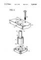
- FIG. 4is an exploded view of a compact fiber positioner that is a component of the compact laser probe of FIG. 1.
- FIG. 1there is illustrated a top view of a compact laser probe 1 that is constructed and operated in accordance with the invention.
- a frame, or probe body 10is fabricated from, preferably, a single piece of material having a low coefficient of thermal expansion. In a presently preferred embodiment of the invention this material is super-invar, although the practice of the invention is not limited to only this particular material.
- the body 10is machined to maintain the stable (dimensional and thermal) characteristics of this presently preferred material. Components contained within the probe body 10 are also comprised, where feasible, of the same material as the probe body 10 in order to minimize any material mismatches with the probe body 10.
- the probe body 10is mounted to a bed 11 using a single 1/4-20 bolt 11a to preserve the dimensional stability of the probe body 10. Approximate dimensions of the probe body 10 are a length of 6.5 cm., a width of 5.0 cm., and a height of 1.5 cm.
- An optical fiber 12transmits laser diode light from a source-detector assembly (not shown) and also transmits combined reference and sample beam light back to the source-detector assembly.
- a source-detector assembly(not shown)
- One suitable embodiment for the source-detector assembly 10is described in commonly assigned U.S. patent application Ser. No. 07/676,144, filed Mar. 27, 1991 now U.S. Pat. No. 5,153,669, entitled “Three Wavelength Optical Measurement Apparatus and Method" by Peter J. de Groot.
- Positioning assembly 14includes a limited motion "ball" 16 for angular adjustment of the fiber 12, a clamp mechanism 18, and a fiber support mandril 20. After the fiber 12 is positioned in the support mandril 20, clamp screws 22 are loosened to permit adjustment of the ball 16. After the fiber 12 angle is correctly adjusted the clamp screws 22 are tightened to secure the ball 16 at the desired position.
- FIG. 4shows an exploded view of a presently preferred embodiment of the fiber positioning assembly 14.
- the fiber support mandril 20is press fit into the limited motion ball 16.
- the mandril 20serves to support the fiber (not shown) and to adjust the angular position of the ball 16.
- the ball 16is fabricated, by example, by milling a ball bearing to form a substantially cylindrical shape.
- the ball 16may also be fabricated by forming a rounded edge on upper and lower edges of a rod.
- the end resultis that a first end 16a is provided with an edge having a radius of curvature, and with a second end 16b having an edge with a radius of curvature.
- the radius of curvature of edges 16a and 16bare typically made equal to one another, although they need not be.
- the positioning fixtureis comprised of the probe body 10, the clamp 18, and the four clamping bolts 22, only one of which is shown in FIG. 4.
- a spherical recess or seat 10ahaving a radius of curvature that is slightly larger than the radius of curvature of the rounded edge 16a, is milled into a surface 10b of the probe body 10.
- a second, similar spherical seat 18ais milled into a surface 18b of the clamp 18 for receiving the edge 16b.
- the clamp 18is preferably fabricated from the same material as the probe body 10 so as to improve the stability of the fiber positioner.
- a result of this mechanical configurationis that the ball 16, and the fiber containing mandril 20, are rotatably coupled to the probe body 10 and are thus adjustably positionable for setting the terminal end of the fiber 12 at a desired angular relationship with the surface 10b. After setting the fiber 12 at a desired angular position, bolts 22 are tightened to fix the ball 16 at the desired position.
- the laser light exiting the terminal end of the fiber 12, indicated by the letter A,is focussed on a sample surface 24, and also on a reference mirror 26, by a lens assembly 28.
- the lens assembly 28includes a super-invar lens cell 30 in which are mounted one or more imaging lenses 32. Focus is adjusted by sliding the lens cell 30 within the probe body 10. After determining a desired position for the lens cell 30, the lens cell 30 is clamped with set screws 34.
- the "working distance" of the laser probe 1is thus fine adjusted by moving the lens cell assembly 28 to focus the light from the fiber 12 onto an optical flat positioned at the desired working distance at which the sample surface 24 will be subsequently positioned. A nominal working distance is 2.5 cm.
- the correct focal positionis determined by monitoring the signal strength at the source/detector assembly, while positioning the lens cell 30, until a maximum signal amplitude is obtained.
- the light exiting the lens cell 30, indicated by the letter B,is split into a reference beam (C) and an object beam (D) by a polarizing beam splitter 36.
- the reference beam (C)is reflected from a fold mirror 38 to the reference mirror 26.
- the angle of the fold mirror 38adjusted with pitch adjustment/locking screws 40 and roll adjustment/locking screws 42. These screws (40, 42) connect a mirror support 44 to the probe body 10.
- the reference mirror 26is mounted on a modulation stage 46.
- the modulation stage 46is supported upon a low-voltage piezoelectric stack 48 mounted within a tube 50 comprised of, preferably, the same material as the probe body 10.
- the piezoelectric stack 50is coupled via wiring 52 to an electronics package 54 which is connected to a remote power supply (not shown) by cable assembly 56.
- the reference beam path lengthis adjusted by moving the piezoelectric stack 48 to a provide a focal spot of the reference beam, with a nominal path length of 2.5 cm.
- the signal at the source detector assemblyis monitored and the reference beam focus is achieved when this signal is at a maximum.
- the sample beamis preferably blocked during this adjustment.
- light reflected from the reference mirror 26 and from the surface of the sample 24is recombined in the polarizing beam splitter 36 and coupled into the fiber 12 by the lens assembly 28.
- the combined lightis then interferometrically compared at the source/detector assembly so as to determine a displacement of the sample surface 24, relative to the beamsplitter 36. This displacement is indicative of a range to, or a characteristic of, the sample surface 24.
- the low-voltage piezoelectric stack 50 modulator for the reference mirror 26is controlled by two signals: a dc bias signal and an ac modulation signal.
- the dc bias signalcontrols a nominal length of the piezoelectric stack 48 while the ac modulation signal controls a range of motion of the stack 48 about the nominal length.
- One suitable frequency for the ac modulation signalis 5 Hz. Fine focus adjustments for the reference channel are made by adjusting the dc bias voltage and, hence, the nominal length of the piezoelectric stack 48.
- the piezoelectric stack control electronics 54employs the output of a strain gauge 58 on the piezoelectric stack 48 modulator to maintain the motion linear with ac modulation voltage.
- the electronics 54use the output of a similar strain gauge 60 located on the super-invar probe body 10 to adjust the dc bias voltage applied to the piezoelectric stack 48 modulator to simultaneously compensate for any length changes in the probe body 10. This technique stabilizes the piezoelectric material of the stack 48 to the super-invar material of the probe body 10, thereby athermalizing the reference beam path.
- Signals from the control electronics 54are transmitted to the low noise piezoelectric power supplies via the electrical cable assembly 56.
- the piezoelectric stack 48 modulatoris controlled with the first strain gauge 58 attached to the piezoelectric stack 48 and with the second strain gauge 60 that is attached to the central rib 10a of the probe body 10.
- This techniqueprovides for the athermalization of the piezoelectric stack 48 in that the second strain gauge 60, attached to the super invar probe body 10, is used to provide a dc offset to the ac modulation voltage applied to the piezoelectric stack 48.
- the presently preferred material for the probe body 10is super-invar, which has a negative coefficient of thermal expansion
- the dc bias voltagedecreases as temperature increases. If the selected material has a positive coefficient of thermal expansion, the dc bias voltage is caused to increase with increasing temperature.
- the dc offset voltagechanges the zero-modulation length of the piezoelectric stack 48 such that the piezoelectric material of the stack 48 "behaves" in a fashion similar to the super invar of the probe body 10.
- the waveform of FIG. 2shows an exemplary command voltage that drives the piezoelectric stack 48.
- the command voltageis nominally a saw tooth waveform having a frequency of, for example, 5 Hz.
- the closed loop control system of FIG. 3drives the piezoelectric stack 48.
- the piezoelectric stack command position voltageis applied to an input terminal and, through a resistor R1, to an error amplifier A1.
- Error amplifier A1includes a potentiometer R2 for adjusting the servo gain of the servo loop.
- the output of the error amplifieris applied through resistor R3 to a power amplifier A2.
- the output of amplifier A2is a current that is proportional to the output of the error amplifier A1. This current is applied to the piezoelectric stack 48 which integrates same and which changes its position (length) in response to the sawtooth drive signal.
- the piezoelectric stack 48is coupled to ground through a resistor R4.
- each strain gauge (58, 60)has a nominal, unstrained, resistance of 350 Ohms.
- An input node of each of the strain gaugesis coupled to a voltage reference (VR) that provides a positive reference voltage to an input node of the strain gauge 58 and an equal, but opposite, potential to an input node of the strain gauge 60.
- An instrumentation amplifier A3is coupled to a node that is connected between an output node of each of the strain gauges 58 and 60.
- a second input to the amplifier A3is coupled to a reference voltage that is output by VR.
- This reference voltageis nominally zero volts.
- A3amplifies a difference voltage obtained from the 1/2 bridge circuit formed by strain gauges 58 and 60.
- the magnitude of the difference voltageis a function of the difference in strain applied to the strain gauges 58 and 60 due to the commanded change in length of the piezoelectric stack 48 and, in accordance with an aspect of the invention, a thermal expansion or contraction of the super-invar body 10.
- This error voltageis coupled to amplifier A4.
- A4includes a potentiometer R5 for adjusting the feedback gain and a potentiometer R6 for adjusting the offset (zero).
- the output of amplifier A4is coupled to the input of amplifier A1 for closing the servo loop around the mirror 26 that is coupled to the piezoelectric stack 48.
- This techniqueeffectively athermalizes the probe 1, in that any expansion or contraction of the super-invar is matched by the piezoelectric stack 48, yielding a net zero change in the non-common beam path lengths.
- This athermalization techniquesubstantially reduces thermal drift uncertainties in the profilometry data.
- the open cell construction of the compact probe 1also beneficially reduces atmospheric effect uncertainties in the profilometry data, in that both reference beam and sample beam paths have common atmospheres.
Landscapes
- Physics & Mathematics (AREA)
- General Physics & Mathematics (AREA)
- Engineering & Computer Science (AREA)
- Multimedia (AREA)
- Radar, Positioning & Navigation (AREA)
- Remote Sensing (AREA)
- Length Measuring Devices By Optical Means (AREA)
- Instruments For Measurement Of Length By Optical Means (AREA)
Abstract
Description
Claims (21)
Priority Applications (7)
| Application Number | Priority Date | Filing Date | Title |
|---|---|---|---|
| US07/834,758US5239366A (en) | 1992-02-12 | 1992-02-12 | Compact laser probe for profilometry |
| IL104641AIL104641A0 (en) | 1992-02-12 | 1993-02-07 | Compact laser probe for profilometry |
| EP93300986AEP0556041B1 (en) | 1992-02-12 | 1993-02-11 | Compact laser probe for profilometry |
| KR1019930001875AKR930018259A (en) | 1992-02-12 | 1993-02-11 | Compact laser probe for profilometry |
| DE69310947TDE69310947T2 (en) | 1992-02-12 | 1993-02-11 | Compact laser probe for profilometry |
| JP5024547AJP2505360B2 (en) | 1992-02-12 | 1993-02-12 | Compact laser probe for profile measurement |
| US08/021,711US5448662A (en) | 1992-02-12 | 1993-02-24 | Apparatus for coupling an optical fiber to a structure at a desired angle |
Applications Claiming Priority (1)
| Application Number | Priority Date | Filing Date | Title |
|---|---|---|---|
| US07/834,758US5239366A (en) | 1992-02-12 | 1992-02-12 | Compact laser probe for profilometry |
Related Child Applications (1)
| Application Number | Title | Priority Date | Filing Date |
|---|---|---|---|
| US08/021,711DivisionUS5448662A (en) | 1992-02-12 | 1993-02-24 | Apparatus for coupling an optical fiber to a structure at a desired angle |
Publications (1)
| Publication Number | Publication Date |
|---|---|
| US5239366Atrue US5239366A (en) | 1993-08-24 |
Family
ID=25267734
Family Applications (2)
| Application Number | Title | Priority Date | Filing Date |
|---|---|---|---|
| US07/834,758Expired - LifetimeUS5239366A (en) | 1992-02-12 | 1992-02-12 | Compact laser probe for profilometry |
| US08/021,711Expired - Fee RelatedUS5448662A (en) | 1992-02-12 | 1993-02-24 | Apparatus for coupling an optical fiber to a structure at a desired angle |
Family Applications After (1)
| Application Number | Title | Priority Date | Filing Date |
|---|---|---|---|
| US08/021,711Expired - Fee RelatedUS5448662A (en) | 1992-02-12 | 1993-02-24 | Apparatus for coupling an optical fiber to a structure at a desired angle |
Country Status (6)
| Country | Link |
|---|---|
| US (2) | US5239366A (en) |
| EP (1) | EP0556041B1 (en) |
| JP (1) | JP2505360B2 (en) |
| KR (1) | KR930018259A (en) |
| DE (1) | DE69310947T2 (en) |
| IL (1) | IL104641A0 (en) |
Cited By (9)
| Publication number | Priority date | Publication date | Assignee | Title |
|---|---|---|---|---|
| US5365140A (en)* | 1992-12-22 | 1994-11-15 | Nec Corporation | Piezoelectric actuator having strain gage |
| US5448662A (en)* | 1992-02-12 | 1995-09-05 | Hughes Aircraft Company | Apparatus for coupling an optical fiber to a structure at a desired angle |
| US5831736A (en)* | 1996-08-29 | 1998-11-03 | Washington University | Method and apparatus for generating a three-dimensional topographical image of a microscopic specimen |
| US5895927A (en)* | 1995-06-30 | 1999-04-20 | The United States Of America As Represented By The Secretary Of The Air Force | Electro-optic, noncontact, interior cross-sectional profiler |
| US5966213A (en)* | 1997-07-11 | 1999-10-12 | Bridgestone Sports Co., Ltd. | Method and apparatus for measuring the surface shape of a golf ball |
| US20050182592A1 (en)* | 2001-10-23 | 2005-08-18 | Aikens David M. | Evolution of library data sets |
| US20120147356A1 (en)* | 2010-12-13 | 2012-06-14 | Southwest Research Institute | White Light Optical Profilometer for Measuring Complex Surfaces |
| RU2650840C1 (en)* | 2016-12-27 | 2018-04-17 | Общество с ограниченной ответственностью "Спецдортехника" | Laser profilometer for determining geometric parameters of surface profile |
| US11454537B2 (en) | 2018-10-31 | 2022-09-27 | Industrial Technology Research Institute | Optical measurement stability control system |
Families Citing this family (40)
| Publication number | Priority date | Publication date | Assignee | Title |
|---|---|---|---|---|
| EP0708347A1 (en)* | 1994-10-21 | 1996-04-24 | Hewlett-Packard GmbH | Apparatus for adjustment, attenuating device, coupling device and filtering device |
| DE4445642A1 (en)* | 1994-12-21 | 1996-06-27 | Marco Systemanalyse Entw | Piezo actuator drive or adjustment element |
| US5659652A (en)* | 1995-09-29 | 1997-08-19 | D'entremont; Joseph P. | Support system for rapid assembly of component infrastructures |
| DE19615918C2 (en)* | 1995-12-07 | 1999-12-09 | Walu Labortechnik Gmbh | Repeater pipette |
| US5661843A (en)* | 1996-01-30 | 1997-08-26 | Rifocs Corporation | Fiber optic probe |
| US7206623B2 (en)* | 2000-05-02 | 2007-04-17 | Sensys Medical, Inc. | Optical sampling interface system for in vivo measurement of tissue |
| US7383069B2 (en)* | 1997-08-14 | 2008-06-03 | Sensys Medical, Inc. | Method of sample control and calibration adjustment for use with a noninvasive analyzer |
| US6415167B1 (en) | 2000-05-02 | 2002-07-02 | Instrumentation Metrics, Inc. | Fiber optic probe placement guide |
| US5924234A (en)* | 1997-11-20 | 1999-07-20 | Trijicon, Inc. | Optical sighting device |
| US7606608B2 (en)* | 2000-05-02 | 2009-10-20 | Sensys Medical, Inc. | Optical sampling interface system for in-vivo measurement of tissue |
| US20060211931A1 (en)* | 2000-05-02 | 2006-09-21 | Blank Thomas B | Noninvasive analyzer sample probe interface method and apparatus |
| US7519406B2 (en)* | 2004-04-28 | 2009-04-14 | Sensys Medical, Inc. | Noninvasive analyzer sample probe interface method and apparatus |
| US20070179367A1 (en)* | 2000-05-02 | 2007-08-02 | Ruchti Timothy L | Method and Apparatus for Noninvasively Estimating a Property of an Animal Body Analyte from Spectral Data |
| US20020135767A1 (en)* | 2001-03-16 | 2002-09-26 | Richard Jenkin A. | Optical alignment element method |
| US6928225B2 (en)* | 2001-04-03 | 2005-08-09 | Schott Glas | Method and assembly for mounting at least one optical fiber |
| US6847450B2 (en)* | 2001-07-27 | 2005-01-25 | Oplink Communications, Inc. | System and method for optical multiplexing and/or demultiplexing |
| US6798523B2 (en)* | 2001-12-04 | 2004-09-28 | Honeywell International Inc. | Sensor and method for detecting fiber optic faults |
| US7697966B2 (en)* | 2002-03-08 | 2010-04-13 | Sensys Medical, Inc. | Noninvasive targeting system method and apparatus |
| US20070149868A1 (en)* | 2002-03-08 | 2007-06-28 | Blank Thomas B | Method and Apparatus for Photostimulation Enhanced Analyte Property Estimation |
| US8504128B2 (en)* | 2002-03-08 | 2013-08-06 | Glt Acquisition Corp. | Method and apparatus for coupling a channeled sample probe to tissue |
| US20050187439A1 (en)* | 2003-03-07 | 2005-08-25 | Blank Thomas B. | Sampling interface system for in-vivo estimation of tissue analyte concentration |
| US20050054908A1 (en)* | 2003-03-07 | 2005-03-10 | Blank Thomas B. | Photostimulation method and apparatus in combination with glucose determination |
| JP4189322B2 (en)* | 2002-03-08 | 2008-12-03 | センシス メディカル インク | Compact instrument for non-invasive measurement of glucose by near infrared spectroscopy |
| US8718738B2 (en)* | 2002-03-08 | 2014-05-06 | Glt Acquisition Corp. | Method and apparatus for coupling a sample probe with a sample site |
| DE10236755B4 (en)* | 2002-08-10 | 2005-04-14 | Sms Meer Gmbh | Device for measuring the wall thickness of a pipe in a tube rolling mill |
| US6807742B2 (en)* | 2002-09-06 | 2004-10-26 | Trijicon, Inc. | Reflex sight with multiple power sources for reticle |
| CA2512870A1 (en)* | 2003-01-23 | 2004-08-12 | Corning Incorporated | Lensed fiber having small form factor and method of making same |
| US20050159656A1 (en)* | 2003-03-07 | 2005-07-21 | Hockersmith Linda J. | Method and apparatus for presentation of noninvasive glucose concentration information |
| US20070234300A1 (en)* | 2003-09-18 | 2007-10-04 | Leake David W | Method and Apparatus for Performing State-Table Driven Regression Testing |
| US20080033275A1 (en)* | 2004-04-28 | 2008-02-07 | Blank Thomas B | Method and Apparatus for Sample Probe Movement Control |
| US8868147B2 (en)* | 2004-04-28 | 2014-10-21 | Glt Acquisition Corp. | Method and apparatus for controlling positioning of a noninvasive analyzer sample probe |
| US20060217602A1 (en)* | 2005-03-04 | 2006-09-28 | Alan Abul-Haj | Method and apparatus for noninvasive targeting |
| EP1976241B1 (en) | 2007-03-26 | 2011-01-05 | Research In Motion Limited | System and method for providing a user interface that facilitates user selection of a communication line for an outgoing call on a mobile device |
| DE602007003187D1 (en) | 2007-03-26 | 2009-12-24 | Research In Motion Ltd | A system and method for providing call function icons on a user interface that enables user selection of a communication line for an outgoing call on a mobile terminal |
| US20090036759A1 (en)* | 2007-08-01 | 2009-02-05 | Ault Timothy E | Collapsible noninvasive analyzer method and apparatus |
| WO2009076564A1 (en)* | 2007-12-11 | 2009-06-18 | Menard, Inc. | Programmable strain gauge amplifier |
| TWI473963B (en)* | 2011-03-04 | 2015-02-21 | Univ Nat Formosa | One-dimensional laser-scanning profilometer and method |
| US20150146201A1 (en)* | 2013-05-02 | 2015-05-28 | Michael Burka | Optical probe with extended working distance |
| CN104330005A (en)* | 2014-10-28 | 2015-02-04 | 重庆佳速汽车零部件有限公司 | Checking tool for lever end position of gear lever |
| CN104330008B (en)* | 2014-11-24 | 2016-08-24 | 沈阳黎明航空发动机(集团)有限责任公司 | A kind of rocking arm set component dimension measuring device and measuring method |
Citations (4)
| Publication number | Priority date | Publication date | Assignee | Title |
|---|---|---|---|---|
| US4758065A (en)* | 1985-03-08 | 1988-07-19 | Mechanical Technology Incorporated | Fiber optic sensor probe |
| US4796994A (en)* | 1985-08-13 | 1989-01-10 | Lars Bager | Method and apparatus for measuring variations in distances |
| US5042949A (en)* | 1989-03-17 | 1991-08-27 | Greenberg Jeffrey S | Optical profiler for films and substrates |
| US5153669A (en)* | 1991-03-27 | 1992-10-06 | Hughes Danbury Optical Systems, Inc. | Three wavelength optical measurement apparatus and method |
Family Cites Families (19)
| Publication number | Priority date | Publication date | Assignee | Title |
|---|---|---|---|---|
| DE2922937C2 (en)* | 1979-06-01 | 1981-07-02 | Fabeg Gmbh, 7518 Bretten | Cable coupling for the automatic coupling of electrical heating and / or control current lines as well as light guides for the optical transmission of commands, in particular for rail vehicles |
| SE445778B (en)* | 1980-04-03 | 1986-07-14 | Gerhard Westerberg | COMPENSATION DEVICE FOR A LASER INTERFEROMETER |
| JPS6078410A (en)* | 1983-10-05 | 1985-05-04 | Fujitsu Ltd | Adjustment type optical connector |
| JPS6124710U (en)* | 1984-07-19 | 1986-02-14 | 株式会社 高橋製作所 | Temperature compensation device in reflecting telescope |
| US4639139A (en)* | 1985-09-27 | 1987-01-27 | Wyko Corporation | Optical profiler using improved phase shifting interferometry |
| US4667922A (en)* | 1985-11-08 | 1987-05-26 | The United States Of America As Represented By The United States Department Of Energy | Support assembly having three dimension position adjustment capabilities |
| US4850536A (en)* | 1986-10-14 | 1989-07-25 | Arimitsu Industry Co., Ltd. | Liquid ejection apparatus |
| US4814948A (en)* | 1987-07-02 | 1989-03-21 | Yasuo Hasegawa | Light-emitting-end mounting mechanism in optical display panel |
| JPH0196610A (en)* | 1987-10-08 | 1989-04-14 | Sumitomo Electric Ind Ltd | Optical coupling device |
| US5147348A (en)* | 1988-03-18 | 1992-09-15 | Eli Lilly And Company | Optical fiber rotational connector |
| JPH0216442A (en)* | 1988-07-04 | 1990-01-19 | Mitsubishi Motors Corp | oxygen sensor |
| US4909589A (en)* | 1988-12-11 | 1990-03-20 | Morris Robert K | Rotatable photonic coupling |
| JPH02308109A (en)* | 1989-05-23 | 1990-12-21 | Nec Corp | Structure for fixing optical module |
| JP2959576B2 (en)* | 1990-02-07 | 1999-10-06 | 富士通株式会社 | Optical member fixing structure |
| IT1239223B (en)* | 1990-02-20 | 1993-09-28 | Pirelli Cavi Spa | ADJUSTABLE OPTICAL CONNECTOR FOR CONNECTION OF OPTICAL FIBERS TO DISCRETE OPTICAL COMPONENTS AND SENSOR USING ONE OR MORE ADJUSTABLE CONNECTORS |
| US5138676A (en)* | 1990-06-15 | 1992-08-11 | Aster Corporation | Miniature fiberoptic bend device and method |
| JPH0486705A (en)* | 1990-07-31 | 1992-03-19 | Canon Inc | Light guide |
| US5293438A (en)* | 1991-09-21 | 1994-03-08 | Namiki Precision Jewel Co., Ltd. | Microlensed optical terminals and optical system equipped therewith, and methods for their manufacture, especially an optical coupling method and optical coupler for use therewith |
| US5239366A (en)* | 1992-02-12 | 1993-08-24 | Huges Aircraft Company | Compact laser probe for profilometry |
- 1992
- 1992-02-12USUS07/834,758patent/US5239366A/ennot_activeExpired - Lifetime
- 1993
- 1993-02-07ILIL104641Apatent/IL104641A0/enunknown
- 1993-02-11KRKR1019930001875Apatent/KR930018259A/ennot_activeCeased
- 1993-02-11EPEP93300986Apatent/EP0556041B1/ennot_activeExpired - Lifetime
- 1993-02-11DEDE69310947Tpatent/DE69310947T2/ennot_activeExpired - Fee Related
- 1993-02-12JPJP5024547Apatent/JP2505360B2/ennot_activeExpired - Lifetime
- 1993-02-24USUS08/021,711patent/US5448662A/ennot_activeExpired - Fee Related
Patent Citations (4)
| Publication number | Priority date | Publication date | Assignee | Title |
|---|---|---|---|---|
| US4758065A (en)* | 1985-03-08 | 1988-07-19 | Mechanical Technology Incorporated | Fiber optic sensor probe |
| US4796994A (en)* | 1985-08-13 | 1989-01-10 | Lars Bager | Method and apparatus for measuring variations in distances |
| US5042949A (en)* | 1989-03-17 | 1991-08-27 | Greenberg Jeffrey S | Optical profiler for films and substrates |
| US5153669A (en)* | 1991-03-27 | 1992-10-06 | Hughes Danbury Optical Systems, Inc. | Three wavelength optical measurement apparatus and method |
Cited By (11)
| Publication number | Priority date | Publication date | Assignee | Title |
|---|---|---|---|---|
| US5448662A (en)* | 1992-02-12 | 1995-09-05 | Hughes Aircraft Company | Apparatus for coupling an optical fiber to a structure at a desired angle |
| US5365140A (en)* | 1992-12-22 | 1994-11-15 | Nec Corporation | Piezoelectric actuator having strain gage |
| US5895927A (en)* | 1995-06-30 | 1999-04-20 | The United States Of America As Represented By The Secretary Of The Air Force | Electro-optic, noncontact, interior cross-sectional profiler |
| US5831736A (en)* | 1996-08-29 | 1998-11-03 | Washington University | Method and apparatus for generating a three-dimensional topographical image of a microscopic specimen |
| US5966213A (en)* | 1997-07-11 | 1999-10-12 | Bridgestone Sports Co., Ltd. | Method and apparatus for measuring the surface shape of a golf ball |
| US20050182592A1 (en)* | 2001-10-23 | 2005-08-18 | Aikens David M. | Evolution of library data sets |
| US8543557B2 (en)* | 2001-10-23 | 2013-09-24 | Kla-Tencor Corporation | Evolution of library data sets |
| US20120147356A1 (en)* | 2010-12-13 | 2012-06-14 | Southwest Research Institute | White Light Optical Profilometer for Measuring Complex Surfaces |
| US8593644B2 (en)* | 2010-12-13 | 2013-11-26 | Southwest Research Institute | White light optical profilometer for measuring complex surfaces |
| RU2650840C1 (en)* | 2016-12-27 | 2018-04-17 | Общество с ограниченной ответственностью "Спецдортехника" | Laser profilometer for determining geometric parameters of surface profile |
| US11454537B2 (en) | 2018-10-31 | 2022-09-27 | Industrial Technology Research Institute | Optical measurement stability control system |
Also Published As
| Publication number | Publication date |
|---|---|
| JP2505360B2 (en) | 1996-06-05 |
| EP0556041A2 (en) | 1993-08-18 |
| KR930018259A (en) | 1993-09-21 |
| DE69310947T2 (en) | 1997-12-18 |
| JPH0611317A (en) | 1994-01-21 |
| EP0556041A3 (en) | 1993-11-10 |
| DE69310947D1 (en) | 1997-07-03 |
| EP0556041B1 (en) | 1997-05-28 |
| IL104641A0 (en) | 1993-06-10 |
| US5448662A (en) | 1995-09-05 |
Similar Documents
| Publication | Publication Date | Title |
|---|---|---|
| US5239366A (en) | Compact laser probe for profilometry | |
| US6612160B2 (en) | Apparatus and method for isolating and measuring movement in metrology apparatus | |
| US3786332A (en) | Micro positioning apparatus | |
| US6438856B1 (en) | Apparatus for fine positioning of a component, and coordinate measuring machine having an apparatus for fine positioning of a component | |
| US5140242A (en) | Servo guided stage system | |
| US6556364B2 (en) | Apparatus, system, and method for precision positioning and alignment of a lens in an optical system | |
| JP3184825B2 (en) | Apparatus and method for accurately adjusting the angular position of an optical device | |
| CA1295039C (en) | Galvanometric optical scanning system | |
| JPS6324211A (en) | Opto-lithographic apparatus and control of image formation characteristic in lens system thereof | |
| Jusko et al. | Design and three dimensional calibration of a measuring scanning tunneling microscope for metrological applications | |
| US20120079633A1 (en) | Apparatus and Method for Isolating and Measuring Movement in Metrology Apparatus | |
| US5446547A (en) | Combination of motorized and piezoelectric translation for long-range vertical scanning interferometry | |
| US4309618A (en) | Precision optical distance measurement | |
| US4674882A (en) | Precision optical displacement measuring instrument using servo controlled fiber optic sensor | |
| Heeren et al. | An optical system to measure the end effector position for on-line control purposes | |
| JPH05157554A (en) | Probe microscope incorporated with optical micsroscope | |
| Becker et al. | Translation stage for a scanning x‐ray optical interferometer | |
| US4994661A (en) | Optical two-dimensional servo-loop for laser beam stabilization and/or position encoding | |
| US20070171624A1 (en) | Optical beam steering and sampling apparatus and method | |
| EP0683414A1 (en) | Optical scanning apparatus | |
| KR100302179B1 (en) | 3- axes stage apparatus using kinematic joint | |
| JPH06281445A (en) | Scanner system | |
| Thwaite et al. | A 10 mm measuring machine based on a compensated laser interferometer | |
| JP3256556B2 (en) | Positioning device | |
| Atherton et al. | The Digital Piezo Transducer |
Legal Events
| Date | Code | Title | Description |
|---|---|---|---|
| AS | Assignment | Owner name:HUGHES AIRCRAFT COMPANY A DELAWARE CORPORATION Free format text:ASSIGNMENT OF ASSIGNORS INTEREST.;ASSIGNOR:KITTELL, DAVID H.;REEL/FRAME:006084/0369 Effective date:19920131 Owner name:HUGHES AIRCRAFT COMPANY A CORPORATION OF DELAWA Free format text:ASSIGNMENT OF ASSIGNORS INTEREST.;ASSIGNOR:DE GROOT, PETER J.;REEL/FRAME:006084/0372 Effective date:19920127 Owner name:HUGHES AIRCRAFT COMPANY A CORPORATION OF DELAWA Free format text:ASSIGNMENT OF ASSIGNORS INTEREST.;ASSIGNOR:HAYES, GUY H.;REEL/FRAME:006084/0366 Effective date:19920212 | |
| STCF | Information on status: patent grant | Free format text:PATENTED CASE | |
| FPAY | Fee payment | Year of fee payment:4 | |
| AS | Assignment | Owner name:HE HOLDINGS, INC., A CORP. OF DELAWARE, CALIFORNIA Free format text:CHANGE OF NAME;ASSIGNOR:HUGHES AIRCRAFT COMPANY, A CORP. OF DELAWARE;REEL/FRAME:011035/0961 Effective date:19951208 Owner name:RAYTHEON COMPANY, MASSACHUSETTS Free format text:MERGER;ASSIGNOR:HE HOLDINGS, INC.;REEL/FRAME:011035/0993 Effective date:19971217 | |
| AS | Assignment | Owner name:RAYTHEON OPTICAL SYSTEMS, INC., CONNECTICUT Free format text:CHANGE OF NAME;ASSIGNOR:HUGHES DANBURY OPTICAL SYSTEMS;REEL/FRAME:011164/0410 Effective date:19991217 Owner name:RAYTHEON COMPANY, A CORPORATION OF DELAWARE, MASSA Free format text:MERGER;ASSIGNOR:RAYTHEON OPTICAL SYSTEMS, INC., A CORPORATION OF DELAWARE;REEL/FRAME:011164/0492 Effective date:19981229 | |
| FPAY | Fee payment | Year of fee payment:8 | |
| AS | Assignment | Owner name:B.F. GOODRICH COMPANY, THE, NORTH CAROLINA Free format text:ASSIGNMENT OF ASSIGNORS INTEREST;ASSIGNOR:RAYTHEON COMPANY;REEL/FRAME:011497/0102 Effective date:20001227 | |
| FEPP | Fee payment procedure | Free format text:PAYOR NUMBER ASSIGNED (ORIGINAL EVENT CODE: ASPN); ENTITY STATUS OF PATENT OWNER: LARGE ENTITY | |
| FPAY | Fee payment | Year of fee payment:12 |