US5238001A - Ambulatory patient monitoring system having multiple monitoring units and optical communications therebetween - Google Patents
Ambulatory patient monitoring system having multiple monitoring units and optical communications therebetweenDownload PDFInfo
- Publication number
- US5238001A US5238001AUS07/790,500US79050091AUS5238001AUS 5238001 AUS5238001 AUS 5238001AUS 79050091 AUS79050091 AUS 79050091AUS 5238001 AUS5238001 AUS 5238001A
- Authority
- US
- United States
- Prior art keywords
- microprocessor
- coupled
- monitoring
- monitoring system
- diagnostic parameter
- Prior art date
- Legal status (The legal status is an assumption and is not a legal conclusion. Google has not performed a legal analysis and makes no representation as to the accuracy of the status listed.)
- Expired - Fee Related
Links
- 0CCCC(CC1CC2[C@@](*)CCC(CC3)[C@]3CCC2)C2=C1C=CC2=CCCChemical compoundCCCC(CC1CC2[C@@](*)CCC(CC3)[C@]3CCC2)C2=C1C=CC2=CCC0.000description1
Images


Classifications
- A—HUMAN NECESSITIES
- A61—MEDICAL OR VETERINARY SCIENCE; HYGIENE
- A61B—DIAGNOSIS; SURGERY; IDENTIFICATION
- A61B5/00—Measuring for diagnostic purposes; Identification of persons
- A61B5/02—Detecting, measuring or recording for evaluating the cardiovascular system, e.g. pulse, heart rate, blood pressure or blood flow
- A61B5/021—Measuring pressure in heart or blood vessels
- A61B5/022—Measuring pressure in heart or blood vessels by applying pressure to close blood vessels, e.g. against the skin; Ophthalmodynamometers
- A61B5/0225—Measuring pressure in heart or blood vessels by applying pressure to close blood vessels, e.g. against the skin; Ophthalmodynamometers the pressure being controlled by electric signals, e.g. derived from Korotkoff sounds
- A—HUMAN NECESSITIES
- A61—MEDICAL OR VETERINARY SCIENCE; HYGIENE
- A61B—DIAGNOSIS; SURGERY; IDENTIFICATION
- A61B5/00—Measuring for diagnostic purposes; Identification of persons
- A61B5/02—Detecting, measuring or recording for evaluating the cardiovascular system, e.g. pulse, heart rate, blood pressure or blood flow
- A61B5/0205—Simultaneously evaluating both cardiovascular conditions and different types of body conditions, e.g. heart and respiratory condition
- A—HUMAN NECESSITIES
- A61—MEDICAL OR VETERINARY SCIENCE; HYGIENE
- A61B—DIAGNOSIS; SURGERY; IDENTIFICATION
- A61B5/00—Measuring for diagnostic purposes; Identification of persons
- A61B5/02—Detecting, measuring or recording for evaluating the cardiovascular system, e.g. pulse, heart rate, blood pressure or blood flow
- A61B5/021—Measuring pressure in heart or blood vessels
- A61B5/022—Measuring pressure in heart or blood vessels by applying pressure to close blood vessels, e.g. against the skin; Ophthalmodynamometers
- A61B5/02208—Measuring pressure in heart or blood vessels by applying pressure to close blood vessels, e.g. against the skin; Ophthalmodynamometers using the Korotkoff method
- A—HUMAN NECESSITIES
- A61—MEDICAL OR VETERINARY SCIENCE; HYGIENE
- A61B—DIAGNOSIS; SURGERY; IDENTIFICATION
- A61B5/00—Measuring for diagnostic purposes; Identification of persons
- A61B5/02—Detecting, measuring or recording for evaluating the cardiovascular system, e.g. pulse, heart rate, blood pressure or blood flow
- A61B5/021—Measuring pressure in heart or blood vessels
- A61B5/022—Measuring pressure in heart or blood vessels by applying pressure to close blood vessels, e.g. against the skin; Ophthalmodynamometers
- A61B5/02225—Measuring pressure in heart or blood vessels by applying pressure to close blood vessels, e.g. against the skin; Ophthalmodynamometers using the oscillometric method
- A—HUMAN NECESSITIES
- A61—MEDICAL OR VETERINARY SCIENCE; HYGIENE
- A61B—DIAGNOSIS; SURGERY; IDENTIFICATION
- A61B5/00—Measuring for diagnostic purposes; Identification of persons
- A61B5/24—Detecting, measuring or recording bioelectric or biomagnetic signals of the body or parts thereof
- A61B5/316—Modalities, i.e. specific diagnostic methods
- A61B5/318—Heart-related electrical modalities, e.g. electrocardiography [ECG]
- A61B5/333—Recording apparatus specially adapted therefor
- A61B5/335—Recording apparatus specially adapted therefor using integrated circuit memory devices
- A—HUMAN NECESSITIES
- A61—MEDICAL OR VETERINARY SCIENCE; HYGIENE
- A61B—DIAGNOSIS; SURGERY; IDENTIFICATION
- A61B5/00—Measuring for diagnostic purposes; Identification of persons
- A61B5/74—Details of notification to user or communication with user or patient; User input means
- A61B5/7475—User input or interface means, e.g. keyboard, pointing device, joystick
- A—HUMAN NECESSITIES
- A61—MEDICAL OR VETERINARY SCIENCE; HYGIENE
- A61B—DIAGNOSIS; SURGERY; IDENTIFICATION
- A61B7/00—Instruments for auscultation
- A61B7/02—Stethoscopes
- A61B7/04—Electric stethoscopes
- A61B7/045—Detection of Korotkoff sounds
- A—HUMAN NECESSITIES
- A61—MEDICAL OR VETERINARY SCIENCE; HYGIENE
- A61B—DIAGNOSIS; SURGERY; IDENTIFICATION
- A61B2560/00—Constructional details of operational features of apparatus; Accessories for medical measuring apparatus
- A61B2560/04—Constructional details of apparatus
- A—HUMAN NECESSITIES
- A61—MEDICAL OR VETERINARY SCIENCE; HYGIENE
- A61B—DIAGNOSIS; SURGERY; IDENTIFICATION
- A61B5/00—Measuring for diagnostic purposes; Identification of persons
- A61B5/72—Signal processing specially adapted for physiological signals or for diagnostic purposes
- A61B5/7232—Signal processing specially adapted for physiological signals or for diagnostic purposes involving compression of the physiological signal, e.g. to extend the signal recording period
- A—HUMAN NECESSITIES
- A61—MEDICAL OR VETERINARY SCIENCE; HYGIENE
- A61B—DIAGNOSIS; SURGERY; IDENTIFICATION
- A61B5/00—Measuring for diagnostic purposes; Identification of persons
- A61B5/72—Signal processing specially adapted for physiological signals or for diagnostic purposes
- A61B5/7271—Specific aspects of physiological measurement analysis
- A61B5/7285—Specific aspects of physiological measurement analysis for synchronizing or triggering a physiological measurement or image acquisition with a physiological event or waveform, e.g. an ECG signal
- Y—GENERAL TAGGING OF NEW TECHNOLOGICAL DEVELOPMENTS; GENERAL TAGGING OF CROSS-SECTIONAL TECHNOLOGIES SPANNING OVER SEVERAL SECTIONS OF THE IPC; TECHNICAL SUBJECTS COVERED BY FORMER USPC CROSS-REFERENCE ART COLLECTIONS [XRACs] AND DIGESTS
- Y10—TECHNICAL SUBJECTS COVERED BY FORMER USPC
- Y10S—TECHNICAL SUBJECTS COVERED BY FORMER USPC CROSS-REFERENCE ART COLLECTIONS [XRACs] AND DIGESTS
- Y10S128/00—Surgery
- Y10S128/90—Blood pressure recorder
- Y—GENERAL TAGGING OF NEW TECHNOLOGICAL DEVELOPMENTS; GENERAL TAGGING OF CROSS-SECTIONAL TECHNOLOGIES SPANNING OVER SEVERAL SECTIONS OF THE IPC; TECHNICAL SUBJECTS COVERED BY FORMER USPC CROSS-REFERENCE ART COLLECTIONS [XRACs] AND DIGESTS
- Y10—TECHNICAL SUBJECTS COVERED BY FORMER USPC
- Y10S—TECHNICAL SUBJECTS COVERED BY FORMER USPC CROSS-REFERENCE ART COLLECTIONS [XRACs] AND DIGESTS
- Y10S128/00—Surgery
- Y10S128/908—Patient protection from electric shock
Definitions
- This inventiondirects itself to ambulatory monitoring systems for measuring and storing diagnostic parameters.
- this inventiondirects itself to a modular monitoring system, wherein modular monitoring units can be used either independently of one another, or utilized together with at least one module communicating to another through an optical interface.
- this inventiondirects itself to a system wherein the patient's ECG waveform is monitored and analyzed to identify particular abnormalities, both the ECG waveform and analysis data being stored in a non-volatile memory.
- this systemis directed to a blood pressure monitoring module for taking measurements responsive to a selectively variable repetition rate, selectively actuated for predetermined time intervals, and at times triggered by the ECG monitoring unit, when both are being utilized.
- this inventionpertains to an ambulatory monitoring system wherein each of the monitoring unit modules includes a serial interface for coupling with a personal-type computer to allow the physician to program predetermined parameters, observe measurements in real time, and download measurement data stored in the memory of each of the modules. Further, this invention directs itself to ambulatory monitoring units having means for conserving power to enable the units to operate for over twenty-four hours on battery power. Such power conserving means may take the form of a system is vary the operational speed of the monitoring unit's microprocessor, or alternately shutting down the operation of the unit's microprocessor for predetermined periods of time.
- An ambulatory patient monitoring systemfor measuring and storing predetermined diagnostic parameters of a patient.
- the ambulatory patient monitoring systemincludes a first monitoring unit for independently measuring and storing a predetermined first diagnostic parameter of a first patient responsive to a first control algorithm.
- the first monitoring unitincludes a first optical interface circuit for digital communication.
- the first monitoring unitfurther includes a first memory circuit for storing the first diagnostic parameters therein.
- the ambulatory patient monitoring systemfurther includes at least a second monitoring unit for measuring a predetermined second diagnostic characteristic responsive to a first control signal, and storing the second diagnostic parameter responsive to a second control algorithm.
- the first control signalis generated at a selectively variable repetition rate, selectively actuated for predetermined time intervals.
- the second monitoring unitincludes a second optical interface circuit for digital communication with at least the first monitoring unit.
- the second monitoring unitis (1) independently operable for measuring the second diagnostic characteristic of a second patient, the second diagnostic characteristic being different than the first diagnostic characteristic, and (2) positionable in optical alignment with the first monitoring unit for measuring the second diagnostic characteristics of a first patient responsive to both the first control signal and a second control signal.
- the second control signalbeing generated by the first monitoring unit and transmitted by the first optical interface circuit to the second optical interface circuit.
- the second monitoring unitalso includes a second memory circuit for storing the second diagnostic characteristics therein.
- the ambulatory patient monitoring systemfurther includes a computing system selectively coupleable to both the first and second monitoring units for transferring data therebetween and selectively displaying the first and second diagnostic characteristics.
- FIG. 1is a diagram showing the ambulatory monitoring system of the present invention in use
- FIG. 2is a perspective view of the ambulatory monitoring system
- FIG. 3is a perspective view of an alternate embodiment for the present invention.
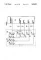
- FIG. 4is a block diagram of the ECG monitoring unit
- FIG. 5is a block diagram of the ECG analog signal conditioning circuit
- FIG. 6is a block diagram of the pacemaker pacing spike detector
- FIG. 7is a simplified logic flow diagram of the ECG analysis
- FIG. 8is a circuit diagram of the ECG optical interface
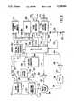
- FIG. 9is a block diagram of the blood pressure monitoring unit
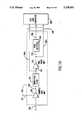
- FIG. 10is a block diagram of the K sound signal conditioning circuit
- FIG. 11is a simplified logic flow diagram for the blood pressure monitoring unit.
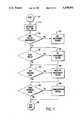
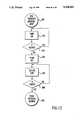
- FIG. 12is a simplified logic flow diagram of the rapid blood pressure measurement method.
- ambulatory patient monitoring system 100for measuring and storing predetermined diagnostic parameters of a patient.
- ambulatory monitoring system 100is directed to the concept of providing simultaneous ambulatory measurements of multiple diagnostic parameters, such as the electrocardiogram, blood pressure, oxygen saturation, temperature, and respiratory function, while still maintaining the capability of utilizing the measuring devices for each of the diagnostic parameters independently, on different individual patients.
- system 100is particularly adapted to provide event triggered blood pressure measurements, the programmed blood pressure measurement protocol being interrupted in response to the detection of a particular ECG abnormality identified by the ECG monitoring unit 110.
- the blood pressure monitoring unit 210is further enhanced through the use of an R-wave gating signal, for use in the auscultatory method of blood pressure measurement transmitted from the ECG unit 110 to the blood pressure monitoring unit 210, the blood pressure unit 210 using the gating signal to establish a window for detecting of Korotkoff sounds (K sounds), thereby reducing the likelihood of detecting transient noise, motion artifacts, or the like as valid K sounds.
- unit 210is capable of measuring blood pressure in an oscillometric mode, using pressure pulsations in the cuff to establish the systolic and diastolic levels.
- the oscillometric methodcan be carried out substantially simultaneously, with both sets of measurements stored for subsequent comparison, however, there is currently no clinical need for both sets of data. Therefore, unit 210 switches to the oscillometric method when K sounds cannot be detected, acting as a fail safe. If the cuff pressure drops below a predetermined value and K sounds have not yet been detected, the cuff is reinflated and the deflation process repeated using the oscillometric method.
- Ambulatory monitoring system 100is modular in construction to provide at least three monitoring systems in one, and having the capacity to greatly exceed that number.
- the portable portion 102 of system 100provides for the simultaneous and coordinated measurement of both ECG and blood pressure parameters, functioning as a single instrument.
- each of the monitoring units 110, 210may be used individually, each unit being useable on a different patient.
- system 100can be configured as three different instruments, two of which being operable simultaneously.
- the ECG monitoring unit 110functions as the master unit, with the blood pressure unit 210 defining a slave unit.
- the blood pressure unitis responsive to predetermined events identified by the master ECG monitoring unit 110 for initiating a blood pressure measurement.
- system 100may incorporate other modular ambulatory monitoring units for use with either or both of the ECG and blood pressure units, such as for monitoring oxygen saturation, temperature, electroencephalograph signals, one or more respiratory functions, and myoelectric potentials from particular portions of the patient's body.
- each of these modulesmay be utilized independently, or placed in various combinations to form a monitoring instrument tailored to suit the diagnostic requirements for a particular patient.
- an oxygen saturation measuring modulecould be used in combination with both units 110 and 210, or used with either one, alone.
- Such an oxygen saturation measurement modulecould function as a master unit, triggering blood pressure measurements, or as a slave, being triggered by the ECG unit 110.
- system 100may include a telemetric module, for transmitting data measurements, either in real time, or downloaded from a respective module's memory, for transmission to a remote receiver through an optical or radiofrequency data link.
- FIG. 1there is shown the portable portion 102 of ambulatory monitoring system 100 as might be worn by a patient.
- the ECG monitoring unit 110 and the blood pressure monitoring unit 210are disposed in side-by-side relationship within a carrying pouch 104, and releasably secured to the patient by means of a belt or strap 106.
- the exact form or means for releasably securing the portable portion 102 of system 100is not important to the inventive concept, and may be accomplished by any of a number of harness or strap arrangements, well known in the art. It should be noted that units 110 and 210 need not be disposed in abutting relationship, as it is only necessary that their respective optical communication interfaces be aligned, one with respect to the other.
- a plurality of ECG electrodes 114are par of an ECG electrode assembly 109, coupled to the ECG monitoring unit 110.
- Electrode assembly 109further includes a reference electrode 115 coupled to a lead 113.
- ECG electrodes 114 and 115may be any of a wide variety of disposable or reusable electrodes, well known in the art.
- the blood pressure monitoring unit 210includes an inflatable cuff 204 which carries an audio transducer 206, positioned adjacent the patient's arm, for converting the K sounds to electrical signals transmitted to monitoring unit 210 through an electrical cable 208.
- the cuff 204is inflated and deflated through a hose 202 coupled to a fluid pump or compressed fluid supply and a bleed valve.
- the transducer cable 208may be integrated into the hose 202, wherein cable 208 is coupled to an exterior surface of hose 202, extends through the fluid carrying lumen, or through a separate lumen formed therein.
- a personal-type computer 120is coupled to respective diagnostic parameter measuring units 110, 210, by means of optically isolated serial data links 124, 224.
- Bidirectional communication between the monitoring units 110, 210 and the personal-type computer 120is provided through respective serial interfaces 48, 252 (shown in FIGS. 4 and 9) which are coupled to respective serial ports of computer 120 through respective connectors 118, 218 and serial data cables 124, 224.
- the physicianutilizes the personal-type computer 120 to enter particular patient information, which is relevant to identifying that patient and the data collected therefrom, as well as enter particular measurement protocols, operating parameters, and event triggering data, to be more fully described in following paragraphs.
- the computer 120allows the physician to program particular functions of the monitoring units 110, 210 for tailoring the diagnostic measurements to a particular patient.
- the computer 120further serves as a means for retrieving data from the respective monitoring units 110, 210.
- Each of units 110, 210are provided with sufficient memory for storing the diagnostic parameters measured over at least a twenty-four hour period.
- all of the measurement data stored within a respective measuring unit 110, 210can be downloaded to the main memory and mass storage systems of computer 120 through the serial data connections selectively established therebetween.
- the measurement datacan be transmitted to computer 120 in real time, as the measurements are being taken. In this real time data mode, the measurements can be displayed on the computer's monitor, that is, both the ECG waveforms, heart rate and blood pressure measurements can simultaneously be displayed.
- Computer 120includes a digital to analog converter coupled to a speaker 136 through an audio cable 134, for playing back the K sounds while the cuff pressure measurements are displayed on the computer's monitor.
- the physiciancan display for any time period, the ECG waveform, the heart rate, as well as display the number and time of day of the occurrence of abnormal conditions.
- abnormal conditionsas arrhythmias, absence of particular ECG waveform components, and pacemaker malfunctions are separately identified and classified.
- Arrhythmiasare further identified and classified as to type, such as ventricular tachycardia, paroxysmal supraventricular tachycardia, bradycardia, dropped beats or pauses, couplets, runs, for example.
- ECG monitoring unitidentifies these abnormal conditions as they occur, and can be programmed to trigger a concurrent blood pressure measurement concurrently therewith.
- FIG. 3there is shown an advantage of the optical interface 50, 254 for units 110, 210, respectively, in combination with the real time mode of the units.
- the patientmay be provided with a modem 130 and an optical interface unit 122, coupled to modem 130 by means of a serial data cable 128 for communicating with the ECG monitoring unit 110.
- ECG unit 110is being described with respect to FIG. 3 for exemplary purposes, it should be understood that blood pressure monitoring unit 210, or any other module of system 100, can be substituted interchangeably for unit 110, as this portion of the system operation applies equally to any of the monitoring units.
- Optical interface unit 122includes an optically transmissive window 126, which complements the window 116 of the monitoring unit 110, and is provided with similar circuitry to permit optically isolated communication through the telephone line 132, to the physician's personal-type computer 120, or some other computer system or digital equipment. In this fashion the physician can monitor the patient's ECG waveform remotely, or alternately download the data stored within the memory of the ECG monitoring unit 110 for monitoring the data previously obtained.
- the ECG electrode cable 108carries signals from two pairs of electrodes 114, defining two ECG channels.
- the leads representing these two ECG channelsare carried by the cable 108 and are coupled to an impedance switching network 10.
- Impedance switching networkdefines a digitally controlled switch capable of injecting a small test current back through the leads to the patient. This test current establishes a voltage across a respective pair of leads which is used to measure the impedance across the electrodes, thereby allowing the physician to insure proper electrode coupling with the patient.
- the impedance checking function carried out through the switch network 10is controlled through the coupling line 11 which couples switch network 10 to microprocessor 30.
- the ECG signal amplification circuits, analog-to-digital converter, and microprocessorare utilized in this impedance measurement.
- the electrical signals conducted from the electrodes of the respective channelseither the substantially constant voltage of the impedance measurement or the ECG waveform signals, are coupled to respective signal conditioning circuits 12, 18 by means of respective coupling lines 7, 9.
- the signal conditioning circuit 12comprises a fixed gain amplifier 300 having an input coupled to the coupling line 7, and an output coupled to a high pass filter circuit 302.
- High pass filter circuit 302has a lower cut-off frequency approximating 0.05 hertz, and may be constructed as either an active or passive filter circuit, however, an active filter circuit is preferred.
- the output of high pass filter 302is coupled to the input of a variable gain amplifier stage 304.
- Variable gain amplifier stage 304is digitally programmable, having a gain control digital line 13 coupled to microprocessor 30.
- the variable gain of amplifier 304 stagemay be adjustable within a range of 0.5-21, and preferably within a range of 3 to 12.5.
- Variable gain amplifier stage 304may further include a fixed gain amplifier in combination therewith.
- the output of variable gain amplifying stage 304is coupled to a low pass filter 306, having a frequency cut-off of approximately 40 hertz.
- variable gain amplifier stage 304The gain of variable gain amplifier stage 304 is adjusted by microprocessor 30 by sampling the ECG signals with the gain set at a minimum value. If the peak amplitude of the detected R-wave is less than a predetermined value, the gain is increased by an incremental value. If at this increased gain step the R-wave amplitude is less than a second predetermined value, the gain is advanced another step, otherwise it will remain. Although three incremental levels of gain have proved satisfactory, obviously, more or less increments of gain could be employed without departing from the spirit and scope of the invention.
- the variable gain portion of the signal conditioning circuit 18is controlled through a digital line 15 coupled to microprocessor 30, as shown in FIG. 1, to provide independent and variable gain for that respective channel.
- the output 14, 20 of each of the signal conditioning circuits 12 and 18are respectively coupled to an analog-to-digital multiplexing converter 16 by means of the respective coupling lines 14 and 20.
- the output of a battery monitoring circuit 17is coupled to one input of the multiplexing A-to-D converter 16 for providing battery condition data to microprocessor 30.
- microprocessor 30When microprocessor 30 detects the low battery signal, it stores the alarm condition and the time of day that it occurred, which is recovered when the physician down loads the memory. An alarm indication could be triggered in response to a low battery condition to alert the patient, but the consequences of not doing so is simply to repeat the test, and therefore provides little justification for inclusion of the feature.
- Multiplexing A-to-D converter 16sequentially converts the analog signals on each of the input lines to a multi-bit digital representation thereof, for communication to microprocessor 30 through the coupled line 26.
- One multiplexing analog-to-digital converter successfully utilized in system 100is a 12-bit device having the designation TLC1540, manufactured by Texas Instruments, Inc. of Dallas, Tex.
- the ECG monitoring unit 110includes a pacemaker spike detector circuit 24 having an input coupled to the output line 20 of the channel 2 signal conditioning circuit 18.
- the pacemaker spike detector circuit 24includes a high pass filter circuit 308 having an input coupled to line 22.
- High pass filter 308is provided with a frequency cutoff at 20 Hertz to remove the ECG signal and any muscle artifacts which might be present in the signal.
- the output of high pass filter 308is coupled to an absolute value amplifier 310.
- An absolute value amplifieris utilized because the pacemaker spike may be either a positive or negative going pulse, which otherwise would require separate amplification and detection stages, the outputs of which would then have to be combined.
- Absolute amplifier 310has a gain value approximating 500 for amplifying the pacemaker spike signal to a magnitude within the range of 10 through 500 millivolts.
- the output of absolute value amplifier 310is coupled top the input of a peak detector 312.
- Peak detector 312establishes a threshold value which must be exceeded for a digital logic level signal to be output on line 25 for coupling with microprocessor 30.
- Peak detector 312is a conventional comparator-type circuit arrangement, well known in the art, with a threshold value approximating 15 millivolts.
- the pulse provided to microprocessor 30 through coupling line 25is subsequently analyzed to determine if the signal provided on line 25 is in fact a signal representing the pacemaker spike.
- a pacer signal from a pacemakerhas a fixed pulse width, typically in a range between 0.5 and 2.0 milliseconds, the microprocessor 30 therefore disregards any signal supplied by pacemaker spike detector circuit 24 which is outside that range. Thus, data may be accumulated on the operation of a patient's pacemaker. This feature is particularly advantageous for a patient having the type of pacemaker with a packing rate which is variable responsive to the patient's activity level.
- Microprocessor 30is a multipurpose processing device which performs communication and analytical functions of monitoring unit 110.
- microprocessor 30is a commercially available 16-bit single chip microprocessor having a designation 68332, available from Motorola Semiconductor, Inc. of Phoenix, Ariz.
- the ECG data supplied through line 26 from the analog-to-digital converter 16is monitored to determine whether the gain is properly set in the respective signal conditioning circuits 12 and 18, the microprocessor outputting control signals on respective control lines 13, 15 for selecting the appropriate gain values for input to the signal conditioning circuits 12, 18.
- Microprocessor 30further performs real-time analysis of the ECG data, which along with the raw ECG data is processed through a data compression algorithm, and stored in the electrically erasable, electrically programmable read-only memory 46.
- Memory 46is constructed from commercially available memory devices known as Flash memory devices, having a manufacturer's designation 28F020, available from Intel Corporation of Santa Clara, Calif.
- Data storage memory 46provides 4 megabytes of non-volatile memory for storage of the ECG and analysis data within monitoring unit 110.
- the digitized data representing the ECG signal from either one of the two input channels (each of the channels being processed alternately)is provided from the input block 150 to the smoothing filter block 152.
- the smoothing filter step represented by block 152utilizes well known techniques for enhancing the signal, with respect to noise.
- the smoothed datais supplied to the data compression block 166, wherein a data bit reduction procedure is carried out.
- the compressed data from block 166is provided to the storage output block 168, providing the data for storage within the data storage memory 46, followed by the step of reducing the frequency of clock circuit 32, in block 167. The importance of changing the clock frequency will be described in following paragraphs.
- the filtered data from block 152is also supplied to the beat detection decision block 154.
- the datais transmitted from decision block 154 to the beat classification block 156 and the heart rate computation block 164.
- the heart rate computed in block 164is transmitted to data compression block 166 for subsequent storage in the data storage memory 46.
- Classification block 156identifies arrhythmias from the beat timing supplied from the beat detection block 165, classifying the beat into predetermined categories.
- the arrhythmia type identified by the beat classification block 156is transmitted to the data compression block 166 for storage in the data storage memory 46. Additionally, the arrythmia type is transmitted to the rhythm classification block 162 so as to further distinguish reoccurring events from those of a transient nature.
- rhythm classification block 162is similarly transmitted to the data compression block 166 for storage in data storage memory 46.
- the output of the beat classification block 162is also supplied to the blood pressure trigger detection decision block 158, and if the type of arrhythmia or rhythm identified by block 162 matches that which has been predetermined to require a simultaneous blood pressure measurement, previously entered by the physician, than the signal transmission output block 160 is enabled, for sending a trigger control signal to the blood pressure unit through the optical data link, as has previously been described.
- microprocessor 30is coupled to a clock circuit 32, which may be provided internal to microprocessor 30 or as an ancillary device.
- Clock circuit 32provides the basic clock impulses, whose frequency determined the operational speed at which microprocessor 30 operates.
- the clock signals output from clock circuit 32are supplied to microprocessor 30 through coupling line 34, as is conventionally found in microprocessor systems.
- microprocessor 30includes an output line 32 coupled to clock circuit 32 for controlling the clock frequency supplied therefrom.
- the clock speed control output 32is utilized to adapt the clock circuit frequency to the function being performed by the microprocessor.
- the frequency of clock 32is increased to support the real time processing of the ECG data. It should be understood that the frequency reduction step of block 169 is not reached until all of the data, raw and analysis, has been stored.
- the clock circuitis operated at its highest frequency, 8 megahertz for example, and during periods, between heartbeat signals, the clock frequency may be reduced down to its lowest operating frequency, such as 32 kilohertz, or some frequency in between those limits, as a function of the type of processing which is to be performed.
- Use of this adaptable clock frequencysaves considerable power in ECG monitoring system 110. This power saving feature is critical importance for a portable system operating from a battery power supply, which must function continuously and reliably for over a 24-hour period. Minimization of power supply size substantially contributes to minimization of unit 110, which provides particular advantages for a device that must be worn by a patient for extended periods of time.
- microprocessor 30provides output data which is stored in the programmable read-only memory 46, through the data bus 38 with appropriate addressing supplied through the address bus 37.
- Microprocessor 30is further supported by 128-kilobytes of random access memory 42 as temporary storage for use in the data compression and arrhythmia analysis processing.
- the operations of microprocessor 30are controlled by a program stored in program memory 44, coupled to the data bus 38 and address bus 37.
- Program memory 44is a 256-kilobit read-only type memory.
- Read-only type memory 44may be constructed of the Flash type memory devices, similar to those utilized in memory 46, thereby allowing field upgrades of the control program software ECG monitoring unit 110 utilizing the electrical erasure and programming functions of the device.
- each of the memory subsystems 42, 44 and 46are each coupled to data bus 38 and address bus 37.
- a general I/O interface 36which is selected by means of the I/O port selection control line 39, coupled to microprocessor 30.
- the input to general interface 36is coupled to a momentary push-button switch 35 for coupling a reference potential thereto.
- Switch 35functions as an event switch, which functions as an event marker for the ECG signal.
- General interface 36may comprise a commercially available 74HCT540 tri-state buffer line driver, available from Motorola Semiconductor Products, Inc. of Phoenix, Ariz.
- ECG monitoring unit 110includes a serial interface connector 118 for coupling with an external computing device.
- Connector 118is coupled to serial interface 48 by means of a respective serial input and output line, the serial interface being coupled in turn with microprocessor 30 by means of respective input and output lines 43 and 45.
- Serial interface 48may be incorporated into microprocessor 30, or constructed from any one of a plurality of commercially available serial interface circuits for coupling with microprocessor 30.
- the optical interface 50is coupled to microprocessor 30 by means of respective input and output lines 40 and 41.
- the optical interface 50converts electrical signals transmitted from microprocessor 30 into optical signals, preferably within the infrared bandwith of the electromagnetic spectrum, which are transmitted through the tranmsissive window 116 to a slave module, such as the blood pressure measuring unit 210.
- Optical signals from the slave modulepass through transmissive window 116 and are received by an optical detector, such as a phototransistor, for conversion to electrical signals which are transmitted to microprocessor 30 by line 40.
- Optical interface 50includes three light emitting diodes 70, 72 and 74, each coupled in series with a respective current-limiting resistor 76, 78 and 80. Each of resistors 76, 78 and 80 being coupled to a common power supply terminal 82 for receiving the positive power supply voltage thereon. The opposing end of light emitting diodes 70, 72 and 74 being coupled to the output of a respective tri-state buffer amplifier 84, 86 and 88.
- the use of tri-state buffers for driving the light emitting diodes 70, 72 and 74is another power-saving feature incorporated into ECG monitoring unit 110.
- the light emitting diodesare turned off when the interface is disabled, by means of the interface enable control line 92 coupling microprocessor 30 to each of the tri-state control inputs 83, 85 and 87 of the respective tri-state amplifiers 84, 86 and 88 coupled to light emitting diodes 70, 72 and 74.
- the drivesare placed in the high impedance mode, disabling the interface, no power is consumed by the light emitting diodes. This would otherwise not be the case, since the state of some of the peripheral lines, such as the clock line 98 cannot be controlled and thus, would otherwise permit the light emitting diodes to consume power.
- each of the drivers 84, 86 and 88is enabled, turning light emitting diode 70 on, allowing transmission of serial data from line 96 through the light emitting diode 72, and transmission of the serial clock from line 98 through light emitting diode 74.
- Serial datais received from the slave module, such as the blood pressure monitoring unit 210, through the phototransistor 73.
- Phosotransistor 73is coupled in series with a load resistor 75, which is in turn coupled to the positive power supply input terminal 82.
- the emitter of the phototransistor 73is coupled to the ground reference potential for the system.
- the output of phototransistor 73, taken from the collector thereof,is coupled directly to microprocessor 30 on interrupt line 95.
- interrupt line 95alerts the microprocessor to the transmission of data from the slave module, in order to interrupt its current processing operation and direct appropriate resources to the receipt of the incoming data.
- the output of phototransistor 73is coupled to the input of the tri-state buffer amplifier 90 for transmission through the serial input line 94 to microprocessor 30.
- amplifier 90includes a tri-state control input 91 which is coupled to the interface enable control line 92.
- Microprocessor 30responds by changing the logic level of the interface enable line 92 form a high to a low, illuminating light emitting diode 70 to indicate to the slave module that microprocessor 30 is ready to receive data, the data being synchronized with the serial clock signal of microprocessor 30, transmitted by light emitting diode 74.
- output lines 92, 96 and 98are represented by coupling line 41
- input lines 94 and 95are represented by coupling line 40.
- Each of units 110 and 210are capable of using their respective optical interface to automatically detect the presence of the other respective unit.
- unit 110When unit 110, for instance, is turned on and completes initial self test and calibration functions, a signal is transmitted by the optical interface 50. If after a predetermined delay no response is received, ECG unit 110 operates as an independent unit, unless an interrupt signal is received on line 95 at some later time. In this manner ECG unit 110 can save power, by not transmitting an R-wave gating signal for every beat.
- the blood pressure unit 210is capable of detecting the presence of the ECG unit, for determining whether it is to function as an independent unit. However, the operational mode of unit 210 could be set at the time the measurement protocol is programmed by the physician.
- a transducer assembly 214includes an audio transducer 206, which may be a microphone, for converting the K sounds into electrical signals transmitted by electrical cable 208 to signal conditioning circuit 270, which performs amplification and filtering functions, to be described in following paragraphs.
- the output of signal conditioning circuit 270is coupled to analog-to-digital multiplexing converter 266 through coupling line 268.
- Coupling line 268represents the output of several signals from signal conditioning circuit 270, to be more fully described in following paragraphs.
- the digitized output of the analog-to-digital multiplexing converter 266is supplied to microprocessor 262 through coupling line 264.
- Microprocessor 262provides a control signal to signal conditioning circuit 270 by means of coupling line 271 for controlling the amplification gain thereof.
- the transducer or sensor assembly 214further includes a pressure transducer 212 for measuring the inflation pressure of cuff 204 through hose 202.
- the electrical output of pressure transducer 212is coupled to amplifier 274 through coupling line 232.
- the output of amplifier 274is coupled to analog-to-digital multiplexing converter 266 through coupling line 272.
- blood pressure monitoring unit 210includes a battery monitoring circuit 248 having an output coupled to an analog-to-digital multiplexing converter 266 through coupling line 249.
- Microprocessor 262stores the alarm condition and time of day it occurred with the blood pressure data.
- Analog-to-digital multiplexing converteris a commercially available device, like that utilized in monitoring unit 110, previously described.
- Microprocessor 262may be an 8-bit microprocessor having internal serial interface circuitry.
- One such microprocessor which has been successfully utilized in this applicationhas an identification number of 68HC811, from Motorola Semiconductor Products, Inc. of Phoenix, Ariz.
- Microprocessor 262outputs a pump control signal on line 240 which is coupled to a driver amplifier 242.
- the output of the driver amplifier 242is coupled to the pump 244 by means of the coupling line 243.
- Pump 244pumps fluid through an output conduit 246 through bleed valve 246 and conduit 236 to pressure transducer 212, for coupling with cuff 204 through hose 202.
- the fluid utilizedis air, although other fluids may be substituted.
- pump 244may be replaced by an electrically actuated valve coupled to a supply of compressed fluid, which may be utilized to inflate cuff 204.
- Transducer assembly 214is utilized during the inflation step of the blood pressure measurement to determine when the patient's brachial artery has been occluded by the cuff, the pressure being over a predetermined value and there being an absence of K sounds.
- pump 244is shut down, by the change in state of the control signal output on line 240.
- a control signalis output on line 261 which is supplied to driver amplifier 260.
- Driver amplifier 260provides an output on line 247 for controlling the bleed valve 246, which controls the release of fluid from cuff 204 through hose 202 on conduit 236.
- the rate at which fluid pressure is bled from the cuff 204is controlled by the outlet orifice of bleed valve 246, with the increments of pressure at which the microprocessor checks for the presence of K sounds being controlled by the length of time that the bleed valve is opened, that length of time being the time between beats.
- the cuff pressurewould decrease approximately 1.3 mm of Hg.
- the microprocessorwould check for detection of a K sound, and then proceed to open the bleed valve for the next interval between beats. Each incremental pressure value is stored in memory during the measurement procedure.
- the microprocessoronly looks at the output of peak detector 336 a predetermined delay time after the R-wave signal. The pressure at which the K sounds cease to be detected establishes the diastolic pressure.
- band pass filter 324may be an active filter circuit having a center frequency approximating 23 hertz, low frequency cutoff approximating 11.5 hertz and an upper frequency cutoff approximating 34.5 hertz.
- the output of band pass filter 324is coupled to one channel of analog-to-digital multiplexing converter 266 through coupling line 328, providing the K sound audio signals to microprocessor 262 for storage and subsequent analysis.
- the provision for storing actual K soundsis a critically important new feature for ambulatory blood pressure monitoring units.
- the physicianmanually takes a patient's blood pressure while the patient is at rest, comparing the manual measurement with the ambulatory unit's measurement.
- the physiciancan listen to the K sounds and observe the cuff pressure reading to establish his own blood pressure measurement, for comparison with which was determined by the measurement algorithm.
- the stored K soundscan be input to more sophisticated analysis systems for further analysis.
- the stored K soundsfacilitate the development of new blood pressure measurement algorithms, providing an easy method for evaluating their accuracy over a wide range of patient activity.
- band pass filter 324is supplied to absolute value amplifier 330 through coupling line 246.
- Absolute value amplifier 330converts the bipolar audio signal output from filter 324 into a unipolar signal and outputs a signal representing the envelope thereof.
- the K sound envelopeis coupled to a respective channel of analog-to-digital multiplexing converter 266 through coupling line 334.
- the output of absolute value amplifier 330is also coupled to peak detector 336 by means of coupling line 3332. Peak detector 336 provides a pulse output responsive to the K sound envelope signal exceeding a predetermined threshold, thereby providing a pulse indicating detection of a K sound.
- the output of peak detector 336is coupled to yet another channel of analog-to-digital multiplexing converter 266 by means of coupling line 338.
- Each of the signal lines 328, 334 and 338are represented by the signal line 268 in the block diagram of FIG. 9.
- a real time interrupt generator 276coupled to microprocessor 262 by means of the coupling line 277.
- Real time interrupt generator 276forms part of a power saving subsystem of blood pressure monitoring unit 210.
- Blood pressure monitoring unit 210is periodically put in a "sleep" mode wherein the microprocessor operation is stopped and the current draw is dropped to the microamp level, providing a substantial power savings.
- the microprocessoris "awakened” to perform housekeeping chores, such as incrementing counters and checking status of communication ports, and taking blood pressure measurements, as required.
- a reset of microprocessor 262is initiated at block 172.
- the signal from real time interrupt generator 276is a repetitive clock signal defining a predetermined increment of time, for example, 0.5 seconds.
- the time of day counteris incremented in block 174.
- the incremented counter of block 174provides a time of day which is compared in block 176 with a selected measurement protocol to determine if it is time for a blood pressure measurement to be taken.
- the microprocessor's activityis controlled by the blood pressure measurement routine indicated by block 178.
- the measurement protocolwhich can be programmed by the physician is quite versatile. In additional to setting a repetition rate for the measurements, the rate can be varied at different portions of the day. For instance, blood pressure measurements may be scheduled to be taken every 10 minutes from 7:00 to 9:00 A.M., every 30 minutes from 9:00 A.M. to 7:00 P.M., and every 60 minutes from 7:01 P.M. to 6:59 A.M.
- the microprocessortests, in block 180, whether the event switch has been operated. If the event switch has been operated then the microprocessor proceeds to perform a blood pressure measurement as indicated in block 182. If the event switch has not been operated, or subsequent to the blood pressure measurement having been made, the microprocessor checks the optical interface to determine if the ECG unit 110 is signalling that a blood pressure measurement should be taken, so as to correspond to the occurrence of some predetermine abnormality in the ECG signal. If such an event has occurred, then, as indicated in block 186, the microprocessor performs a rapid blood pressure measurement, as will be more fully described in following paragraphs.
- the microprocessorlooks to the serial interface 252 to determine if it is active, as indicated in block 188. If the result of this test is True, then the microprocessor performs the necessary communications operations, as indicated in block 190. If the test of block 188 is Not True, or such communications is completed, the microprocessor is then put in a stop mode, as indicated by block 192, wherein its functions cease and power consumption is substantially reduced.
- This power saving featureis of critical importance to the design of monitoring unit 210, permitting continuous operation for greater than 24 hours with a smaller size battery power supply than would otherwise be required. Such facilitates unit 210 being constructed as a small compact unit, which is particularly advantageous for a device which must be worn by a patient for extended periods of time.
- the event switch 235is a momentary push-button switch coupled in series with a load resistor 231 between the positive power supply voltage, on one end of resistor 231, and the power supply reference coupled to the opposing terminal of switch 235. Coupled to the node between switch 235 and load resistor 231 there is provided an input line 233 coupled to an input terminal of microprocessor 262. By this arrangement, line 233 is held at a high logic level when switch 235 is open, and brought to a low logic level when the contacts of switch 235 are closed.
- an optical signal transmitted from light emitting diode 74 of optical interface 50, through light transmissive window 216 of blood pressure monitoring unit 210is received by a respective phototransistor for transmission of the clock signal to microprocessor 262 through line 259.
- the received clock signalbeing utilized for synchronization of the serial transmission sent to ECG monitoring unit 110 and the transmission received therefrom.
- the serial data transmitted from light emitting diode 72 of optical interface 50is received by a respective phototransistor within optical interface 254 and transmitted to the serial input of microprocessor 262 through line 257.
- the serial data transmitted from microprocessor 262is transmitted to optical interface 254 by line 255, wherein a light emitting diode is driven to provide an optical output transmitted through transmissive window 216 to ECG monitoring unit 110 for receipt by phototransistor 73.
- a serial interface 252is provided for communication with such devices as the personal type computer 120 shown in FIG. 1.
- the serial interface connected 218provides the means for coupling serial input and output lines, through serial interface 252, to respective serial input and output ports of microprocessor 262.
- Serial data from microprocessor 262is carried by line 253 to serial interface 252, and serial data therefrom is transmitted to microprocessor 262 by line 241.
- programmable read-only memory 256is an electrically erasable programmable read-only memory for providing non-volatile storage of the blood pressure measurement data. Additionally, the software required to operate microprocessor 262 is stored within programmable read-only memory 256, along with the selected measurement protocol entered by the physician through the personal type computer 120. Subsequently, the data is read from memory 256 and transmitted through serial interface 252 for display, and possible subsequent processing by personal computer 120. Electrically erasable read-only memory 256 is formed by Flash memory devices, similar to those utilized in the ECG monitoring unit 110.
- Flash memory devicehas the part number designation 28F020, available from Intel Corporation of Santa Clara, Calif.
- Programmable ROM memory 256is coupled to microprocessor 262 through the bi-directional data bus 250 and address bus 251. Further, microprocessor 262 is coupled to 128 kilobit random access memory 258 by means of bi-directional address bus 250 and address bus 251. Random access memory 258 provides short-term storage for data processing and a unique program storage function, to be further described in following paragraphs.
- Blood pressure monitoring unit 210is provided in a very compact form, utilizing a minimum number of components, minimizing power consumption, and maximizing efficiency of those components utilized.
- storage densityis maximized, as data may be stored beginning with those memory locations immediately following those utilized for program storage. If subsequent software upgrades enlarge the size of the program storage requirements, the data storage is just simply started at a higher address location. As long as the total remaining programmable read-only memory is sufficient for a 24-hour period of data accumulation, the overall system performance will not be affected.
- the operating program for microprocessor 262Prior to erasure of programmable read-only memory 256, the operating program for microprocessor 262 is transferred from read-only memory 256 to random access memory 258. Subsequent to the transfer of the operating program, programmable read-only memory 256 is erased, to permit use on a new patient, or to gather another 24-hour accumulation of data on the same patient. While the operating program is stored in random access memory 258 such can be modified with new measurement protocols entered by the physician through serial interface 252. Additionally, if the operating program is to be replaced, such replacement may be entered through interface 252 for storage in programmable read-only memory 256, subsequent to erasure thereof.
- FIG. 12there is shown a flow diagram for the rapid blood pressure measurement selected to be utilized by the physician, responsive to particular transient abnormal conditions identified by the ECG monitoring system 110.
- the pump 244Responsive to the ECG monitoring unit triggering a blood pressure measurement at entry block 240, the pump 244 is turned on, as indicated in block 342.
- microprocessor 262tests to see if K sounds are present, as indicated in block 344. If K sounds are present, such indicates that the brachial artery is not occluded, and the inflation provided by the energization of pump 244 continues until K sounds are not longer detected.
- pump 244When K sounds are no longer detected, pump 244 is turned off, as indicated in block 346. Immediately thereafter, the bleed valve 246 is deflated in predetermined, relatively large steps, in the approximating range of 5.0-10.0 millimeters of Hg, indicated in block 348. At each incremental drop in cuff pressure, microprocessor 262 tests to determine if any K sounds are present, as indicated in block 350. If no K sounds are found, the cuff 204 is deflated another increment, this process continuing until K sounds are detected. When K sounds are detected the pressure reading, as indicated by an output from the pressure transducer 212, is stored in memory, as indicated in block 352.
- a clinically significant measurementis provided for determining whether a hypotensive condition has coincided with a transient condition of electrocardioactivity. If this approximation of systolic pressure was below a predetermined minimum value, as a result of the arrhythmia, a diastolic measurement would not be indicated in the data.
Landscapes
- Health & Medical Sciences (AREA)
- Life Sciences & Earth Sciences (AREA)
- Cardiology (AREA)
- Engineering & Computer Science (AREA)
- Physics & Mathematics (AREA)
- General Health & Medical Sciences (AREA)
- Heart & Thoracic Surgery (AREA)
- Medical Informatics (AREA)
- Molecular Biology (AREA)
- Surgery (AREA)
- Animal Behavior & Ethology (AREA)
- Public Health (AREA)
- Veterinary Medicine (AREA)
- Biomedical Technology (AREA)
- Vascular Medicine (AREA)
- Pathology (AREA)
- Biophysics (AREA)
- Physiology (AREA)
- Ophthalmology & Optometry (AREA)
- Acoustics & Sound (AREA)
- Hematology (AREA)
- Microelectronics & Electronic Packaging (AREA)
- Pulmonology (AREA)
- Measuring And Recording Apparatus For Diagnosis (AREA)
- Measuring Pulse, Heart Rate, Blood Pressure Or Blood Flow (AREA)
- Measurement And Recording Of Electrical Phenomena And Electrical Characteristics Of The Living Body (AREA)
Abstract
Description
Claims (24)
Priority Applications (11)
| Application Number | Priority Date | Filing Date | Title |
|---|---|---|---|
| US07/790,500US5238001A (en) | 1991-11-12 | 1991-11-12 | Ambulatory patient monitoring system having multiple monitoring units and optical communications therebetween |
| CA002078101ACA2078101A1 (en) | 1991-11-12 | 1992-09-11 | Ambulatory patient monitoring system |
| EP92308528AEP0542413B1 (en) | 1991-11-12 | 1992-09-18 | Ambulatory patient monitoring systems |
| DE69211494TDE69211494T2 (en) | 1991-11-12 | 1992-09-18 | Portable patient monitoring device |
| AT92308528TATE139095T1 (en) | 1991-11-12 | 1992-09-18 | PORTABLE PATIENT MONITORING DEVICE |
| JP31268192AJP3367121B2 (en) | 1991-11-12 | 1992-10-29 | Walking monitor system for patients |
| MX9206340AMX9206340A (en) | 1991-11-12 | 1992-11-04 | AMBULATORY SYSTEM FOR PATIENT SUPERVISION. |
| KR1019920021120AKR930009571A (en) | 1991-11-12 | 1992-11-11 | Gait Patient Monitor System |
| US08/064,454US5309920A (en) | 1991-11-12 | 1993-05-21 | Ambulatory electrocardiographic patient monitoring system and method therefor |
| US08/064,928US5322069A (en) | 1991-11-12 | 1993-05-24 | Ambulatory ECG triggered blood pressure monitoring system and method therefor |
| US08/262,925US5568814A (en) | 1991-11-12 | 1994-06-20 | Ambulatory patient monitoring system |
Applications Claiming Priority (1)
| Application Number | Priority Date | Filing Date | Title |
|---|---|---|---|
| US07/790,500US5238001A (en) | 1991-11-12 | 1991-11-12 | Ambulatory patient monitoring system having multiple monitoring units and optical communications therebetween |
Related Child Applications (2)
| Application Number | Title | Priority Date | Filing Date |
|---|---|---|---|
| US08/064,928DivisionUS5322069A (en) | 1991-11-12 | 1993-05-24 | Ambulatory ECG triggered blood pressure monitoring system and method therefor |
| US08/262,925ContinuationUS5568814A (en) | 1991-11-12 | 1994-06-20 | Ambulatory patient monitoring system |
Publications (1)
| Publication Number | Publication Date |
|---|---|
| US5238001Atrue US5238001A (en) | 1993-08-24 |
Family
ID=25150868
Family Applications (4)
| Application Number | Title | Priority Date | Filing Date |
|---|---|---|---|
| US07/790,500Expired - Fee RelatedUS5238001A (en) | 1991-11-12 | 1991-11-12 | Ambulatory patient monitoring system having multiple monitoring units and optical communications therebetween |
| US08/064,454Expired - Fee RelatedUS5309920A (en) | 1991-11-12 | 1993-05-21 | Ambulatory electrocardiographic patient monitoring system and method therefor |
| US08/064,928Expired - Fee RelatedUS5322069A (en) | 1991-11-12 | 1993-05-24 | Ambulatory ECG triggered blood pressure monitoring system and method therefor |
| US08/262,925Expired - LifetimeUS5568814A (en) | 1991-11-12 | 1994-06-20 | Ambulatory patient monitoring system |
Family Applications After (3)
| Application Number | Title | Priority Date | Filing Date |
|---|---|---|---|
| US08/064,454Expired - Fee RelatedUS5309920A (en) | 1991-11-12 | 1993-05-21 | Ambulatory electrocardiographic patient monitoring system and method therefor |
| US08/064,928Expired - Fee RelatedUS5322069A (en) | 1991-11-12 | 1993-05-24 | Ambulatory ECG triggered blood pressure monitoring system and method therefor |
| US08/262,925Expired - LifetimeUS5568814A (en) | 1991-11-12 | 1994-06-20 | Ambulatory patient monitoring system |
Country Status (8)
| Country | Link |
|---|---|
| US (4) | US5238001A (en) |
| EP (1) | EP0542413B1 (en) |
| JP (1) | JP3367121B2 (en) |
| KR (1) | KR930009571A (en) |
| AT (1) | ATE139095T1 (en) |
| CA (1) | CA2078101A1 (en) |
| DE (1) | DE69211494T2 (en) |
| MX (1) | MX9206340A (en) |
Cited By (131)
| Publication number | Priority date | Publication date | Assignee | Title |
|---|---|---|---|---|
| US5305202A (en)* | 1991-11-12 | 1994-04-19 | Quinton Instrument Company | Ambulatory ECG analysis system |
| US5343869A (en)* | 1992-01-29 | 1994-09-06 | Hewlett Packard Company | Method and system for monitoring vital signs |
| US5343870A (en)* | 1991-11-12 | 1994-09-06 | Quinton Instrument Company | Recorder unit for ambulatory ECG monitoring system |
| US5497778A (en)* | 1993-06-30 | 1996-03-12 | Hon; Edward H. | Apparatus and method for noninvasive measurement of peripheral pressure pulse compliance and systolic time intervals |
| US5558086A (en)* | 1992-12-16 | 1996-09-24 | Freedom Air Services | Method and apparatus for the intermittent delivery of oxygen therapy to a person |
| US5579775A (en)* | 1994-10-20 | 1996-12-03 | Hewlett-Packard Company | Dynamic control of a patient monitoring system |
| US5645068A (en)* | 1995-03-20 | 1997-07-08 | Bioscan, Inc. | Methods and apparatus for ambulatory and non-ambulatory monitoring of physiological data using digital flash storage |
| US5658250A (en)* | 1993-07-13 | 1997-08-19 | Sims Deltec, Inc. | Systems and methods for operating ambulatory medical devices such as drug delivery devices |
| US5687734A (en)* | 1994-10-20 | 1997-11-18 | Hewlett-Packard Company | Flexible patient monitoring system featuring a multiport transmitter |
| US5748103A (en)* | 1995-11-13 | 1998-05-05 | Vitalcom, Inc. | Two-way TDMA telemetry system with power conservation features |
| US5924979A (en)* | 1996-02-09 | 1999-07-20 | Nellcor Puritan Bennett Incorporated | Medical diagnostic apparatus with sleep mode |
| US5935099A (en) | 1992-09-09 | 1999-08-10 | Sims Deltec, Inc. | Drug pump systems and methods |
| US5944659A (en)* | 1995-11-13 | 1999-08-31 | Vitalcom Inc. | Architecture for TDMA medical telemetry system |
| US6014578A (en)* | 1998-08-06 | 2000-01-11 | Meotronic, Inc. | Ambulatory recorder having method of configuring size of data subject to loss in volatile memory |
| US6077223A (en)* | 1998-08-06 | 2000-06-20 | Medtronic, Inc. | Ambulatory recorder having control screen to present dual interface for dual users |
| US6083156A (en)* | 1998-11-16 | 2000-07-04 | Ronald S. Lisiecki | Portable integrated physiological monitoring system |
| US6115622A (en)* | 1998-08-06 | 2000-09-05 | Medtronic, Inc. | Ambulatory recorder having enhanced sampling technique |
| US6119029A (en)* | 1998-08-06 | 2000-09-12 | Medtronic, Inc. | Ambulatory recorder having splash resistant sensor ports |
| US6128520A (en)* | 1998-08-06 | 2000-10-03 | Medtronic, Inc. | Ambulatory recorder having volatile and non-volatile memories |
| US6141574A (en)* | 1998-08-06 | 2000-10-31 | Medtronic, Inc. | Ambulatory recorder having sliding period switches |
| US6142938A (en)* | 1998-08-06 | 2000-11-07 | Medtronic Inc. | Ambulatory data recorder having ergonomically shaped housing |
| US6154668A (en)* | 1998-08-06 | 2000-11-28 | Medtronics Inc. | Ambulatory recorder having a real time and non-real time processors |
| US6200264B1 (en) | 1998-08-06 | 2001-03-13 | Medtronic Inc. | Ambulatory recorder having wireless data transfer with a multi-plane lens |
| US6245013B1 (en) | 1998-12-14 | 2001-06-12 | Medtronic, Inc. | Ambulatory recorder having synchronized communication between two processors |
| US6341229B1 (en)* | 1998-06-14 | 2002-01-22 | Tapuz Medical Technology Ltd. | Wearable apron for use in egg and other medical tests |
| US20020084698A1 (en)* | 2000-11-20 | 2002-07-04 | Kelly Clifford Mark | Electrically isolated power and signal coupler system for a patient connected device |
| US6423010B1 (en) | 2000-10-04 | 2002-07-23 | Critikon Company, L.L.C. | Oscillometric blood pressure monitor with improved performance in the presence of arrhythmias |
| US20020120676A1 (en)* | 2001-02-23 | 2002-08-29 | Biondi James W. | Network monitoring systems for medical devices |
| US20020167417A1 (en)* | 2001-05-10 | 2002-11-14 | Welles Kenneth Brakeley | Location system using retransmission of identifying information |
| US20020184369A1 (en)* | 2001-05-31 | 2002-12-05 | Parkinson Steven William | Appointment scheme for redistributing service access |
| US20020188216A1 (en)* | 2001-05-03 | 2002-12-12 | Kayyali Hani Akram | Head mounted medical device |
| JP3367121B2 (en) | 1991-11-12 | 2003-01-14 | スチュワート メディカル, インコーポレーテッド | Walking monitor system for patients |
| US20030105403A1 (en)* | 2001-07-17 | 2003-06-05 | Gmp Companies, Inc. | Wireless ECG System |
| US20040010425A1 (en)* | 2002-01-29 | 2004-01-15 | Wilkes Gordon J. | System and method for integrating clinical documentation with the point of care treatment of a patient |
| US20040030581A1 (en)* | 2002-06-12 | 2004-02-12 | Samuel Leven | Heart monitoring device |
| US20040073127A1 (en)* | 2001-07-17 | 2004-04-15 | Gmp Companies, Inc. | Wireless ECG system |
| KR20040046803A (en)* | 2002-11-28 | 2004-06-05 | 이원진 | mobile type walking characteristic analysis system using an accelerometer |
| US20040143192A1 (en)* | 2003-01-17 | 2004-07-22 | Kuo-Yuan Chang | Heart state monitor method |
| KR100429823B1 (en)* | 1996-03-12 | 2004-07-27 | 삼성전자주식회사 | Ambulatory ECG Device |
| US20040172290A1 (en)* | 2002-07-15 | 2004-09-02 | Samuel Leven | Health monitoring device |
| US6870484B1 (en) | 1999-03-24 | 2005-03-22 | Ge Marquette Medical Systems, Inc. | Patient monitoring systems having two-way communication |
| US6887004B1 (en)* | 2000-03-09 | 2005-05-03 | Active Input Solutions, Llc | Keyboard support platform |
| US6897788B2 (en) | 2000-04-18 | 2005-05-24 | Motorola, Inc. | Wireless system protocol for telemetry monitoring |
| US20050171444A1 (en)* | 2003-12-08 | 2005-08-04 | Nihon Kohden Corporation | Vital sign telemeter |
| US6987965B2 (en) | 2000-04-18 | 2006-01-17 | Motorola, Inc. | Programmable wireless electrode system for medical monitoring |
| US6997905B2 (en) | 2002-06-14 | 2006-02-14 | Baxter International Inc. | Dual orientation display for a medical device |
| US20060059324A1 (en)* | 2004-09-15 | 2006-03-16 | Simske Steven J | System for compression of physiological signals |
| US20060058591A1 (en)* | 2004-09-16 | 2006-03-16 | Memtec Corporation | First-response portable recorder and automated report generator |
| US7018361B2 (en) | 2002-06-14 | 2006-03-28 | Baxter International Inc. | Infusion pump |
| US20060155206A1 (en)* | 1997-01-27 | 2006-07-13 | Lynn Lawrence A | System and method for sound and oximetry integration |
| US20060217619A1 (en)* | 2003-01-17 | 2006-09-28 | Kuo-Yuan Chang | Heart state monitor method |
| US7117746B2 (en)* | 2001-08-13 | 2006-10-10 | Michael Yeh | Digital pressure gauge |
| US20060247504A1 (en)* | 2005-04-29 | 2006-11-02 | Honeywell International, Inc. | Residential monitoring system for selected parameters |
| US7215991B2 (en) | 1993-09-04 | 2007-05-08 | Motorola, Inc. | Wireless medical diagnosis and monitoring equipment |
| US20070106162A1 (en)* | 2004-02-18 | 2007-05-10 | Miklos Illyes | Apparatus and method for measuring hemodynamic parameters |
| US7272428B2 (en) | 2000-07-18 | 2007-09-18 | Motorola, Inc. | Wireless electrocardiograph system and method |
| US20080065007A1 (en)* | 1992-09-09 | 2008-03-13 | Deltec, Inc. | Drug pump systems and methods |
| US20080146947A1 (en)* | 2006-12-14 | 2008-06-19 | Matsushita Electric Works, Ltd. | Blood pressure measuring device |
| US20080230062A1 (en)* | 2007-03-23 | 2008-09-25 | General Electric Company | Setting expiratory time in mandatory mechanical ventilation based on a deviation from a stable condition of exhaled gas volumes |
| US20080260173A1 (en)* | 2005-10-14 | 2008-10-23 | Medicalgorithmics Ltd. | Method, device and system for cardio-acoustic signal analysis |
| US20080287756A1 (en)* | 1997-07-14 | 2008-11-20 | Lynn Lawrence A | Pulse oximetry relational alarm system for early recognition of instability and catastrophic occurrences |
| US20090171227A1 (en)* | 2005-10-14 | 2009-07-02 | Medicalgorithmics Ltd. | Systems for safe and remote outpatient ecg monitoring |
| US20090232322A1 (en)* | 2008-03-12 | 2009-09-17 | Industrial Technology Research Institute | Electronic stethoscope and the stepthoscope auscultation method using the same |
| US20100117835A1 (en)* | 1999-03-03 | 2010-05-13 | Reuven Nanikashvili | System and a method for physiological monitoring |
| US20110087756A1 (en)* | 2009-10-13 | 2011-04-14 | Cardiopulmonary Corporation | Method and Apparatus for Displaying Data from Medical Devices |
| US7996187B2 (en) | 2005-02-16 | 2011-08-09 | Card Guard Scientific Survival Ltd. | Method and system for health monitoring |
| US8105269B2 (en) | 2008-10-24 | 2012-01-31 | Baxter International Inc. | In situ tubing measurements for infusion pumps |
| US8133197B2 (en) | 2008-05-02 | 2012-03-13 | Smiths Medical Asd, Inc. | Display for pump |
| US8137083B2 (en) | 2009-03-11 | 2012-03-20 | Baxter International Inc. | Infusion pump actuators, system and method for controlling medical fluid flowrate |
| US8149131B2 (en) | 2006-08-03 | 2012-04-03 | Smiths Medical Asd, Inc. | Interface for medical infusion pump |
| US20120149994A1 (en)* | 2010-12-14 | 2012-06-14 | General Electric Company | Method and system for controlling non-invasive blood pressure determination based on other physiological parameters |
| US20120157791A1 (en)* | 2010-12-16 | 2012-06-21 | General Electric Company | Adaptive time domain filtering for improved blood pressure estimation |
| US8234128B2 (en) | 2002-04-30 | 2012-07-31 | Baxter International, Inc. | System and method for verifying medical device operational parameters |
| US8250483B2 (en) | 2002-02-28 | 2012-08-21 | Smiths Medical Asd, Inc. | Programmable medical infusion pump displaying a banner |
| US8382447B2 (en) | 2009-12-31 | 2013-02-26 | Baxter International, Inc. | Shuttle pump with controlled geometry |
| US8435206B2 (en) | 2006-08-03 | 2013-05-07 | Smiths Medical Asd, Inc. | Interface for medical infusion pump |
| US20130116577A1 (en)* | 2011-11-08 | 2013-05-09 | Imec | Biomedical Acquisition System With Motion Artifact Reduction |
| US8504179B2 (en) | 2002-02-28 | 2013-08-06 | Smiths Medical Asd, Inc. | Programmable medical infusion pump |
| US8567235B2 (en) | 2010-06-29 | 2013-10-29 | Baxter International Inc. | Tube measurement technique using linear actuator and pressure sensor |
| US8666467B2 (en) | 2001-05-17 | 2014-03-04 | Lawrence A. Lynn | System and method for SPO2 instability detection and quantification |
| US8728001B2 (en) | 2006-02-10 | 2014-05-20 | Lawrence A. Lynn | Nasal capnographic pressure monitoring system |
| US8775196B2 (en) | 2002-01-29 | 2014-07-08 | Baxter International Inc. | System and method for notification and escalation of medical data |
| US8858526B2 (en) | 2006-08-03 | 2014-10-14 | Smiths Medical Asd, Inc. | Interface for medical infusion pump |
| US8954336B2 (en) | 2004-02-23 | 2015-02-10 | Smiths Medical Asd, Inc. | Server for medical device |
| US8965707B2 (en) | 2006-08-03 | 2015-02-24 | Smiths Medical Asd, Inc. | Interface for medical infusion pump |
| CN104545892A (en)* | 2015-01-29 | 2015-04-29 | 上海翰临电子科技有限公司 | Human blood pressure analysis method based on electrocardiogram identification |
| US9031793B2 (en) | 2001-05-17 | 2015-05-12 | Lawrence A. Lynn | Centralized hospital monitoring system for automatically detecting upper airway instability and for preventing and aborting adverse drug reactions |
| US9042952B2 (en) | 1997-01-27 | 2015-05-26 | Lawrence A. Lynn | System and method for automatic detection of a plurality of SPO2 time series pattern types |
| US9053222B2 (en) | 2002-05-17 | 2015-06-09 | Lawrence A. Lynn | Patient safety processor |
| US20150157217A1 (en)* | 2013-12-10 | 2015-06-11 | Kuo-Yuan Chang | Analysis System for Cardiac Information and Analyzing Method Thereof |
| US9220430B2 (en) | 2013-01-07 | 2015-12-29 | Alivecor, Inc. | Methods and systems for electrode placement |
| US9247911B2 (en) | 2013-07-10 | 2016-02-02 | Alivecor, Inc. | Devices and methods for real-time denoising of electrocardiograms |
| US9254092B2 (en) | 2013-03-15 | 2016-02-09 | Alivecor, Inc. | Systems and methods for processing and analyzing medical data |
| US9254095B2 (en) | 2012-11-08 | 2016-02-09 | Alivecor | Electrocardiogram signal detection |
| US9307914B2 (en) | 2011-04-15 | 2016-04-12 | Infobionic, Inc | Remote data monitoring and collection system with multi-tiered analysis |
| US9351654B2 (en) | 2010-06-08 | 2016-05-31 | Alivecor, Inc. | Two electrode apparatus and methods for twelve lead ECG |
| US9380474B2 (en) | 2013-03-08 | 2016-06-28 | Cardiopulmonary Corp. | Network monitoring for active medical device alarms |
| US9420956B2 (en) | 2013-12-12 | 2016-08-23 | Alivecor, Inc. | Methods and systems for arrhythmia tracking and scoring |
| US20160270736A1 (en)* | 2015-03-17 | 2016-09-22 | Maisense Inc. | Blood pressure measurement device associated with event |
| US9468378B2 (en) | 1997-01-27 | 2016-10-18 | Lawrence A. Lynn | Airway instability detection system and method |
| US9521971B2 (en) | 1997-07-14 | 2016-12-20 | Lawrence A. Lynn | System and method for automatic detection of a plurality of SPO2 time series pattern types |
| US9649042B2 (en) | 2010-06-08 | 2017-05-16 | Alivecor, Inc. | Heart monitoring system usable with a smartphone or computer |
| USD794807S1 (en) | 2016-04-29 | 2017-08-15 | Infobionic, Inc. | Health monitoring device with a display |
| USD794806S1 (en) | 2016-04-29 | 2017-08-15 | Infobionic, Inc. | Health monitoring device |
| USD794805S1 (en) | 2016-04-29 | 2017-08-15 | Infobionic, Inc. | Health monitoring device with a button |
| US9839363B2 (en) | 2015-05-13 | 2017-12-12 | Alivecor, Inc. | Discordance monitoring |
| US9848806B2 (en)* | 2001-07-02 | 2017-12-26 | Masimo Corporation | Low power pulse oximeter |
| US9968274B2 (en) | 2016-04-29 | 2018-05-15 | Infobionic, Inc. | Systems and methods for processing ECG data |
| US10016554B2 (en) | 2008-07-09 | 2018-07-10 | Baxter International Inc. | Dialysis system including wireless patient data |
| US10061899B2 (en) | 2008-07-09 | 2018-08-28 | Baxter International Inc. | Home therapy machine |
| US10173008B2 (en) | 2002-01-29 | 2019-01-08 | Baxter International Inc. | System and method for communicating with a dialysis machine through a network |
| US10278607B2 (en) | 2003-11-26 | 2019-05-07 | Braemar Manufacturing, Llc | System and method for processing and presenting arrhythmia information to facilitate heart arrhythmia identification and treatment |
| US10347374B2 (en) | 2008-10-13 | 2019-07-09 | Baxter Corporation Englewood | Medication preparation system |
| US10354753B2 (en) | 2001-05-17 | 2019-07-16 | Lawrence A. Lynn | Medical failure pattern search engine |
| CN110226914A (en)* | 2018-03-05 | 2019-09-13 | 深圳市理邦精密仪器股份有限公司 | The automatic Activiation method and device of physiological parameter measuring device |
| US10552577B2 (en) | 2012-08-31 | 2020-02-04 | Baxter Corporation Englewood | Medication requisition fulfillment system and method |
| US10646405B2 (en) | 2012-10-26 | 2020-05-12 | Baxter Corporation Englewood | Work station for medical dose preparation system |
| US10660520B2 (en) | 2009-03-27 | 2020-05-26 | Braemar Manufacturing, Llc | Ambulatory and centralized processing of a physiological signal |
| US10682460B2 (en) | 2013-01-28 | 2020-06-16 | Smiths Medical Asd, Inc. | Medication safety devices and methods |
| US10818387B2 (en) | 2014-12-05 | 2020-10-27 | Baxter Corporation Englewood | Dose preparation data analytics |
| US10971257B2 (en) | 2012-10-26 | 2021-04-06 | Baxter Corporation Englewood | Image acquisition for medical dose preparation system |
| CN112914717A (en)* | 2021-03-15 | 2021-06-08 | 绍兴梅奥心磁医疗科技有限公司 | High-voltage high-frequency pulse electric field ablation instrument based on double-gate control technology |
| US11107574B2 (en) | 2014-09-30 | 2021-08-31 | Baxter Corporation Englewood | Management of medication preparation with formulary management |
| US11367533B2 (en) | 2014-06-30 | 2022-06-21 | Baxter Corporation Englewood | Managed medical information exchange |
| US11495334B2 (en) | 2015-06-25 | 2022-11-08 | Gambro Lundia Ab | Medical device system and method having a distributed database |
| US11516183B2 (en) | 2016-12-21 | 2022-11-29 | Gambro Lundia Ab | Medical device system including information technology infrastructure having secure cluster domain supporting external domain |
| US11534572B2 (en) | 2017-07-20 | 2022-12-27 | Bose Corporation | Earphones for measuring and entraining respiration |
| US11575673B2 (en) | 2014-09-30 | 2023-02-07 | Baxter Corporation Englewood | Central user management in a distributed healthcare information management system |
| US11948112B2 (en) | 2015-03-03 | 2024-04-02 | Baxter Corporation Engelwood | Pharmacy workflow management with integrated alerts |
| US12016662B2 (en) | 2018-01-26 | 2024-06-25 | Bose Corporation | Measuring respiration with an in-ear accelerometer |
| US12412644B2 (en) | 2014-10-24 | 2025-09-09 | Baxter Corporation Englewood | Automated exchange of healthcare information for fulfillment of medication doses |
Families Citing this family (86)
| Publication number | Priority date | Publication date | Assignee | Title |
|---|---|---|---|---|
| DE4341290A1 (en)* | 1993-12-03 | 1995-06-08 | Siemens Ag | Medical equipment for therapy and/or diagnosis |
| JP3386877B2 (en)* | 1994-01-07 | 2003-03-17 | 剛 根本 | Stitched bellows hem dustproof device |
| FR2726457B1 (en)* | 1994-11-08 | 1998-08-28 | Lavoisier Pierre | MEASUREMENT PROCESS CONCERNING THE RIGIDITY OF A PENIS AND DEVICE FOR CARRYING OUT THIS METHOD |
| JP3492086B2 (en)* | 1995-06-30 | 2004-02-03 | セイコーエプソン株式会社 | Wrist-mounted pulse wave measuring device and pulse wave information processing device |
| US20020067269A1 (en)* | 1996-01-17 | 2002-06-06 | Cadell Theodore C. | Spread spectrum telemetry of physiological signals |
| US6039688A (en)* | 1996-11-01 | 2000-03-21 | Salus Media Inc. | Therapeutic behavior modification program, compliance monitoring and feedback system |
| US5865749A (en)* | 1996-11-07 | 1999-02-02 | Data Sciences International, Inc. | Blood flow meter apparatus and method of use |
| US6712762B1 (en)* | 1997-02-28 | 2004-03-30 | Ors Diagnostic, Llc | Personal computer card for collection of real-time biological data |
| US5959529A (en)* | 1997-03-07 | 1999-09-28 | Kail, Iv; Karl A. | Reprogrammable remote sensor monitoring system |
| US5907291A (en)* | 1997-06-05 | 1999-05-25 | Vsm Technology Inc. | Multi-patient monitoring apparatus and method |
| US5931790A (en)* | 1997-06-06 | 1999-08-03 | Southwest Research Institute | System and method for accurately monitoring the cardiovascular state of a living subject |
| JPH1156790A (en)* | 1997-08-20 | 1999-03-02 | Nippon Koden Corp | Patient monitoring device |
| US6099476A (en)* | 1997-10-15 | 2000-08-08 | W. A. Baum Co., Inc. | Blood pressure measurement system |
| US6050951A (en)* | 1997-11-10 | 2000-04-18 | Critikon Company, L.L.C. | NIBP trigger in response to detected heart rate variability |
| AU7543898A (en)* | 1998-05-19 | 1999-12-06 | Miklos Illyes | Ecg monitoring apparatus controlling blood pressure measurement |
| JP3114142B2 (en)* | 1998-05-28 | 2000-12-04 | マイクロライフ システムズ エージー | Device for simultaneous measurement of blood pressure and detection of arrhythmia |
| DE19828588C2 (en)* | 1998-06-26 | 2002-11-14 | Bmra Corp Bv | Transportable device for intermittent compression to support the return transport of body fluid towards the heart, and use of this device |
| ES2147155B1 (en)* | 1998-10-10 | 2001-03-01 | Electrocardiografia Transtelef | PORTABLE SYSTEM FOR TRANSTELEFONIC ELECTROCARDIOGRAPHY. |
| DE19902044B4 (en)* | 1999-01-20 | 2005-06-23 | Dräger Medical AG & Co. KGaA | Device for non-invasive blood pressure measurement |
| AUPQ088699A0 (en)* | 1999-06-10 | 1999-07-01 | Tentas Telehealth Pty Ltd | Power saving leads status monitoring |
| US6493578B1 (en) | 1999-09-29 | 2002-12-10 | Defeo Michael | Portable tension and stress detector and method |
| EP1127538B1 (en)* | 2000-02-21 | 2008-01-09 | Critikon Company L.L.C. | Automated blood pressure monitoring |
| DE10008411A1 (en)* | 2000-02-23 | 2001-08-30 | Hoermann Medizinelektronik Gmb | Method for recording and transmitting a multi-channel ECG and arrangement as a portable recorder for carrying out the method |
| GB2362216A (en)* | 2000-05-09 | 2001-11-14 | Cardionetics Ltd | Heart monitoring apparatus having low power and main memory devices |
| GB2362954A (en)* | 2000-06-02 | 2001-12-05 | Cardionetics Ltd | Blood pressure measurement |
| HU222052B1 (en) | 2000-06-15 | 2003-04-28 | Miklós Illyés | Apparatus system for remote controlled medical examinations |
| US20020016719A1 (en)* | 2000-06-19 | 2002-02-07 | Nemeth Louis G. | Methods and systems for providing medical data to a third party in accordance with configurable distribution parameters |
| AU2001272249A1 (en)* | 2000-07-05 | 2002-01-14 | Andrew J. E. Seely | Method and apparatus for multiple patient parameter variability analysis and display |
| US6918879B2 (en) | 2000-10-09 | 2005-07-19 | Healthstats International Pte. Ltd. | Method and device for monitoring blood pressure |
| SG94349A1 (en) | 2000-10-09 | 2003-02-18 | Healthstats Int Pte Ltd | Method and device for monitoring blood pressure |
| US6510339B2 (en)* | 2000-12-06 | 2003-01-21 | Cardiac Pacemakers, Inc. | ECG auto-gain control |
| JP4955153B2 (en)* | 2001-03-23 | 2012-06-20 | フクダ電子株式会社 | Biological information processing apparatus and processing method |
| US6694177B2 (en) | 2001-04-23 | 2004-02-17 | Cardionet, Inc. | Control of data transmission between a remote monitoring unit and a central unit |
| US6801137B2 (en) | 2001-04-23 | 2004-10-05 | Cardionet, Inc. | Bidirectional communication between a sensor unit and a monitor unit in patient monitoring |
| US20050119580A1 (en) | 2001-04-23 | 2005-06-02 | Eveland Doug C. | Controlling access to a medical monitoring system |
| US6665385B2 (en) | 2001-04-23 | 2003-12-16 | Cardionet, Inc. | Medical monitoring system having multipath communications capability |
| US6664893B1 (en)* | 2001-04-23 | 2003-12-16 | Cardionet, Inc. | Method for controlling access to medical monitoring device service |
| EP1385570B1 (en)* | 2001-04-30 | 2006-09-13 | Medtronic, Inc. | Implantable medical device and patch system |
| US20030149593A1 (en)* | 2002-02-04 | 2003-08-07 | Msc Healthcare (S) Pte. Ltd. | Health-care system |
| US7091879B2 (en)* | 2002-02-05 | 2006-08-15 | Invivo Corporation | System and method for using multiple medical monitors |
| US6957107B2 (en)* | 2002-03-13 | 2005-10-18 | Cardionet, Inc. | Method and apparatus for monitoring and communicating with an implanted medical device |
| US6978169B1 (en)* | 2002-04-04 | 2005-12-20 | Guerra Jim J | Personal physiograph |
| CA2494548A1 (en) | 2002-08-01 | 2004-02-12 | Tensys Medical, Inc. | Method and apparatus for control of non-invasive parameter measurements |
| US6974419B1 (en) | 2002-08-01 | 2005-12-13 | Tensys Medical, Inc. | Method and apparatus for control of non-invasive parameter measurements |
| JP2005237472A (en)* | 2004-02-24 | 2005-09-08 | 七臣 ▲苅▼尾 | Sphygmomanometry instrument |
| DE102004013931A1 (en)* | 2004-03-22 | 2005-10-20 | Energy Lab Technologies Gmbh | Medical chest strap |
| US7946994B2 (en) | 2004-10-07 | 2011-05-24 | Tensys Medical, Inc. | Compact apparatus and methods for non-invasively measuring hemodynamic parameters |
| EP1824383B1 (en)* | 2004-12-13 | 2018-12-05 | Cardiocore Lab, Inc. | Method and apparatus for transfer of captured electrocardiogram data |
| US7972279B2 (en)* | 2005-01-27 | 2011-07-05 | Instrumentation Laboratory Company | Method and system for managing patient data |
| JP4668642B2 (en) | 2005-02-17 | 2011-04-13 | オリンパスメディカルシステムズ株式会社 | Storage holder for portable medical device and capsule endoscope medical care system |
| US8001235B2 (en) | 2005-04-22 | 2011-08-16 | Draeger Medical Systems, Inc. | System for managing patient medical data derived from a plurality of medical devices |
| JP4801927B2 (en)* | 2005-04-22 | 2011-10-26 | オンセミコンダクター・トレーディング・リミテッド | Light emitting element drive control device, light emitting element drive device |
| CN101198278B (en)* | 2005-06-14 | 2010-07-14 | 百略智慧财产责任有限公司 | Blood pressure measuring equipment |
| US20070021680A1 (en)* | 2005-07-22 | 2007-01-25 | Transoma Medical, Inc. | Methods to reduce power to measure pressure |
| JP5441689B2 (en) | 2006-05-13 | 2014-03-12 | テンシス メディカル インコーポレイテッド | Continuous positioning apparatus and method |
| US9101264B2 (en) | 2006-06-15 | 2015-08-11 | Peerbridge Health, Inc. | Wireless electrode arrangement and method for patient monitoring via electrocardiography |
| US20080221930A1 (en) | 2007-03-09 | 2008-09-11 | Spacelabs Medical, Inc. | Health data collection tool |
| US9974449B2 (en)* | 2007-07-11 | 2018-05-22 | Meng-Sun YU | Method and apparatus for arterial blood pressure measurement and individualized rectifying technology |
| EP2206053A4 (en) | 2007-10-03 | 2012-11-21 | Ottawa Hospital Res Inst | METHOD AND APPARATUS FOR MONITORING THE TIME VARIABILITY OF A PHYSIOLOGICAL PARAMETER FOR ONE OR MORE ORGANS |
| CN101896117B (en) | 2007-10-12 | 2015-03-04 | 坦西斯医药股份有限公司 | Device and method for non-invasive measurement of arterial blood pressure in a patient |
| US7794384B2 (en)* | 2007-12-07 | 2010-09-14 | Terumo Heart, Inc. | Dual communication interface for artificial heart system |
| JP5370938B2 (en)* | 2008-04-28 | 2013-12-18 | 日本信号株式会社 | Data collection system |
| EP2193745B1 (en)* | 2008-12-04 | 2011-06-22 | Müller & Sebastiani Elektronik GmbH | Long term blood pressure measuring device |
| US12156743B2 (en) | 2009-09-15 | 2024-12-03 | Sotera Wireless, Inc. | Body-worn vital sign monitor |
| US20110066044A1 (en)* | 2009-09-15 | 2011-03-17 | Jim Moon | Body-worn vital sign monitor |
| CN102667423B (en) | 2009-10-16 | 2016-06-08 | 太空实验室健康护理有限公司 | light enhanced flow tube |
| US9604020B2 (en) | 2009-10-16 | 2017-03-28 | Spacelabs Healthcare Llc | Integrated, extendable anesthesia system |
| CN101773388B (en)* | 2010-02-26 | 2011-09-14 | 深圳和而泰智能控制股份有限公司 | Device for accurately measuring blood pressure |
| EP3503115A3 (en) | 2010-03-21 | 2019-10-23 | Spacelabs Healthcare LLC | Patient monitoring system |
| WO2012068567A1 (en) | 2010-11-19 | 2012-05-24 | Spacelabs Healthcare, Llc | Dual serial bus interface |
| WO2012101461A1 (en)* | 2011-01-27 | 2012-08-02 | Labtech Kft. | Single-unit ecg and blood pressure measuring device for cardiological stress tests |
| CN102631193A (en)* | 2011-02-14 | 2012-08-15 | 周常安 | Cardiovascular monitoring device |
| CN102631190B (en)* | 2011-02-14 | 2014-10-01 | 经络动力医学股份有限公司 | Cardiovascular Monitoring Devices |
| US9629566B2 (en)* | 2011-03-11 | 2017-04-25 | Spacelabs Healthcare Llc | Methods and systems to determine multi-parameter managed alarm hierarchy during patient monitoring |
| CN103517669B (en)* | 2011-03-11 | 2016-04-20 | 太空实验室健康护理有限公司 | The method and system of multiparameter administrative alert grade is determined during patient monitoring |
| US20130158417A1 (en)* | 2011-12-16 | 2013-06-20 | General Electric Company | Method, apparatus and computer program for automatic non-invasive blood pressure measurement |
| US9294121B2 (en) | 2012-01-06 | 2016-03-22 | Draeger Medical Systems, Inc. | System and method for improving signal to noise ratio for high frequency signal component |
| ITCR20120004A1 (en)* | 2012-03-07 | 2013-09-08 | Luigi Angelo Sala | ELECTRONIC DEVICE FOR CARDIOVASCULAR HOME-MAKING MONITORING |
| US20130345575A1 (en)* | 2012-06-21 | 2013-12-26 | Chang-An Chou | Cardiovascular monitoring device |
| JP5927075B2 (en) | 2012-07-24 | 2016-05-25 | 日本光電工業株式会社 | Biological information measuring device |
| WO2014145695A1 (en) | 2013-03-15 | 2014-09-18 | Peerbridge Health, Inc. | System and method for monitoring and diagnosing patient condition based on wireless sensor monitoring data |
| US10987026B2 (en) | 2013-05-30 | 2021-04-27 | Spacelabs Healthcare Llc | Capnography module with automatic switching between mainstream and sidestream monitoring |
| KR102025902B1 (en) | 2017-04-27 | 2019-09-27 | (주)씨어스테크놀로지 | Apparatus and method for determining a level of physical activity using an acceleration sensor |
| CN118902469A (en) | 2019-06-26 | 2024-11-08 | 太空实验室健康护理有限公司 | Modifying monitored physiological data using data of body worn sensors |
| RU2741223C1 (en)* | 2020-05-07 | 2021-01-22 | Федеральное государственное бюджетное образовательное учреждение высшего образования "Владимирский Государственный Университет имени Александра Григорьевича и Николая Григорьевича Столетовых" (ВлГУ) | Method of blood pressure measurement |
| US11523766B2 (en) | 2020-06-25 | 2022-12-13 | Spacelabs Healthcare L.L.C. | Systems and methods of analyzing and displaying ambulatory ECG data |
Citations (12)
| Publication number | Priority date | Publication date | Assignee | Title |
|---|---|---|---|---|
| DE445809C (en)* | 1927-06-18 | Guenter Leitz | Storage of a drive wheel | |
| US3905355A (en)* | 1973-12-06 | 1975-09-16 | Joseph Brudny | System for the measurement, display and instrumental conditioning of electromyographic signals |
| US3910257A (en)* | 1973-04-25 | 1975-10-07 | Nasa | Medical subject monitoring systems |
| US4053951A (en)* | 1973-08-06 | 1977-10-11 | Amsco/Medical Electronics, Inc. | Data acquisition, storage and display system |
| GB2054861A (en)* | 1979-07-09 | 1981-02-18 | Del Mar Avionics | Portable data acquisition and storage system for monitoring patient |
| EP0047869A1 (en)* | 1980-09-12 | 1982-03-24 | Siemens Aktiengesellschaft | Signal processing apparatus |
| US4705048A (en)* | 1983-08-11 | 1987-11-10 | Vitacomm, Ltd. | Vital signs monitoring system |
| WO1989005116A1 (en)* | 1987-12-03 | 1989-06-15 | American Health Products, Inc. | A portable belt monitor of physiological functions |
| WO1989010002A1 (en)* | 1988-04-14 | 1989-10-19 | Hughes Aircraft Company | Improved plasma wave tube |
| US4889132A (en)* | 1986-09-26 | 1989-12-26 | The University Of North Carolina At Chapel Hill | Portable automated blood pressure monitoring apparatus and method |
| US4936309A (en)* | 1984-03-07 | 1990-06-26 | The United States Of America As Represented By The Administrator, National Aeronautics And Space Administration | Dual physiological rate measurement instrument |
| US5036856A (en)* | 1990-07-19 | 1991-08-06 | Thornton William E | Cardiovascular monitoring system |
Family Cites Families (22)
| Publication number | Priority date | Publication date | Assignee | Title |
|---|---|---|---|---|
| JPS4944513B1 (en)* | 1968-05-20 | 1974-11-28 | ||
| US3742947A (en)* | 1971-08-26 | 1973-07-03 | American Optical Corp | Optically isolated electro-medical device |
| US3908640A (en)* | 1974-11-25 | 1975-09-30 | Robert E Page | Cardiovascular instrument |
| US4090505A (en)* | 1976-06-01 | 1978-05-23 | Marquette Electronics, Inc. | Electrocardiographic recording method and means |
| US4252127A (en)* | 1979-06-19 | 1981-02-24 | Iowa State University Research Foundation | Portable blood pressure recorder |
| US4649929A (en)* | 1981-06-11 | 1987-03-17 | Sri International | Method and apparatus for diagnosis of coronary artery disease |
| GB2136133B (en)* | 1983-03-03 | 1986-09-24 | Seiko Instr & Electronics | Electronic sphygmomanometer |
| US4583553A (en)* | 1983-11-15 | 1986-04-22 | Medicomp, Inc. | Ambulatory ECG analyzer and recorder |
| US4667984A (en)* | 1984-03-14 | 1987-05-26 | Oji Yuka Goseishi Co., Ltd. | Delivery slip system and method for producing the same |
| US4589420A (en)* | 1984-07-13 | 1986-05-20 | Spacelabs Inc. | Method and apparatus for ECG rhythm analysis |
| US4677984A (en)* | 1984-09-24 | 1987-07-07 | Bomed Medical Manufacturing, Ltd. | Calibrated arterial pressure measurement device |
| US4667682A (en)* | 1985-07-02 | 1987-05-26 | Creative Medical Systems, Inc. | Cardiac ambulatory monitor |
| WO1989000024A1 (en)* | 1987-06-30 | 1989-01-12 | Micromedical Industries Pty Limited | Modular physiological monitor |
| US4898180A (en)* | 1987-09-23 | 1990-02-06 | Farrelly Susan E | Personal blood pressure monitor |
| JPH0832261B2 (en)* | 1988-06-10 | 1996-03-29 | 三菱電機株式会社 | Mental tension monitor |
| DE3884946T2 (en)* | 1988-08-01 | 1994-02-03 | Hewlett Packard Gmbh | Method and device for automatic blood pressure measurement. |
| US4905704A (en)* | 1989-01-23 | 1990-03-06 | Spacelabs, Inc. | Method and apparatus for determining the mean arterial pressure in automatic blood pressure measurements |
| JPH02286128A (en)* | 1989-04-27 | 1990-11-26 | Terumo Corp | Electrocardiograph |
| EP0445809B1 (en)* | 1990-03-08 | 1996-05-15 | Müller & Sebastiani Elektronik-GmbH | Device for measuring blood pressure |
| US5181519A (en)* | 1991-05-17 | 1993-01-26 | Caliber Medical Corporation | Device for detecting abnormal heart muscle electrical activity |
| US5238001A (en) | 1991-11-12 | 1993-08-24 | Stuart Medical Inc. | Ambulatory patient monitoring system having multiple monitoring units and optical communications therebetween |
| JP5910215B2 (en) | 2012-03-21 | 2016-04-27 | 富士通株式会社 | Control program, control method, and management apparatus for management apparatus |
- 1991
- 1991-11-12USUS07/790,500patent/US5238001A/ennot_activeExpired - Fee Related
- 1992
- 1992-09-11CACA002078101Apatent/CA2078101A1/ennot_activeAbandoned
- 1992-09-18ATAT92308528Tpatent/ATE139095T1/ennot_activeIP Right Cessation
- 1992-09-18DEDE69211494Tpatent/DE69211494T2/ennot_activeExpired - Fee Related
- 1992-09-18EPEP92308528Apatent/EP0542413B1/ennot_activeExpired - Lifetime
- 1992-10-29JPJP31268192Apatent/JP3367121B2/ennot_activeExpired - Fee Related
- 1992-11-04MXMX9206340Apatent/MX9206340A/enunknown
- 1992-11-11KRKR1019920021120Apatent/KR930009571A/ennot_activeAbandoned
- 1993
- 1993-05-21USUS08/064,454patent/US5309920A/ennot_activeExpired - Fee Related
- 1993-05-24USUS08/064,928patent/US5322069A/ennot_activeExpired - Fee Related
- 1994
- 1994-06-20USUS08/262,925patent/US5568814A/ennot_activeExpired - Lifetime
Patent Citations (13)
| Publication number | Priority date | Publication date | Assignee | Title |
|---|---|---|---|---|
| DE445809C (en)* | 1927-06-18 | Guenter Leitz | Storage of a drive wheel | |
| US3910257A (en)* | 1973-04-25 | 1975-10-07 | Nasa | Medical subject monitoring systems |
| US4053951A (en)* | 1973-08-06 | 1977-10-11 | Amsco/Medical Electronics, Inc. | Data acquisition, storage and display system |
| US3905355A (en)* | 1973-12-06 | 1975-09-16 | Joseph Brudny | System for the measurement, display and instrumental conditioning of electromyographic signals |
| GB2054861A (en)* | 1979-07-09 | 1981-02-18 | Del Mar Avionics | Portable data acquisition and storage system for monitoring patient |
| EP0047869A1 (en)* | 1980-09-12 | 1982-03-24 | Siemens Aktiengesellschaft | Signal processing apparatus |
| US4705048A (en)* | 1983-08-11 | 1987-11-10 | Vitacomm, Ltd. | Vital signs monitoring system |
| US4936309A (en)* | 1984-03-07 | 1990-06-26 | The United States Of America As Represented By The Administrator, National Aeronautics And Space Administration | Dual physiological rate measurement instrument |
| US4889132A (en)* | 1986-09-26 | 1989-12-26 | The University Of North Carolina At Chapel Hill | Portable automated blood pressure monitoring apparatus and method |
| WO1989005116A1 (en)* | 1987-12-03 | 1989-06-15 | American Health Products, Inc. | A portable belt monitor of physiological functions |
| US4909260A (en)* | 1987-12-03 | 1990-03-20 | American Health Products, Inc. | Portable belt monitor of physiological functions and sensors therefor |
| WO1989010002A1 (en)* | 1988-04-14 | 1989-10-19 | Hughes Aircraft Company | Improved plasma wave tube |
| US5036856A (en)* | 1990-07-19 | 1991-08-06 | Thornton William E | Cardiovascular monitoring system |
Cited By (224)
| Publication number | Priority date | Publication date | Assignee | Title |
|---|---|---|---|---|
| US5343870A (en)* | 1991-11-12 | 1994-09-06 | Quinton Instrument Company | Recorder unit for ambulatory ECG monitoring system |
| US5433209A (en)* | 1991-11-12 | 1995-07-18 | Quinton Instrument Company | Recorder unit for ambulatory ECG monitoring system |
| US5305202A (en)* | 1991-11-12 | 1994-04-19 | Quinton Instrument Company | Ambulatory ECG analysis system |
| JP3367121B2 (en) | 1991-11-12 | 2003-01-14 | スチュワート メディカル, インコーポレーテッド | Walking monitor system for patients |
| US5343869A (en)* | 1992-01-29 | 1994-09-06 | Hewlett Packard Company | Method and system for monitoring vital signs |
| US20080065007A1 (en)* | 1992-09-09 | 2008-03-13 | Deltec, Inc. | Drug pump systems and methods |
| US7654976B2 (en) | 1992-09-09 | 2010-02-02 | Smiths Medical Asd, Inc. | Drug pump systems and methods |
| US5935099A (en) | 1992-09-09 | 1999-08-10 | Sims Deltec, Inc. | Drug pump systems and methods |
| US7347836B2 (en) | 1992-09-09 | 2008-03-25 | Smiths Medical, Inc. | Drug pump systems and methods |
| US5558086A (en)* | 1992-12-16 | 1996-09-24 | Freedom Air Services | Method and apparatus for the intermittent delivery of oxygen therapy to a person |
| US5497778A (en)* | 1993-06-30 | 1996-03-12 | Hon; Edward H. | Apparatus and method for noninvasive measurement of peripheral pressure pulse compliance and systolic time intervals |
| US5658250A (en)* | 1993-07-13 | 1997-08-19 | Sims Deltec, Inc. | Systems and methods for operating ambulatory medical devices such as drug delivery devices |
| US7215991B2 (en) | 1993-09-04 | 2007-05-08 | Motorola, Inc. | Wireless medical diagnosis and monitoring equipment |
| US8771184B2 (en) | 1993-09-04 | 2014-07-08 | Body Science Llc | Wireless medical diagnosis and monitoring equipment |
| US5687734A (en)* | 1994-10-20 | 1997-11-18 | Hewlett-Packard Company | Flexible patient monitoring system featuring a multiport transmitter |
| US5579775A (en)* | 1994-10-20 | 1996-12-03 | Hewlett-Packard Company | Dynamic control of a patient monitoring system |
| US5645068A (en)* | 1995-03-20 | 1997-07-08 | Bioscan, Inc. | Methods and apparatus for ambulatory and non-ambulatory monitoring of physiological data using digital flash storage |
| US5944659A (en)* | 1995-11-13 | 1999-08-31 | Vitalcom Inc. | Architecture for TDMA medical telemetry system |
| US6773396B2 (en) | 1995-11-13 | 2004-08-10 | Ge Medical Systems Information Technologies, Inc. | Cellular architecture and data transfer methods for real time patient monitoring within medical facilities |
| US5767791A (en)* | 1995-11-13 | 1998-06-16 | Vitalcom | Low-power circuit and method for providing rapid frequency lock in a wireless communications device |
| US5748103A (en)* | 1995-11-13 | 1998-05-05 | Vitalcom, Inc. | Two-way TDMA telemetry system with power conservation features |
| US6589170B1 (en) | 1995-11-13 | 2003-07-08 | Ge Medical Systems Information Technologies, Inc. | Medical telemetry system with cellular reception of patient data |
| US6213942B1 (en) | 1995-11-13 | 2001-04-10 | Vitalcom, Inc. | Telemeter design and data transfer methods for medical telemetry system |
| US5924979A (en)* | 1996-02-09 | 1999-07-20 | Nellcor Puritan Bennett Incorporated | Medical diagnostic apparatus with sleep mode |
| KR100429823B1 (en)* | 1996-03-12 | 2004-07-27 | 삼성전자주식회사 | Ambulatory ECG Device |
| US9042952B2 (en) | 1997-01-27 | 2015-05-26 | Lawrence A. Lynn | System and method for automatic detection of a plurality of SPO2 time series pattern types |
| US9468378B2 (en) | 1997-01-27 | 2016-10-18 | Lawrence A. Lynn | Airway instability detection system and method |
| US20060155206A1 (en)* | 1997-01-27 | 2006-07-13 | Lynn Lawrence A | System and method for sound and oximetry integration |
| US9521971B2 (en) | 1997-07-14 | 2016-12-20 | Lawrence A. Lynn | System and method for automatic detection of a plurality of SPO2 time series pattern types |
| US20080287756A1 (en)* | 1997-07-14 | 2008-11-20 | Lynn Lawrence A | Pulse oximetry relational alarm system for early recognition of instability and catastrophic occurrences |
| US6341229B1 (en)* | 1998-06-14 | 2002-01-22 | Tapuz Medical Technology Ltd. | Wearable apron for use in egg and other medical tests |
| US6142938A (en)* | 1998-08-06 | 2000-11-07 | Medtronic Inc. | Ambulatory data recorder having ergonomically shaped housing |
| US6115622A (en)* | 1998-08-06 | 2000-09-05 | Medtronic, Inc. | Ambulatory recorder having enhanced sampling technique |
| US6128520A (en)* | 1998-08-06 | 2000-10-03 | Medtronic, Inc. | Ambulatory recorder having volatile and non-volatile memories |
| US6154668A (en)* | 1998-08-06 | 2000-11-28 | Medtronics Inc. | Ambulatory recorder having a real time and non-real time processors |
| US6014578A (en)* | 1998-08-06 | 2000-01-11 | Meotronic, Inc. | Ambulatory recorder having method of configuring size of data subject to loss in volatile memory |
| US6077223A (en)* | 1998-08-06 | 2000-06-20 | Medtronic, Inc. | Ambulatory recorder having control screen to present dual interface for dual users |
| US6119029A (en)* | 1998-08-06 | 2000-09-12 | Medtronic, Inc. | Ambulatory recorder having splash resistant sensor ports |
| US6141574A (en)* | 1998-08-06 | 2000-10-31 | Medtronic, Inc. | Ambulatory recorder having sliding period switches |
| US6200264B1 (en) | 1998-08-06 | 2001-03-13 | Medtronic Inc. | Ambulatory recorder having wireless data transfer with a multi-plane lens |
| US6083156A (en)* | 1998-11-16 | 2000-07-04 | Ronald S. Lisiecki | Portable integrated physiological monitoring system |
| US6245013B1 (en) | 1998-12-14 | 2001-06-12 | Medtronic, Inc. | Ambulatory recorder having synchronized communication between two processors |
| US9015008B2 (en) | 1999-03-03 | 2015-04-21 | Card Guard Scientific Survival Ltd. | System and a method for physiological monitoring |
| US20100117835A1 (en)* | 1999-03-03 | 2010-05-13 | Reuven Nanikashvili | System and a method for physiological monitoring |
| US8265907B2 (en) | 1999-03-03 | 2012-09-11 | Card Guard Scientific Survival Ltd. | System and a method for physiological monitoring |
| US6870484B1 (en) | 1999-03-24 | 2005-03-22 | Ge Marquette Medical Systems, Inc. | Patient monitoring systems having two-way communication |
| US6887004B1 (en)* | 2000-03-09 | 2005-05-03 | Active Input Solutions, Llc | Keyboard support platform |
| US6897788B2 (en) | 2000-04-18 | 2005-05-24 | Motorola, Inc. | Wireless system protocol for telemetry monitoring |
| US6987965B2 (en) | 2000-04-18 | 2006-01-17 | Motorola, Inc. | Programmable wireless electrode system for medical monitoring |
| US7171166B2 (en) | 2000-04-18 | 2007-01-30 | Motorola Inc. | Programmable wireless electrode system for medical monitoring |
| US7272428B2 (en) | 2000-07-18 | 2007-09-18 | Motorola, Inc. | Wireless electrocardiograph system and method |
| US8932227B2 (en) | 2000-07-28 | 2015-01-13 | Lawrence A. Lynn | System and method for CO2 and oximetry integration |
| US10058269B2 (en) | 2000-07-28 | 2018-08-28 | Lawrence A. Lynn | Monitoring system for identifying an end-exhalation carbon dioxide value of enhanced clinical utility |
| US6423010B1 (en) | 2000-10-04 | 2002-07-23 | Critikon Company, L.L.C. | Oscillometric blood pressure monitor with improved performance in the presence of arrhythmias |
| US6746403B2 (en) | 2000-10-04 | 2004-06-08 | Ge Medical Systems Information Technologies, Inc. | Physiological-signal-analysis device for measuring a blood pressure and method |
| US6819013B2 (en)* | 2000-11-20 | 2004-11-16 | Draeger Medical Systems, Inc. | Electrically isolated power and signal coupler system for a patient connected device |
| US20020084698A1 (en)* | 2000-11-20 | 2002-07-04 | Kelly Clifford Mark | Electrically isolated power and signal coupler system for a patient connected device |
| US6839753B2 (en) | 2001-02-23 | 2005-01-04 | Cardiopulmonary Corporation | Network monitoring systems for medical devices |
| US20020120676A1 (en)* | 2001-02-23 | 2002-08-29 | Biondi James W. | Network monitoring systems for medical devices |
| US20020188216A1 (en)* | 2001-05-03 | 2002-12-12 | Kayyali Hani Akram | Head mounted medical device |
| US20020167417A1 (en)* | 2001-05-10 | 2002-11-14 | Welles Kenneth Brakeley | Location system using retransmission of identifying information |
| US6970097B2 (en) | 2001-05-10 | 2005-11-29 | Ge Medical Systems Information Technologies, Inc. | Location system using retransmission of identifying information |
| US8666467B2 (en) | 2001-05-17 | 2014-03-04 | Lawrence A. Lynn | System and method for SPO2 instability detection and quantification |
| US10032526B2 (en) | 2001-05-17 | 2018-07-24 | Lawrence A. Lynn | Patient safety processor |
| US10366790B2 (en) | 2001-05-17 | 2019-07-30 | Lawrence A. Lynn | Patient safety processor |
| US10354753B2 (en) | 2001-05-17 | 2019-07-16 | Lawrence A. Lynn | Medical failure pattern search engine |
| US10297348B2 (en) | 2001-05-17 | 2019-05-21 | Lawrence A. Lynn | Patient safety processor |
| US11439321B2 (en) | 2001-05-17 | 2022-09-13 | Lawrence A. Lynn | Monitoring system for identifying an end-exhalation carbon dioxide value of enhanced clinical utility |
| US8862196B2 (en) | 2001-05-17 | 2014-10-14 | Lawrence A. Lynn | System and method for automatic detection of a plurality of SP02 time series pattern types |
| US9031793B2 (en) | 2001-05-17 | 2015-05-12 | Lawrence A. Lynn | Centralized hospital monitoring system for automatically detecting upper airway instability and for preventing and aborting adverse drug reactions |
| US20020184369A1 (en)* | 2001-05-31 | 2002-12-05 | Parkinson Steven William | Appointment scheme for redistributing service access |
| US9848806B2 (en)* | 2001-07-02 | 2017-12-26 | Masimo Corporation | Low power pulse oximeter |
| US10980455B2 (en) | 2001-07-02 | 2021-04-20 | Masimo Corporation | Low power pulse oximeter |
| US10433776B2 (en)* | 2001-07-02 | 2019-10-08 | Masimo Corporation | Low power pulse oximeter |
| US10959652B2 (en) | 2001-07-02 | 2021-03-30 | Masimo Corporation | Low power pulse oximeter |
| US20190069813A1 (en)* | 2001-07-02 | 2019-03-07 | Masimo Corporation | Low power pulse oximeter |
| US11219391B2 (en)* | 2001-07-02 | 2022-01-11 | Masimo Corporation | Low power pulse oximeter |
| US7197357B2 (en) | 2001-07-17 | 2007-03-27 | Life Sync Corporation | Wireless ECG system |
| US20040073127A1 (en)* | 2001-07-17 | 2004-04-15 | Gmp Companies, Inc. | Wireless ECG system |
| US7403808B2 (en) | 2001-07-17 | 2008-07-22 | Lifesync Corporation | Wireless ECG system |
| US7933642B2 (en) | 2001-07-17 | 2011-04-26 | Rud Istvan | Wireless ECG system |
| US20050251004A1 (en)* | 2001-07-17 | 2005-11-10 | Gmp/Wireless Medicine, Inc. | Radiolucent chest assembly |
| US20050251003A1 (en)* | 2001-07-17 | 2005-11-10 | Gmp/Wireless Medicine, Inc. | Disposable chest assembly |
| US20030105403A1 (en)* | 2001-07-17 | 2003-06-05 | Gmp Companies, Inc. | Wireless ECG System |
| US20050251002A1 (en)* | 2001-07-17 | 2005-11-10 | Gmp/Wireless Medicine, Inc. | Vital signs monitoring assembly having elastomeric connectors |
| US20050177052A1 (en)* | 2001-07-17 | 2005-08-11 | Gmp Wireless Medicine, Inc. | Wireless ECG system |
| US7860557B2 (en) | 2001-07-17 | 2010-12-28 | Lifesync Corporation | Radiolucent chest assembly |
| US8255041B2 (en) | 2001-07-17 | 2012-08-28 | Lifesync Corporation | Wireless ECG system |
| US7117746B2 (en)* | 2001-08-13 | 2006-10-10 | Michael Yeh | Digital pressure gauge |
| US8775196B2 (en) | 2002-01-29 | 2014-07-08 | Baxter International Inc. | System and method for notification and escalation of medical data |
| US20040010425A1 (en)* | 2002-01-29 | 2004-01-15 | Wilkes Gordon J. | System and method for integrating clinical documentation with the point of care treatment of a patient |
| US10173008B2 (en) | 2002-01-29 | 2019-01-08 | Baxter International Inc. | System and method for communicating with a dialysis machine through a network |
| US10556062B2 (en) | 2002-01-29 | 2020-02-11 | Baxter International Inc. | Electronic medication order transfer and processing methods and apparatus |
| US8504179B2 (en) | 2002-02-28 | 2013-08-06 | Smiths Medical Asd, Inc. | Programmable medical infusion pump |
| US8250483B2 (en) | 2002-02-28 | 2012-08-21 | Smiths Medical Asd, Inc. | Programmable medical infusion pump displaying a banner |
| US8234128B2 (en) | 2002-04-30 | 2012-07-31 | Baxter International, Inc. | System and method for verifying medical device operational parameters |
| US9053222B2 (en) | 2002-05-17 | 2015-06-09 | Lawrence A. Lynn | Patient safety processor |
| US20040030581A1 (en)* | 2002-06-12 | 2004-02-12 | Samuel Leven | Heart monitoring device |
| US8696632B2 (en) | 2002-06-14 | 2014-04-15 | Baxter International Inc. | Infusion pump with battery operation capability |
| US6997905B2 (en) | 2002-06-14 | 2006-02-14 | Baxter International Inc. | Dual orientation display for a medical device |
| US9937289B2 (en) | 2002-06-14 | 2018-04-10 | Baxter International Inc. | Method of operating an infusion pump with a multiple orientation display |
| US8888738B2 (en) | 2002-06-14 | 2014-11-18 | Baxter International Inc. | Infusion pump with multiple orientation display |
| US7018361B2 (en) | 2002-06-14 | 2006-03-28 | Baxter International Inc. | Infusion pump |
| US10092690B2 (en) | 2002-06-14 | 2018-10-09 | Baxter International Inc. | Infusion pump including syringe sensing |
| US7608060B2 (en) | 2002-06-14 | 2009-10-27 | Baxter International Inc. | Infusion pump |
| US9514518B2 (en) | 2002-06-14 | 2016-12-06 | Baxter International Inc. | Infusion pump including syringe plunger position sensor |
| US20040172290A1 (en)* | 2002-07-15 | 2004-09-02 | Samuel Leven | Health monitoring device |
| KR20040046803A (en)* | 2002-11-28 | 2004-06-05 | 이원진 | mobile type walking characteristic analysis system using an accelerometer |
| US7135000B2 (en)* | 2003-01-17 | 2006-11-14 | Kuo-Yuan Chang | Heart state monitor method |
| US20060217619A1 (en)* | 2003-01-17 | 2006-09-28 | Kuo-Yuan Chang | Heart state monitor method |
| US20040143192A1 (en)* | 2003-01-17 | 2004-07-22 | Kuo-Yuan Chang | Heart state monitor method |
| US10278607B2 (en) | 2003-11-26 | 2019-05-07 | Braemar Manufacturing, Llc | System and method for processing and presenting arrhythmia information to facilitate heart arrhythmia identification and treatment |
| US20050171444A1 (en)* | 2003-12-08 | 2005-08-04 | Nihon Kohden Corporation | Vital sign telemeter |
| US9723985B2 (en)* | 2003-12-08 | 2017-08-08 | Nihon Kohden Corporation | Vital sign telemeter |
| US7468037B2 (en)* | 2004-02-18 | 2008-12-23 | Miklos Illyes | Apparatus and method for measuring hemodynamic parameters |
| US20070106162A1 (en)* | 2004-02-18 | 2007-05-10 | Miklos Illyes | Apparatus and method for measuring hemodynamic parameters |
| US8954336B2 (en) | 2004-02-23 | 2015-02-10 | Smiths Medical Asd, Inc. | Server for medical device |
| US7310648B2 (en)* | 2004-09-15 | 2007-12-18 | Hewlett-Packard Development Company, L.P. | System for compression of physiological signals |
| US20060059324A1 (en)* | 2004-09-15 | 2006-03-16 | Simske Steven J | System for compression of physiological signals |
| US20060058591A1 (en)* | 2004-09-16 | 2006-03-16 | Memtec Corporation | First-response portable recorder and automated report generator |
| US7996187B2 (en) | 2005-02-16 | 2011-08-09 | Card Guard Scientific Survival Ltd. | Method and system for health monitoring |
| US20060247504A1 (en)* | 2005-04-29 | 2006-11-02 | Honeywell International, Inc. | Residential monitoring system for selected parameters |
| US20090171227A1 (en)* | 2005-10-14 | 2009-07-02 | Medicalgorithmics Ltd. | Systems for safe and remote outpatient ecg monitoring |
| US20080260173A1 (en)* | 2005-10-14 | 2008-10-23 | Medicalgorithmics Ltd. | Method, device and system for cardio-acoustic signal analysis |
| US8818496B2 (en) | 2005-10-14 | 2014-08-26 | Medicalgorithmics Ltd. | Systems for safe and remote outpatient ECG monitoring |
| US9351652B2 (en) | 2005-10-14 | 2016-05-31 | Medicalgorithmics S.A. | Systems for safe and remote outpatient ECG monitoring |
| US10262111B2 (en) | 2005-10-14 | 2019-04-16 | Medicalgorithmics S.A. | Systems for safe and remote outpatient ECG monitoring |
| US11183305B2 (en) | 2005-10-14 | 2021-11-23 | Medicalgorithmics S.A. | Systems for safe and remote outpatient ECG monitoring |
| US7753856B2 (en) | 2005-10-14 | 2010-07-13 | Medicalgorithmics Ltd. | Method, device and system for cardio-acoustic signal analysis |
| US8728001B2 (en) | 2006-02-10 | 2014-05-20 | Lawrence A. Lynn | Nasal capnographic pressure monitoring system |
| US8965707B2 (en) | 2006-08-03 | 2015-02-24 | Smiths Medical Asd, Inc. | Interface for medical infusion pump |
| US8858526B2 (en) | 2006-08-03 | 2014-10-14 | Smiths Medical Asd, Inc. | Interface for medical infusion pump |
| US8435206B2 (en) | 2006-08-03 | 2013-05-07 | Smiths Medical Asd, Inc. | Interface for medical infusion pump |
| US10255408B2 (en) | 2006-08-03 | 2019-04-09 | Smiths Medical Asd, Inc. | Interface for medical infusion pump |
| US8952794B2 (en) | 2006-08-03 | 2015-02-10 | Smiths Medical Asd, Inc. | Interface for medical infusion pump |
| US9740829B2 (en) | 2006-08-03 | 2017-08-22 | Smiths Medical Asd, Inc. | Interface for medical infusion pump |
| US10437963B2 (en) | 2006-08-03 | 2019-10-08 | Smiths Medical Asd, Inc. | Interface for medical infusion pump |
| US8149131B2 (en) | 2006-08-03 | 2012-04-03 | Smiths Medical Asd, Inc. | Interface for medical infusion pump |
| US20080146947A1 (en)* | 2006-12-14 | 2008-06-19 | Matsushita Electric Works, Ltd. | Blood pressure measuring device |
| US20080230062A1 (en)* | 2007-03-23 | 2008-09-25 | General Electric Company | Setting expiratory time in mandatory mechanical ventilation based on a deviation from a stable condition of exhaled gas volumes |
| US8144887B2 (en) | 2008-03-12 | 2012-03-27 | Industrial Technology Research Institute | Electronic stethoscope and the stethoscope auscultation method using the same |
| US20090232322A1 (en)* | 2008-03-12 | 2009-09-17 | Industrial Technology Research Institute | Electronic stethoscope and the stepthoscope auscultation method using the same |
| US11488549B2 (en) | 2008-05-02 | 2022-11-01 | Tandem Diabetes Care, Inc. | Display for pump |
| US8133197B2 (en) | 2008-05-02 | 2012-03-13 | Smiths Medical Asd, Inc. | Display for pump |
| US10726100B2 (en) | 2008-05-02 | 2020-07-28 | Tandem Diabetes Care, Inc. | Display for pump |
| US11580918B2 (en) | 2008-05-02 | 2023-02-14 | Tandem Diabetes Care, Inc. | Display for pump |
| US10224117B2 (en) | 2008-07-09 | 2019-03-05 | Baxter International Inc. | Home therapy machine allowing patient device program selection |
| US10068061B2 (en) | 2008-07-09 | 2018-09-04 | Baxter International Inc. | Home therapy entry, modification, and reporting system |
| US10061899B2 (en) | 2008-07-09 | 2018-08-28 | Baxter International Inc. | Home therapy machine |
| US10016554B2 (en) | 2008-07-09 | 2018-07-10 | Baxter International Inc. | Dialysis system including wireless patient data |
| US10272190B2 (en) | 2008-07-09 | 2019-04-30 | Baxter International Inc. | Renal therapy system including a blood pressure monitor |
| US10646634B2 (en) | 2008-07-09 | 2020-05-12 | Baxter International Inc. | Dialysis system and disposable set |
| US10095840B2 (en) | 2008-07-09 | 2018-10-09 | Baxter International Inc. | System and method for performing renal therapy at a home or dwelling of a patient |
| US11311658B2 (en) | 2008-07-09 | 2022-04-26 | Baxter International Inc. | Dialysis system having adaptive prescription generation |
| US11918721B2 (en) | 2008-07-09 | 2024-03-05 | Baxter International Inc. | Dialysis system having adaptive prescription management |
| US10347374B2 (en) | 2008-10-13 | 2019-07-09 | Baxter Corporation Englewood | Medication preparation system |
| US8105269B2 (en) | 2008-10-24 | 2012-01-31 | Baxter International Inc. | In situ tubing measurements for infusion pumps |
| US8496613B2 (en) | 2008-10-24 | 2013-07-30 | Baxter International Inc. | In situ tubing measurements for infusion pumps |
| US8137083B2 (en) | 2009-03-11 | 2012-03-20 | Baxter International Inc. | Infusion pump actuators, system and method for controlling medical fluid flowrate |
| US10660520B2 (en) | 2009-03-27 | 2020-05-26 | Braemar Manufacturing, Llc | Ambulatory and centralized processing of a physiological signal |
| US20110087756A1 (en)* | 2009-10-13 | 2011-04-14 | Cardiopulmonary Corporation | Method and Apparatus for Displaying Data from Medical Devices |
| US8886792B2 (en) | 2009-10-13 | 2014-11-11 | Cardiopulmonary Corp. | Method and apparatus for displaying and storing data from medical devices and alarming in response to triggers by a plurality of alarm types |
| US8382447B2 (en) | 2009-12-31 | 2013-02-26 | Baxter International, Inc. | Shuttle pump with controlled geometry |
| US9649042B2 (en) | 2010-06-08 | 2017-05-16 | Alivecor, Inc. | Heart monitoring system usable with a smartphone or computer |
| US9833158B2 (en) | 2010-06-08 | 2017-12-05 | Alivecor, Inc. | Two electrode apparatus and methods for twelve lead ECG |
| US9351654B2 (en) | 2010-06-08 | 2016-05-31 | Alivecor, Inc. | Two electrode apparatus and methods for twelve lead ECG |
| US11382554B2 (en) | 2010-06-08 | 2022-07-12 | Alivecor, Inc. | Heart monitoring system usable with a smartphone or computer |
| US8567235B2 (en) | 2010-06-29 | 2013-10-29 | Baxter International Inc. | Tube measurement technique using linear actuator and pressure sensor |
| CN102551694A (en)* | 2010-12-14 | 2012-07-11 | 通用电气公司 | Method and system for controlling non-invasive blood pressure determination based on other physiological parameters |
| US20120149994A1 (en)* | 2010-12-14 | 2012-06-14 | General Electric Company | Method and system for controlling non-invasive blood pressure determination based on other physiological parameters |
| US20120157791A1 (en)* | 2010-12-16 | 2012-06-21 | General Electric Company | Adaptive time domain filtering for improved blood pressure estimation |
| US10297132B2 (en) | 2011-04-15 | 2019-05-21 | Infobionic, Inc. | Remote health monitoring system |
| US11663898B2 (en) | 2011-04-15 | 2023-05-30 | Infobionic, Inc. | Remote health monitoring system |
| US9307914B2 (en) | 2011-04-15 | 2016-04-12 | Infobionic, Inc | Remote data monitoring and collection system with multi-tiered analysis |
| US10282963B2 (en) | 2011-04-15 | 2019-05-07 | Infobionic, Inc. | Remote data monitoring and collection system with multi-tiered analysis |
| US10796552B2 (en) | 2011-04-15 | 2020-10-06 | Infobionic, Inc. | Remote data monitoring and collection system with multi-tiered analysis |
| US10332379B2 (en) | 2011-04-15 | 2019-06-25 | Infobionic, Inc. | Remote health monitoring system |
| US12094317B2 (en) | 2011-04-15 | 2024-09-17 | Infobionic, Inc. | Remote health monitoring system |
| US9610044B2 (en) | 2011-11-08 | 2017-04-04 | Imec | Variable capacitor circuit and method |
| US8914099B2 (en)* | 2011-11-08 | 2014-12-16 | Imec | Biomedical acquisition system with motion artifact reduction |
| US20130116577A1 (en)* | 2011-11-08 | 2013-05-09 | Imec | Biomedical Acquisition System With Motion Artifact Reduction |
| US10089443B2 (en) | 2012-05-15 | 2018-10-02 | Baxter International Inc. | Home medical device systems and methods for therapy prescription and tracking, servicing and inventory |
| US10552577B2 (en) | 2012-08-31 | 2020-02-04 | Baxter Corporation Englewood | Medication requisition fulfillment system and method |
| US10971257B2 (en) | 2012-10-26 | 2021-04-06 | Baxter Corporation Englewood | Image acquisition for medical dose preparation system |
| US10646405B2 (en) | 2012-10-26 | 2020-05-12 | Baxter Corporation Englewood | Work station for medical dose preparation system |
| US10478084B2 (en) | 2012-11-08 | 2019-11-19 | Alivecor, Inc. | Electrocardiogram signal detection |
| US9254095B2 (en) | 2012-11-08 | 2016-02-09 | Alivecor | Electrocardiogram signal detection |
| US9220430B2 (en) | 2013-01-07 | 2015-12-29 | Alivecor, Inc. | Methods and systems for electrode placement |
| US9579062B2 (en) | 2013-01-07 | 2017-02-28 | Alivecor, Inc. | Methods and systems for electrode placement |
| US10682460B2 (en) | 2013-01-28 | 2020-06-16 | Smiths Medical Asd, Inc. | Medication safety devices and methods |
| US10881784B2 (en) | 2013-01-28 | 2021-01-05 | Smiths Medical Asd, Inc. | Medication safety devices and methods |
| US9380474B2 (en) | 2013-03-08 | 2016-06-28 | Cardiopulmonary Corp. | Network monitoring for active medical device alarms |
| US9254092B2 (en) | 2013-03-15 | 2016-02-09 | Alivecor, Inc. | Systems and methods for processing and analyzing medical data |
| US9247911B2 (en) | 2013-07-10 | 2016-02-02 | Alivecor, Inc. | Devices and methods for real-time denoising of electrocardiograms |
| US9681814B2 (en) | 2013-07-10 | 2017-06-20 | Alivecor, Inc. | Devices and methods for real-time denoising of electrocardiograms |
| US20150157217A1 (en)* | 2013-12-10 | 2015-06-11 | Kuo-Yuan Chang | Analysis System for Cardiac Information and Analyzing Method Thereof |
| US10159415B2 (en) | 2013-12-12 | 2018-12-25 | Alivecor, Inc. | Methods and systems for arrhythmia tracking and scoring |
| US9420956B2 (en) | 2013-12-12 | 2016-08-23 | Alivecor, Inc. | Methods and systems for arrhythmia tracking and scoring |
| US9572499B2 (en) | 2013-12-12 | 2017-02-21 | Alivecor, Inc. | Methods and systems for arrhythmia tracking and scoring |
| US11367533B2 (en) | 2014-06-30 | 2022-06-21 | Baxter Corporation Englewood | Managed medical information exchange |
| US11107574B2 (en) | 2014-09-30 | 2021-08-31 | Baxter Corporation Englewood | Management of medication preparation with formulary management |
| US11575673B2 (en) | 2014-09-30 | 2023-02-07 | Baxter Corporation Englewood | Central user management in a distributed healthcare information management system |
| US12412644B2 (en) | 2014-10-24 | 2025-09-09 | Baxter Corporation Englewood | Automated exchange of healthcare information for fulfillment of medication doses |
| US10818387B2 (en) | 2014-12-05 | 2020-10-27 | Baxter Corporation Englewood | Dose preparation data analytics |
| CN104545892A (en)* | 2015-01-29 | 2015-04-29 | 上海翰临电子科技有限公司 | Human blood pressure analysis method based on electrocardiogram identification |
| CN104545892B (en)* | 2015-01-29 | 2017-07-07 | 上海翰临电子科技有限公司 | A kind of human blood-pressure analytical equipment based on electrocardio identification |
| US11948112B2 (en) | 2015-03-03 | 2024-04-02 | Baxter Corporation Engelwood | Pharmacy workflow management with integrated alerts |
| US20160270736A1 (en)* | 2015-03-17 | 2016-09-22 | Maisense Inc. | Blood pressure measurement device associated with event |
| US10537250B2 (en) | 2015-05-13 | 2020-01-21 | Alivecor, Inc. | Discordance monitoring |
| US9839363B2 (en) | 2015-05-13 | 2017-12-12 | Alivecor, Inc. | Discordance monitoring |
| US11495334B2 (en) | 2015-06-25 | 2022-11-08 | Gambro Lundia Ab | Medical device system and method having a distributed database |
| USD794805S1 (en) | 2016-04-29 | 2017-08-15 | Infobionic, Inc. | Health monitoring device with a button |
| US10595737B2 (en) | 2016-04-29 | 2020-03-24 | Infobionic, Inc. | Systems and methods for classifying ECG data |
| USD794807S1 (en) | 2016-04-29 | 2017-08-15 | Infobionic, Inc. | Health monitoring device with a display |
| US9968274B2 (en) | 2016-04-29 | 2018-05-15 | Infobionic, Inc. | Systems and methods for processing ECG data |
| USD794806S1 (en) | 2016-04-29 | 2017-08-15 | Infobionic, Inc. | Health monitoring device |
| US11931154B2 (en) | 2016-04-29 | 2024-03-19 | Infobionic, Inc. | Systems and methods for classifying ECG data |
| US11516183B2 (en) | 2016-12-21 | 2022-11-29 | Gambro Lundia Ab | Medical device system including information technology infrastructure having secure cluster domain supporting external domain |
| US11534572B2 (en) | 2017-07-20 | 2022-12-27 | Bose Corporation | Earphones for measuring and entraining respiration |
| US12016662B2 (en) | 2018-01-26 | 2024-06-25 | Bose Corporation | Measuring respiration with an in-ear accelerometer |
| CN110226914B (en)* | 2018-03-05 | 2023-03-17 | 深圳市理邦精密仪器股份有限公司 | Automatic activation method and device of physiological parameter measuring equipment |
| CN110226914A (en)* | 2018-03-05 | 2019-09-13 | 深圳市理邦精密仪器股份有限公司 | The automatic Activiation method and device of physiological parameter measuring device |
| CN112914717B (en)* | 2021-03-15 | 2023-07-25 | 绍兴梅奥心磁医疗科技有限公司 | High-voltage high-frequency pulse electric field ablation instrument based on double-gating technology |
| CN112914717A (en)* | 2021-03-15 | 2021-06-08 | 绍兴梅奥心磁医疗科技有限公司 | High-voltage high-frequency pulse electric field ablation instrument based on double-gate control technology |
Also Published As
| Publication number | Publication date |
|---|---|
| JP3367121B2 (en) | 2003-01-14 |
| DE69211494T2 (en) | 1996-11-28 |
| JPH05220119A (en) | 1993-08-31 |
| US5322069A (en) | 1994-06-21 |
| KR930009571A (en) | 1993-06-21 |
| ATE139095T1 (en) | 1996-06-15 |
| MX9206340A (en) | 1993-07-01 |
| EP0542413A1 (en) | 1993-05-19 |
| CA2078101A1 (en) | 1993-05-13 |
| EP0542413B1 (en) | 1996-06-12 |
| DE69211494D1 (en) | 1996-07-18 |
| US5309920A (en) | 1994-05-10 |
| US5568814A (en) | 1996-10-29 |
Similar Documents
| Publication | Publication Date | Title |
|---|---|---|
| US5238001A (en) | Ambulatory patient monitoring system having multiple monitoring units and optical communications therebetween | |
| EP0123313B1 (en) | Apparatus for automatically measuring blood pressure | |
| US6519490B1 (en) | Method of and apparatus for detecting arrhythmia and fibrillation | |
| EP0227119B1 (en) | Automatic blood pressure monitoring system | |
| US6155267A (en) | Implantable medical device monitoring method and system regarding same | |
| US4312359A (en) | Noninvasive blood pressure measuring system | |
| JP4734260B2 (en) | Distributed cardiac activity monitoring with selective filtering | |
| US7117031B2 (en) | Long term cardiac monitor | |
| US20030176795A1 (en) | Blood pressure measurement apparatus and method | |
| US20010051773A1 (en) | Circulation-condition monitoring apparatus | |
| JP2004261580A (en) | System for detection of cardiac event | |
| US6740044B2 (en) | Blood-pressure monitoring apparatus for use in dialysis, and dialyzing apparatus | |
| US5971932A (en) | Oscillometric type electronic sphygmomanometer | |
| US6049731A (en) | Patient monitoring apparatus | |
| US6629930B2 (en) | Pressure Holter that is self-programmable as a function of the monitored physical activity of the patient | |
| US12419529B2 (en) | Noninvasive blood pressure monitoring system and method | |
| JPH0464689B2 (en) | ||
| JPH0741027B2 (en) | Blood pressure measurement device | |
| HU220528B1 (en) | Blood-pressure apparatus |
Legal Events
| Date | Code | Title | Description |
|---|---|---|---|
| AS | Assignment | Owner name:STUART MEDICAL, INC., MARYLAND Free format text:ASSIGNMENT OF ASSIGNORS INTEREST.;ASSIGNORS:GALLANT, STUART L.;CARON, PAUL R.;PALMER, WALTER E.;REEL/FRAME:006221/0899 Effective date:19920728 | |
| AS | Assignment | Owner name:WELLS FARGO BANK TRUSTEE SHV M/PT FBO TENCH COXE Free format text:SECURITY INTEREST;ASSIGNOR:STUART MEDICAL, INC.;REEL/FRAME:006737/0443 Effective date:19930826 Owner name:WELLS FARGO BANK TRUSTEE SHV M/P/T FBO YOUNGER Free format text:SECURITY INTEREST;ASSIGNOR:STUART MEDICAL, INC.;REEL/FRAME:006737/0443 Effective date:19930826 Owner name:TOW PARTNERS, A CALIFORNIA LIMITED PARTNERSHIP, CA Free format text:SECURITY INTEREST;ASSIGNOR:STUART MEDICAL, INC.;REEL/FRAME:006737/0443 Effective date:19930826 Owner name:ANDERSON, DAVID L., CALIFORNIA Free format text:SECURITY INTEREST;ASSIGNOR:STUART MEDICAL, INC.;REEL/FRAME:006737/0443 Effective date:19930826 Owner name:GENSTAR INVESTMENT CORPORATION, CALIFORNIA Free format text:SECURITY INTEREST;ASSIGNOR:STUART MEDICAL, INC.;REEL/FRAME:006737/0443 Effective date:19930826 Owner name:NEW ENTERPRISE ASSOCIATES V, LIMITED PARTNERSHIP, Free format text:SECURITY INTEREST;ASSIGNOR:STUART MEDICAL, INC.;REEL/FRAME:006737/0443 Effective date:19930826 Owner name:CATALYST VENTURES, LIMITED PARTNERSHIP, MARYLAND Free format text:SECURITY INTEREST;ASSIGNOR:STUART MEDICAL, INC.;REEL/FRAME:006737/0443 Effective date:19930826 Owner name:BAKER, G. LEONARD, CALIFORNIA Free format text:SECURITY INTEREST;ASSIGNOR:STUART MEDICAL, INC.;REEL/FRAME:006737/0443 Effective date:19930826 Owner name:PERKINS, RONALD L., CALIFORNIA Free format text:SECURITY INTEREST;ASSIGNOR:STUART MEDICAL, INC.;REEL/FRAME:006737/0443 Effective date:19930826 Owner name:SUTTER HILL VENTURES, A CALIFORNIA LIMITED PARTNER Free format text:SECURITY INTEREST;ASSIGNOR:STUART MEDICAL, INC.;REEL/FRAME:006737/0443 Effective date:19930826 | |
| AS | Assignment | Owner name:PROTOCOL SYSTEMS, INC. MOON, JAMES B., PRESIDENT, Free format text:ASSIGNMENT OF ASSIGNORS INTEREST;ASSIGNOR:RUBENSTEIN, HOWARD A.;REEL/FRAME:007203/0746 Effective date:19940929 | |
| FPAY | Fee payment | Year of fee payment:4 | |
| FEPP | Fee payment procedure | Free format text:PAT HLDR NO LONGER CLAIMS SMALL ENT STAT AS INDIV INVENTOR (ORIGINAL EVENT CODE: LSM1); ENTITY STATUS OF PATENT OWNER: LARGE ENTITY | |
| REFU | Refund | Free format text:REFUND - PAYMENT OF MAINTENANCE FEE, 8TH YEAR, LARGE ENTITY (ORIGINAL EVENT CODE: R184); ENTITY STATUS OF PATENT OWNER: LARGE ENTITY | |
| FPAY | Fee payment | Year of fee payment:8 | |
| SULP | Surcharge for late payment | Year of fee payment:7 | |
| REMI | Maintenance fee reminder mailed | ||
| REMI | Maintenance fee reminder mailed | ||
| LAPS | Lapse for failure to pay maintenance fees | ||
| STCH | Information on status: patent discontinuation | Free format text:PATENT EXPIRED DUE TO NONPAYMENT OF MAINTENANCE FEES UNDER 37 CFR 1.362 | |
| FP | Lapsed due to failure to pay maintenance fee | Effective date:20050824 |