US5237148A - Device for manufacturing a nozzle and its manufacturing method - Google Patents
Device for manufacturing a nozzle and its manufacturing methodDownload PDFInfo
- Publication number
- US5237148A US5237148AUS07/770,358US77035891AUS5237148AUS 5237148 AUS5237148 AUS 5237148AUS 77035891 AUS77035891 AUS 77035891AUS 5237148 AUS5237148 AUS 5237148A
- Authority
- US
- United States
- Prior art keywords
- laser beam
- plate
- nozzle
- penetration
- comparing
- Prior art date
- Legal status (The legal status is an assumption and is not a legal conclusion. Google has not performed a legal analysis and makes no representation as to the accuracy of the status listed.)
- Expired - Lifetime
Links
Images


Classifications
- B—PERFORMING OPERATIONS; TRANSPORTING
- B41—PRINTING; LINING MACHINES; TYPEWRITERS; STAMPS
- B41J—TYPEWRITERS; SELECTIVE PRINTING MECHANISMS, i.e. MECHANISMS PRINTING OTHERWISE THAN FROM A FORME; CORRECTION OF TYPOGRAPHICAL ERRORS
- B41J2/00—Typewriters or selective printing mechanisms characterised by the printing or marking process for which they are designed
- B41J2/005—Typewriters or selective printing mechanisms characterised by the printing or marking process for which they are designed characterised by bringing liquid or particles selectively into contact with a printing material
- B41J2/01—Ink jet
- B41J2/135—Nozzles
- B41J2/16—Production of nozzles
- B41J2/1621—Manufacturing processes
- B41J2/1632—Manufacturing processes machining
- B41J2/1634—Manufacturing processes machining laser machining
- B—PERFORMING OPERATIONS; TRANSPORTING
- B23—MACHINE TOOLS; METAL-WORKING NOT OTHERWISE PROVIDED FOR
- B23K—SOLDERING OR UNSOLDERING; WELDING; CLADDING OR PLATING BY SOLDERING OR WELDING; CUTTING BY APPLYING HEAT LOCALLY, e.g. FLAME CUTTING; WORKING BY LASER BEAM
- B23K26/00—Working by laser beam, e.g. welding, cutting or boring
- B23K26/02—Positioning or observing the workpiece, e.g. with respect to the point of impact; Aligning, aiming or focusing the laser beam
- B23K26/04—Automatically aligning, aiming or focusing the laser beam, e.g. using the back-scattered light
- B23K26/046—Automatically focusing the laser beam
- B—PERFORMING OPERATIONS; TRANSPORTING
- B23—MACHINE TOOLS; METAL-WORKING NOT OTHERWISE PROVIDED FOR
- B23K—SOLDERING OR UNSOLDERING; WELDING; CLADDING OR PLATING BY SOLDERING OR WELDING; CUTTING BY APPLYING HEAT LOCALLY, e.g. FLAME CUTTING; WORKING BY LASER BEAM
- B23K26/00—Working by laser beam, e.g. welding, cutting or boring
- B23K26/02—Positioning or observing the workpiece, e.g. with respect to the point of impact; Aligning, aiming or focusing the laser beam
- B23K26/06—Shaping the laser beam, e.g. by masks or multi-focusing
- B23K26/064—Shaping the laser beam, e.g. by masks or multi-focusing by means of optical elements, e.g. lenses, mirrors or prisms
- B23K26/066—Shaping the laser beam, e.g. by masks or multi-focusing by means of optical elements, e.g. lenses, mirrors or prisms by using masks
- B—PERFORMING OPERATIONS; TRANSPORTING
- B23—MACHINE TOOLS; METAL-WORKING NOT OTHERWISE PROVIDED FOR
- B23K—SOLDERING OR UNSOLDERING; WELDING; CLADDING OR PLATING BY SOLDERING OR WELDING; CUTTING BY APPLYING HEAT LOCALLY, e.g. FLAME CUTTING; WORKING BY LASER BEAM
- B23K26/00—Working by laser beam, e.g. welding, cutting or boring
- B23K26/36—Removing material
- B23K26/38—Removing material by boring or cutting
- B23K26/382—Removing material by boring or cutting by boring
- B23K26/384—Removing material by boring or cutting by boring of specially shaped holes
- B—PERFORMING OPERATIONS; TRANSPORTING
- B23—MACHINE TOOLS; METAL-WORKING NOT OTHERWISE PROVIDED FOR
- B23K—SOLDERING OR UNSOLDERING; WELDING; CLADDING OR PLATING BY SOLDERING OR WELDING; CUTTING BY APPLYING HEAT LOCALLY, e.g. FLAME CUTTING; WORKING BY LASER BEAM
- B23K26/00—Working by laser beam, e.g. welding, cutting or boring
- B23K26/36—Removing material
- B23K26/38—Removing material by boring or cutting
- B23K26/382—Removing material by boring or cutting by boring
- B23K26/389—Removing material by boring or cutting by boring of fluid openings, e.g. nozzles, jets
- B—PERFORMING OPERATIONS; TRANSPORTING
- B41—PRINTING; LINING MACHINES; TYPEWRITERS; STAMPS
- B41J—TYPEWRITERS; SELECTIVE PRINTING MECHANISMS, i.e. MECHANISMS PRINTING OTHERWISE THAN FROM A FORME; CORRECTION OF TYPOGRAPHICAL ERRORS
- B41J2/00—Typewriters or selective printing mechanisms characterised by the printing or marking process for which they are designed
- B41J2/005—Typewriters or selective printing mechanisms characterised by the printing or marking process for which they are designed characterised by bringing liquid or particles selectively into contact with a printing material
- B41J2/01—Ink jet
- B41J2/135—Nozzles
- B41J2/16—Production of nozzles
- B41J2/162—Manufacturing of the nozzle plates
Definitions
- This inventionrelates to a device for manufacturing a nozzle utilized in an ink jet printer and its manufacturing method.
- a hole of a nozzle employed in an ink jet device such as a printerhas an orifice configuration which gradually tapers, in order to flow liquid ink and discharge it through the hole smoothly. Since such an orifice hole is difficult to manufacture with a conventional drill, so the hole is usually formed by plating or electroforming.
- the orifice holeis formed in a plate about 100 ⁇ m in thickness, the orifice hole formed by plating or electroforming is difficult to be formed accurately. Further, forming the orifice hole takes several hours, which makes the mass production of the nozzle impossible and adds to the manufacturing cost.
- An object of the instant inventionis to solve the aforementioned problem by providing a method for manufacturing a nozzle utilized in an ink jet printer, in which the time period for manufacturing an orifice hole of the nozzle is shortened.
- Another object of the inventionis to provide a device for manufacturing a nozzle utilized in an ink jet printer, in which the time period for manufacturing an orifice hole of the nozzle is shortened.
- the method of the present inventioncomprises a step to change a spot diameter of a laser beam on a plate in which an orifice hole is manufactured.
- the second objectcan be attained by a device comprising a laser beam generating means for generating a laser beam, a work head comprising a lens to focus the laser beam on a plate, a driving means to move the work head upward and downward, a position detecting means for sending a signal indicating a position of the work head, and a controlling means for controlling an amount of the laser beam to be applied according to the signal from the position detecting means.
- the nozzle forming device of the present inventionthus constructed changes the spot diameter of the laser beam on the plate. Therefore, the time period for forming the orifice hole of a nozzle is shortened.
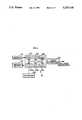
- FIG. 1is a sectional view of an optical system employing excimer laser and a work head for an embodiment of the present invention.
- FIG. 2is a block diagram illustrating a structure of a computer shown in FIG. 1.
- FIG. 3is a flowchart describing a controlling program of the computer for manufacturing an orifice hole.
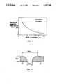
- FIG. 4is a graph showing the relationship between a hole diameter of the orifice hole and a depth of removal by the laser per pulse.
- FIG. 5is a cross-sectional view of the orifice hole formed according to the embodiment.
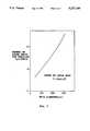
- FIG. 6is a graph showing the relationship between the thickness of the plate and the hole diameter, and between the thickness of the plate and a number of pulse shots.
- FIG. 7is a graph showing the relationship between the hole diameter and the number of pulse shots for removing 5 ⁇ m in depth with the power of the laser being fixed.
- FIG. 8is a graph showing the relationship between the hole diameter and the power of the laser per pulse with the number of pulse shots being fixed.
- FIG. 1shows an optical system A which selects highly phase-matched beams from excimer laser beam 2, and a work head B for forming an orifice hole in a plate 22 by directly applying the laser beam 2 to the plate 22.
- the laser beam 2 generated by a laser generator 1is uniformed by a homogenizer 3. Only central beams 2a having the same phase of the laser beam 2 go through an aperture 4. The central beams 2a are enlarged by the cooperation of a concave lens 5 and a convex lens 6. Again only beams 2b at the central position of the central beams 2a go through another aperture 7. Then the beams 2b are reflected by a mirror 8 to reach a lens 9.
- the lens 9is fixed to a lens holder 11 via screwable retaining rings 13 and 14 with O-shaped rings therebetween.
- the lens holder 11is connected with a nozzle 10.
- the lens holder 11slides along the inner surface of a head holder 12.
- An optical sensor 16is fixed onto a side of the lens holder 11.
- the sensor 16measures a distance n between the sensor 16 and the plate 22. Any type of optical sensor can be utilized if the sensor can measure the distance n.
- a driving systemcontrols the sliding speed and position of the lens holder 11 in the direction of a z axis according to a signal from the sensor 16.
- the driving systemcomprises a sliding device 32 and a computer 21 for actuating the sliding device 32.
- the sliding device 32comprises a driving motor 18, a sliding screw (ball screw) 20 connected to the end of the output axis of the driving motor 18, a female nut 23 for engaging with the sliding screw 20, and an arm 17 for fixing the female nut 23 to the lens holder 11.
- the driving motor 18is, for example, a PG motor, which is longitudinally fixed to the head holder 12 via an arm 19.
- the sliding device 32thus constructed slides the lens holder 11 in the direction of the z axis, controlling the speed of manufacturing the orifice hole according to the distance n.
- assisting gas 25blows from a pipe 24 under the nozzle 10 to blow off particles of the plate 22 generated by applying the laser beam 2.
- Inert gas Armay be employed as the assisting gas 25.
- the computer 21comprises CPU 26, ROM 27, RAM 28, I/O ports 29a through 29c, and a keyboard 30.
- the computer 21controls the slide of the lens holder 11 in accordance with the signal from the sensor 16.
- the computercommunicates with a laser controller 31.
- the laser controller 31controls the number of pulse shots of the laser beam 2 to be applied.
- the ROM 27stores the data for each material employed as the plate 22, and the data for the number of pulse shots required for each laser employed as laser beam 2 to penetrate a unit depth according to the hole diameter.
- FIG. 4shows the relationship between the hole diameter of the orifice hole and the depth of removal by the laser beam 2 per pulse.
- KrF excimer laserhaving wave length ⁇ of 248 ⁇ m and frequency of 100 Hz is utilized as the laser beam 2
- the plate 22is made of Ni.
- the data in the ROM 27 and the hole configurationdetermines the number of pulse shots required to penetrate a depth in accordance with the hole diameter.
- the hole diameteris determined in accordance with an f value and a defocus distance of the lens 9.
- the operation of the computer 21is now described with reference to the flowchart in FIG. 3.
- the RAM 28 of the computer 21stores a controlling program illustrated in the flowchart.
- the RAM 28also stores the data for the number of pulse shots required for each laser employed as the laser beam 2 to penetrate a depth according to the hole diameter, and the data for each material employed as the plate 22.
- the material employed as the plate 22 and the orifice hole (orifice configuration)are selected from the controlling program through the keyboard 30.
- the CPU 26establishes this selection (Step 101).
- the computer 21receives the signal from the sensor 16.
- the signalindicates the distance n between the sensor 16 and the plate 22.
- the CPUcontrols the rotation of the driving motor 18 to correspond the focal point of the lens 9 to the surface of the plate 22 (Step 102).
- the lens holder 11is elevated to a first defocus point corresponding to an initial hole diameter by controlling the driving motor 18 (Step 103).
- the computer 21sends to the laser controller 31 a signal which indicates the number of pulse shots required to penetrate a depth according to the hole diameter.
- the laser controller 31drives the laser generator 1 to generate the laser beam 2 having a predetermined pulse shot frequency of 100 Hz.
- the laser beam 2is applied to the plate 22 through the optical system A and the work head B (Step 104). In this step, the laser power is 200 mJ per pulse.
- the hole diameteris gradually made small by controlling the number of pulse shots with the power of the laser beam 2 being fixed. Then the lens holder 11 is lowered by 5 ⁇ m in the direction of the z axis (Step 105).
- the CPU 26determines whether the Step 104 has executed N times according to the RAM 28 which temporally stores the number of times the Step 104 is executed (Step 106). If no, the process goes back to the Step 104, and the Steps 104 through 106 are repeated until the Step 104 is performed N times. While the Step 104 is performed, the number of pulse shots is controlled according to the relationship between the hole diameter and the number of pulse shots for removing 5 ⁇ m with the power of the laser beam 2 being fixed as shown in FIG. 7. The data of the number of pulse shots in accordance with the hole diameter are stored in the RAM 28 in advance. The number of pulse shots are thus changed every time the lens holder 11 is lowered by 5 ⁇ m in accordance with the data in the RAM 28.
- FIG. 5shows the section of the orifice hole thus formed.
- the Step 104is repeated twenty times.
- the number Nis the number of times the Step 104 is to be performed to achieve the desired depth and is determined according to the thickness of the plate 22 and the depth of removal by the laser beam 2 per pulse.
- the lens holder 11may be lowered more or less than 5 ⁇ m in accordance with the configuration of the hole, the thickness of the plate 22, or other conditions.
- the lens holder 11may be lowered by 1 ⁇ m to form an orifice hole having a more smooth curve. In this case, the adjustment of the number of pulse shots in Step 104 is required.
- the power of laser beammay be changed according to the hole diameter with the number of pulse shots being fixed.
- FIG. 8shows the power of the laser beam 2 per pulse according to the hole diameter, in which the first number of pulse shots of twenty-times is fixed and the power of laser beam 2 is changed every time the lens holder 11 is lowered by 5 ⁇ m.
- the data of the power of laser beam 2are stored in the RAM 28 as in the above case.
- the depth of removal by the laser beam 2 per pulseis fixed, the depth of the orifice hole becomes deeper as the hole diameter becomes smaller. Therefore, the depth of removal per pulse is adjusted according to the hole diameter to fix the depth of the orifice hole.
- the plate 22may be put on a numerically controlled table (NC table), which is moved in the direction of the z axis to change the spot diameter of the laser beam 2.
- NC tablenumerically controlled table
- YAG laser or alexandrite lasermay be employed as the laser beam 2 instead of the excimer laser.
- the device for manufacturing a nozzle of the present inventionchanges the spot diameter of the laser beam 2 on the plate 22. Therefore, the time period for forming the orifice hole can be shortened.
Landscapes
- Physics & Mathematics (AREA)
- Optics & Photonics (AREA)
- Engineering & Computer Science (AREA)
- Plasma & Fusion (AREA)
- Mechanical Engineering (AREA)
- Manufacturing & Machinery (AREA)
- Particle Formation And Scattering Control In Inkjet Printers (AREA)
- Laser Beam Processing (AREA)
Abstract
Description
This invention relates to a device for manufacturing a nozzle utilized in an ink jet printer and its manufacturing method.
Currently, a hole of a nozzle employed in an ink jet device such as a printer has an orifice configuration which gradually tapers, in order to flow liquid ink and discharge it through the hole smoothly. Since such an orifice hole is difficult to manufacture with a conventional drill, so the hole is usually formed by plating or electroforming.
However, since the orifice hole is formed in a plate about 100 μm in thickness, the orifice hole formed by plating or electroforming is difficult to be formed accurately. Further, forming the orifice hole takes several hours, which makes the mass production of the nozzle impossible and adds to the manufacturing cost.
An object of the instant invention is to solve the aforementioned problem by providing a method for manufacturing a nozzle utilized in an ink jet printer, in which the time period for manufacturing an orifice hole of the nozzle is shortened.
Another object of the invention is to provide a device for manufacturing a nozzle utilized in an ink jet printer, in which the time period for manufacturing an orifice hole of the nozzle is shortened.
To attain the first object, the method of the present invention comprises a step to change a spot diameter of a laser beam on a plate in which an orifice hole is manufactured.
The second object can be attained by a device comprising a laser beam generating means for generating a laser beam, a work head comprising a lens to focus the laser beam on a plate, a driving means to move the work head upward and downward, a position detecting means for sending a signal indicating a position of the work head, and a controlling means for controlling an amount of the laser beam to be applied according to the signal from the position detecting means.
The nozzle forming device of the present invention thus constructed changes the spot diameter of the laser beam on the plate. Therefore, the time period for forming the orifice hole of a nozzle is shortened.
FIG. 1 is a sectional view of an optical system employing excimer laser and a work head for an embodiment of the present invention.
FIG. 2 is a block diagram illustrating a structure of a computer shown in FIG. 1.
FIG. 3 is a flowchart describing a controlling program of the computer for manufacturing an orifice hole.
FIG. 4 is a graph showing the relationship between a hole diameter of the orifice hole and a depth of removal by the laser per pulse.
FIG. 5 is a cross-sectional view of the orifice hole formed according to the embodiment.
FIG. 6 is a graph showing the relationship between the thickness of the plate and the hole diameter, and between the thickness of the plate and a number of pulse shots.
FIG. 7 is a graph showing the relationship between the hole diameter and the number of pulse shots for removing 5 μm in depth with the power of the laser being fixed.
FIG. 8 is a graph showing the relationship between the hole diameter and the power of the laser per pulse with the number of pulse shots being fixed.
A preferred embodiment is now described with reference to the drawings.
FIG. 1 shows an optical system A which selects highly phase-matched beams fromexcimer laser beam 2, and a work head B for forming an orifice hole in aplate 22 by directly applying thelaser beam 2 to theplate 22.
Referring to the optical system A first, thelaser beam 2 generated by alaser generator 1 is uniformed by ahomogenizer 3. Onlycentral beams 2a having the same phase of thelaser beam 2 go through anaperture 4. Thecentral beams 2a are enlarged by the cooperation of aconcave lens 5 and aconvex lens 6. Again onlybeams 2b at the central position of thecentral beams 2a go through another aperture 7. Then thebeams 2b are reflected by a mirror 8 to reach alens 9.
Turning to the work head B, thelens 9 is fixed to alens holder 11 viascrewable retaining rings lens holder 11 is connected with anozzle 10. Thelens holder 11 slides along the inner surface of ahead holder 12. Anoptical sensor 16 is fixed onto a side of thelens holder 11. Thesensor 16 measures a distance n between thesensor 16 and theplate 22. Any type of optical sensor can be utilized if the sensor can measure the distance n.
A driving system controls the sliding speed and position of thelens holder 11 in the direction of a z axis according to a signal from thesensor 16. The driving system comprises asliding device 32 and acomputer 21 for actuating thesliding device 32. Thesliding device 32 comprises adriving motor 18, a sliding screw (ball screw) 20 connected to the end of the output axis of the drivingmotor 18, afemale nut 23 for engaging with thesliding screw 20, and an arm 17 for fixing thefemale nut 23 to thelens holder 11. Thedriving motor 18 is, for example, a PG motor, which is longitudinally fixed to thehead holder 12 via anarm 19. Thesliding device 32 thus constructed slides thelens holder 11 in the direction of the z axis, controlling the speed of manufacturing the orifice hole according to the distance n.
Further, assistinggas 25 blows from a pipe 24 under thenozzle 10 to blow off particles of theplate 22 generated by applying thelaser beam 2. Inert gas Ar may be employed as the assistinggas 25.
In FIG. 2, thecomputer 21 comprisesCPU 26,ROM 27,RAM 28, I/O ports 29a through 29c, and akeyboard 30. Thecomputer 21 controls the slide of thelens holder 11 in accordance with the signal from thesensor 16. The computer communicates with alaser controller 31. Thelaser controller 31 controls the number of pulse shots of thelaser beam 2 to be applied.
TheROM 27 stores the data for each material employed as theplate 22, and the data for the number of pulse shots required for each laser employed aslaser beam 2 to penetrate a unit depth according to the hole diameter. FIG. 4 shows the relationship between the hole diameter of the orifice hole and the depth of removal by thelaser beam 2 per pulse. In FIG. 4, KrF excimer laser having wave length λ of 248 μm and frequency of 100 Hz is utilized as thelaser beam 2, and theplate 22 is made of Ni. The data in theROM 27 and the hole configuration determines the number of pulse shots required to penetrate a depth in accordance with the hole diameter. The hole diameter is determined in accordance with an f value and a defocus distance of thelens 9.
The operation of thecomputer 21 is now described with reference to the flowchart in FIG. 3. TheRAM 28 of thecomputer 21 stores a controlling program illustrated in the flowchart. TheRAM 28 also stores the data for the number of pulse shots required for each laser employed as thelaser beam 2 to penetrate a depth according to the hole diameter, and the data for each material employed as theplate 22.
Upon operation, the material employed as theplate 22 and the orifice hole (orifice configuration) are selected from the controlling program through thekeyboard 30. TheCPU 26 establishes this selection (Step 101).
Thecomputer 21 receives the signal from thesensor 16. The signal indicates the distance n between thesensor 16 and theplate 22. According to the signal, the CPU controls the rotation of the drivingmotor 18 to correspond the focal point of thelens 9 to the surface of the plate 22 (Step 102).
To form the orifice hole selected in Step 101, thelens holder 11 is elevated to a first defocus point corresponding to an initial hole diameter by controlling the driving motor 18 (Step 103).
Then the orifice hole is worked. Thecomputer 21 sends to the laser controller 31 a signal which indicates the number of pulse shots required to penetrate a depth according to the hole diameter. Thelaser controller 31 drives thelaser generator 1 to generate thelaser beam 2 having a predetermined pulse shot frequency of 100 Hz. Thelaser beam 2 is applied to theplate 22 through the optical system A and the work head B (Step 104). In this step, the laser power is 200 mJ per pulse. The hole diameter is gradually made small by controlling the number of pulse shots with the power of thelaser beam 2 being fixed. Then thelens holder 11 is lowered by 5 μm in the direction of the z axis (Step 105). TheCPU 26 determines whether the Step 104 has executed N times according to theRAM 28 which temporally stores the number of times the Step 104 is executed (Step 106). If no, the process goes back to the Step 104, and the Steps 104 through 106 are repeated until the Step 104 is performed N times. While the Step 104 is performed, the number of pulse shots is controlled according to the relationship between the hole diameter and the number of pulse shots for removing 5 μm with the power of thelaser beam 2 being fixed as shown in FIG. 7. The data of the number of pulse shots in accordance with the hole diameter are stored in theRAM 28 in advance. The number of pulse shots are thus changed every time thelens holder 11 is lowered by 5 μm in accordance with the data in theRAM 28.
When the CPU determines yes at the Step 106, the process ends. FIG. 5 shows the section of the orifice hole thus formed.
According to this embodiment in which the hole diameter changes from 300 μm to 50 μm, since the thickness of theplate 22 is 100 μm, the Step 104 is repeated twenty times. Thus, the number N is the number of times the Step 104 is to be performed to achieve the desired depth and is determined according to the thickness of theplate 22 and the depth of removal by thelaser beam 2 per pulse.
Thelens holder 11 may be lowered more or less than 5 μm in accordance with the configuration of the hole, the thickness of theplate 22, or other conditions. For example, thelens holder 11 may be lowered by 1 μm to form an orifice hole having a more smooth curve. In this case, the adjustment of the number of pulse shots in Step 104 is required.
Further, instead of changing the number of pulse shots, the power of laser beam may be changed according to the hole diameter with the number of pulse shots being fixed. FIG. 8 shows the power of thelaser beam 2 per pulse according to the hole diameter, in which the first number of pulse shots of twenty-times is fixed and the power oflaser beam 2 is changed every time thelens holder 11 is lowered by 5 μm. The data of the power oflaser beam 2 are stored in theRAM 28 as in the above case.
Moreover, when the depth of removal by thelaser beam 2 per pulse is fixed, the depth of the orifice hole becomes deeper as the hole diameter becomes smaller. Therefore, the depth of removal per pulse is adjusted according to the hole diameter to fix the depth of the orifice hole.
The present invention may be subject to many modifications and changes without departing from the spirit or essential characteristics thereof. For example, theplate 22 may be put on a numerically controlled table (NC table), which is moved in the direction of the z axis to change the spot diameter of thelaser beam 2. Further, YAG laser or alexandrite laser may be employed as thelaser beam 2 instead of the excimer laser.
As aforementioned, the device for manufacturing a nozzle of the present invention changes the spot diameter of thelaser beam 2 on theplate 22. Therefore, the time period for forming the orifice hole can be shortened.
Claims (24)
1. A method for manufacturing a nozzle comprising the step of:
gradually changing a spot diameter of a laser beam impinging on a plate in which an orifice hole is to be formed according to a required hole size.
2. A method for manufacturing a nozzle comprising the steps of:
setting penetration parameters for manufacturing said nozzle;
impinging a laser beam on a plate in which a nozzle is to be formed;
determining the beam characteristics of said laser beam on said plate;
comparing said beam characteristics to said penetration parameters; and
controlling said beam characteristics according to said comparing step to achieve said penetration parameters.
3. The method of claim 2, wherein the determining step includes determining a spot diameter of said beam and said comparing step includes comparing the spot diameter determined in the determining step to a spot diameter specified according to said penetration parameters set in said setting step.
4. The method of claim 3, further comprising the step of:
pulsing said laser beam for a defined number of pulse shots to remove a penetration depth of plate material from said plate according to penetration parameters comprising said spot diameter.
5. The method of claim 4, wherein said penetration parameters further comprise a laser type employed to produce said laser beam.
6. The method of claim 4, wherein said penetration parameters further comprise a material type of said plate material.
7. The method of claim 4, further comprising the step of:
repeating said changing and pulsing steps to form said orifice hole, said orifice hole having an orifice depth based on a summation of the penetration depths of said repeated pulsing steps.
8. The method of claim 4, further comprising the step of:
repeating said changing and pulsing steps to form said orifice hole, said orifice hole having an orifice depth based on a summation of the penetration depths of said repeated pulsing steps, and said orifice hole having a predetermined taper based on said spot diameters and said penetration depths of said repeated changing and pulsing steps.
9. The method of claim 2, wherein the determining step includes determining focus of said beam and said comparing step includes comparing the focus determined in the determining step to a focus specified according to said penetration parameters set in said setting step.
10. The method of claim 2, wherein the determining step includes determining pulse number to depth of said beam and said comparing step includes comparing the pulse number to depth determined in the determining step to a pulse number to depth specified according to said penetration parameters set in said setting step.
11. The method of claim 2, wherein the setting step includes setting penetration parameters according to plate material and orifice configuration of said nozzle.
12. The method of claim 2, wherein the determining step includes determining laser beam power of said beam and said comparing step includes comparing the laser beam power to a laser beam power specified according to said penetration parameters set in said setting step.
13. The method of claim 2, wherein the determining step includes determining spot diameter of said beam and said comparing step includes comparing the spot diameter determined in the determining step to a spot diameter specified according to a required hole size set in said setting step.
14. A device for manufacturing a nozzle comprising:
laser beam generating means for generating a laser beam;
detecting means for determining nozzle forming beam characteristics of a laser beam generated by said generating means and for sending a signal according to said characteristics; and
controlling means for controlling said laser beam generating means according to said signal from said detecting means.
15. The device of claim 14 further comprising:
means for pulsing said laser beam for a defined number of pulse shots to remove a penetration depth of plate material from said plate according to penetration parameters comprising said spot diameter.
16. The device of claim 15 further comprising:
means for repeatedly activating said means for changing and pulsing to form said orifice hole, said orifice hole having an orifice depth based on a summation of the penetration depths produced by said repeatedly activated means for pulsing.
17. The device of claim 16 wherein said means for changing comprises:
a lens for focusing said laser beam on said plate;
a work head comprising said lens; and
driving means for moving said lens relative to said plate.
18. The device of claim 16 wherein means for pulsing comprises:
a lens for focusing said laser beam on said plate;
position detecting means for producing a distance signal indicating a distance between said lens and said plate; and
controlling means for controlling said laser beam generating means so as to determine said defined number of pulse shots according to said distance signal.
19. The device of claim 15, wherein the number of pulse shots is changed in accordance with the change of the hole diameter of the orifice hole based on a predetermined simulation with the power of the laser beam being fixed.
20. The device of claim 15, wherein the power of laser beam is changed in accordance with the hole diameter of the orifice hole based on a predetermined simulation with the number of pulse shots being fixed.
21. The device of claim 14, wherein said controlling means comprises a means for changing the spot diameter of said laser beam.
22. The device of claim 14, further comprising setting means for setting nozzle forming beam characteristics for manufacturing said nozzle.
23. The device of claim 22, wherein the controlling means further comprises comparing means for comparing detected nozzle forming beam characteristics detected by the detecting means with set beam characteristics set by the setting means to determine said signal to said controlling means.
24. A jet nozzle comprising an orifice hole manufactured by the method of claim 1.
Applications Claiming Priority (2)
| Application Number | Priority Date | Filing Date | Title |
|---|---|---|---|
| JP2-267120 | 1990-10-04 | ||
| JP2267120AJP2797684B2 (en) | 1990-10-04 | 1990-10-04 | Nozzle manufacturing method and manufacturing apparatus |
Publications (1)
| Publication Number | Publication Date |
|---|---|
| US5237148Atrue US5237148A (en) | 1993-08-17 |
Family
ID=17440349
Family Applications (1)
| Application Number | Title | Priority Date | Filing Date |
|---|---|---|---|
| US07/770,358Expired - LifetimeUS5237148A (en) | 1990-10-04 | 1991-10-03 | Device for manufacturing a nozzle and its manufacturing method |
Country Status (2)
| Country | Link |
|---|---|
| US (1) | US5237148A (en) |
| JP (1) | JP2797684B2 (en) |
Cited By (52)
| Publication number | Priority date | Publication date | Assignee | Title |
|---|---|---|---|---|
| US5298716A (en)* | 1992-09-22 | 1994-03-29 | Mitsubishi Denki Kabushiki Kaisha | Laser processing head and method for operation thereof |
| US5376770A (en)* | 1992-01-13 | 1994-12-27 | Maho Aktiengesellschaft | Process and device for machining workpieces by means of a laser beam |
| GB2313079A (en)* | 1996-05-16 | 1997-11-19 | British Aerospace | Two stage drilling by laser irradiation |
| WO1998004813A1 (en)* | 1996-07-31 | 1998-02-05 | Kvaerner Asa | An outlet valve for combustion engines and a production method therefor |
| US5932118A (en)* | 1994-05-16 | 1999-08-03 | Sanyo Electric Co., Ltd. | Photoprocessing method |
| EP0976487A1 (en)* | 1998-07-30 | 2000-02-02 | Societe Nationale D'etude Et De Construction De Moteurs D'aviation "Snecma" | Process for excimer laser machining of holes or forms with variable shapes |
| US6070813A (en)* | 1998-08-11 | 2000-06-06 | Caterpillar Inc. | Laser drilled nozzle in a tip of a fuel injector |
| US6075222A (en)* | 1996-11-13 | 2000-06-13 | Canon Kabushiki Kaisha | Method for manufacturing a liquid jet recording head |
| US6089698A (en)* | 1992-02-05 | 2000-07-18 | Xaar Technology Limited | Nozzles and methods of and apparatus for forming nozzles |
| US6130009A (en)* | 1994-01-03 | 2000-10-10 | Litel Instruments | Apparatus and process for nozzle production utilizing computer generated holograms |
| US6201213B1 (en)* | 1996-10-01 | 2001-03-13 | Mitsubishi Denki Kabushiki Kaisha | Method and device for machining a wiring board utilizing light shielding of a laser beam to select a machined tapering |
| US6211486B1 (en)* | 1997-07-04 | 2001-04-03 | Canon Kabushiki Kaisha | Method of making ink jet recording head with tapered orifice |
| US6371600B1 (en) | 1998-06-15 | 2002-04-16 | Lexmark International, Inc. | Polymeric nozzle plate |
| EP1295647A1 (en)* | 2001-09-24 | 2003-03-26 | The Technology Partnership Public Limited Company | Nozzles in perforate membranes and their manufacture |
| US6600132B2 (en) | 2001-07-31 | 2003-07-29 | John James Horsting | Method and apparatus to generate orifice disk entry geometry |
| US6603095B2 (en) | 2001-07-23 | 2003-08-05 | Siemens Automotive Corporation | Apparatus and method of overlapping formation of chamfers and orifices by laser light |
| US6623103B2 (en) | 2001-04-10 | 2003-09-23 | Lexmark International, Inc. | Laser ablation method for uniform nozzle structure |
| US6635847B2 (en) | 2001-07-31 | 2003-10-21 | Siemens Automotive Corporation | Method of forming orifices and chamfers by collimated and non-collimated light |
| US6642476B2 (en) | 2001-07-23 | 2003-11-04 | Siemens Automative Corporation | Apparatus and method of forming orifices and chamfers for uniform orifice coefficient and surface properties by laser |
| US20030217995A1 (en)* | 2002-05-23 | 2003-11-27 | Yosuke Toyofuku | Laser processing method using ultra-short pulse laser beam |
| WO2004009284A1 (en)* | 2002-07-23 | 2004-01-29 | Matsushita Electric Industrial Co., Ltd. | Laser processing method and laser processing apparatus |
| US6720526B2 (en) | 2001-07-31 | 2004-04-13 | Siemens Automotive Corporation | Method and apparatus to form dimensionally consistent orifices and chamfers by laser using spatial filters |
| US6740847B1 (en) | 2003-03-10 | 2004-05-25 | Siemens Vdo Automotive Corporation | Method of forming multiple machining spots by a single laser |
| US6777641B2 (en) | 2002-04-16 | 2004-08-17 | W.A. Whitney Co. | Method and apparatus for laser piercing and cutting metal sheet and plate |
| US20040183855A1 (en)* | 2001-11-30 | 2004-09-23 | Chen-Hsiung Cheng | Method of laser milling using constant tool path algorithm |
| US20050247894A1 (en)* | 2004-05-05 | 2005-11-10 | Watkins Charles M | Systems and methods for forming apertures in microfeature workpieces |
| EP1448336A4 (en)* | 2001-11-30 | 2006-03-15 | Matsushita Electric Industrial Co Ltd | Method of laser milling using constant tool path algorithm |
| US20060201478A1 (en)* | 2005-03-09 | 2006-09-14 | Vachon John T | Internal combustion engine |
| US20070045826A1 (en)* | 2005-09-01 | 2007-03-01 | Micron Technology, Inc. | Microfeature workpiece substrates having through-substrate vias, and associated methods of formation |
| US20070049016A1 (en)* | 2005-09-01 | 2007-03-01 | Micron Technology, Inc. | Microfeature workpieces and methods for forming interconnects in microfeature workpieces |
| US20070045120A1 (en)* | 2005-09-01 | 2007-03-01 | Micron Technology, Inc. | Methods and apparatus for filling features in microfeature workpieces |
| US20070169741A1 (en)* | 2005-03-09 | 2007-07-26 | Vachon John T | Internal combustion engine and operating method therefor |
| US20070267754A1 (en)* | 2005-09-01 | 2007-11-22 | Micron Technology, Inc. | Microfeature workpieces and methods for forming interconnects in microfeature workpieces |
| US20070281473A1 (en)* | 2006-06-01 | 2007-12-06 | Micron Technology, Inc. | Microelectronic workpieces and methods and systems for forming interconnects in microelectronic workpieces |
| US20080054444A1 (en)* | 2006-08-31 | 2008-03-06 | Micron Technology, Inc. | Microfeature workpieces having interconnects and conductive backplanes, and associated systems and methods |
| WO2008025811A1 (en) | 2006-08-30 | 2008-03-06 | Thyssenkrupp Steel Ag | Method and device for processing workpieces with the help of a laser beam |
| US20080111213A1 (en)* | 2004-09-02 | 2008-05-15 | Micron Technology, Inc. | Through-wafer interconnects for photoimager and memory wafers |
| US20090057912A1 (en)* | 2007-08-31 | 2009-03-05 | Micron Technology, Inc. | Partitioned through-layer via and associated systems and methods |
| US7531453B2 (en) | 2004-06-29 | 2009-05-12 | Micron Technology, Inc. | Microelectronic devices and methods for forming interconnects in microelectronic devices |
| US20090146312A1 (en)* | 2007-12-06 | 2009-06-11 | Micron Technology, Inc. | Methods for forming interconnects in microelectronic workpieces and microelectronic workpieces formed using such methods |
| US20090294423A1 (en)* | 2008-05-28 | 2009-12-03 | Caterpillar Inc. | Manufacturing system having delivery media and grin lens |
| US20090294416A1 (en)* | 2008-05-28 | 2009-12-03 | Caterpillar Inc. | Laser manufacturing system having real-time feedback |
| US20090294421A1 (en)* | 2008-05-28 | 2009-12-03 | Caterpillar Inc. | Manufacturing system for producing reverse-tapered orifice |
| US7629249B2 (en) | 2006-08-28 | 2009-12-08 | Micron Technology, Inc. | Microfeature workpieces having conductive interconnect structures formed by chemically reactive processes, and associated systems and methods |
| US20090321395A1 (en)* | 2007-08-15 | 2009-12-31 | Caterpillar Inc. | Variable focus laser machining system |
| US7759800B2 (en) | 2003-11-13 | 2010-07-20 | Micron Technology, Inc. | Microelectronics devices, having vias, and packaged microelectronic devices having vias |
| US7795134B2 (en) | 2005-06-28 | 2010-09-14 | Micron Technology, Inc. | Conductive interconnect structures and formation methods using supercritical fluids |
| US20100269783A1 (en)* | 2005-03-09 | 2010-10-28 | Carl-Anders Hergart | Internal combustion engine and operating method therefor |
| US20100276520A1 (en)* | 2009-04-29 | 2010-11-04 | Caterpillar Inc. | Indirect laser induced residual stress in a fuel system component and fuel system using same |
| US8084866B2 (en) | 2003-12-10 | 2011-12-27 | Micron Technology, Inc. | Microelectronic devices and methods for filling vias in microelectronic devices |
| US8322031B2 (en) | 2004-08-27 | 2012-12-04 | Micron Technology, Inc. | Method of manufacturing an interposer |
| US20140283987A1 (en)* | 2013-03-19 | 2014-09-25 | Systems And Materials Research Corporation | Method and apparatus to apply a fill material to a substrate |
Families Citing this family (2)
| Publication number | Priority date | Publication date | Assignee | Title |
|---|---|---|---|---|
| US5637244A (en)* | 1993-05-13 | 1997-06-10 | Podarok International, Inc. | Method and apparatus for creating an image by a pulsed laser beam inside a transparent material |
| US8237080B2 (en) | 2008-03-27 | 2012-08-07 | Electro Scientific Industries, Inc | Method and apparatus for laser drilling holes with Gaussian pulses |
Citations (5)
| Publication number | Priority date | Publication date | Assignee | Title |
|---|---|---|---|---|
| JPS5949113A (en)* | 1982-09-14 | 1984-03-21 | 東芝シリコ−ン株式会社 | Method of imparting lubricating property to silver blank |
| GB2236973A (en)* | 1989-10-17 | 1991-04-24 | Bosch Gmbh Robert | Producing high-precision through bores by laser radiation |
| GB2239206A (en)* | 1989-12-21 | 1991-06-26 | Bosch Gmbh Robert | Measuring the size of through-bores during boring |
| US5061839A (en)* | 1990-03-06 | 1991-10-29 | Mitsubishi Denki K.K. | Laser beam machining apparatus |
| US5063280A (en)* | 1989-07-24 | 1991-11-05 | Canon Kabushiki Kaisha | Method and apparatus for forming holes into printed circuit board |
Family Cites Families (2)
| Publication number | Priority date | Publication date | Assignee | Title |
|---|---|---|---|---|
| JPS5817718B2 (en)* | 1973-03-28 | 1983-04-08 | 株式会社東芝 | Lasaniyoru Anaake Kakohouhou |
| JPS61296984A (en)* | 1985-06-27 | 1986-12-27 | Mitsubishi Electric Corp | Laser beam processing device |
- 1990
- 1990-10-04JPJP2267120Apatent/JP2797684B2/ennot_activeExpired - Fee Related
- 1991
- 1991-10-03USUS07/770,358patent/US5237148A/ennot_activeExpired - Lifetime
Patent Citations (5)
| Publication number | Priority date | Publication date | Assignee | Title |
|---|---|---|---|---|
| JPS5949113A (en)* | 1982-09-14 | 1984-03-21 | 東芝シリコ−ン株式会社 | Method of imparting lubricating property to silver blank |
| US5063280A (en)* | 1989-07-24 | 1991-11-05 | Canon Kabushiki Kaisha | Method and apparatus for forming holes into printed circuit board |
| GB2236973A (en)* | 1989-10-17 | 1991-04-24 | Bosch Gmbh Robert | Producing high-precision through bores by laser radiation |
| GB2239206A (en)* | 1989-12-21 | 1991-06-26 | Bosch Gmbh Robert | Measuring the size of through-bores during boring |
| US5061839A (en)* | 1990-03-06 | 1991-10-29 | Mitsubishi Denki K.K. | Laser beam machining apparatus |
Cited By (109)
| Publication number | Priority date | Publication date | Assignee | Title |
|---|---|---|---|---|
| US5376770A (en)* | 1992-01-13 | 1994-12-27 | Maho Aktiengesellschaft | Process and device for machining workpieces by means of a laser beam |
| US6089698A (en)* | 1992-02-05 | 2000-07-18 | Xaar Technology Limited | Nozzles and methods of and apparatus for forming nozzles |
| US5298716A (en)* | 1992-09-22 | 1994-03-29 | Mitsubishi Denki Kabushiki Kaisha | Laser processing head and method for operation thereof |
| US6130009A (en)* | 1994-01-03 | 2000-10-10 | Litel Instruments | Apparatus and process for nozzle production utilizing computer generated holograms |
| US5932118A (en)* | 1994-05-16 | 1999-08-03 | Sanyo Electric Co., Ltd. | Photoprocessing method |
| GB2313079A (en)* | 1996-05-16 | 1997-11-19 | British Aerospace | Two stage drilling by laser irradiation |
| WO1998004813A1 (en)* | 1996-07-31 | 1998-02-05 | Kvaerner Asa | An outlet valve for combustion engines and a production method therefor |
| US6420676B2 (en) | 1996-10-01 | 2002-07-16 | Mitsubishi Denki Kabushiki Kaisha | Method for machining wiring board with laser beam and device for same |
| US6201213B1 (en)* | 1996-10-01 | 2001-03-13 | Mitsubishi Denki Kabushiki Kaisha | Method and device for machining a wiring board utilizing light shielding of a laser beam to select a machined tapering |
| US6075222A (en)* | 1996-11-13 | 2000-06-13 | Canon Kabushiki Kaisha | Method for manufacturing a liquid jet recording head |
| US6568791B2 (en) | 1997-07-04 | 2003-05-27 | Canon Kabushiki Kaisha | Ink jet recording head and a method of manufacture therefor |
| US6211486B1 (en)* | 1997-07-04 | 2001-04-03 | Canon Kabushiki Kaisha | Method of making ink jet recording head with tapered orifice |
| US6371600B1 (en) | 1998-06-15 | 2002-04-16 | Lexmark International, Inc. | Polymeric nozzle plate |
| FR2781707A1 (en)* | 1998-07-30 | 2000-02-04 | Snecma | EXCIMERATED LASER MACHINING PROCESS OF HOLES OR SHAPES WITH VARIABLE PROFILE |
| EP0976487A1 (en)* | 1998-07-30 | 2000-02-02 | Societe Nationale D'etude Et De Construction De Moteurs D'aviation "Snecma" | Process for excimer laser machining of holes or forms with variable shapes |
| US6070813A (en)* | 1998-08-11 | 2000-06-06 | Caterpillar Inc. | Laser drilled nozzle in a tip of a fuel injector |
| US6623103B2 (en) | 2001-04-10 | 2003-09-23 | Lexmark International, Inc. | Laser ablation method for uniform nozzle structure |
| US6603095B2 (en) | 2001-07-23 | 2003-08-05 | Siemens Automotive Corporation | Apparatus and method of overlapping formation of chamfers and orifices by laser light |
| US6642476B2 (en) | 2001-07-23 | 2003-11-04 | Siemens Automative Corporation | Apparatus and method of forming orifices and chamfers for uniform orifice coefficient and surface properties by laser |
| US6600132B2 (en) | 2001-07-31 | 2003-07-29 | John James Horsting | Method and apparatus to generate orifice disk entry geometry |
| US6635847B2 (en) | 2001-07-31 | 2003-10-21 | Siemens Automotive Corporation | Method of forming orifices and chamfers by collimated and non-collimated light |
| US6720526B2 (en) | 2001-07-31 | 2004-04-13 | Siemens Automotive Corporation | Method and apparatus to form dimensionally consistent orifices and chamfers by laser using spatial filters |
| EP1295647A1 (en)* | 2001-09-24 | 2003-03-26 | The Technology Partnership Public Limited Company | Nozzles in perforate membranes and their manufacture |
| WO2003026832A1 (en) | 2001-09-24 | 2003-04-03 | The Technology Partnership Plc | Forming a perforate membrane by laser drilling and a subsequent electro-polishing step |
| US20050006359A1 (en)* | 2001-09-24 | 2005-01-13 | Blakey David Mark | Forming a perforate membrane by laser drilling and a subsequent electro-polishing step |
| US7316067B2 (en)* | 2001-09-24 | 2008-01-08 | The Technology Partnership | Forming a perforate membrane by laser drilling and a subsequent electro-polishing step |
| US20040182831A1 (en)* | 2001-11-30 | 2004-09-23 | Chen-Hsiung Cheng | Method of laser milling using constant tool path algorithm |
| US20040183855A1 (en)* | 2001-11-30 | 2004-09-23 | Chen-Hsiung Cheng | Method of laser milling using constant tool path algorithm |
| EP1448336A4 (en)* | 2001-11-30 | 2006-03-15 | Matsushita Electric Industrial Co Ltd | Method of laser milling using constant tool path algorithm |
| US6777641B2 (en) | 2002-04-16 | 2004-08-17 | W.A. Whitney Co. | Method and apparatus for laser piercing and cutting metal sheet and plate |
| US20030217995A1 (en)* | 2002-05-23 | 2003-11-27 | Yosuke Toyofuku | Laser processing method using ultra-short pulse laser beam |
| WO2004009284A1 (en)* | 2002-07-23 | 2004-01-29 | Matsushita Electric Industrial Co., Ltd. | Laser processing method and laser processing apparatus |
| US20040206734A1 (en)* | 2003-03-10 | 2004-10-21 | Siemens Vdo Automotive Corporation | Laser machining system for forming multiple machining spots by a single laser |
| US6740847B1 (en) | 2003-03-10 | 2004-05-25 | Siemens Vdo Automotive Corporation | Method of forming multiple machining spots by a single laser |
| US7161113B2 (en) | 2003-03-10 | 2007-01-09 | Siemens Vdo Automotive Corporation | Laser machining system for forming multiple machining spots by a single laser |
| US7759800B2 (en) | 2003-11-13 | 2010-07-20 | Micron Technology, Inc. | Microelectronics devices, having vias, and packaged microelectronic devices having vias |
| US9653420B2 (en) | 2003-11-13 | 2017-05-16 | Micron Technology, Inc. | Microelectronic devices and methods for filling vias in microelectronic devices |
| US8748311B2 (en) | 2003-12-10 | 2014-06-10 | Micron Technology, Inc. | Microelectronic devices and methods for filing vias in microelectronic devices |
| US8084866B2 (en) | 2003-12-10 | 2011-12-27 | Micron Technology, Inc. | Microelectronic devices and methods for filling vias in microelectronic devices |
| US11177175B2 (en) | 2003-12-10 | 2021-11-16 | Micron Technology, Inc. | Microelectronic devices and methods for filling vias in microelectronic devices |
| US20060186097A1 (en)* | 2004-05-05 | 2006-08-24 | Micron Technology, Inc. | Systems and methods for forming apertures in microfeature workpieces |
| US8686313B2 (en) | 2004-05-05 | 2014-04-01 | Micron Technology, Inc. | System and methods for forming apertures in microfeature workpieces |
| US8664562B2 (en) | 2004-05-05 | 2014-03-04 | Micron Technology, Inc. | Systems and methods for forming apertures in microfeature workpieces |
| US10010977B2 (en) | 2004-05-05 | 2018-07-03 | Micron Technology, Inc. | Systems and methods for forming apertures in microfeature workpieces |
| US8536485B2 (en)* | 2004-05-05 | 2013-09-17 | Micron Technology, Inc. | Systems and methods for forming apertures in microfeature workpieces |
| US20050247894A1 (en)* | 2004-05-05 | 2005-11-10 | Watkins Charles M | Systems and methods for forming apertures in microfeature workpieces |
| US20060191882A1 (en)* | 2004-05-05 | 2006-08-31 | Micron Technology, Inc. | Systems and methods for forming apertures in microfeature workpieces |
| US9452492B2 (en) | 2004-05-05 | 2016-09-27 | Micron Technology, Inc. | Systems and methods for forming apertures in microfeature workpieces |
| US7531453B2 (en) | 2004-06-29 | 2009-05-12 | Micron Technology, Inc. | Microelectronic devices and methods for forming interconnects in microelectronic devices |
| US7829976B2 (en) | 2004-06-29 | 2010-11-09 | Micron Technology, Inc. | Microelectronic devices and methods for forming interconnects in microelectronic devices |
| US8322031B2 (en) | 2004-08-27 | 2012-12-04 | Micron Technology, Inc. | Method of manufacturing an interposer |
| US20080111213A1 (en)* | 2004-09-02 | 2008-05-15 | Micron Technology, Inc. | Through-wafer interconnects for photoimager and memory wafers |
| US8502353B2 (en) | 2004-09-02 | 2013-08-06 | Micron Technology, Inc. | Through-wafer interconnects for photoimager and memory wafers |
| US20110233777A1 (en)* | 2004-09-02 | 2011-09-29 | Micron Technology, Inc. | Through-wafer interconnects for photoimager and memory wafers |
| US7956443B2 (en) | 2004-09-02 | 2011-06-07 | Micron Technology, Inc. | Through-wafer interconnects for photoimager and memory wafers |
| US8669179B2 (en) | 2004-09-02 | 2014-03-11 | Micron Technology, Inc. | Through-wafer interconnects for photoimager and memory wafers |
| US7683458B2 (en) | 2004-09-02 | 2010-03-23 | Micron Technology, Inc. | Through-wafer interconnects for photoimager and memory wafers |
| US20100171217A1 (en)* | 2004-09-02 | 2010-07-08 | Micron Technology, Inc. | Through-wafer interconnects for photoimager and memory wafers |
| US8069835B2 (en) | 2005-03-09 | 2011-12-06 | Caterpillar Inc. | Internal combustion engine and operating method therefor |
| US20060201478A1 (en)* | 2005-03-09 | 2006-09-14 | Vachon John T | Internal combustion engine |
| US7597084B2 (en) | 2005-03-09 | 2009-10-06 | Caterpillar Inc. | Internal combustion engine and operating method therefor |
| US20070169741A1 (en)* | 2005-03-09 | 2007-07-26 | Vachon John T | Internal combustion engine and operating method therefor |
| US20100269783A1 (en)* | 2005-03-09 | 2010-10-28 | Carl-Anders Hergart | Internal combustion engine and operating method therefor |
| US7201135B2 (en)* | 2005-03-09 | 2007-04-10 | Caterpillar Inc | Internal combustion engine |
| US8008192B2 (en) | 2005-06-28 | 2011-08-30 | Micron Technology, Inc. | Conductive interconnect structures and formation methods using supercritical fluids |
| US7795134B2 (en) | 2005-06-28 | 2010-09-14 | Micron Technology, Inc. | Conductive interconnect structures and formation methods using supercritical fluids |
| US9293367B2 (en) | 2005-06-28 | 2016-03-22 | Micron Technology, Inc. | Conductive interconnect structures and formation methods using supercritical fluids |
| US20070045120A1 (en)* | 2005-09-01 | 2007-03-01 | Micron Technology, Inc. | Methods and apparatus for filling features in microfeature workpieces |
| US7622377B2 (en) | 2005-09-01 | 2009-11-24 | Micron Technology, Inc. | Microfeature workpiece substrates having through-substrate vias, and associated methods of formation |
| US20070045826A1 (en)* | 2005-09-01 | 2007-03-01 | Micron Technology, Inc. | Microfeature workpiece substrates having through-substrate vias, and associated methods of formation |
| US20070049016A1 (en)* | 2005-09-01 | 2007-03-01 | Micron Technology, Inc. | Microfeature workpieces and methods for forming interconnects in microfeature workpieces |
| US20070267754A1 (en)* | 2005-09-01 | 2007-11-22 | Micron Technology, Inc. | Microfeature workpieces and methods for forming interconnects in microfeature workpieces |
| US7915736B2 (en) | 2005-09-01 | 2011-03-29 | Micron Technology, Inc. | Microfeature workpieces and methods for forming interconnects in microfeature workpieces |
| US20110079900A1 (en)* | 2005-09-01 | 2011-04-07 | Micron Technology, Inc. | Microfeature workpieces and methods for forming interconnects in microfeature workpieces |
| US11476160B2 (en) | 2005-09-01 | 2022-10-18 | Micron Technology, Inc. | Microfeature workpieces and methods for forming interconnects in microfeature workpieces |
| US12014958B2 (en) | 2005-09-01 | 2024-06-18 | Micron Technology, Inc. | Microfeature workpieces and methods for forming interconnects in microfeature workpieces |
| US7863187B2 (en) | 2005-09-01 | 2011-01-04 | Micron Technology, Inc. | Microfeature workpieces and methods for forming interconnects in microfeature workpieces |
| US7749899B2 (en) | 2006-06-01 | 2010-07-06 | Micron Technology, Inc. | Microelectronic workpieces and methods and systems for forming interconnects in microelectronic workpieces |
| US20070281473A1 (en)* | 2006-06-01 | 2007-12-06 | Micron Technology, Inc. | Microelectronic workpieces and methods and systems for forming interconnects in microelectronic workpieces |
| US7629249B2 (en) | 2006-08-28 | 2009-12-08 | Micron Technology, Inc. | Microfeature workpieces having conductive interconnect structures formed by chemically reactive processes, and associated systems and methods |
| US7973411B2 (en) | 2006-08-28 | 2011-07-05 | Micron Technology, Inc. | Microfeature workpieces having conductive interconnect structures formed by chemically reactive processes, and associated systems and methods |
| US8610279B2 (en) | 2006-08-28 | 2013-12-17 | Micron Technologies, Inc. | Microfeature workpieces having conductive interconnect structures formed by chemically reactive processes, and associated systems and methods |
| DE102007028570B4 (en) | 2006-08-30 | 2024-11-07 | Reis Robotics Gmbh & Co. Kg | Method and device for machining workpieces using a laser beam |
| WO2008025811A1 (en) | 2006-08-30 | 2008-03-06 | Thyssenkrupp Steel Ag | Method and device for processing workpieces with the help of a laser beam |
| US7902643B2 (en) | 2006-08-31 | 2011-03-08 | Micron Technology, Inc. | Microfeature workpieces having interconnects and conductive backplanes, and associated systems and methods |
| US9099539B2 (en) | 2006-08-31 | 2015-08-04 | Micron Technology, Inc. | Microfeature workpieces having interconnects and conductive backplanes, and associated systems and methods |
| US9570350B2 (en) | 2006-08-31 | 2017-02-14 | Micron Technology, Inc. | Microfeature workpieces having interconnects and conductive backplanes, and associated systems and methods |
| US20080054444A1 (en)* | 2006-08-31 | 2008-03-06 | Micron Technology, Inc. | Microfeature workpieces having interconnects and conductive backplanes, and associated systems and methods |
| US20110151621A1 (en)* | 2006-08-31 | 2011-06-23 | Micron Technology, Inc. | Microfeature workpieces having interconnects and conductive backplanes, and associated systems and methods |
| US8212177B2 (en) | 2007-08-15 | 2012-07-03 | Caterpillar Inc. | Variable focus laser machining system |
| US20090321395A1 (en)* | 2007-08-15 | 2009-12-31 | Caterpillar Inc. | Variable focus laser machining system |
| US20090057912A1 (en)* | 2007-08-31 | 2009-03-05 | Micron Technology, Inc. | Partitioned through-layer via and associated systems and methods |
| US8367538B2 (en) | 2007-08-31 | 2013-02-05 | Micron Technology, Inc. | Partitioned through-layer via and associated systems and methods |
| US8536046B2 (en) | 2007-08-31 | 2013-09-17 | Micron Technology | Partitioned through-layer via and associated systems and methods |
| US7830018B2 (en) | 2007-08-31 | 2010-11-09 | Micron Technology, Inc. | Partitioned through-layer via and associated systems and methods |
| US20110019372A1 (en)* | 2007-08-31 | 2011-01-27 | Micron Technology, Inc. | Partitioned through-layer via and associated systems and methods |
| US20090146312A1 (en)* | 2007-12-06 | 2009-06-11 | Micron Technology, Inc. | Methods for forming interconnects in microelectronic workpieces and microelectronic workpieces formed using such methods |
| US7884015B2 (en) | 2007-12-06 | 2011-02-08 | Micron Technology, Inc. | Methods for forming interconnects in microelectronic workpieces and microelectronic workpieces formed using such methods |
| US20110133302A1 (en)* | 2007-12-06 | 2011-06-09 | Micron Technology, Inc. | Methods for forming interconnects in microelectronic workpieces and microelectronic workpieces formed using such methods |
| US9281241B2 (en) | 2007-12-06 | 2016-03-08 | Micron Technology, Inc. | Methods for forming interconnects in microelectronic workpieces and microelectronic workpieces formed using such methods |
| US8247907B2 (en) | 2007-12-06 | 2012-08-21 | Micron Technology, Inc. | Methods for forming interconnects in microelectronic workpieces and microelectronic workpieces formed using such methods |
| US8237081B2 (en) | 2008-05-28 | 2012-08-07 | Caterpillar Inc. | Manufacturing system having delivery media and GRIN lens |
| US20090294423A1 (en)* | 2008-05-28 | 2009-12-03 | Caterpillar Inc. | Manufacturing system having delivery media and grin lens |
| US8674259B2 (en) | 2008-05-28 | 2014-03-18 | Caterpillar Inc. | Manufacturing system for producing reverse-tapered orifice |
| US20090294416A1 (en)* | 2008-05-28 | 2009-12-03 | Caterpillar Inc. | Laser manufacturing system having real-time feedback |
| US20090294421A1 (en)* | 2008-05-28 | 2009-12-03 | Caterpillar Inc. | Manufacturing system for producing reverse-tapered orifice |
| US8322004B2 (en)* | 2009-04-29 | 2012-12-04 | Caterpilar Inc. | Indirect laser induced residual stress in a fuel system component and fuel system using same |
| US20100276520A1 (en)* | 2009-04-29 | 2010-11-04 | Caterpillar Inc. | Indirect laser induced residual stress in a fuel system component and fuel system using same |
| US20140283987A1 (en)* | 2013-03-19 | 2014-09-25 | Systems And Materials Research Corporation | Method and apparatus to apply a fill material to a substrate |
Also Published As
| Publication number | Publication date |
|---|---|
| JP2797684B2 (en) | 1998-09-17 |
| JPH04143090A (en) | 1992-05-18 |
Similar Documents
| Publication | Publication Date | Title |
|---|---|---|
| US5237148A (en) | Device for manufacturing a nozzle and its manufacturing method | |
| US20040183855A1 (en) | Method of laser milling using constant tool path algorithm | |
| US6627844B2 (en) | Method of laser milling | |
| JP4455884B2 (en) | Laser ablation method using a constant laser scanning path algorithm. | |
| JP2007061915A (en) | Method and device for machining contour variable hole or shape by excimer laser | |
| CN102015195B (en) | Method and apparatus for laser drilling holes with gaussian pulses | |
| JPH03133588A (en) | High-accuracy through hole opening method using laser beam generator and device | |
| US20040012124A1 (en) | Apparatus and method of fabricating small-scale devices | |
| DE112009003829T5 (en) | Pulse laser processing device | |
| CN113441852A (en) | Laser spiral scanning blind hole manufacturing method | |
| EP0427737A1 (en) | PROCESS FOR MICRO-MACHINING THE SURFACE OF A WORKPIECE BY MEANS OF A LASER BEAM. | |
| WO2006011985A2 (en) | System for and method of zoom processing | |
| EP0366355A2 (en) | Laser polishing of lens surface | |
| US20100102045A1 (en) | Method of cutting parts to be machined using a pulsed laser | |
| US5434383A (en) | Piercing method for laser processing | |
| US5093549A (en) | Laser cutting machine | |
| CN111432976B (en) | Device for 3D shaping of workpieces with a laser beam guided by a fluid jet | |
| JPH11239887A (en) | Method and apparatus for automatically setting laser beam machining condition | |
| JP2006503713A (en) | Laser drilling apparatus and method using continuously optimized depth of focus | |
| EP2963743A1 (en) | Laser processing apparatus | |
| Herbst et al. | High-peak power solid state laser for micromachining of hard materials | |
| JP2003251482A (en) | Laser beam machining method and device | |
| JP2008194709A (en) | Laser beam machining method | |
| Zhu et al. | A new laser micromachining technique using a mixed-mode ablation approach | |
| JPH05138380A (en) | Laser drilling method and device |
Legal Events
| Date | Code | Title | Description |
|---|---|---|---|
| AS | Assignment | Owner name:BROTHER KOGYO KABUSHIKI KAISHA Free format text:ASSIGNMENT OF ASSIGNORS INTEREST.;ASSIGNORS:AOKI, HIKOHARU;FUKUDA, KAZUSHI;REEL/FRAME:005901/0822 Effective date:19910925 | |
| FEPP | Fee payment procedure | Free format text:PAYOR NUMBER ASSIGNED (ORIGINAL EVENT CODE: ASPN); ENTITY STATUS OF PATENT OWNER: LARGE ENTITY | |
| STCF | Information on status: patent grant | Free format text:PATENTED CASE | |
| FPAY | Fee payment | Year of fee payment:4 | |
| FPAY | Fee payment | Year of fee payment:8 | |
| FPAY | Fee payment | Year of fee payment:12 |