US5236641A - Metering meltblowing system - Google Patents
Metering meltblowing systemDownload PDFInfo
- Publication number
- US5236641A US5236641AUS07/757,848US75784891AUS5236641AUS 5236641 AUS5236641 AUS 5236641AUS 75784891 AUS75784891 AUS 75784891AUS 5236641 AUS5236641 AUS 5236641A
- Authority
- US
- United States
- Prior art keywords
- die
- polymer
- orifices
- meltblowing
- pump
- Prior art date
- Legal status (The legal status is an assumption and is not a legal conclusion. Google has not performed a legal analysis and makes no representation as to the accuracy of the status listed.)
- Expired - Lifetime
Links
Images


Classifications
- B—PERFORMING OPERATIONS; TRANSPORTING
- B05—SPRAYING OR ATOMISING IN GENERAL; APPLYING FLUENT MATERIALS TO SURFACES, IN GENERAL
- B05C—APPARATUS FOR APPLYING FLUENT MATERIALS TO SURFACES, IN GENERAL
- B05C11/00—Component parts, details or accessories not specifically provided for in groups B05C1/00 - B05C9/00
- B05C11/10—Storage, supply or control of liquid or other fluent material; Recovery of excess liquid or other fluent material
- B05C11/1044—Apparatus or installations for supplying liquid or other fluent material to several applying apparatus or several dispensing outlets, e.g. to several extrusion nozzles
- B—PERFORMING OPERATIONS; TRANSPORTING
- B29—WORKING OF PLASTICS; WORKING OF SUBSTANCES IN A PLASTIC STATE IN GENERAL
- B29C—SHAPING OR JOINING OF PLASTICS; SHAPING OF MATERIAL IN A PLASTIC STATE, NOT OTHERWISE PROVIDED FOR; AFTER-TREATMENT OF THE SHAPED PRODUCTS, e.g. REPAIRING
- B29C48/00—Extrusion moulding, i.e. expressing the moulding material through a die or nozzle which imparts the desired form; Apparatus therefor
- B29C48/03—Extrusion moulding, i.e. expressing the moulding material through a die or nozzle which imparts the desired form; Apparatus therefor characterised by the shape of the extruded material at extrusion
- B29C48/04—Particle-shaped
- B—PERFORMING OPERATIONS; TRANSPORTING
- B29—WORKING OF PLASTICS; WORKING OF SUBSTANCES IN A PLASTIC STATE IN GENERAL
- B29C—SHAPING OR JOINING OF PLASTICS; SHAPING OF MATERIAL IN A PLASTIC STATE, NOT OTHERWISE PROVIDED FOR; AFTER-TREATMENT OF THE SHAPED PRODUCTS, e.g. REPAIRING
- B29C48/00—Extrusion moulding, i.e. expressing the moulding material through a die or nozzle which imparts the desired form; Apparatus therefor
- B29C48/25—Component parts, details or accessories; Auxiliary operations
- B29C48/36—Means for plasticising or homogenising the moulding material or forcing it through the nozzle or die
- B29C48/365—Means for plasticising or homogenising the moulding material or forcing it through the nozzle or die using pumps, e.g. piston pumps
- B29C48/37—Gear pumps
- D—TEXTILES; PAPER
- D01—NATURAL OR MAN-MADE THREADS OR FIBRES; SPINNING
- D01D—MECHANICAL METHODS OR APPARATUS IN THE MANUFACTURE OF ARTIFICIAL FILAMENTS, THREADS, FIBRES, BRISTLES OR RIBBONS
- D01D1/00—Treatment of filament-forming or like material
- D01D1/06—Feeding liquid to the spinning head
- D—TEXTILES; PAPER
- D01—NATURAL OR MAN-MADE THREADS OR FIBRES; SPINNING
- D01D—MECHANICAL METHODS OR APPARATUS IN THE MANUFACTURE OF ARTIFICIAL FILAMENTS, THREADS, FIBRES, BRISTLES OR RIBBONS
- D01D1/00—Treatment of filament-forming or like material
- D01D1/06—Feeding liquid to the spinning head
- D01D1/09—Control of pressure, temperature or feeding rate
- D—TEXTILES; PAPER
- D01—NATURAL OR MAN-MADE THREADS OR FIBRES; SPINNING
- D01D—MECHANICAL METHODS OR APPARATUS IN THE MANUFACTURE OF ARTIFICIAL FILAMENTS, THREADS, FIBRES, BRISTLES OR RIBBONS
- D01D5/00—Formation of filaments, threads, or the like
- D01D5/08—Melt spinning methods
- D01D5/098—Melt spinning methods with simultaneous stretching
- D01D5/0985—Melt spinning methods with simultaneous stretching by means of a flowing gas (e.g. melt-blowing)
Definitions
- This inventionrelates generally to meltblowing apparatus and processes.
- itrelates to a meltblowing die consisting of side-by-side units for meltblowing polymer filaments, each unit including metering means to control the flow of polymer melt therethrough.
- Meltblowingis a process for forming nonwoven webs by extruding a polymer melt through a plurality of orifices while contacting the extruded filaments with hot air to drawdown and attenuate the filaments into microsize fibers.
- the fibersare collected in random on a collector such as a rotary screen or surface forming an entangled fibrous web.
- the microfibers in the web resulting from the extreme drawdownimpart unique properties to the web, making them ideally suited for several applications including filters, oil wipes, battery separators, oil absorbers, layers of web within diapers, and other absorbent products, etc.
- the meltblowing diemust be carefully designed and machined in order to provide the web of the quality (in terms of uniformity in basis weight and thickness) for many of the above industrial applications.
- the several variables in the processsuch as polymer throughput, air flow rate, collector take-up rate, and the like must be carefully controlled to provide a web with generally uniform properties for many applications. For wide webs, this sometimes is a problem because of the difficulty in achieving uniform polymer flow and air flow throughout the length of the die. Uniform flow of the melt through the die is normally achieved by the use of a balancing flow channel. (Sometimes referred to as a coat hanger die or flow channel) such as that disclosed in U.S. Pat. No. 4,818,463.
- the die assemblyIn order to provide a uniform air flow across the die, the die assembly sometimes is provided with diverters in the flow channel and means for uniformly distributing the air across the air inlets to the die, as disclosed in U.S. Pat. No. 4,818,463.
- the aforementioned coat hanger balancing channelis satisfactory, particularly when coupled with the uniformly controlled airflow.
- the polymer flow from the single polymer inlet to the orificesis long, particularly at the outer ends of the die. This introduces variations in melt flow through the orifices and adversely affects the quality of the web, particularly the uniformity of web basis weight and thickness.
- the method and apparatus of the present inventionprovides for two separate, but interrelated, novel meltblowing features: (1) the segmented construction of the die assembly with separate pumps and controls permit the meltblowing operation to be carried out in short die length units producing an integral web composed of side-by-side strips extending in the machine direction, and (2) in a preferred embodiment the segmented construction also permits monitoring of the web strips by sensors interfaced with feedback controls for adjusting the operation of each meltblown unit to produce a web of uniform or controlled properties (e.g., thickness or basis weight.)
- the die assembly in the systemis constructed to have a plurality of parallel flow passages so that meltblowing is from separate side-by-side meltblowing units. While only one air system is provided for the full length of the die, the polymer extrusion is from each unit comprising a linear group of orifices, with each orifice group being fed by its own positive displacement pump.
- the die systemfunctions as a plurality of side-by-side meltblowing units to form a single uniform meltblown web. Each meltblowing unit forms one longitudinal strip in the integral web.
- probesare provided to monitor a physical property (e.g. basis weight or thickness) of each web strip, and instruments feed back a signal to the motor used to drive the pump of each meltblowing unit to maintain the control property of each strip substantially constant.
- a physical propertye.g. basis weight or thickness
- the segmented die of the present inventionhas been shown to produce large webs with excellent uniformity of basis weight and thickness over the width of the web.
- a novel feature of the present inventionis that it can be used to produce webs with predetermined variations of basis weight and/or thickness over the web width. This is done by simply feeding the side-by-side meltblowing units at different rates.
- the feedback control of the second embodiment aboveworks equally well in this mode of operation.
- the die system of the present inventionpreferably includes valve assemblies in each unit to interrupt flow to the orifice group of that unit.
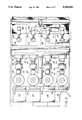
- FIG. 1is a side elevational view of a meltblowing system constructed according to the present invention.
- FIG. 2is a top plan view of the system shown in FIG. 1.
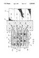
- FIG. 3is an enlarged sectional view of a portion of the system, with the cutting plane taken through line 3--3 of FIG. 2.
- FIG. 4is a sectional view of the gear pump shown in FIG. 3, the cutting plane indicated by line 4--4 in FIG. 3.
- FIG. 5is a sectional view of the die tip assembly and valve actuators of the system.
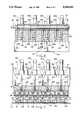
- FIG. 6is a sectional view of the die assembly shown in FIG. 3, with the cutting plane taken through line 6--6 thereof.
- FIG. 7is a simplified front elevational view of the die assembly from the perspective indicated by line 7--7 of FIG. 1.
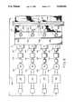
- FIG. 8is a schematic of the system, conceptually illustrating the feed back control of the system.
- FIG. 9is an alternate embodiment of the pumping assembly for the meltblowing system.
- the meltblowing system 10 constructed according to the present inventioncomprises a plurality of meltblown units, each of which includes die assembly 11, a pump assembly 12, a pump manifold 13, a drive shaft 14, an electric motor 16, motor controls 17, and a sensor assembly 18.
- the drive shaft 14may also include an electromagnetic clutch 15 and coupling 26.
- Hot air through lines 20, each of which may include an in-line heater 21,is delivered to opposite sides of the die assembly 11 and a revolving collector 19 is positioned below the die assembly 11 for receiving the meltblown fibers.
- pump 12Ais driven by motor 16A through shaft 14A.
- the pump 12Afeeds polymer melt to a longitudinal portion of die assembly 11 designated 11A (as described in detail below).
- the present inventionis described with reference to four units, the invention contemplates a plurality of units ranging from 2 to 100 preferably 4 to 80. most preferably 4 to 50.
- FIGS. 1, 3, 4, and 5depict only one of the meltblowing units or component thereof of the system and are described without reference to the letters (i.e., A-D). It should be understood, however, that each meltblowing unit has components corresponding to those depicted in FIGS. 1, 3, 4, and 5, unless otherwise indicated.
- the meltblowing system of the present inventionoperates as follows: polymer melt is delivered to the apparatus through line 23 into manifold 22.
- the manifold 22contains passages (described in detail below) which conduct the polymer melt to each of the pump assemblies 12A-12D, and from there to the separate die assemblies 11A-11D where the melt is extruded as a plurality of side-by-side filaments 24.
- Converging hot air delivered to the die via air conduits 20contacts the extruded filaments 24 and stretches them into microsized filaments or fibers.
- These filaments or fiberscollect on the collection surface 19 in a random manner forming a nonwoven web 25.
- the terms "filaments” and “fibers” as used hereinare interchangeable.
- the webalthough integral in appearance, consists of longitudinal strips 25A-25D, which are respectively formed by units 11A-11D.
- the side-by-side strips 25A-25Dare monitored by scanner 18 which measures a physical property of each strip such as thickness or basis weight.
- the monitor 18sends a signal to the controls 17A-17D, respectively, which in turn alter the operation of the variable speed electric motors 16A-16D, respectively, to increase or decrease the polymer throughput thereby maintaining uniformity of the selected property within each strip and/or across the width of the web 25.
- the die assembly 11comprises an elongate die body 27, a die tip assembly 28 connected to the bottom (i.e. mounting surface) of the die body 27, and a plurality of valve assemblies 29, one for each die assembly unit 11A-11D as described below.
- the die body and die tip components, as well as other parts of the system exposed to the high meltblowing temperaturesmay be machined from steel or steel alloys.
- the die body 27has formed therein intersecting polymer flow passages 30 and 31 for each unit. Passage 30 is aligned with a polymer flow passage in the pump manifold 13 (as described below) and passage 31 extends vertically in body 27, exiting at the underside of the die body 27 and serves as the outlet passage for the die body 27.
- An insert 32is mounted in recess 36 surrounding outlet passage 31. The exposed outer end of the insert 32 is spaced from the bottom of the recess 36 to provide an annular sealing surface 37 which engages a seal surface of the die assembly 28.
- the insert 32has formed therein a port 33, surrounded by annular valve seat 34 and cylindrical surface 35.
- the manifolds and die body 27may be provided with electric heaters (not shown) to heat and maintain the polymer passing therethrough at the desired temperatures.
- the die tip assembly 28is made up of three parts: (1) a transfer plate 38, (2) a die tip 39, and (3) air plates 41 and 42.
- the transfer plate 38may be bolted to the underside of the die tip 39 and this assembly bolted to the mounting surface of the die body 27 by bolts 43.
- the transfer plate 38extends substantially the entire length of the die body 27 (see FIG. 7) and has formed therein a polymer passage 44 for each of the meltblowing units 11A-11D.
- the flow passage 44exits into a semicircular groove formed in the underside of the transfer plate 38, which in combination with a similar groove formed in the underside of the die tip 39 defines an elongate header channel or chamber 46.
- the die tip 39has formed therein a nose section 47 of triangular cross section which is flanked by elongate flanges 48 and 49.
- the nose section 47terminates in an apex 50, through which are drilled a plurality of orifices 51 (see also 51A-51D in FIG. 7).
- Channel 53interconnects chamber 46 with the orifices 51.
- the orifices 51are aligned along the apex 50 to form a line therealong. It is preferred that the orifices 51 are equally spaced along the length of apex 50 as illustrated in FIG. 7 so that an integral single web 25 is formed on collector 19.
- the assembly of the transfer plate 38 with die tip 39 bolted theretois mounted to the underside of die body 27 by bolts 43 passing through flanges 48 and 49 and transfer plate 38.
- Annular seal surface 37engages the underside of the transfer plate 38 and, aided by an O-ring, provides a fluid seal therewith.
- the air plates 41 and 42are mounted on side plates 54 and 55, which in turn are secured to die body 27.
- the air plates 41 and 42may also include mounting blocks 56 and 57 which are adjustable thereby permitting the adjustment of the setback and air gap settings.
- Adjustment screws 58 and 59permit the adjustment of the setback and adjustment screws 60 and 61 permit the adjustment of the air gap.
- each air plate 41 and 42is tapered and in combination with the flanking surfaces of the triangular nose section 47 define converging air passage 62 and 63.
- the spacing between the confronting surfacesis referred to as air gap.
- Air passages 64 and 65 upstream of air passages 62 and 63, respectively,are defined by the configuration of the die tip 39, the transfer plate 38, blocks 56 and 57, die body 27 and side plates 54 and 55 as illustrated in FIG. 5.
- the air line 20connects to a mid-section of each air plate 54 and 55.
- Polymer flow through each die assembly unitis via passages 30 and 31 of the die body 27, through insert 32, through passage 44 of transfer plate, into chamber 46, through channel 53 and, finally, through orifices 51; whereas, air from the inlet pipes 20 flows through passages 64 and 62 on one side of the orifices and passages 65 and 63 on the other side, exiting as converging air sheets at apex 50 on opposite sides of tne extruded filaments 24.
- the parallel flow through the meltblowing units 11A-11Dis illustrated in FIG. 7.
- each meltblowing unit 11A-11Dwith a shut off valve assembly 29 shown in detail in FIG. 5.
- the valve assembly 29 for each unitincludes a stem 71 positioned concentrically in passage 31 and operatively connected to a valve actuator 69.
- the valve actuator for each unitcomprises a piston assembly 70, and a pneumatic control valve 74.
- the valve stem 71extends through a suitable packing assembly 76 into passage 31 terminating at valve tip 77.
- a piston 72 mounted in housing 75divides tne interior thereof into upper chamber 75a and lower chamber 75b.
- the piston 72is movable within housing 75 between an open position wherein the valve tip 77 is positioned above the valve seat 34 of insert member 32 and a closed position wherein the tip 77 seats on surface 34 thereby shutting off the flow of polymer through port 33.
- the valveis moved between the open and closed positions by control valve 74 which may be a solenoid, four-way, two position valve.
- Electric controls 78activates and deactivates the solenoid of the control valve 74.
- the solenoidis energized causing air to flow from control valve 74 through line 79 to chamber 75b while air exhausts from chamber 75a through line 80.
- the piston 72 and stem 71move upwardly opening port 33. Upward movement of the piston 72 is limited by adjustment rod 81.
- control valve 74In the normal deactivated position of the actuator 69, the solenoid of control valve 74 is de-energized causing air to flow through line 80 into the chamber 75a while air exhausts from the chamber 75b through line 79.
- Spring 82biases the piston 72 in the closed position with tip 77 in contact with valve seat 34.
- valve actuators 69The construction and operation of the valve actuators 69 are described in more detail in co-pending U.S. application Ser. No. 599,006, filed on Oct. 17, 1990, (now U.S. Pat. No. 5,145,689), the disclosure of which is incorporated herein by references.
- the hot air delivered to opposite sides of the die assembly 11 by lines 20may include an in-line electric air heater 21 (see FIG. 1) which may be of the same construction as described in said co-pending application U.S. application Ser. No. 599,006 (U.S. Pat. No. 5,145,689).
- the die body 27, transfer plate 38, and die tip 39, as well as, the air plates 41 and 42are of the same general length, traversing the full length of the row of orifices 51.
- the die body 27, while being of unitary constructionmay be viewed as separate side-by-side sections 27A-27D provided with flow passages 30A-30D (not shown in FIG. 7) and 31A-31D, inserts 32A-32D, and valve assemblies 29A-29D (including actuators 69A-69D).
- the die tip assembly 28includes end-to-end chambers 46A-46D which are, respectively, aligned with die body sections 27A-27D.
- the polymer extruded through orifices (e.g. 51A) of one die assembly section (e.g., 28A)is from chamber (e.g., 46A) and is separate from the polymer extruded through the orifices (e.g., 51B-51D).
- chambere.g., 46A
- the orifice spacing across the die lengthis preferably uniform so that the web produced thereby is uniform.
- the air flowis through two main passages which converge on opposite sides of the nose piece 47 as has been described above in relation to FIG. 5.
- the air passagesare not divided into units but extend substantially the entire length of the die.
- the inlet polymer flow passages 30 of each body section 27is fed by pump 12.
- the polymer flow to and from the pump 12 of each unitis provided by passages formed in the header manifold 22 and pump manifold 13.
- Polymeris delivered to a passage 83 in header manifold 22 which distributes the flow to a plurality of flow passages 84 of the header manifold 22.
- Manifold 13has formed therein a pump suction passage 86 which registers with header manifold passage 84 and the inlet of pump 12.
- a pump outlet passage 87extends from the outlet of the pump 12 to register with inlet passage 30 of die body 27.
- polymer flow into the header manifold 22is from line 23 and distributed header passages 83 to passages 84A-84D.
- Polymeris fed to each pump through passages 86A-86D, respectively, and discharged from pump 12A-12D (see FIG. 2) through passages 87A-87D, respectively, to die body inlet passages 30A-30D (not seen in FIG. 6) and outlet passage 31A-31D, respectively.
- the header passages 83may be provided with a porous filter 90.
- the pump 12 of each meltblowing unitmay be any positive displacement pump which provides output rate proportional to drive shaft rotation rate.
- the preferred positive displacement pumpis a gear pump which comprises a driven gear 88 keyed to shaft 14, and idler gear 89.
- the gears 88 and 89are mounted in a suitable housing 91 having endplates 92 and 93.
- the housing 91defines chamber 94 in which the gears 88 and 89 are mounted.
- Manifold passages 86 and 87communicate with chamber 94 on opposite sides of the meshing gears through ports 95 and 99, respectively.
- gear 89is driven in a clockwise direction thereby pumping polymer entering port 95 from passage 86 around the periphery of the gears and out through port 99 into passage 87.
- Conventional packing and bearingsmay be employed in the gear pump.
- the drive shaft 14is driven by a variable speed motor 16 through gear box 96.
- the drive shaft 14may also include a coupling 26 and electromagnetic clutch 15.
- the clutch 15is a safety device to prevent damage to the motor if the pump 12 fails.
- the output shaft 14extends through the gear box 96 terminating in pump speed sensor gear 97. It is preferred that the electric motor 16 be variable speed and have an rpm output between 1500 to 2000, and that the gear box 96 have a gear reduction ratio of 20 to 1.
- a sensor probe 98such as a proximity switch or digital pulse encoders is used to detect the rpm of shaft 14. These devices are commercially available.
- the electric motor 16may be one of many designs and constructions. An electric motor that has proven successful in the apparatus of the present invention is manufactured by Baldor. This 1725 rpm motor with gear reducer box provides and output range of 0 to 104 rpm.
- an important part of the present inventionis the provisions of sensing means 18 for monitoring a property of the web 25 as it is collected on collector 19.
- an on-line thickness gaugemay be provided, such as a Model 6100 Series Basic Scanning System, marketed by NDC Systems, it is preferred that the monitor be a basis weight monitor such as a Gamma Backscatter Probe marketed by NDC Systems.
- the sensing means 18includes a sensing probe 101 mounted on a track 102 which traverses the width of the web 2b.
- the sensing probe 101moves along the track scanning the web 25 and senses a property thereof such as the web thickness or the basis weight of the web 25.
- FIG. 8illustrates in schematic the concept of operation of the various meltblowing units 11A-11D in response to a web property sensed by probe 101.
- the probeis a Gamma Backscatter Probe (Compton Photon Backscatter). Photons from a very small radioactive isotope are back scattered in direct proportion to the mass (i.e., weight per unit area or basis weight) of the web in front of the probe.
- a scintillation detector and electronicsconvert the photon count to an electric signal which is transmitted through electric conductor 103 to a computer programmed to send signals to each of the pump controls 17A-17D corresponding to the sensed signal for strips 25A-25D, respectively of the web.
- a signalis received and transmitted to pump control 17A.
- the computermay also integrate the average of the signals to represent the average basis weight across web strip 25A.
- the probe 101in a like manner sends signals to pump controls 17B, etc.
- the controlsare calibrated so that if the monitored property (e.g., basis weight) varies from a predetermined value, the signal to the electric motor of each meltblowing unit is adjusted to change the rpm and change the output of the gear pump for that unit.
- the sensor 98senses the rpm of the drive shaft 14 via sensor gear 97 and provides a signal to the controls for controlling the motor rpm, thereby automatically setting the correct pump speed and polymer flow rate for achieving the desired web properties.
- Probes, sensors, computers and controls for performing the functions describedare available from a variety of companies including NDC Systems. It should be noted, however, that while NDC Systems advertise industrial application for these systems as including cast or extruded sheet and film, blown film, rubber and vinyl coatings, composites, pipe and tubing, paper and film, textiles and nonwovens, the sensing systems have never been used as described and claimed in the present invention: to sense a property in a relatively narrow longitudinal strip of a nonwoven web and alter the system output in response thereto.
- the volume between the valve seat and the orifice dischargebe 0.3 cc per inch of die length, preferably between 0.2 to 0.3 cc per inch of die.
- meltblowing system of the present inventionhas been described to somewhat simplified design for clarity of description.
- many of the components illustrated as unitary bodies, such as die body and manifolds,may be made in two or more parts to facilitate assembly.
- the systemmay include hoods or housings for safety and operation protection.
- the components of the meltblowing system 10are assembled as illustrated in FIGS. 1, 2, and 8.
- the valve actuators 69A-69Dare adjusted to provide the desired stroke (e.g., 0.100 to 0.750 inches).
- the collector 19is positioned within about 5 to 15 inches below the die outlet and the probe 101 is positioned above the collector 19, in accordance with the manufacture's specification. It is preferred to locate the probe 4 to 24 inches downstream of the area in which the fibers are first collected on the collector 19, although this is not critical.
- the computeris adjusted to provide a control of the web property monitored (e.g., thickness or basis weight). In the case of basis weight control, typical values are 5 to 100 grams/square meter.
- the system 10may be fed by an extruder in a conventional hookup or it may be fed by a polymer delivery system disclosed in U.S. patent application Ser. No. 447,930, filed Dec. 8, 1989, now U.S. Pat. No. 5,061,170.
- the typical meltblowing web forming resinsinclude a wide range of polyolefins such as propylene and ethylene homopolymers and copolymers.
- Specific thermoplasticsincludes ethylene acrylic copolymers, nylon, polyamides, polyesters, polystyrene, poly(methyl methacrylate), polytrifluoro-chloroethylene, polyurethanes, polycarbonates, silicone sulfide, and poly(ethylene terephthalate), pitch, and blends of the above
- the preferred resinis polypropylene. The above list is not intended to be limiting, as new and improved meltblowing thermoplastic resins continue to be developed.
- the operating temperature of the meltblowing systemwill of course depend on the resin employed, but for PP (MFR of 800), they may be as follows:
- the fibers 24collect on the collector 19 forming web 25 which passes under probe 101.
- the rate of the movement of the webtypically is 10 to 300 feet per minute.
- the probe 101 moving along track 102scans each strip 25A-25D of the full width of "60" web 25 in about 3-5 seconds. Variations of the basis weight of a web strip as detected and if outside the control range (+0.5%-1%), the speed of the motor 16 and gear pump 12 for that strip is changed in response thereto to bring the basis weight in conformity with the control value.
- the basis weight control levelis 10 grams/square meter and a basis weight for web strip 25B is measured at 9.87 grams/m sq.
- the rpm of motor 16B and hence pump 12Bis increased to increase the polymer throughput of meltblowing unit 11B. This increases the amount of fibers laid down to form strip 25B and increases the basis weight.
- valve assemblies 29A-29Dare actuated closing the ports 33 of each meltblowing unit 11, thereby preventing after flow.
- the valve actuators 69 for the unit which contains the plugged orificemay be manually operated.
- the valve stem 71 passing into and in close conformity with the cylindrical surface 35 of insert 32acts as a plunger causing a pressure or volume pulse or surge to flow through the downstream orifices 51 which removes any plugging or residue in or at the discharge of the orifices 51.
- a meltblowing system 10having components as described above for the best mode and depicted in the Drawings was built.
- the systemhad four units and employed an extruder to provide the polymer melt.
- the systemproduced a web of 6 inches wide and a monitor (NDC Gamma Backscatter Probe) was used to detect the basis weight of the web, controlled at 15 GSM.
- the variation of the basis weight across the width of the webwas +0.95%, which represents a high quality web.
- the diecomprises a plurality of transverse meltblowing units positioned side-by-side, with each unit being provided with separate pump means and polymer flow passages.
- the pump meansare separately controlled to make the positive displacement pumps responsive to changes in a web property such as thickness or basis weight.
- the die assembly 11is also constructed to function as a plurality of transverse side-by-side meltblowing units as described above and are also provided by separate gear pumps 12.
- the gear pumps 12are driven by the same shaft or at the same rate so that the output of each meltblowing unit is precisely the same.
- This constructionensures that the polymer rate delivered to each unit and extruded therefrom is exactly the same as the polymer rate in the other units. This produces a uniform polymer output across the width producing uniform webs which of the die 11 becomes important for long dies that produce wide webs.
- each meltblowing unit 11A-11Dhave a length not greater than 3 inches, and preferably between 0.5 to 2 inches.
- Each unitis also provided with from 20 to 30 orifices 51 per inch as described above.
- the die assemblies 11A-11D and air delivery system as well as the valve assemblies 29A-29Dmay be the same in this alternate embodiment as those illustrated in FIGS. 1 and 5 and described above.
- the only difference between this embodiment with respect to the die assembly 11is the flow passages from the gear pumps 12.
- the alternate embodimentincludes a plurality of gear pumps arranged in stacked relationship and illustrated as 110A through 110D.
- Each of the gear pumpsincludes a driven gear 111A-111D, which meshes with idler gear 112A-112D, respectively.
- the driven gears 111A-111Dare mounted on drive shaft 14 which is driven by a motor 16 which may be oriented as illustrated in FIG. 1.
- all gear pumps 110A-110Dare driven by shaft 14.
- Each of the gear pumps 110A-110Dhas a polymer feed passage 113A-113D, respectively, and an outlet flow passage 114A-114D, respectively.
- Each of the gear pump outlet flow passages 114A-114Dregister with flow passages 116A-116D, respectively, formed in the die body 27.
- Flow passages 116A-116Ddeliver polymer to the flow passage 31A-31D, respectively, in the die body 27 which may be the same as described previously.
- the polymeris delivered to each pump 110A-110D through passages 113A-113D through manifolds 115 and 116.
- the embodiment illustrated in FIG. 9employs parallel flow of polymer to each gear pump 110A-110D and from there to each meltblowing unit 11A-11D.
- the main advantage of this alternate embodiment over the prior art systemsis that the positive displacement pumps, being of the same size and driven by one shaft 14 at the same rpm, ensures that the flow to each unit is the same so that the web produced by the plurality of relatively short units will be uniform.
- the prior art diesrequired a coat hanger balancing die to deliver polymer from a single polymer inlet to the full width of the die.
- This prior art constructionworks well for short dies but for long dies, the polymer friction losses being different from the center of the die to the outer part and orifices of the die inherently produces uneven flow and web non-uniformities.
- the coat hanger dieis complex in configuration requiring expensive machining.
- each meltblowing unitIn order to achieve the uniform output of each meltblowing unit, it is only necessary that the pump outputs be separate and at the same rate.
- the suction lines of the pumpsmay be common.
- a gear pump manufactured by Zenith Nicholswhich is described as a 4 Stream, 6 Gear, Type H Pump which includes two separate pumping units. Each unit comprises a driven gear and two identical idler gears, thus functioning as two pumps with intermixing flow at the suction but separate flow at the discharge. Since the driven gear drives the two idler gears meshed therewith at the same rpm, the output of each is the same. This assembly thus produces four outlets with six gears, two of which are driven by the same shaft. Assemblies of one gear for driving four and eight idler gears are also available.
- the polymer usable in this alternative design and the operationmay be as described previously except that no sensors are provided so that the output may be not varied across the length of the die.
Landscapes
- Engineering & Computer Science (AREA)
- Mechanical Engineering (AREA)
- Textile Engineering (AREA)
- Spinning Methods And Devices For Manufacturing Artificial Fibers (AREA)
- Nonwoven Fabrics (AREA)
- Extrusion Moulding Of Plastics Or The Like (AREA)
- Preparation Of Compounds By Using Micro-Organisms (AREA)
Abstract
Description
______________________________________ MOST PRE- PREFERRED BROAD FERRED RANGE RANGE RANGE BEST MODE) ______________________________________ Length of Die (inches) 1-150 4-150 6-150 Number of Units 2-100 4-80 4-50 Length of Units 0.5-12.0 1-8 1.5-3.0 (inches) Orifice Diameter 0.010-0.080 0.010-0.040 0.015-0.030 (inches) Orifices/inch 10-50 15-40 20-30 Gear Pump Capacity 1-20 2-12 4-10 (for each Unit lbs/hr) Polymer Flow Rate 1-20 2-12 4-10 (per unit lbs/hr) Polymer Flow Rate 0.8-3 0.9-2 1.0-1.6 (per orifice grams/hol/min) Air Gap (inches) .010-.200 .020-.150 .040-.120 Set Back (inches) .010-.200 .020-.150 .040-.120 Air Capacity 5-30 10-25 15-20 (SCFM/inch) ______________________________________
Claims (19)
Priority Applications (10)
| Application Number | Priority Date | Filing Date | Title |
|---|---|---|---|
| US07/757,848US5236641A (en) | 1991-09-11 | 1991-09-11 | Metering meltblowing system |
| CA002117175ACA2117175C (en) | 1991-09-11 | 1992-09-11 | Metering meltblowing system |
| AU26593/92AAU659587B2 (en) | 1991-09-11 | 1992-09-11 | Metering meltblowing system |
| RU94044334/26ARU94044334A (en) | 1991-09-11 | 1992-09-11 | Monitoring and measurement system in the process of extrusion of polymer fibers with their blowing off |
| EP92920301AEP0604545B1 (en) | 1991-09-11 | 1992-09-11 | Metering meltblowing system |
| JP5505519AJP2892157B2 (en) | 1991-09-11 | 1992-09-11 | Quantitative melting blowout device |
| KR1019940700773AKR0129863B1 (en) | 1991-09-11 | 1992-09-11 | Metering meltblowing system |
| DE69231568TDE69231568T2 (en) | 1991-09-11 | 1992-09-11 | CONTROL IN A MELT BLOW PROCESS |
| KR1019940700773AKR940702566A (en) | 1991-09-11 | 1992-09-11 | METERING MELTBLOWING SYSTEM |
| PCT/US1992/007727WO1993005212A2 (en) | 1991-09-11 | 1992-09-11 | Metering meltblowing system |
Applications Claiming Priority (1)
| Application Number | Priority Date | Filing Date | Title |
|---|---|---|---|
| US07/757,848US5236641A (en) | 1991-09-11 | 1991-09-11 | Metering meltblowing system |
Publications (1)
| Publication Number | Publication Date |
|---|---|
| US5236641Atrue US5236641A (en) | 1993-08-17 |
Family
ID=25049467
Family Applications (1)
| Application Number | Title | Priority Date | Filing Date |
|---|---|---|---|
| US07/757,848Expired - LifetimeUS5236641A (en) | 1991-09-11 | 1991-09-11 | Metering meltblowing system |
Country Status (9)
| Country | Link |
|---|---|
| US (1) | US5236641A (en) |
| EP (1) | EP0604545B1 (en) |
| JP (1) | JP2892157B2 (en) |
| KR (2) | KR940702566A (en) |
| AU (1) | AU659587B2 (en) |
| CA (1) | CA2117175C (en) |
| DE (1) | DE69231568T2 (en) |
| RU (1) | RU94044334A (en) |
| WO (1) | WO1993005212A2 (en) |
Cited By (50)
| Publication number | Priority date | Publication date | Assignee | Title |
|---|---|---|---|---|
| US5354378A (en)* | 1992-07-08 | 1994-10-11 | Nordson Corporation | Slot nozzle apparatus for applying coatings to bottles |
| US5409642A (en)* | 1993-10-06 | 1995-04-25 | Exxon Chemical Patents Inc. | Melt blowing of tubular filters |
| US5409733A (en)* | 1992-07-08 | 1995-04-25 | Nordson Corporation | Apparatus and methods for applying conformal coatings to electronic circuit boards |
| US5418009A (en)* | 1992-07-08 | 1995-05-23 | Nordson Corporation | Apparatus and methods for intermittently applying discrete adhesive coatings |
| US5421921A (en)* | 1992-07-08 | 1995-06-06 | Nordson Corporation | Segmented slot die for air spray of fibers |
| US5423935A (en)* | 1992-07-08 | 1995-06-13 | Nordson Corporation | Methods for applying discrete coatings |
| US5429840A (en)* | 1992-07-08 | 1995-07-04 | Nordson Corporation | Apparatus and methods for applying discrete foam coatings |
| US5458291A (en)* | 1994-03-16 | 1995-10-17 | Nordson Corporation | Fluid applicator with a noncontacting die set |
| US5523146A (en)* | 1993-01-08 | 1996-06-04 | Poly-Bond, Inc. | Composite with discontinuous adhesive structure |
| US5589249A (en)* | 1993-01-08 | 1996-12-31 | Poly-Bond, Inc. | Medical composite with discontinuous adhesive structure |
| US5618566A (en)* | 1995-04-26 | 1997-04-08 | Exxon Chemical Patents, Inc. | Modular meltblowing die |
| US5648041A (en)* | 1995-05-05 | 1997-07-15 | Conoco Inc. | Process and apparatus for collecting fibers blow spun from solvated mesophase pitch |
| US5728219A (en)* | 1995-09-22 | 1998-03-17 | J&M Laboratories, Inc. | Modular die for applying adhesives |
| US5740963A (en)* | 1997-01-07 | 1998-04-21 | Nordson Corporation | Self-sealing slot nozzle die |
| US5863485A (en)* | 1996-03-22 | 1999-01-26 | Groleau; Rodney J. | Injection molding machine employing a flow path gear pump and method of use |
| US5891482A (en)* | 1996-07-08 | 1999-04-06 | Aaf International | Melt blowing apparatus for producing a layered filter media web product |
| WO1999054055A1 (en) | 1998-04-20 | 1999-10-28 | Nordson Corporation | Segmented metering die for hot melt adhesives or other polymer melts |
| US6210141B1 (en) | 1998-02-10 | 2001-04-03 | Nordson Corporation | Modular die with quick change die tip or nozzle |
| US6220843B1 (en) | 1998-03-13 | 2001-04-24 | Nordson Corporation | Segmented die for applying hot melt adhesives or other polymer melts |
| US20020083895A1 (en)* | 2000-03-14 | 2002-07-04 | Nordson Corporation | Device and method for applying adhesive filaments to materials such as strands or flat substrates |
| US6419126B2 (en) | 2000-05-16 | 2002-07-16 | Nordson Corporation | Spreading device for spreading fluids, and device for delivering and applying fluid, especially adhesive |
| US20020092865A1 (en)* | 2000-10-20 | 2002-07-18 | Hiroyuki Takagi | Device and method for applying a liquid to sheet-shaped materials |
| US6422428B1 (en) | 1998-04-20 | 2002-07-23 | Nordson Corporation | Segmented applicator for hot melt adhesives or other thermoplastic materials |
| US6601741B2 (en) | 2001-11-28 | 2003-08-05 | Illinois Tool Works Inc. | Laminated distribution manifold plate system |
| US6607104B2 (en) | 2001-05-24 | 2003-08-19 | Illinois Tool Works Inc. | Metered output hot melt adhesive dispensing system with return isolation loop |
| US20030168180A1 (en)* | 2002-01-28 | 2003-09-11 | Nordson Corporation | Compact heated air manifolds for adhesive application |
| US20030236046A1 (en)* | 2002-06-20 | 2003-12-25 | 3M Innovative Properties Company | Nonwoven web die and nonwoven webs made therewith |
| US20030234464A1 (en)* | 2002-06-20 | 2003-12-25 | 3M Innovative Properties Company | Attenuating fluid manifold for meltblowing die |
| US20030234463A1 (en)* | 2002-06-20 | 2003-12-25 | 3M Innovative Properties Company | Meltblowing apparatus employing planetary gear metering pump |
| US6726465B2 (en)* | 1996-03-22 | 2004-04-27 | Rodney J. Groleau | Injection molding machine employing a flow path gear pump and method of use |
| US20050133971A1 (en)* | 2003-12-23 | 2005-06-23 | Haynes Bryan D. | Meltblown die having a reduced size |
| US20050242108A1 (en)* | 2004-04-30 | 2005-11-03 | Nordson Corporation | Liquid dispenser having individualized process air control |
| US20060141086A1 (en)* | 2004-12-23 | 2006-06-29 | Kimberly-Clark Worldwide, Inc. | Low turbulence die assembly for meltblowing apparatus |
| US20070062887A1 (en)* | 2005-09-20 | 2007-03-22 | Schwandt Brian W | Space optimized coalescer |
| US20070062886A1 (en)* | 2005-09-20 | 2007-03-22 | Rego Eric J | Reduced pressure drop coalescer |
| US20070107399A1 (en)* | 2005-11-14 | 2007-05-17 | Schwandt Brian W | Variable coalescer |
| US20070131235A1 (en)* | 2005-11-14 | 2007-06-14 | Janikowski Eric A | Method and apparatus for making filter element, including multi-characteristic filter element |
| US20090039564A1 (en)* | 2005-04-19 | 2009-02-12 | Polymer Group, Inc. | Process and apparatus for forming uniform nanofiber substrates |
| US20090065611A1 (en)* | 2006-01-06 | 2009-03-12 | Nordson Corporation | Liquid dispenser having individualized process air control |
| US20090126324A1 (en)* | 2007-11-15 | 2009-05-21 | Smith Guillermo A | Authorized Filter Servicing and Replacement |
| US7828869B1 (en) | 2005-09-20 | 2010-11-09 | Cummins Filtration Ip, Inc. | Space-effective filter element |
| US20140255531A1 (en)* | 2013-03-11 | 2014-09-11 | Toyo Tire & Rubber Co., Ltd. | Method of estimating life of gear pump and rubber extrusion apparatus |
| US9186695B2 (en) | 2010-04-01 | 2015-11-17 | B&H Manufacturing Company, Inc. | Extrusion application system |
| US20170276532A1 (en)* | 2014-08-27 | 2017-09-28 | Skf Lubrication Systems Germany Gmbh | Housing for a device for the metered distribution of a medium, and metering device for use in the housing |
| US20180065141A1 (en)* | 2016-09-08 | 2018-03-08 | Nordson Corporation | Applicator with at least one pump having an integrated drive |
| US20180105956A1 (en)* | 2016-10-18 | 2018-04-19 | Reifenhaeuser Gmbh & Co. Kg Maschinenfabrik | Method and apparatus for making a fiber fleece |
| CN109843449A (en)* | 2016-09-08 | 2019-06-04 | 诺信公司 | Long-distance metering station |
| US10695779B2 (en) | 2016-09-08 | 2020-06-30 | Nordson Corporation | Applicator having active backpressure control devices |
| US11447893B2 (en) | 2017-11-22 | 2022-09-20 | Extrusion Group, LLC | Meltblown die tip assembly and method |
| US11958308B1 (en) | 2023-05-31 | 2024-04-16 | G13 Innovation In Production Ltd | Thermal paper, and methods and systems for forming the same |
Families Citing this family (4)
| Publication number | Priority date | Publication date | Assignee | Title |
|---|---|---|---|---|
| JP5343591B2 (en)* | 2009-02-04 | 2013-11-13 | ブラザー工業株式会社 | Adhesive supply device |
| US9149959B2 (en) | 2010-10-22 | 2015-10-06 | Monosol Rx, Llc | Manufacturing of small film strips |
| KR101326506B1 (en)* | 2012-04-30 | 2013-11-08 | 현대자동차주식회사 | Manufacturing method of melt-blown fabric web having random and bulky caricteristics and manufacuring apparatus thereof |
| CN110241465B (en)* | 2018-12-24 | 2021-06-15 | 中芳特纤股份有限公司 | A PPTA spinning flow control system and control method |
Citations (5)
| Publication number | Priority date | Publication date | Assignee | Title |
|---|---|---|---|---|
| US4268235A (en)* | 1979-12-21 | 1981-05-19 | American Can Company | Apparatus for the manufacture of fibrous webs |
| US4708619A (en)* | 1985-02-27 | 1987-11-24 | Reifenhauser Gmbh & Co. Maschinenfabrik | Apparatus for spinning monofilaments |
| US4818463A (en)* | 1986-04-26 | 1989-04-04 | Buehning Peter G | Process for preparing non-woven webs |
| US4820142A (en)* | 1987-04-25 | 1989-04-11 | Reifenhauser Gmbh & Co. Maschinenfabrik | Apparatus for making a spun-filament fleece |
| US4983109A (en)* | 1988-01-14 | 1991-01-08 | Nordson Corporation | Spray head attachment for metering gear head |
Family Cites Families (4)
| Publication number | Priority date | Publication date | Assignee | Title |
|---|---|---|---|---|
| GB926799A (en)* | 1960-08-12 | 1963-05-22 | Ici Ltd | Melt spinning apparatus |
| DE1273174B (en)* | 1966-11-03 | 1968-07-18 | Vickers Zimmer Ag | Device for spinning threads, ribbons or strands from a melt or a solution made from higher linear polymers |
| US3782873A (en)* | 1968-09-20 | 1974-01-01 | Du Pont | Thickness control apparatus for polymeric film structures |
| US5145689A (en)* | 1990-10-17 | 1992-09-08 | Exxon Chemical Patents Inc. | Meltblowing die |
- 1991
- 1991-09-11USUS07/757,848patent/US5236641A/ennot_activeExpired - Lifetime
- 1992
- 1992-09-11RURU94044334/26Apatent/RU94044334A/enunknown
- 1992-09-11KRKR1019940700773Apatent/KR940702566A/enactiveGranted
- 1992-09-11JPJP5505519Apatent/JP2892157B2/ennot_activeExpired - Lifetime
- 1992-09-11KRKR1019940700773Apatent/KR0129863B1/ennot_activeExpired - Fee Related
- 1992-09-11EPEP92920301Apatent/EP0604545B1/ennot_activeExpired - Lifetime
- 1992-09-11CACA002117175Apatent/CA2117175C/ennot_activeExpired - Fee Related
- 1992-09-11WOPCT/US1992/007727patent/WO1993005212A2/enactiveIP Right Grant
- 1992-09-11DEDE69231568Tpatent/DE69231568T2/ennot_activeExpired - Fee Related
- 1992-09-11AUAU26593/92Apatent/AU659587B2/ennot_activeCeased
Patent Citations (5)
| Publication number | Priority date | Publication date | Assignee | Title |
|---|---|---|---|---|
| US4268235A (en)* | 1979-12-21 | 1981-05-19 | American Can Company | Apparatus for the manufacture of fibrous webs |
| US4708619A (en)* | 1985-02-27 | 1987-11-24 | Reifenhauser Gmbh & Co. Maschinenfabrik | Apparatus for spinning monofilaments |
| US4818463A (en)* | 1986-04-26 | 1989-04-04 | Buehning Peter G | Process for preparing non-woven webs |
| US4820142A (en)* | 1987-04-25 | 1989-04-11 | Reifenhauser Gmbh & Co. Maschinenfabrik | Apparatus for making a spun-filament fleece |
| US4983109A (en)* | 1988-01-14 | 1991-01-08 | Nordson Corporation | Spray head attachment for metering gear head |
Cited By (104)
| Publication number | Priority date | Publication date | Assignee | Title |
|---|---|---|---|---|
| US5683036A (en)* | 1992-07-08 | 1997-11-04 | Nordson Corporation | Apparatus for applying discrete coatings |
| US5409733A (en)* | 1992-07-08 | 1995-04-25 | Nordson Corporation | Apparatus and methods for applying conformal coatings to electronic circuit boards |
| US5418009A (en)* | 1992-07-08 | 1995-05-23 | Nordson Corporation | Apparatus and methods for intermittently applying discrete adhesive coatings |
| US5421921A (en)* | 1992-07-08 | 1995-06-06 | Nordson Corporation | Segmented slot die for air spray of fibers |
| US5423935A (en)* | 1992-07-08 | 1995-06-13 | Nordson Corporation | Methods for applying discrete coatings |
| US5429840A (en)* | 1992-07-08 | 1995-07-04 | Nordson Corporation | Apparatus and methods for applying discrete foam coatings |
| US5524828A (en)* | 1992-07-08 | 1996-06-11 | Nordson Corporation | Apparatus for applying discrete foam coatings |
| US5533675A (en)* | 1992-07-08 | 1996-07-09 | Nordson Corporation | Apparatus for applying discrete coatings |
| US5354378A (en)* | 1992-07-08 | 1994-10-11 | Nordson Corporation | Slot nozzle apparatus for applying coatings to bottles |
| US5685911A (en)* | 1992-07-08 | 1997-11-11 | Nordson Corporation | Apparatus for intermittently applying discrete adhesive coatings |
| US5523146A (en)* | 1993-01-08 | 1996-06-04 | Poly-Bond, Inc. | Composite with discontinuous adhesive structure |
| US5589249A (en)* | 1993-01-08 | 1996-12-31 | Poly-Bond, Inc. | Medical composite with discontinuous adhesive structure |
| US5705011A (en)* | 1993-01-08 | 1998-01-06 | Poly-Bond, Inc. | Method of making composite with discontinuous adhesive structure |
| US5409642A (en)* | 1993-10-06 | 1995-04-25 | Exxon Chemical Patents Inc. | Melt blowing of tubular filters |
| US5458291A (en)* | 1994-03-16 | 1995-10-17 | Nordson Corporation | Fluid applicator with a noncontacting die set |
| US5636790A (en)* | 1994-03-16 | 1997-06-10 | Nordson Corporation | Fluid applicator |
| US5618566A (en)* | 1995-04-26 | 1997-04-08 | Exxon Chemical Patents, Inc. | Modular meltblowing die |
| US5648041A (en)* | 1995-05-05 | 1997-07-15 | Conoco Inc. | Process and apparatus for collecting fibers blow spun from solvated mesophase pitch |
| US5728219A (en)* | 1995-09-22 | 1998-03-17 | J&M Laboratories, Inc. | Modular die for applying adhesives |
| US5863485A (en)* | 1996-03-22 | 1999-01-26 | Groleau; Rodney J. | Injection molding machine employing a flow path gear pump and method of use |
| US6726465B2 (en)* | 1996-03-22 | 2004-04-27 | Rodney J. Groleau | Injection molding machine employing a flow path gear pump and method of use |
| US5891482A (en)* | 1996-07-08 | 1999-04-06 | Aaf International | Melt blowing apparatus for producing a layered filter media web product |
| US5976209A (en)* | 1996-07-08 | 1999-11-02 | Aaf International | Melt blown product formed as a fibrous layered web of filter media |
| US5976427A (en)* | 1996-07-08 | 1999-11-02 | Aaf International | Melt blowing method for forming layered webs of filter media |
| EP0822282A3 (en)* | 1996-07-08 | 2000-11-22 | Aaf International | Melt blowing method for forming a fibrous layered web of filter media, melt blowing apparatus and a layered filter media web product |
| US5740963A (en)* | 1997-01-07 | 1998-04-21 | Nordson Corporation | Self-sealing slot nozzle die |
| US6210141B1 (en) | 1998-02-10 | 2001-04-03 | Nordson Corporation | Modular die with quick change die tip or nozzle |
| US6220843B1 (en) | 1998-03-13 | 2001-04-24 | Nordson Corporation | Segmented die for applying hot melt adhesives or other polymer melts |
| USRE39399E1 (en) | 1998-03-13 | 2006-11-14 | Nordson Corporation | Segmented die for applying hot melt adhesives or other polymer melts |
| US6296463B1 (en) | 1998-04-20 | 2001-10-02 | Nordson Corporation | Segmented metering die for hot melt adhesives or other polymer melts |
| US6422428B1 (en) | 1998-04-20 | 2002-07-23 | Nordson Corporation | Segmented applicator for hot melt adhesives or other thermoplastic materials |
| WO1999054055A1 (en) | 1998-04-20 | 1999-10-28 | Nordson Corporation | Segmented metering die for hot melt adhesives or other polymer melts |
| US20020083895A1 (en)* | 2000-03-14 | 2002-07-04 | Nordson Corporation | Device and method for applying adhesive filaments to materials such as strands or flat substrates |
| US6419126B2 (en) | 2000-05-16 | 2002-07-16 | Nordson Corporation | Spreading device for spreading fluids, and device for delivering and applying fluid, especially adhesive |
| US20020092865A1 (en)* | 2000-10-20 | 2002-07-18 | Hiroyuki Takagi | Device and method for applying a liquid to sheet-shaped materials |
| US6607104B2 (en) | 2001-05-24 | 2003-08-19 | Illinois Tool Works Inc. | Metered output hot melt adhesive dispensing system with return isolation loop |
| US6601741B2 (en) | 2001-11-28 | 2003-08-05 | Illinois Tool Works Inc. | Laminated distribution manifold plate system |
| US8196778B2 (en) | 2002-01-28 | 2012-06-12 | Nordson Corporation | Process air-assisted dispensing systems |
| US20070215718A1 (en)* | 2002-01-28 | 2007-09-20 | Nordson Corporation | Compact heated air manifolds for adhesive application |
| US8453880B2 (en) | 2002-01-28 | 2013-06-04 | Nordson Corporation | Process air-assisted dispensing systems and methods |
| US7614525B2 (en) | 2002-01-28 | 2009-11-10 | Nordson Corporation | Compact heated air manifolds for adhesive application |
| US7617951B2 (en) | 2002-01-28 | 2009-11-17 | Nordson Corporation | Compact heated air manifolds for adhesive application |
| US20030168180A1 (en)* | 2002-01-28 | 2003-09-11 | Nordson Corporation | Compact heated air manifolds for adhesive application |
| US20100018996A1 (en)* | 2002-01-28 | 2010-01-28 | Nordson Corporation | Process air-assisted dispensing systems |
| US6824733B2 (en) | 2002-06-20 | 2004-11-30 | 3M Innovative Properties Company | Meltblowing apparatus employing planetary gear metering pump |
| US20030234464A1 (en)* | 2002-06-20 | 2003-12-25 | 3M Innovative Properties Company | Attenuating fluid manifold for meltblowing die |
| US7690902B2 (en) | 2002-06-20 | 2010-04-06 | 3M Innovative Properties Company | Nonwoven web forming apparatus |
| US20050054254A1 (en)* | 2002-06-20 | 2005-03-10 | 3M Innovative Properties Company | Method for making a nonwoven web |
| US6861025B2 (en) | 2002-06-20 | 2005-03-01 | 3M Innovative Properties Company | Attenuating fluid manifold for meltblowing die |
| US6846450B2 (en) | 2002-06-20 | 2005-01-25 | 3M Innovative Properties Company | Method for making a nonwoven web |
| US20070237849A1 (en)* | 2002-06-20 | 2007-10-11 | 3M Innovative Properties Company | Nonwoven web forming apparatus |
| US20030236046A1 (en)* | 2002-06-20 | 2003-12-25 | 3M Innovative Properties Company | Nonwoven web die and nonwoven webs made therewith |
| WO2004001105A1 (en)* | 2002-06-20 | 2003-12-31 | 3M Innovative Properties Company | Meltblowing apparatus employing planetary gear metering pump |
| CN100347349C (en)* | 2002-06-20 | 2007-11-07 | 3M创新有限公司 | Melt blown apparatus and method for producing fiber web using the apparatus |
| US20030234463A1 (en)* | 2002-06-20 | 2003-12-25 | 3M Innovative Properties Company | Meltblowing apparatus employing planetary gear metering pump |
| US20050133971A1 (en)* | 2003-12-23 | 2005-06-23 | Haynes Bryan D. | Meltblown die having a reduced size |
| US6972104B2 (en) | 2003-12-23 | 2005-12-06 | Kimberly-Clark Worldwide, Inc. | Meltblown die having a reduced size |
| US10155241B2 (en) | 2004-04-30 | 2018-12-18 | Nordson Corporation | Liquid dispenser having individualized process air control |
| US20050242108A1 (en)* | 2004-04-30 | 2005-11-03 | Nordson Corporation | Liquid dispenser having individualized process air control |
| US7316552B2 (en) | 2004-12-23 | 2008-01-08 | Kimberly-Clark Worldwide, Inc. | Low turbulence die assembly for meltblowing apparatus |
| US20060141086A1 (en)* | 2004-12-23 | 2006-06-29 | Kimberly-Clark Worldwide, Inc. | Low turbulence die assembly for meltblowing apparatus |
| US7628941B2 (en) | 2005-04-19 | 2009-12-08 | Polymer Group, Inc. | Process and apparatus for forming uniform nanofiber substrates |
| US20090039564A1 (en)* | 2005-04-19 | 2009-02-12 | Polymer Group, Inc. | Process and apparatus for forming uniform nanofiber substrates |
| US8545707B2 (en) | 2005-09-20 | 2013-10-01 | Cummins Filtration Ip, Inc. | Reduced pressure drop coalescer |
| US20070062887A1 (en)* | 2005-09-20 | 2007-03-22 | Schwandt Brian W | Space optimized coalescer |
| US20070062886A1 (en)* | 2005-09-20 | 2007-03-22 | Rego Eric J | Reduced pressure drop coalescer |
| US8114183B2 (en) | 2005-09-20 | 2012-02-14 | Cummins Filtration Ip Inc. | Space optimized coalescer |
| US7828869B1 (en) | 2005-09-20 | 2010-11-09 | Cummins Filtration Ip, Inc. | Space-effective filter element |
| US20110094382A1 (en)* | 2005-09-20 | 2011-04-28 | Cummins Filtration Ip, Inc. | Reduced pressure drop coalescer |
| US20070107399A1 (en)* | 2005-11-14 | 2007-05-17 | Schwandt Brian W | Variable coalescer |
| US20070131235A1 (en)* | 2005-11-14 | 2007-06-14 | Janikowski Eric A | Method and apparatus for making filter element, including multi-characteristic filter element |
| US7674425B2 (en) | 2005-11-14 | 2010-03-09 | Fleetguard, Inc. | Variable coalescer |
| US8231752B2 (en) | 2005-11-14 | 2012-07-31 | Cummins Filtration Ip Inc. | Method and apparatus for making filter element, including multi-characteristic filter element |
| US20090065611A1 (en)* | 2006-01-06 | 2009-03-12 | Nordson Corporation | Liquid dispenser having individualized process air control |
| US9914147B2 (en) | 2006-01-06 | 2018-03-13 | Nordson Corporation | Liquid dispenser having individualized process air control |
| US7959714B2 (en) | 2007-11-15 | 2011-06-14 | Cummins Filtration Ip, Inc. | Authorized filter servicing and replacement |
| US20090126324A1 (en)* | 2007-11-15 | 2009-05-21 | Smith Guillermo A | Authorized Filter Servicing and Replacement |
| US8114182B2 (en) | 2007-11-15 | 2012-02-14 | Cummins Filtration Ip, Inc. | Authorized filter servicing and replacement |
| US9186695B2 (en) | 2010-04-01 | 2015-11-17 | B&H Manufacturing Company, Inc. | Extrusion application system |
| US20140255531A1 (en)* | 2013-03-11 | 2014-09-11 | Toyo Tire & Rubber Co., Ltd. | Method of estimating life of gear pump and rubber extrusion apparatus |
| US20170276532A1 (en)* | 2014-08-27 | 2017-09-28 | Skf Lubrication Systems Germany Gmbh | Housing for a device for the metered distribution of a medium, and metering device for use in the housing |
| US10323970B2 (en)* | 2014-08-27 | 2019-06-18 | Skf Lubrication Systems Germany Gmbh | Housing for a device for the metered distribution of a medium, and metering device for use in the housing |
| CN109843449A (en)* | 2016-09-08 | 2019-06-04 | 诺信公司 | Long-distance metering station |
| US10864544B2 (en)* | 2016-09-08 | 2020-12-15 | Nordson Corporation | Applicator with at least one pump having an integrated drive |
| US10040092B2 (en) | 2016-09-08 | 2018-08-07 | Nordson Corporation | Applicator with diverter plate |
| US10272464B2 (en) | 2016-09-08 | 2019-04-30 | Nordson Corporation | Active adhesive recirculation regulation |
| US11975350B2 (en) | 2016-09-08 | 2024-05-07 | Nordson Corporation | Adhesive dispensing system with convertible nozzle assemblies |
| US11766694B2 (en) | 2016-09-08 | 2023-09-26 | Nordson Corporation | Adhesive dispensing system with convertible nozzle assemblies |
| US20180065141A1 (en)* | 2016-09-08 | 2018-03-08 | Nordson Corporation | Applicator with at least one pump having an integrated drive |
| US10464098B2 (en) | 2016-09-08 | 2019-11-05 | Nordson Corporation | Remote metering station |
| US10610882B2 (en) | 2016-09-08 | 2020-04-07 | Nordson Corporation | Applicator with diverter plate |
| US10695779B2 (en) | 2016-09-08 | 2020-06-30 | Nordson Corporation | Applicator having active backpressure control devices |
| US10758934B2 (en) | 2016-09-08 | 2020-09-01 | Nordson Corporation | System and method for active adhesive recirculation control |
| US20180326448A1 (en)* | 2016-09-08 | 2018-11-15 | Nordson Corporation | Applicator with diverter plate |
| US11148167B2 (en) | 2016-09-08 | 2021-10-19 | Nordson Corporation | Adhesive dispensing system with convertible nozzle assemblies |
| CN109843449B (en)* | 2016-09-08 | 2022-02-18 | 诺信公司 | Remote metering station |
| US11607706B2 (en) | 2016-09-08 | 2023-03-21 | Nordson Corporation | Adhesive dispensing system with convertible nozzle assemblies |
| US11344909B2 (en) | 2016-09-08 | 2022-05-31 | Nordson Corporation | System and method for active adhesive recirculation control |
| US11306422B2 (en)* | 2016-10-18 | 2022-04-19 | Reifenhaeuser Gmbh & Co Kg Maschinenfabrik | Method for making a fiber fleece |
| KR20190065411A (en)* | 2016-10-18 | 2019-06-11 | 라이펜호이저 게엠베하 운트 코. 카게 마쉬넨파브릭 | Method and apparatus for making fiber fleece |
| US20180105956A1 (en)* | 2016-10-18 | 2018-04-19 | Reifenhaeuser Gmbh & Co. Kg Maschinenfabrik | Method and apparatus for making a fiber fleece |
| US11447893B2 (en) | 2017-11-22 | 2022-09-20 | Extrusion Group, LLC | Meltblown die tip assembly and method |
| US11958308B1 (en) | 2023-05-31 | 2024-04-16 | G13 Innovation In Production Ltd | Thermal paper, and methods and systems for forming the same |
| US12214609B2 (en) | 2023-05-31 | 2025-02-04 | G13 Innovation In Production Ltd | Thermal paper, and methods and systems for forming the same |
Also Published As
| Publication number | Publication date |
|---|---|
| AU2659392A (en) | 1993-04-05 |
| CA2117175C (en) | 2000-11-21 |
| DE69231568D1 (en) | 2000-12-21 |
| DE69231568T2 (en) | 2001-06-13 |
| RU94044334A (en) | 1996-04-10 |
| WO1993005212A2 (en) | 1993-03-18 |
| AU659587B2 (en) | 1995-05-18 |
| KR0129863B1 (en) | 1998-04-08 |
| JP2892157B2 (en) | 1999-05-17 |
| JPH06510574A (en) | 1994-11-24 |
| EP0604545B1 (en) | 2000-11-15 |
| CA2117175A1 (en) | 1993-03-18 |
| KR940702566A (en) | 1994-08-20 |
| EP0604545A1 (en) | 1994-07-06 |
| WO1993005212A3 (en) | 1993-06-10 |
Similar Documents
| Publication | Publication Date | Title |
|---|---|---|
| US5236641A (en) | Metering meltblowing system | |
| US7690902B2 (en) | Nonwoven web forming apparatus | |
| US7476350B2 (en) | Method for manufacturing thermoplastic nonwoven webs and laminates | |
| US6861025B2 (en) | Attenuating fluid manifold for meltblowing die | |
| US5409642A (en) | Melt blowing of tubular filters | |
| AU2018267821A1 (en) | 3D printing device and method | |
| US5891482A (en) | Melt blowing apparatus for producing a layered filter media web product | |
| CA2209413C (en) | Improved melt blowing method for forming a fibrous layered web of filter media, melt blowing apparatus and a layered filter media web product | |
| US6824733B2 (en) | Meltblowing apparatus employing planetary gear metering pump | |
| CN1092482A (en) | Metering meltblowing system |
Legal Events
| Date | Code | Title | Description |
|---|---|---|---|
| AS | Assignment | Owner name:EXXON CHEMICAL PATENTS INC., NEW JERSEY Free format text:ASSIGNMENT OF ASSIGNORS INTEREST.;ASSIGNORS:ALLEN, MARTIN A.;FETCKO, JOHN T.;REEL/FRAME:006490/0685 Effective date:19910919 | |
| STCF | Information on status: patent grant | Free format text:PATENTED CASE | |
| AS | Assignment | Owner name:J&M LABORATORIES, INC., GEORGIA Free format text:ASSIGNMENT OF ASSIGNORS INTEREST;ASSIGNOR:EXXON CHEMICAL PATENTS INC.;REEL/FRAME:007308/0047 Effective date:19941107 | |
| FPAY | Fee payment | Year of fee payment:4 | |
| AS | Assignment | Owner name:GEORGIA FIRST BANK, GEORGIA Free format text:ASSIGNMENT OF ASSIGNORS INTEREST;ASSIGNOR:J AND M LABORATORIES, INC.;REEL/FRAME:008773/0381 Effective date:19970905 | |
| AS | Assignment | Owner name:PREMIER BANK, A GEORGIA BANKING CORPORATION, GEORG Free format text:ASSIGNMENT OF ASSIGNORS INTEREST;ASSIGNOR:J AND M LABORATORIES, INC., A CORP. OF GEORGIA;REEL/FRAME:009605/0466 Effective date:19980811 | |
| AS | Assignment | Owner name:NORDSON CORPORATION, OHIO Free format text:ASSIGNMENT OF ASSIGNORS INTEREST;ASSIGNOR:J & M LABORATORIES, INC.;REEL/FRAME:009798/0275 Effective date:19990301 | |
| FPAY | Fee payment | Year of fee payment:8 | |
| FPAY | Fee payment | Year of fee payment:12 |