US5236446A - Tubular endoprosthesis for anatomical conduits - Google Patents
Tubular endoprosthesis for anatomical conduitsDownload PDFInfo
- Publication number
- US5236446A US5236446AUS07/566,350US56635090AUS5236446AUS 5236446 AUS5236446 AUS 5236446AUS 56635090 AUS56635090 AUS 56635090AUS 5236446 AUS5236446 AUS 5236446A
- Authority
- US
- United States
- Prior art keywords
- tubular
- tubular body
- nipples
- external surface
- endoprosthesis
- Prior art date
- Legal status (The legal status is an assumption and is not a legal conclusion. Google has not performed a legal analysis and makes no representation as to the accuracy of the status listed.)
- Expired - Lifetime
Links
Images

Classifications
- A—HUMAN NECESSITIES
- A61—MEDICAL OR VETERINARY SCIENCE; HYGIENE
- A61F—FILTERS IMPLANTABLE INTO BLOOD VESSELS; PROSTHESES; DEVICES PROVIDING PATENCY TO, OR PREVENTING COLLAPSING OF, TUBULAR STRUCTURES OF THE BODY, e.g. STENTS; ORTHOPAEDIC, NURSING OR CONTRACEPTIVE DEVICES; FOMENTATION; TREATMENT OR PROTECTION OF EYES OR EARS; BANDAGES, DRESSINGS OR ABSORBENT PADS; FIRST-AID KITS
- A61F2/00—Filters implantable into blood vessels; Prostheses, i.e. artificial substitutes or replacements for parts of the body; Appliances for connecting them with the body; Devices providing patency to, or preventing collapsing of, tubular structures of the body, e.g. stents
- A61F2/02—Prostheses implantable into the body
- A61F2/04—Hollow or tubular parts of organs, e.g. bladders, tracheae, bronchi or bile ducts
- A—HUMAN NECESSITIES
- A61—MEDICAL OR VETERINARY SCIENCE; HYGIENE
- A61B—DIAGNOSIS; SURGERY; IDENTIFICATION
- A61B90/00—Instruments, implements or accessories specially adapted for surgery or diagnosis and not covered by any of the groups A61B1/00 - A61B50/00, e.g. for luxation treatment or for protecting wound edges
- A—HUMAN NECESSITIES
- A61—MEDICAL OR VETERINARY SCIENCE; HYGIENE
- A61F—FILTERS IMPLANTABLE INTO BLOOD VESSELS; PROSTHESES; DEVICES PROVIDING PATENCY TO, OR PREVENTING COLLAPSING OF, TUBULAR STRUCTURES OF THE BODY, e.g. STENTS; ORTHOPAEDIC, NURSING OR CONTRACEPTIVE DEVICES; FOMENTATION; TREATMENT OR PROTECTION OF EYES OR EARS; BANDAGES, DRESSINGS OR ABSORBENT PADS; FIRST-AID KITS
- A61F2/00—Filters implantable into blood vessels; Prostheses, i.e. artificial substitutes or replacements for parts of the body; Appliances for connecting them with the body; Devices providing patency to, or preventing collapsing of, tubular structures of the body, e.g. stents
- A61F2/02—Prostheses implantable into the body
- A61F2/04—Hollow or tubular parts of organs, e.g. bladders, tracheae, bronchi or bile ducts
- A61F2002/046—Tracheae
Definitions
- the present inventionconcerns a tubular endoprosthesis for anatomical conduits or channels.
- this endoprosthesisare intended to permit the clearance of hardened conduits such as the trachea or bronchus, or to serve as a support for such anatomical conduits when they prove to be weak. Also described is an instrument to put this endoprosthesis in place.
- a hollow tubeis disclosed in French Patent Document No. 1,130,165 for the treatment of hardening of the esophagus.
- the deviceconstitutes a flexible tube with a ribbed external surface intended to be installed in a tumoral contraction to permit the passage of food.
- This hollow tubehas the drawback of not offering any guarantee that it will stay in place, because it can easily turn on itself, which can provoke irritation. Such irritation generates rejection spasms leading to axial shift of the tube, along with the serious consequences to which this shift can lead.
- One of the objects of the present inventionis to effectively remedy this serious insufficiency of known endoprostheses.
- this objectiveis obtained by means of an endoprosthesis with a tubular body whose external surface is provided with numerous protuberances or asperities, preferably distributed over the entire surface, or a portion thereof.
- These protuberancesconsists of nipples with rounded tops, which are spaced from each other in the longitudinal and peripheral directions on the tubular body, and are preferably radially-oriented.
- Another advantage of the endoprosthesis according to the inventionis that it can be put easily in place and installs itself in a natural, extremely resistant fashion. In its implantation position, the prosthesis cannot, in effect, turn or slide axially when it is installed in the stenosis.
- this prosthesismay be made of a plastic material, such as an elastomer silicone, which is well tolerated by the organism whether healthy or ill, in whom it does not produce rejection spasms or trauma.
- the nipplesare arranged in lines with spaces in between them and are oriented along the rulings of the tubular body of the endoprosthesis.
- the nipplescan also be alternatingly distributed on the external surface of the tubular body.
- At least one of its endshas an internal slanted wall.
- both or all of its endsmay have an internal slanted wall.
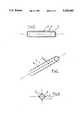
- FIG. 1is a perspective view of the tubular endoprosthesis according to the invention.
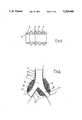
- FIG. 2is a lengthwise cross-section of the tubular endoprosthesis shown in FIG. 1.
- FIG. 3is a transverse cross-section of the tubular endoprosthesis shown in FIG. 2.
- FIG. 4is an enlarged view, in detail, of a lengthwise cross-section of one of the ends of the endoprosthesis.
- FIG. 5is a front view of an embodiment of utilizing the endoprosthesis according to the invention, to permit tracheal bronchus clearance.
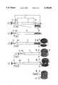
- FIG. 6is a view of the instruments permitting the placement of an endoprosthesis like the one illustrated in FIGS. 1-4.
- FIGS. 7-11show the operation of the placement instrument shown in FIG. 6 and the installation method for the tubular endoprosthesis according to the invention.
- FIG. 12is a front view of another embodiment of a tracheal bronchus endoprosthesis according to the invention.
- the tubular endoprosthesis according to the inventioncan, as a function of the shape of the anatomical conduit or channel inside which it is intended to be installed, affect a variety of shapes.
- Particular embodimentshave a simple rectilinear or essentially rectilinear shape (for example, when it is a tracheal endoprosthesis or bronchus endoprosthesis) as shown in FIG. 1, or a curved shape.
- Another embodimenthas a more complex shape with a principle tube extending into two divergent tubular branches (when it is a trachea bronchus endoprosthesis) as shown in FIG. 5.
- this endoprosthesiscan have any shape and any diameter adapted to the shape and the diameter of the conduits, channels or vessels inside which it is to be placed.
- the endoprosthesiscan be made in any supple, semi-rigid, or rigid material, and may be reinforced by an internal reinforcement capable of being well-tolerated by the organism.
- Preferred embodimentscan be advantageously made in a material with an elastic deformation capacity which in a particularly preferred embodiments is an elastomer silicon.
- the endoprosthesishas a tubular body 1 with an external surface 2, which is intended to come into contact with the internal wall of an anatomical conduit.
- External surface 2is provided with numerous protuberances or asperities 3, which may be distributed evenly over the entire external surface 2 or positions thereof.
- protuberances or asperities 3can have very different shapes, without edges that could injure the anatomical walls with which they are supposed to come into contact.
- the proterberances or asperities 3consist of nipples with rounded tops, arranged in lines oriented according to the rulings of the endoprosthesis; these lines of nipples can be angularly spaced, as shown particularly in FIG. 1.
- These nipples 3are radially-oriented in relation to the tubular body 1, and they are spaced from each other in the lengthwise direction as well as the peripheral direction. They can be advantageously distributed alternately on the lateral surface of the tubular body 1.
- the nipplescan have a circular or any other shaped section.
- these nipples or nibs 3are ineffaceable, that is, they are sufficiently rigid so that they don't compress, bend, or retract under the conditions of use.
- At least one, and preferably both ends, of the endoprosthesisare provided with an internal sloping edge 4 (FIG. 4), so that the ends consist of thin, tapered lips. This feature provides that when the endoprosthesis is in place, it forms no retention asperity favoring the formation of diverse accumulations as a function of the nature of the conduits, channels or vessels, at the entry or exit of the prosthesis.
- the alternative embodiment of the prosthesis illustrated in FIG. 5differs from the preceding only by its slightly more complex shape adapted to the conformation of the conduits in which it is to be installed.
- the prosthesisincludes a principal tubular body 1' extended by two divergent tubular branches 1"; the external surfaces 2', 2" of the main body and of the branches are provided with nipples 3, as previously described.
- Such a prosthesisis intended to be placed at the branching point of an anatomical conduit.
- such a prosthesisis intended to constitute a tracheobronchus endoprosthesis, allowing the conduit to remain open despite an obstruction S affecting both the internal part of the trachea T and the initial portion of the two bronchi B to be by-passed.
- FIG. 12shows another embodiment of a prosthesis according to the invention such as a tracheobronchus endoprosthesis, also intended to be placed at the branching point of an anatomical conduit, such as in the case of an obstruction S to be by-passed affecting only the base of the major conduit (trachea T, for example) and only one of the branches (one of the bronchi B', for example).
- the prosthesishas a curved shape and includes a major part 10 extended by a second part of smaller diameter 10'.
- the opening 9is intended to be placed at the entry of a second healthy branch of an anatomical conduit (the other bronchus B", for example), in order to permit a passage between the principal conduit T and a healthy branch B".
- the lateral opening 9can also allow and favor the installation of a second independent tubular branch similar to the secondary part 10', in order to create an endoprosthesis like the one shown in FIG. 5.
- FIG. 6We have shown in FIG. 6 an installation or introduction instrument for endoprosthesis consisting of a rectilinear or essentially rectilinear tube such as those which are intended to be installed in the trachea or in the weak, hardened or tumor-compressed bronchi, in order to serve as their support or to permit them to be cleared.
- This instrumentincludes a classic bronchoscope 6 on the elongated cylindrical body or guidance rod 6a, on which is mounted, with a sliding ability in relation to said rod, a tubular pusher 7 whose length L' is less than the length L of the guidance rod 6a.
- the difference in length between the rod 6a of the bronchoscope and the pusher 7corresponds at least to the length L" of the endoprosthesis 8 intended to be introduced and positioned with the help of the instrument; this difference in length (L--L') being, however, preferably greater than the length L' of the endoprosthesis.
- FIGS. 7-11show the installation procedure of a simple endoprosthesis 8 in an anatomical conduit B (for example, trachea or bronchus) obstructed by a compressive tumor S.
- anatomical conduit Bfor example, trachea or bronchus
- the endoprosthesis 8is first placed around the end of the rod 6a of the bronchoscope 6, in front of the pusher 7 (FIG. 7), the tapered end of the rod emerging at the front of the endoprosthesis, in order to facilitate its progress in the anatomical conduit.
- the rod furnished with endoprosthesis 8is then introduced and driven into the anatomical conduit B (FIG. 8) until said endoprosthesis reaches the desired position (FIG. 9), that is, the place where the hardening or compressive tumor is located.
- the rod 6a of the bronchoscopeis then withdrawn while maintaining the pusher 7 in place, which prevents any backwards movement of the endoprosthesis during this withdrawal (FIG. 10).
- the pusheris withdrawn, the endoprosthesis then being installed and solidly fixed in its lodging because of the nipples provided on its external surface, on which the surrounding anatomical wall exerts pressure preventing any shift or movement of the endoprosthesis.
Landscapes
- Health & Medical Sciences (AREA)
- Life Sciences & Earth Sciences (AREA)
- Animal Behavior & Ethology (AREA)
- Surgery (AREA)
- Veterinary Medicine (AREA)
- Public Health (AREA)
- Oral & Maxillofacial Surgery (AREA)
- Engineering & Computer Science (AREA)
- Biomedical Technology (AREA)
- Heart & Thoracic Surgery (AREA)
- General Health & Medical Sciences (AREA)
- Transplantation (AREA)
- Vascular Medicine (AREA)
- Cardiology (AREA)
- Pulmonology (AREA)
- Nuclear Medicine, Radiotherapy & Molecular Imaging (AREA)
- Pathology (AREA)
- Gastroenterology & Hepatology (AREA)
- Medical Informatics (AREA)
- Molecular Biology (AREA)
- Prostheses (AREA)
- Media Introduction/Drainage Providing Device (AREA)
Abstract
Description
1. Field of the Invention
The present invention concerns a tubular endoprosthesis for anatomical conduits or channels. Specifically, particular nonlimiting embodiments of this endoprosthesis are intended to permit the clearance of hardened conduits such as the trachea or bronchus, or to serve as a support for such anatomical conduits when they prove to be weak. Also described is an instrument to put this endoprosthesis in place.
2. Description of Background and Relevant Information
A hollow tube is disclosed in French Patent Document No. 1,130,165 for the treatment of hardening of the esophagus. The device constitutes a flexible tube with a ribbed external surface intended to be installed in a tumoral contraction to permit the passage of food.
This hollow tube has the drawback of not offering any guarantee that it will stay in place, because it can easily turn on itself, which can provoke irritation. Such irritation generates rejection spasms leading to axial shift of the tube, along with the serious consequences to which this shift can lead.
One of the objects of the present invention is to effectively remedy this serious insufficiency of known endoprostheses.
According to the invention, this objective is obtained by means of an endoprosthesis with a tubular body whose external surface is provided with numerous protuberances or asperities, preferably distributed over the entire surface, or a portion thereof. These protuberances consists of nipples with rounded tops, which are spaced from each other in the longitudinal and peripheral directions on the tubular body, and are preferably radially-oriented.
Another advantage of the endoprosthesis according to the invention is that it can be put easily in place and installs itself in a natural, extremely resistant fashion. In its implantation position, the prosthesis cannot, in effect, turn or slide axially when it is installed in the stenosis. In addition, this prosthesis may be made of a plastic material, such as an elastomer silicone, which is well tolerated by the organism whether healthy or ill, in whom it does not produce rejection spasms or trauma.
In another embodiment of the tubular endoprosthesis according to the invention, the nipples are arranged in lines with spaces in between them and are oriented along the rulings of the tubular body of the endoprosthesis.
The nipples can also be alternatingly distributed on the external surface of the tubular body.
In another embodiment of the tubular endoprosthesis according to the invention, at least one of its ends has an internal slanted wall. Optionally, both or all of its ends may have an internal slanted wall.
The goals, characteristics, and advantages above, and others, will be more apparent from the following description and the attached Figures.
FIG. 1 is a perspective view of the tubular endoprosthesis according to the invention.
FIG. 2 is a lengthwise cross-section of the tubular endoprosthesis shown in FIG. 1.
FIG. 3 is a transverse cross-section of the tubular endoprosthesis shown in FIG. 2.
FIG. 4 is an enlarged view, in detail, of a lengthwise cross-section of one of the ends of the endoprosthesis.
FIG. 5 is a front view of an embodiment of utilizing the endoprosthesis according to the invention, to permit tracheal bronchus clearance.
FIG. 6 is a view of the instruments permitting the placement of an endoprosthesis like the one illustrated in FIGS. 1-4.
FIGS. 7-11 show the operation of the placement instrument shown in FIG. 6 and the installation method for the tubular endoprosthesis according to the invention.
FIG. 12 is a front view of another embodiment of a tracheal bronchus endoprosthesis according to the invention.
We refer to the following embodiments to describe the non-limiting construction of this endoprosthesis, as well as the use of instruments permitting its installation.
The tubular endoprosthesis according to the invention can, as a function of the shape of the anatomical conduit or channel inside which it is intended to be installed, affect a variety of shapes. Particular embodiments have a simple rectilinear or essentially rectilinear shape (for example, when it is a tracheal endoprosthesis or bronchus endoprosthesis) as shown in FIG. 1, or a curved shape. Another embodiment has a more complex shape with a principle tube extending into two divergent tubular branches (when it is a trachea bronchus endoprosthesis) as shown in FIG. 5. More precisely, this endoprosthesis can have any shape and any diameter adapted to the shape and the diameter of the conduits, channels or vessels inside which it is to be placed. The endoprosthesis can be made in any supple, semi-rigid, or rigid material, and may be reinforced by an internal reinforcement capable of being well-tolerated by the organism. Preferred embodiments can be advantageously made in a material with an elastic deformation capacity which in a particularly preferred embodiments is an elastomer silicon.
According to one embodiment of the invention, the endoprosthesis has atubular body 1 with anexternal surface 2, which is intended to come into contact with the internal wall of an anatomical conduit.External surface 2 is provided with numerous protuberances orasperities 3, which may be distributed evenly over the entireexternal surface 2 or positions thereof.
These protuberances orasperities 3 can have very different shapes, without edges that could injure the anatomical walls with which they are supposed to come into contact. In a preferred embodiment the proterberances orasperities 3 consist of nipples with rounded tops, arranged in lines oriented according to the rulings of the endoprosthesis; these lines of nipples can be angularly spaced, as shown particularly in FIG. 1. Thesenipples 3 are radially-oriented in relation to thetubular body 1, and they are spaced from each other in the lengthwise direction as well as the peripheral direction. They can be advantageously distributed alternately on the lateral surface of thetubular body 1. The nipples can have a circular or any other shaped section. Also, these nipples ornibs 3 are ineffaceable, that is, they are sufficiently rigid so that they don't compress, bend, or retract under the conditions of use.
At least one, and preferably both ends, of the endoprosthesis are provided with an internal sloping edge 4 (FIG. 4), so that the ends consist of thin, tapered lips. This feature provides that when the endoprosthesis is in place, it forms no retention asperity favoring the formation of diverse accumulations as a function of the nature of the conduits, channels or vessels, at the entry or exit of the prosthesis.
The alternative embodiment of the prosthesis illustrated in FIG. 5 differs from the preceding only by its slightly more complex shape adapted to the conformation of the conduits in which it is to be installed. According to this variation of construction, the prosthesis includes a principal tubular body 1' extended by two divergenttubular branches 1"; theexternal surfaces 2', 2" of the main body and of the branches are provided withnipples 3, as previously described. Such a prosthesis is intended to be placed at the branching point of an anatomical conduit. According to a very interesting application, such a prosthesis is intended to constitute a tracheobronchus endoprosthesis, allowing the conduit to remain open despite an obstruction S affecting both the internal part of the trachea T and the initial portion of the two bronchi B to be by-passed.
FIG. 12 shows another embodiment of a prosthesis according to the invention such as a tracheobronchus endoprosthesis, also intended to be placed at the branching point of an anatomical conduit, such as in the case of an obstruction S to be by-passed affecting only the base of the major conduit (trachea T, for example) and only one of the branches (one of the bronchi B', for example). In this case, the prosthesis has a curved shape and includes amajor part 10 extended by a second part of smaller diameter 10'. In addition, it has an opening 9 laterally placed at the juncture point of themajor part 10 and secondary part 10', the opening 9 is intended to be placed at the entry of a second healthy branch of an anatomical conduit (the other bronchus B", for example), in order to permit a passage between the principal conduit T and a healthy branch B".
The lateral opening 9 can also allow and favor the installation of a second independent tubular branch similar to the secondary part 10', in order to create an endoprosthesis like the one shown in FIG. 5.
We have shown in FIG. 6 an installation or introduction instrument for endoprosthesis consisting of a rectilinear or essentially rectilinear tube such as those which are intended to be installed in the trachea or in the weak, hardened or tumor-compressed bronchi, in order to serve as their support or to permit them to be cleared.
This instrument includes aclassic bronchoscope 6 on the elongated cylindrical body orguidance rod 6a, on which is mounted, with a sliding ability in relation to said rod, atubular pusher 7 whose length L' is less than the length L of theguidance rod 6a. The difference in length between therod 6a of the bronchoscope and thepusher 7 corresponds at least to the length L" of theendoprosthesis 8 intended to be introduced and positioned with the help of the instrument; this difference in length (L--L') being, however, preferably greater than the length L' of the endoprosthesis.
FIGS. 7-11 show the installation procedure of asimple endoprosthesis 8 in an anatomical conduit B (for example, trachea or bronchus) obstructed by a compressive tumor S.
Theendoprosthesis 8 is first placed around the end of therod 6a of thebronchoscope 6, in front of the pusher 7 (FIG. 7), the tapered end of the rod emerging at the front of the endoprosthesis, in order to facilitate its progress in the anatomical conduit.
The rod furnished withendoprosthesis 8 is then introduced and driven into the anatomical conduit B (FIG. 8) until said endoprosthesis reaches the desired position (FIG. 9), that is, the place where the hardening or compressive tumor is located.
Therod 6a of the bronchoscope is then withdrawn while maintaining thepusher 7 in place, which prevents any backwards movement of the endoprosthesis during this withdrawal (FIG. 10). Finally, the pusher is withdrawn, the endoprosthesis then being installed and solidly fixed in its lodging because of the nipples provided on its external surface, on which the surrounding anatomical wall exerts pressure preventing any shift or movement of the endoprosthesis.
Claims (11)
1. Tubular endoprosthesis for anatomical conduits, comprising:
a biocompatible tubular body composed of a semi-rigid or rigid material having an external surface and two open ends forming a passage therethrough, said body adapted to contact an internal wall of the anatomical conduit; and
means forming a plurality of discrete protuberances distributed on said external surface for maintaining said tubular body within said anatomical conduit against return or axial displacement without injuring the internal wall of the anatomical conduit; and
said means forming a plurality of protuberances comprising ineffaceable nipples having rounded tops, with said nipples being spaced along the length and periphery of said external surface of said tubular body.
2. The tubular endoprosthesis according to claim 1, wherein said nipples are radially oriented with respect to said tubular body.
3. The tubular endoprosthesis according to claim 1, wherein said nipples having rounded tops are distributed over substantially the entire external surface of said tubular body.
4. The tubular endoprosthesis according to claim 1, wherein said nipples are arranged in lines which are spaced from each other along said length of the external surface.
5. The tubular endoprosthesis according to claim 4, wherein said lines are positioned along rulings of said tubular body.
6. The tubular endoprosthesis according to claim 5, wherein said nipples are alternately distributed along said tubular body.
7. The tubular endoprosthesis according to claim 1, wherein said semi-rigid or rigid material comprises a material having elastic deformation ability.
8. The tubular endoprosthesis according to claim 7, wherein said material is an elastomeric silicone.
9. The tubular endoprosthesis according to claim 1, wherein said tubular body includes a lateral opening adapted to maintain a passage between an anatomical conduit in which the tubular endoprosthesis is positioned and a branch thereof.
10. Tubular endoprosthesis for anatomical conduits, comprising:
a biocompatible tubular body having an external surface, wherein said tubular body includes two open ends, and at least one of said two ends has an internal slanted wall; and
means forming a plurality of protuberances distributed on said external surface for maintaining said tubular body in an anatomical conduit without injuring anatomical walls of the anatomical conduit; and
said means forming a plurality of protuberances comprising nipples having rounded tops, with said nipples being spaced along the length and periphery of said external surface of said tubular body.
11. The tubular endoprosthesis according to claim 10, wherein each of said two ends has an internal slanted wall.
Applications Claiming Priority (2)
| Application Number | Priority Date | Filing Date | Title |
|---|---|---|---|
| FR8802835AFR2627982B1 (en) | 1988-03-02 | 1988-03-02 | TUBULAR ENDOPROSTHESIS FOR ANATOMICAL CONDUITS, AND INSTRUMENT AND METHOD FOR ITS PLACEMENT |
| FR8802835 | 1988-03-02 |
Publications (1)
| Publication Number | Publication Date |
|---|---|
| US5236446Atrue US5236446A (en) | 1993-08-17 |
Family
ID=9363950
Family Applications (1)
| Application Number | Title | Priority Date | Filing Date |
|---|---|---|---|
| US07/566,350Expired - LifetimeUS5236446A (en) | 1988-03-02 | 1989-03-02 | Tubular endoprosthesis for anatomical conduits |
Country Status (8)
| Country | Link |
|---|---|
| US (1) | US5236446A (en) |
| EP (1) | EP0440618B1 (en) |
| JP (1) | JP2740030B2 (en) |
| AU (1) | AU3215389A (en) |
| CA (1) | CA1298438C (en) |
| ES (1) | ES2010469A6 (en) |
| FR (1) | FR2627982B1 (en) |
| WO (1) | WO1989007916A1 (en) |
Cited By (54)
| Publication number | Priority date | Publication date | Assignee | Title |
|---|---|---|---|---|
| US5569295A (en) | 1993-12-28 | 1996-10-29 | Advanced Cardiovascular Systems, Inc. | Expandable stents and method for making same |
| US5591197A (en)* | 1995-03-14 | 1997-01-07 | Advanced Cardiovascular Systems, Inc. | Expandable stent forming projecting barbs and method for deploying |
| US5609627A (en)* | 1994-02-09 | 1997-03-11 | Boston Scientific Technology, Inc. | Method for delivering a bifurcated endoluminal prosthesis |
| US5676696A (en)* | 1995-02-24 | 1997-10-14 | Intervascular, Inc. | Modular bifurcated intraluminal grafts and methods for delivering and assembling same |
| US6039754A (en)* | 1993-10-01 | 2000-03-21 | Imperial College Of Science Technology & Medicine | Vascular prostheses |
| US6051020A (en)* | 1994-02-09 | 2000-04-18 | Boston Scientific Technology, Inc. | Bifurcated endoluminal prosthesis |
| US6053943A (en)* | 1995-12-08 | 2000-04-25 | Impra, Inc. | Endoluminal graft with integral structural support and method for making same |
| US6099558A (en)* | 1995-10-10 | 2000-08-08 | Edwards Lifesciences Corp. | Intraluminal grafting of a bifuricated artery |
| US6110191A (en)* | 1996-09-12 | 2000-08-29 | Edwards Lifesciences, Llc | Endovascular delivery system |
| US6165213A (en)* | 1994-02-09 | 2000-12-26 | Boston Scientific Technology, Inc. | System and method for assembling an endoluminal prosthesis |
| US6287330B1 (en) | 1996-09-03 | 2001-09-11 | Endovascular Technologies, Inc. | Aortoiliac grafting system and method |
| US6309411B1 (en)* | 1994-10-19 | 2001-10-30 | Medtronic Ave, Inc. | Method and apparatus to prevent stent migration |
| US6344056B1 (en) | 1999-12-29 | 2002-02-05 | Edwards Lifesciences Corp. | Vascular grafts for bridging a vessel side branch |
| US6454794B1 (en)* | 1996-08-13 | 2002-09-24 | Heartstent Corporation | Coronary bypass implant |
| US6565596B1 (en) | 1993-09-30 | 2003-05-20 | Endogad Research Pty Limited | Intraluminal graft |
| EP0740537B1 (en)* | 1993-12-23 | 2003-07-02 | H.K. Medical Technologies Incorporated | Nonsurgical intraurethral bladder control device |
| US6607539B1 (en) | 2001-05-18 | 2003-08-19 | Endovascular Technologies, Inc. | Electric endovascular implant depolyment system |
| US6635082B1 (en) | 2000-12-29 | 2003-10-21 | Advanced Cardiovascular Systems Inc. | Radiopaque stent |
| US6641607B1 (en) | 2000-12-29 | 2003-11-04 | Advanced Cardiovascular Systems, Inc. | Double tube stent |
| US6652579B1 (en) | 2000-06-22 | 2003-11-25 | Advanced Cardiovascular Systems, Inc. | Radiopaque stent |
| US6663667B2 (en) | 1999-12-29 | 2003-12-16 | Edwards Lifesciences Corporation | Towel graft means for enhancing tissue ingrowth in vascular grafts |
| US6685736B1 (en) | 1993-09-30 | 2004-02-03 | Endogad Research Pty Limited | Intraluminal graft |
| US20040148032A1 (en)* | 2003-01-29 | 2004-07-29 | Rutter Michael John | Airway stent |
| US20040153136A1 (en)* | 2001-05-18 | 2004-08-05 | Vardi Gil M. | Dual guidewire exchange catheter system |
| US6773455B2 (en) | 1997-06-24 | 2004-08-10 | Advanced Cardiovascular Systems, Inc. | Stent with reinforced struts and bimodal deployment |
| US20050015108A1 (en)* | 2003-07-18 | 2005-01-20 | Advanced Stent Technologies, Inc. | Catheter balloon systems and methods |
| US6884258B2 (en) | 1999-06-04 | 2005-04-26 | Advanced Stent Technologies, Inc. | Bifurcation lesion stent delivery using multiple guidewires |
| US6962602B2 (en) | 1996-11-04 | 2005-11-08 | Advanced Stent Tech Llc | Method for employing an extendible stent apparatus |
| US20060161264A1 (en)* | 2005-01-18 | 2006-07-20 | Novatech Sa | Endoprosthesis for anatomical canal |
| US7341598B2 (en) | 1999-01-13 | 2008-03-11 | Boston Scientific Scimed, Inc. | Stent with protruding branch portion for bifurcated vessels |
| US7344557B2 (en) | 2003-11-12 | 2008-03-18 | Advanced Stent Technologies, Inc. | Catheter balloon systems and methods |
| US7591846B2 (en) | 1996-11-04 | 2009-09-22 | Boston Scientific Scimed, Inc. | Methods for deploying stents in bifurcations |
| US20090311132A1 (en)* | 1995-03-10 | 2009-12-17 | C.R. Bard, Inc. | Methods for making a supported graft |
| US7678142B2 (en) | 1996-11-04 | 2010-03-16 | Boston Scientific Scimed, Inc. | Extendible stent apparatus |
| USD616086S1 (en)* | 2009-09-28 | 2010-05-18 | Joseph Barbagiovanni | Condom |
| US7771462B1 (en) | 1999-06-04 | 2010-08-10 | Boston Scientific Scimed, Inc. | Catheter with side sheath and methods |
| USRE42380E1 (en) | 1993-06-25 | 2011-05-17 | Bypass Devices LLC | Surgical bypass method |
| US20110126966A1 (en)* | 1999-02-02 | 2011-06-02 | C.R. Bard, Inc. | Partial encapsulation of stents |
| US20120035715A1 (en)* | 2010-08-09 | 2012-02-09 | Boston Scientific Scimed, Inc. | Tracheal Stent With Longitudinal Ribs to Minimize Stent Movement, Coughing and Halitosis |
| US8196279B2 (en) | 2008-02-27 | 2012-06-12 | C. R. Bard, Inc. | Stent-graft covering process |
| US8206427B1 (en) | 1994-06-08 | 2012-06-26 | Medtonic Vascular, Inc. | Apparatus and methods for endoluminal graft placement |
| US8298280B2 (en) | 2003-08-21 | 2012-10-30 | Boston Scientific Scimed, Inc. | Stent with protruding branch portion for bifurcated vessels |
| US8377108B2 (en) | 2008-06-02 | 2013-02-19 | Boston Scientific Scimed, Inc. | Staggered two balloon bifurcation catheter assembly and methods |
| US8486134B2 (en) | 2007-08-01 | 2013-07-16 | Boston Scientific Scimed, Inc. | Bifurcation treatment system and methods |
| US8617441B2 (en) | 1995-03-10 | 2013-12-31 | Bard Peripheral Vascular, Inc. | Methods for making an encapsulated stent |
| US8747456B2 (en) | 2007-12-31 | 2014-06-10 | Boston Scientific Scimed, Inc. | Bifurcation stent delivery system and methods |
| US8821561B2 (en) | 2006-02-22 | 2014-09-02 | Boston Scientific Scimed, Inc. | Marker arrangement for bifurcation catheter |
| US8827954B2 (en) | 2008-06-05 | 2014-09-09 | Boston Scientific Scimed, Inc. | Deflatable bifurcated device |
| US8936567B2 (en) | 2007-11-14 | 2015-01-20 | Boston Scientific Scimed, Inc. | Balloon bifurcated lumen treatment |
| US20160232804A1 (en)* | 2015-02-05 | 2016-08-11 | William James Nichols | Fidget Sleeve |
| US9561126B2 (en) | 1996-11-04 | 2017-02-07 | Boston Scientific Scimed, Inc. | Catheter with attached flexible side sheath |
| CN107174384A (en)* | 2017-06-30 | 2017-09-19 | 芜湖启泽信息技术有限公司 | A kind of 3D printing trachea bracket |
| USD865059S1 (en)* | 2018-06-14 | 2019-10-29 | Lisa D. Lahey | Page turning device |
| US10470871B2 (en) | 2001-12-20 | 2019-11-12 | Trivascular, Inc. | Advanced endovascular graft |
Families Citing this family (11)
| Publication number | Priority date | Publication date | Assignee | Title |
|---|---|---|---|---|
| DE4122923C1 (en)* | 1991-07-11 | 1993-01-28 | Willy Ruesch Ag, 7053 Kernen, De | |
| AU713514B2 (en)* | 1994-10-19 | 1999-12-02 | Arterial Vascular Engineering, Inc | Stent surface anchor |
| US5669930A (en)* | 1994-12-08 | 1997-09-23 | Fuji Systems Corporation | Stent for intracorporeal retention |
| FR2750315B1 (en)* | 1996-06-26 | 1998-12-18 | Novatech Inc | INTRALARYNGEAL PROSTHESIS |
| NL1004042C2 (en)* | 1996-09-16 | 1998-03-17 | Paul Ferdinand Schouwenburg | Voice prosthesis with improved sealing. |
| FR2768920B1 (en)* | 1997-10-01 | 2000-01-21 | Bernard Dumas | POLYURETHANE TRACHEOBRONCHIC PROSTHESES |
| RU2153863C2 (en)* | 1998-06-01 | 2000-08-10 | Московский государственный институт стали и сплавов (технологический университет) | Prosthesis for endoprosthetics of vessels and hollow organs and device for its implantation (versions) |
| FR2789889B1 (en)* | 1999-02-18 | 2001-04-27 | Tokendo Sarl | SYSTEM FOR LAYING SEMI-RIGID TUBULAR ENDOPROSTHESES |
| UA82705C2 (en)* | 2006-02-20 | 2008-05-12 | Vasylenko Viktor Volodymyrovyc | Blood vessel prosthesis |
| FR2941862B1 (en)* | 2009-02-12 | 2011-04-01 | Tokendo | TRACHEAL OR TRACHEOBRONCHIC ENDOPROTHESIS |
| FR3048874B1 (en) | 2016-03-16 | 2018-04-27 | Anatomikmodeling | METHOD FOR MANUFACTURING TUBULAR STENT FOR IMPLANTATION IN ANATOMIC CONDUIT |
Citations (18)
| Publication number | Priority date | Publication date | Assignee | Title |
|---|---|---|---|---|
| US2701559A (en)* | 1951-08-02 | 1955-02-08 | William A Cooper | Apparatus for exfoliating and collecting diagnostic material from inner walls of hollow viscera |
| FR1103165A (en)* | 1954-06-25 | 1955-10-31 | Device for the treatment of stenosis of the esophagus | |
| FR2122032A5 (en)* | 1971-01-15 | 1972-08-25 | Rhone Poulenc Sa | |
| US3818515A (en)* | 1972-11-13 | 1974-06-25 | W Neville | Bifurcated tracheo-bronchial prostheses |
| US3818511A (en)* | 1972-11-17 | 1974-06-25 | Medical Prod Corp | Medical prosthesis for ducts or conduits |
| FR2248015A1 (en)* | 1973-10-17 | 1975-05-16 | Rhone Poulenc Ind | Artificial ureter or urethra - watertight flexible tube has helical rib in outside wall to prevent creasing |
| FR2391709A2 (en)* | 1975-12-02 | 1978-12-22 | Rhone Poulenc Ind | Implantable surgical tubing with sewable ends - has radially elastic wall including a fleece layer and reinforcement |
| US4164045A (en)* | 1977-08-03 | 1979-08-14 | Carbomedics, Inc. | Artificial vascular and patch grafts |
| GB1565828A (en)* | 1975-12-02 | 1980-04-23 | Plastiques Ind Soc | Implantable surgical pipeline |
| US4224933A (en)* | 1978-10-10 | 1980-09-30 | Joseph William Reiling | Sexual stabilizer and stimulator |
| EP0146794A2 (en)* | 1983-12-16 | 1985-07-03 | B. Braun-SSC AG | Method for the production of a artery prosthesis |
| US4592341A (en)* | 1984-05-23 | 1986-06-03 | Olympus Optical Co., Ltd. | Method and apparatus for guiding prosthesis |
| US4699611A (en)* | 1985-04-19 | 1987-10-13 | C. R. Bard, Inc. | Biliary stent introducer |
| US4728328A (en)* | 1984-10-19 | 1988-03-01 | Research Corporation | Cuffed tubular organic prostheses |
| US4732152A (en)* | 1984-12-05 | 1988-03-22 | Medinvent S.A. | Device for implantation and a method of implantation in a vessel using such device |
| US4852586A (en)* | 1988-02-26 | 1989-08-01 | Haines Bernard M | Sensory transmitting membrane device |
| US4863477A (en)* | 1987-05-12 | 1989-09-05 | Monson Gary L | Synthetic intervertebral disc prosthesis |
| US4955909A (en)* | 1989-01-31 | 1990-09-11 | Bioplasty, Inc. | Textured silicone implant prosthesis |
- 1988
- 1988-03-02FRFR8802835Apatent/FR2627982B1/ennot_activeExpired - Lifetime
- 1989
- 1989-03-02WOPCT/FR1989/000083patent/WO1989007916A1/enactiveIP Right Grant
- 1989-03-02CACA000592640Apatent/CA1298438C/ennot_activeExpired - Lifetime
- 1989-03-02USUS07/566,350patent/US5236446A/ennot_activeExpired - Lifetime
- 1989-03-02ESES8901086Apatent/ES2010469A6/ennot_activeExpired
- 1989-03-02JPJP1502977Apatent/JP2740030B2/ennot_activeExpired - Lifetime
- 1989-03-02AUAU32153/89Apatent/AU3215389A/ennot_activeAbandoned
- 1989-03-02EPEP89903184Apatent/EP0440618B1/ennot_activeExpired - Lifetime
Patent Citations (19)
| Publication number | Priority date | Publication date | Assignee | Title |
|---|---|---|---|---|
| US2701559A (en)* | 1951-08-02 | 1955-02-08 | William A Cooper | Apparatus for exfoliating and collecting diagnostic material from inner walls of hollow viscera |
| FR1103165A (en)* | 1954-06-25 | 1955-10-31 | Device for the treatment of stenosis of the esophagus | |
| FR2122032A5 (en)* | 1971-01-15 | 1972-08-25 | Rhone Poulenc Sa | |
| US3818515A (en)* | 1972-11-13 | 1974-06-25 | W Neville | Bifurcated tracheo-bronchial prostheses |
| US3818511A (en)* | 1972-11-17 | 1974-06-25 | Medical Prod Corp | Medical prosthesis for ducts or conduits |
| FR2248015A1 (en)* | 1973-10-17 | 1975-05-16 | Rhone Poulenc Ind | Artificial ureter or urethra - watertight flexible tube has helical rib in outside wall to prevent creasing |
| GB1565828A (en)* | 1975-12-02 | 1980-04-23 | Plastiques Ind Soc | Implantable surgical pipeline |
| FR2391709A2 (en)* | 1975-12-02 | 1978-12-22 | Rhone Poulenc Ind | Implantable surgical tubing with sewable ends - has radially elastic wall including a fleece layer and reinforcement |
| US4164045A (en)* | 1977-08-03 | 1979-08-14 | Carbomedics, Inc. | Artificial vascular and patch grafts |
| US4224933A (en)* | 1978-10-10 | 1980-09-30 | Joseph William Reiling | Sexual stabilizer and stimulator |
| EP0146794A2 (en)* | 1983-12-16 | 1985-07-03 | B. Braun-SSC AG | Method for the production of a artery prosthesis |
| US4588461A (en)* | 1983-12-16 | 1986-05-13 | Intermedient Gmbh | Process for producing a vessel prosthesis |
| US4592341A (en)* | 1984-05-23 | 1986-06-03 | Olympus Optical Co., Ltd. | Method and apparatus for guiding prosthesis |
| US4728328A (en)* | 1984-10-19 | 1988-03-01 | Research Corporation | Cuffed tubular organic prostheses |
| US4732152A (en)* | 1984-12-05 | 1988-03-22 | Medinvent S.A. | Device for implantation and a method of implantation in a vessel using such device |
| US4699611A (en)* | 1985-04-19 | 1987-10-13 | C. R. Bard, Inc. | Biliary stent introducer |
| US4863477A (en)* | 1987-05-12 | 1989-09-05 | Monson Gary L | Synthetic intervertebral disc prosthesis |
| US4852586A (en)* | 1988-02-26 | 1989-08-01 | Haines Bernard M | Sensory transmitting membrane device |
| US4955909A (en)* | 1989-01-31 | 1990-09-11 | Bioplasty, Inc. | Textured silicone implant prosthesis |
Non-Patent Citations (2)
| Title |
|---|
| Copy of International Preliminary Examination.* |
| Copy of International Search Report with annex.* |
Cited By (99)
| Publication number | Priority date | Publication date | Assignee | Title |
|---|---|---|---|---|
| USRE42380E1 (en) | 1993-06-25 | 2011-05-17 | Bypass Devices LLC | Surgical bypass method |
| US6685736B1 (en) | 1993-09-30 | 2004-02-03 | Endogad Research Pty Limited | Intraluminal graft |
| US6582458B1 (en) | 1993-09-30 | 2003-06-24 | Geoffrey H. White | Intraluminal graft |
| US6565596B1 (en) | 1993-09-30 | 2003-05-20 | Endogad Research Pty Limited | Intraluminal graft |
| US6689158B1 (en) | 1993-09-30 | 2004-02-10 | Endogad Research Pty Limited | Intraluminal graft |
| US8052742B2 (en) | 1993-09-30 | 2011-11-08 | Gore Enterprise Holding, Inc. | Intraluminal graft |
| US6613073B1 (en) | 1993-09-30 | 2003-09-02 | Endogad Research Pty Limited | Intraluminal graft |
| US6039754A (en)* | 1993-10-01 | 2000-03-21 | Imperial College Of Science Technology & Medicine | Vascular prostheses |
| EP0740537B1 (en)* | 1993-12-23 | 2003-07-02 | H.K. Medical Technologies Incorporated | Nonsurgical intraurethral bladder control device |
| US5916234A (en) | 1993-12-28 | 1999-06-29 | Advanced Cardiovascular Systems, Inc. | Expandable stents and method for making same |
| US5649952A (en) | 1993-12-28 | 1997-07-22 | Advanced Cardiovascular Systems, Inc. | Expandable stents and method for making same |
| US5569295A (en) | 1993-12-28 | 1996-10-29 | Advanced Cardiovascular Systems, Inc. | Expandable stents and method for making same |
| US5693086A (en)* | 1994-02-09 | 1997-12-02 | Boston Scientific Technology, Inc. | Apparatus for delivering an endoluminal stent or prosthesis |
| US6117167A (en)* | 1994-02-09 | 2000-09-12 | Boston Scientific Technology, Inc. | Endoluminal prosthesis and system for joining |
| US5800508A (en)* | 1994-02-09 | 1998-09-01 | Boston Scientific Technology, Inc. | Bifurcated endoluminal prosthesis |
| US5938696A (en)* | 1994-02-09 | 1999-08-17 | Boston Scientific Technology, Inc. | Bifurcated endoluminal prosthesis |
| US5776180A (en)* | 1994-02-09 | 1998-07-07 | Boston Scientific Technology | Bifurcated endoluminal prosthesis |
| US6051020A (en)* | 1994-02-09 | 2000-04-18 | Boston Scientific Technology, Inc. | Bifurcated endoluminal prosthesis |
| US5718724A (en)* | 1994-02-09 | 1998-02-17 | Boston Scientific Technology, Inc. | Bifurcated endoluminal prosthesis |
| US7942919B2 (en) | 1994-02-09 | 2011-05-17 | Scimed Life Systems, Inc. | Bifurcated endoluminal prosthesis |
| US7901449B2 (en) | 1994-02-09 | 2011-03-08 | Scimed Life Systems, Inc. | Bifurcated endoluminal prosthesis |
| US5916263A (en)* | 1994-02-09 | 1999-06-29 | Boston Scientific Technology, Inc. | Bifurcated endoluminal prosthesis |
| US6165213A (en)* | 1994-02-09 | 2000-12-26 | Boston Scientific Technology, Inc. | System and method for assembling an endoluminal prosthesis |
| US7780720B2 (en) | 1994-02-09 | 2010-08-24 | Scimed Life Systems, Inc. | Bifurcated endoluminal prosthesis |
| US6302906B1 (en) | 1994-02-09 | 2001-10-16 | Boston Scientific Technology, Inc. | System for delivering a prosthesis |
| US5716365A (en)* | 1994-02-09 | 1998-02-10 | Boston Scientific Technologies, Inc. | Bifurcated endoluminal prosthesis |
| US7510570B1 (en) | 1994-02-09 | 2009-03-31 | Boston Scientific Scimed, Inc. | Bifurcated endoluminal prosthesis |
| US5683450A (en)* | 1994-02-09 | 1997-11-04 | Boston Scientific Technology, Inc. | Bifurcated endoluminal prosthesis |
| US8192482B2 (en) | 1994-02-09 | 2012-06-05 | Scimed Life Systems, Inc. | Endoluminal stent |
| US5609627A (en)* | 1994-02-09 | 1997-03-11 | Boston Scientific Technology, Inc. | Method for delivering a bifurcated endoluminal prosthesis |
| US8206427B1 (en) | 1994-06-08 | 2012-06-26 | Medtonic Vascular, Inc. | Apparatus and methods for endoluminal graft placement |
| US8317854B1 (en) | 1994-06-08 | 2012-11-27 | Medtronic Vascular, Inc. | Apparatus and methods for endoluminal graft placement |
| US6309411B1 (en)* | 1994-10-19 | 2001-10-30 | Medtronic Ave, Inc. | Method and apparatus to prevent stent migration |
| US5676696A (en)* | 1995-02-24 | 1997-10-14 | Intervascular, Inc. | Modular bifurcated intraluminal grafts and methods for delivering and assembling same |
| US5683449A (en)* | 1995-02-24 | 1997-11-04 | Marcade; Jean Paul | Modular bifurcated intraluminal grafts and methods for delivering and assembling same |
| US20090311132A1 (en)* | 1995-03-10 | 2009-12-17 | C.R. Bard, Inc. | Methods for making a supported graft |
| US8647458B2 (en) | 1995-03-10 | 2014-02-11 | Bard Peripheral Vascular, Inc. | Methods for making a supported graft |
| US8617441B2 (en) | 1995-03-10 | 2013-12-31 | Bard Peripheral Vascular, Inc. | Methods for making an encapsulated stent |
| US8337650B2 (en) | 1995-03-10 | 2012-12-25 | Bard Peripheral Vascular, Inc. | Methods for making a supported graft |
| US8157940B2 (en) | 1995-03-10 | 2012-04-17 | Bard Peripheral Vascular, Inc. | Methods for making a supported graft |
| US5591197A (en)* | 1995-03-14 | 1997-01-07 | Advanced Cardiovascular Systems, Inc. | Expandable stent forming projecting barbs and method for deploying |
| US5681346A (en)* | 1995-03-14 | 1997-10-28 | Advanced Cardiovascular Systems, Inc. | Expandable stent forming projecting barbs and method for deploying |
| US6099558A (en)* | 1995-10-10 | 2000-08-08 | Edwards Lifesciences Corp. | Intraluminal grafting of a bifuricated artery |
| US6053943A (en)* | 1995-12-08 | 2000-04-25 | Impra, Inc. | Endoluminal graft with integral structural support and method for making same |
| US6454794B1 (en)* | 1996-08-13 | 2002-09-24 | Heartstent Corporation | Coronary bypass implant |
| US20040077990A1 (en)* | 1996-08-13 | 2004-04-22 | Heartstent Corporation | Method and apparatus for revascularizing a coronary vessel with an implant having a tapered myocardial leg |
| US6913021B2 (en) | 1996-08-13 | 2005-07-05 | Percardia, Inc. | Method for revascularizing a coronary vessel |
| US6929011B2 (en) | 1996-08-13 | 2005-08-16 | Percardia, Inc. | Method to deliver blood from a heart chamber to a vessel |
| US20040122347A1 (en)* | 1996-08-13 | 2004-06-24 | Percardia, Inc. | Method and apparatus for revascularizing a coronary vessel with an implant having a tapered myocardial leg |
| US6287330B1 (en) | 1996-09-03 | 2001-09-11 | Endovascular Technologies, Inc. | Aortoiliac grafting system and method |
| US6110191A (en)* | 1996-09-12 | 2000-08-29 | Edwards Lifesciences, Llc | Endovascular delivery system |
| US7591846B2 (en) | 1996-11-04 | 2009-09-22 | Boston Scientific Scimed, Inc. | Methods for deploying stents in bifurcations |
| US6962602B2 (en) | 1996-11-04 | 2005-11-08 | Advanced Stent Tech Llc | Method for employing an extendible stent apparatus |
| US8771342B2 (en) | 1996-11-04 | 2014-07-08 | Boston Scientific Scimed, Inc. | Methods for deploying stents in bifurcations |
| US9561126B2 (en) | 1996-11-04 | 2017-02-07 | Boston Scientific Scimed, Inc. | Catheter with attached flexible side sheath |
| US7678142B2 (en) | 1996-11-04 | 2010-03-16 | Boston Scientific Scimed, Inc. | Extendible stent apparatus |
| US20090132028A1 (en)* | 1996-11-04 | 2009-05-21 | Advanced Stent Technologies, Inc. | Extendible Stent Apparatus and Method for Deploying the Same |
| US6773455B2 (en) | 1997-06-24 | 2004-08-10 | Advanced Cardiovascular Systems, Inc. | Stent with reinforced struts and bimodal deployment |
| US7341598B2 (en) | 1999-01-13 | 2008-03-11 | Boston Scientific Scimed, Inc. | Stent with protruding branch portion for bifurcated vessels |
| US8617337B2 (en) | 1999-02-02 | 2013-12-31 | Bard Peripheral Vascular, Inc. | Partial encapsulation of stents |
| US20110126966A1 (en)* | 1999-02-02 | 2011-06-02 | C.R. Bard, Inc. | Partial encapsulation of stents |
| US10213328B2 (en) | 1999-02-02 | 2019-02-26 | Bard Peripheral Vascular, Inc. | Partial encapsulation of stents |
| US7771462B1 (en) | 1999-06-04 | 2010-08-10 | Boston Scientific Scimed, Inc. | Catheter with side sheath and methods |
| US6884258B2 (en) | 1999-06-04 | 2005-04-26 | Advanced Stent Technologies, Inc. | Bifurcation lesion stent delivery using multiple guidewires |
| US6344056B1 (en) | 1999-12-29 | 2002-02-05 | Edwards Lifesciences Corp. | Vascular grafts for bridging a vessel side branch |
| US6663667B2 (en) | 1999-12-29 | 2003-12-16 | Edwards Lifesciences Corporation | Towel graft means for enhancing tissue ingrowth in vascular grafts |
| US6652579B1 (en) | 2000-06-22 | 2003-11-25 | Advanced Cardiovascular Systems, Inc. | Radiopaque stent |
| US6635082B1 (en) | 2000-12-29 | 2003-10-21 | Advanced Cardiovascular Systems Inc. | Radiopaque stent |
| US6641607B1 (en) | 2000-12-29 | 2003-11-04 | Advanced Cardiovascular Systems, Inc. | Double tube stent |
| US6607539B1 (en) | 2001-05-18 | 2003-08-19 | Endovascular Technologies, Inc. | Electric endovascular implant depolyment system |
| US8617231B2 (en) | 2001-05-18 | 2013-12-31 | Boston Scientific Scimed, Inc. | Dual guidewire exchange catheter system |
| US20040153136A1 (en)* | 2001-05-18 | 2004-08-05 | Vardi Gil M. | Dual guidewire exchange catheter system |
| US11439497B2 (en) | 2001-12-20 | 2022-09-13 | Trivascular, Inc. | Advanced endovascular graft |
| US10470871B2 (en) | 2001-12-20 | 2019-11-12 | Trivascular, Inc. | Advanced endovascular graft |
| US20040148032A1 (en)* | 2003-01-29 | 2004-07-29 | Rutter Michael John | Airway stent |
| WO2004067060A3 (en)* | 2003-01-29 | 2004-11-04 | Childrens Hosp Medical Center | Airway stent |
| US7655030B2 (en) | 2003-07-18 | 2010-02-02 | Boston Scientific Scimed, Inc. | Catheter balloon systems and methods |
| US8771334B2 (en) | 2003-07-18 | 2014-07-08 | Boston Scientific Scimed, Inc. | Catheter balloon systems and methods |
| US20050015108A1 (en)* | 2003-07-18 | 2005-01-20 | Advanced Stent Technologies, Inc. | Catheter balloon systems and methods |
| US8298280B2 (en) | 2003-08-21 | 2012-10-30 | Boston Scientific Scimed, Inc. | Stent with protruding branch portion for bifurcated vessels |
| US7344557B2 (en) | 2003-11-12 | 2008-03-18 | Advanced Stent Technologies, Inc. | Catheter balloon systems and methods |
| US8702779B2 (en) | 2003-11-12 | 2014-04-22 | Boston Scientific Scimed, Inc. | Catheter balloon systems and methods |
| US20060161264A1 (en)* | 2005-01-18 | 2006-07-20 | Novatech Sa | Endoprosthesis for anatomical canal |
| EP1681040B1 (en)* | 2005-01-18 | 2008-12-24 | Novatech SA | Endoprosthesis for an anatomical lumen |
| US7520903B2 (en)* | 2005-01-18 | 2009-04-21 | Novatech Sa | Endoprosthesis with projections for delivering active agents |
| US8821561B2 (en) | 2006-02-22 | 2014-09-02 | Boston Scientific Scimed, Inc. | Marker arrangement for bifurcation catheter |
| US8486134B2 (en) | 2007-08-01 | 2013-07-16 | Boston Scientific Scimed, Inc. | Bifurcation treatment system and methods |
| US8936567B2 (en) | 2007-11-14 | 2015-01-20 | Boston Scientific Scimed, Inc. | Balloon bifurcated lumen treatment |
| US8747456B2 (en) | 2007-12-31 | 2014-06-10 | Boston Scientific Scimed, Inc. | Bifurcation stent delivery system and methods |
| US8196279B2 (en) | 2008-02-27 | 2012-06-12 | C. R. Bard, Inc. | Stent-graft covering process |
| US8377108B2 (en) | 2008-06-02 | 2013-02-19 | Boston Scientific Scimed, Inc. | Staggered two balloon bifurcation catheter assembly and methods |
| US8827954B2 (en) | 2008-06-05 | 2014-09-09 | Boston Scientific Scimed, Inc. | Deflatable bifurcated device |
| USD616086S1 (en)* | 2009-09-28 | 2010-05-18 | Joseph Barbagiovanni | Condom |
| US8709093B2 (en)* | 2010-08-09 | 2014-04-29 | Boston Scientific Scimed, Inc. | Tracheal stent with longitudinal ribs to minimize stent movement, coughing and halitosis |
| US20120035715A1 (en)* | 2010-08-09 | 2012-02-09 | Boston Scientific Scimed, Inc. | Tracheal Stent With Longitudinal Ribs to Minimize Stent Movement, Coughing and Halitosis |
| US20160232804A1 (en)* | 2015-02-05 | 2016-08-11 | William James Nichols | Fidget Sleeve |
| US10966898B2 (en)* | 2015-02-05 | 2021-04-06 | William James Nichols | Fidget sleeve |
| CN107174384A (en)* | 2017-06-30 | 2017-09-19 | 芜湖启泽信息技术有限公司 | A kind of 3D printing trachea bracket |
| USD865059S1 (en)* | 2018-06-14 | 2019-10-29 | Lisa D. Lahey | Page turning device |
Also Published As
| Publication number | Publication date |
|---|---|
| ES2010469A6 (en) | 1989-11-01 |
| FR2627982B1 (en) | 1995-01-27 |
| FR2627982A1 (en) | 1989-09-08 |
| JPH03504928A (en) | 1991-10-31 |
| CA1298438C (en) | 1992-04-07 |
| WO1989007916A1 (en) | 1989-09-08 |
| EP0440618B1 (en) | 1992-10-07 |
| JP2740030B2 (en) | 1998-04-15 |
| AU3215389A (en) | 1989-09-22 |
| EP0440618A1 (en) | 1991-08-14 |
Similar Documents
| Publication | Publication Date | Title |
|---|---|---|
| US5236446A (en) | Tubular endoprosthesis for anatomical conduits | |
| ATE270528T1 (en) | SELF-EXPANDING STENT FOR INTRODUCING A MEDICAL DEVICE INTO A BODY CAVITY AND METHOD OF MANUFACTURING | |
| RU2199291C2 (en) | Stent device having transformable elements for optimizing support | |
| US5749919A (en) | Resilient prosthesis for widening a channel, particularly a blood vessel, and method for making same | |
| US4531933A (en) | Helical ureteral stent | |
| US4392562A (en) | Limited bend malleable penile prosthesis | |
| DE69834909D1 (en) | PROFILED SURGICAL STENT | |
| EP2594229A2 (en) | Covered stent with geometry determinated functionality and method of making the same | |
| US20090018528A1 (en) | Method and apparatus for curving a catheter | |
| EP1159921A3 (en) | Surgical instrument for treating female urinary incontinence | |
| US20060173531A1 (en) | Stent with variable features to optimize support and method of making such stent | |
| EP0808613A1 (en) | Tubular prosthesis made of curable material | |
| US5766202A (en) | Wire-guided esophagael bougie | |
| SE505436C2 (en) | prostatic stent | |
| JPS63214264A (en) | Method and apparatus for treating prostatic hypertrophy | |
| JPS62502310A (en) | urethral catheter | |
| CN102791316A (en) | Stent geometry | |
| EP0854739A1 (en) | Shape control of catheters by use of movable inner tube | |
| US3738365A (en) | Spring reinforced extensible catheter | |
| EP0901776A1 (en) | System for introducing and positioning expandable stents | |
| RU2652747C2 (en) | Controlled deformation catheter | |
| JPH04261666A (en) | Catheter | |
| Klail et al. | Deep neck space infections-basic facts and our experience | |
| JP2000316978A (en) | Stent | |
| MXPA97006013A (en) | Small tube with variable characteristics parapootize the support and method for manufacturing my |
Legal Events
| Date | Code | Title | Description |
|---|---|---|---|
| STCF | Information on status: patent grant | Free format text:PATENTED CASE | |
| CC | Certificate of correction | ||
| AS | Assignment | Owner name:NOVATECH, FRANCE Free format text:ASSIGNMENT OF ASSIGNORS INTEREST;ASSIGNOR:DUMON, JEAN-FRANCOIS;REEL/FRAME:008013/0525 Effective date:19960406 | |
| FEPP | Fee payment procedure | Free format text:PAT HOLDER CLAIMS SMALL ENTITY STATUS - SMALL BUSINESS (ORIGINAL EVENT CODE: SM02); ENTITY STATUS OF PATENT OWNER: SMALL ENTITY | |
| FPAY | Fee payment | Year of fee payment:4 | |
| FPAY | Fee payment | Year of fee payment:8 | |
| FPAY | Fee payment | Year of fee payment:12 |