US5235665A - Branching device for fibre-optic cables - Google Patents
Branching device for fibre-optic cablesDownload PDFInfo
- Publication number
- US5235665A US5235665AUS07/872,088US87208892AUS5235665AUS 5235665 AUS5235665 AUS 5235665AUS 87208892 AUS87208892 AUS 87208892AUS 5235665 AUS5235665 AUS 5235665A
- Authority
- US
- United States
- Prior art keywords
- fibre
- optic
- connection
- optical fibres
- casings
- Prior art date
- Legal status (The legal status is an assumption and is not a legal conclusion. Google has not performed a legal analysis and makes no representation as to the accuracy of the status listed.)
- Expired - Lifetime
Links
- 230000003287optical effectEffects0.000claimsabstractdescription40
- 239000000835fiberSubstances0.000claimsabstractdescription39
- 238000011161developmentMethods0.000claimsabstractdescription4
- 239000000463materialSubstances0.000claimsdescription4
- 239000004033plasticSubstances0.000claimsdescription3
- 229920003023plasticPolymers0.000claimsdescription3
- 230000001681protective effectEffects0.000claimsdescription3
- 238000012423maintenanceMethods0.000description3
- VYPSYNLAJGMNEJ-UHFFFAOYSA-NSilicium dioxideChemical compoundO=[Si]=OVYPSYNLAJGMNEJ-UHFFFAOYSA-N0.000description2
- 230000000295complement effectEffects0.000description2
- 238000007526fusion splicingMethods0.000description2
- 238000003780insertionMethods0.000description2
- 238000007792additionMethods0.000description1
- 238000004026adhesive bondingMethods0.000description1
- 238000005516engineering processMethods0.000description1
- 239000003292glueSubstances0.000description1
- 238000009434installationMethods0.000description1
- 238000000034methodMethods0.000description1
- 238000012986modificationMethods0.000description1
- 230000004048modificationEffects0.000description1
- 239000013307optical fiberSubstances0.000description1
- 238000012856packingMethods0.000description1
- 238000004321preservationMethods0.000description1
- 239000000377silicon dioxideSubstances0.000description1
- 238000004804windingMethods0.000description1
Images

Classifications
- G—PHYSICS
- G02—OPTICS
- G02B—OPTICAL ELEMENTS, SYSTEMS OR APPARATUS
- G02B6/00—Light guides; Structural details of arrangements comprising light guides and other optical elements, e.g. couplings
- G02B6/24—Coupling light guides
- G02B6/36—Mechanical coupling means
- G02B6/38—Mechanical coupling means having fibre to fibre mating means
- G02B6/3807—Dismountable connectors, i.e. comprising plugs
- G02B6/381—Dismountable connectors, i.e. comprising plugs of the ferrule type, e.g. fibre ends embedded in ferrules, connecting a pair of fibres
- G02B6/3823—Dismountable connectors, i.e. comprising plugs of the ferrule type, e.g. fibre ends embedded in ferrules, connecting a pair of fibres containing surplus lengths, internal fibre loops
- G—PHYSICS
- G02—OPTICS
- G02B—OPTICAL ELEMENTS, SYSTEMS OR APPARATUS
- G02B6/00—Light guides; Structural details of arrangements comprising light guides and other optical elements, e.g. couplings
- G02B6/24—Coupling light guides
- G02B6/36—Mechanical coupling means
- G02B6/38—Mechanical coupling means having fibre to fibre mating means
- G02B6/3807—Dismountable connectors, i.e. comprising plugs
- G02B6/3873—Connectors using guide surfaces for aligning ferrule ends, e.g. tubes, sleeves, V-grooves, rods, pins, balls
- G02B6/3874—Connectors using guide surfaces for aligning ferrule ends, e.g. tubes, sleeves, V-grooves, rods, pins, balls using tubes, sleeves to align ferrules
- G02B6/3878—Connectors using guide surfaces for aligning ferrule ends, e.g. tubes, sleeves, V-grooves, rods, pins, balls using tubes, sleeves to align ferrules comprising a plurality of ferrules, branching and break-out means
- G—PHYSICS
- G02—OPTICS
- G02B—OPTICAL ELEMENTS, SYSTEMS OR APPARATUS
- G02B6/00—Light guides; Structural details of arrangements comprising light guides and other optical elements, e.g. couplings
- G02B6/44—Mechanical structures for providing tensile strength and external protection for fibres, e.g. optical transmission cables
- G02B6/4439—Auxiliary devices
- G02B6/444—Systems or boxes with surplus lengths
- G02B6/4441—Boxes
- G02B6/44515—Fibre drop terminals with surplus length
- G—PHYSICS
- G02—OPTICS
- G02B—OPTICAL ELEMENTS, SYSTEMS OR APPARATUS
- G02B6/00—Light guides; Structural details of arrangements comprising light guides and other optical elements, e.g. couplings
- G02B6/44—Mechanical structures for providing tensile strength and external protection for fibres, e.g. optical transmission cables
- G02B6/4439—Auxiliary devices
- G02B6/444—Systems or boxes with surplus lengths
- G02B6/4452—Distribution frames
- G02B6/44524—Distribution frames with frame parts or auxiliary devices mounted on the frame and collectively not covering a whole width of the frame or rack
- G—PHYSICS
- G02—OPTICS
- G02B—OPTICAL ELEMENTS, SYSTEMS OR APPARATUS
- G02B6/00—Light guides; Structural details of arrangements comprising light guides and other optical elements, e.g. couplings
- G02B6/44—Mechanical structures for providing tensile strength and external protection for fibres, e.g. optical transmission cables
- G02B6/4439—Auxiliary devices
- G02B6/444—Systems or boxes with surplus lengths
- G02B6/4453—Cassettes
- G02B6/4454—Cassettes with splices
- G—PHYSICS
- G02—OPTICS
- G02B—OPTICAL ELEMENTS, SYSTEMS OR APPARATUS
- G02B6/00—Light guides; Structural details of arrangements comprising light guides and other optical elements, e.g. couplings
- G02B6/44—Mechanical structures for providing tensile strength and external protection for fibres, e.g. optical transmission cables
- G02B6/4439—Auxiliary devices
- G02B6/4471—Terminating devices ; Cable clamps
- G02B6/4472—Manifolds
- G—PHYSICS
- G02—OPTICS
- G02B—OPTICAL ELEMENTS, SYSTEMS OR APPARATUS
- G02B6/00—Light guides; Structural details of arrangements comprising light guides and other optical elements, e.g. couplings
- G02B6/24—Coupling light guides
- G02B6/36—Mechanical coupling means
- G02B6/38—Mechanical coupling means having fibre to fibre mating means
- G02B6/3807—Dismountable connectors, i.e. comprising plugs
- G02B6/3869—Mounting ferrules to connector body, i.e. plugs
- G02B6/387—Connector plugs comprising two complementary members, e.g. shells, caps, covers, locked together
- G—PHYSICS
- G02—OPTICS
- G02B—OPTICAL ELEMENTS, SYSTEMS OR APPARATUS
- G02B6/00—Light guides; Structural details of arrangements comprising light guides and other optical elements, e.g. couplings
- G02B6/44—Mechanical structures for providing tensile strength and external protection for fibres, e.g. optical transmission cables
- G02B6/4439—Auxiliary devices
- G02B6/4457—Bobbins; Reels
Definitions
- This inventionrelates to a branching device for fibre-optic cables.
- Fibre-optic cablesare increasingly used in the most varied applications, especially in the telecommunications field. Where each cable contains a plurality of optical fibres, it is common practice to group the optical fibres into small separate groups within the cable, these groups normally containing from two to twelve optical fibres each.
- the advantage obtained by such groupingis essentially that in this manner the fibre packing density is increased for equal external cable diameters.
- the methods most commonly used for achieving this groupingis to insert the groups of fibres into tubes or to glue the individual optical fibres into tapes of coplanar parallel fibres.
- any fibre-optic network in which such multi-fibre units are presentthere are points at which the individual optical fibres of these units are required to make abutting contact with single-fibre units.
- devicesare commonly used consisting of two half-casings which when joined together simply protect the points at which the connections between the multi-fibre units and the individual fibres are made.
- connectionsare commonly made by fusion-splicing or by fixed or movable miniconnectors.
- An object of the present inventionis to provide a branching device for fibre-optic cables of the said type and for the stated applications which solves the problem of passing from multi-fibre units to single-fibre units, and also simplifies maintenance and connector mounting.
- a further object of the present inventionis to provide a branching device with which no problems arise in the arranging of the various parts deriving from dangerous mechanical stressing of the optical fibres when temperature changes occur.
- a branching device for fibre-optic cablesconsisting essentially of two half-casings which can be joined together and contain means for connection to a multi-fibre/fibre-optic unit and means for connection to a plurality of single-fibre/fibre-optic units, characterized in that said half-casings are shaped to form a cavity arranged to contain a plurality of optical fibres, said cavity being of essentially annular shape and having a width greater than the thickness determined by said plurality of separate optical fibres within said device, said optical fibres within said branching device which connect together said means for connection to a multi-fibre/fibre-optic unit and said means for connection to a plurality of single-fibre/fibre-optic units having a length greater than the length of the minimum development of said annular cavity.
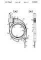
- FIG. 1is a section through a first embodiment of as device according to the present invention, taken on the line I--I of FIG. 2;
- FIG. 2is a view of the entire device taken in the direction of the arrow F of FIG. 1;
- FIG. 3is a top plan view of a second embodiment of a device according to the present invention.
- FIG. 4is a view of the entire device taken in the direction of the arrow G of FIG. 3.
- FIGS. 1 and 2show a branching device for fibre-optic cables, indicated overall by 10 and suitable for connection to units containing four optical fibres.
- optical fibres included in this embodimentis only indicative, and can be different.
- the branching device 10consists of two half-casings indicated by 11 and 12 respectively.
- the two half-casings 11 and 12can be joined together for example by through screws or by snap-insertion.
- the reference numeral 13indicates a multi-fibre unit containing four optical fibres.
- the optical fibres contained in the multi-fibre unit 13can either be combined into a tape or be contained in a tube.
- the multi-fibre unit 13enters an entry device consisting of a four-pole plug-in miniconnector indicated overall by 14.
- the miniconnector 14consists of two complementary parts, on the first of which, indicated by 15, the four fibres of the multi-fibre unit 13 surface.
- the two half-casings 11 and 12are shaped to form an annular cavity 18 when joined together.
- the four fibres 17 within the branching device 10extend along the annular cavity 18 until they reach four side-by-side single connectors indicated overall by 19.
- the width of the cavity 18is considerably greater than the width which would be strictly necessary to contain the separate optical fibres 17. Because of this, small length differences in the separate optical fibres 17 compared with the middle line through the cavity 18 can be well tolerated.
- any length variations in the optical fibres deriving from temperature changes in the environment in which the branching device 10 is locatedhave absolutely no influence. Because of the structure of the annular cavity 18, the separate optical fibres 17 can pass more than once about the cavity 18, to form a sort of fibre winding.
- the optical fibres 17can have a length at least greater than the length of the minimum development of the annular cavity 18.
- branching device 10of being able to contain in its interior optical fibres having a length greater than that strictly necessary for making the connection between the multiconnector 14 and the single connectors 19 is particularly advantageous in view of any later connections to be made to connectors and subsequent maintenance.
- connection between fibres and connectorsis made by stripping away the covering, then grinding and gluing.
- FIGS. 3 and 4show a second embodiment of the device of the present invention in which those parts in common with the embodiment of FIGS. 1 and 2 carry the same reference numerals.
- the multi-fibre unit 13enters an entry device 21 clamped between the half-casings 11 and 12 which form the casing of the branching device 10.
- the protective covering which resists traction on the multi-fibre unit 13is interrupted and rigidly fixed to the entry device 21, whereas the optical fibres continue for a convenient length within the branching device 10.
- connectionis preferably made either by a multiple miniconnector 22 or by other types of mechanical connector. In certain cases it can be convenient to make the connection between the fibres 17 and the fibres of the multi-fibre unit 13 by fusion-splicing.
- the two half-casings 11 and 12can be joined together for example by screws passing through threaded holes 24.
- This second embodimentretains all the advantages described with reference to the first embodiment, and is more simple and economical.
- the two half-casings 11 and 12 which form the main casing of the branching device 10can be constructed of any type of material.
- these half-casingscan be of plastics material to result in a device which is lightweight, strong and of low cost.
Landscapes
- Physics & Mathematics (AREA)
- General Physics & Mathematics (AREA)
- Optics & Photonics (AREA)
- Mechanical Coupling Of Light Guides (AREA)
- Light Guides In General And Applications Therefor (AREA)
Abstract
Description
This invention relates to a branching device for fibre-optic cables.
Fibre-optic cables are increasingly used in the most varied applications, especially in the telecommunications field. Where each cable contains a plurality of optical fibres, it is common practice to group the optical fibres into small separate groups within the cable, these groups normally containing from two to twelve optical fibres each.
The advantage obtained by such grouping is essentially that in this manner the fibre packing density is increased for equal external cable diameters.
By grouping the fibres into small groups each containing a small number of fibres, there is the further advantage of facilitating the recognition and ordered numbering of the individual optical fibres within the cable.
The methods most commonly used for achieving this grouping is to insert the groups of fibres into tubes or to glue the individual optical fibres into tapes of coplanar parallel fibres.
In any fibre-optic network in which such multi-fibre units are present there are points at which the individual optical fibres of these units are required to make abutting contact with single-fibre units.
For this purpose, devices are commonly used consisting of two half-casings which when joined together simply protect the points at which the connections between the multi-fibre units and the individual fibres are made.
The connections are commonly made by fusion-splicing or by fixed or movable miniconnectors.
However, because of the relative mechanical delicacy of optical fibres it is essential that the passage from multi-fibre units to single-fibre units is made in such a manner as to ensure absolute protection of each individual fibre.
In fibre-optic networks it is also frequently necessary, as in the case of any electrical cabling, to subsequently disturb the connections in order to make additions or modifications after installation.
It is therefore essential for an operator to be able not only to carry out ordinary maintenance but also to mount and replace connectors.
In addition, as there is a substantial difference between the thermal expansion coefficients of the optical fibre (of silica) and its protective covering (of plastics material) it is particularly important that cabling is arranged such that when temperature changes occur no dangerous mechanical stressing of the fibres results.
An object of the present invention is to provide a branching device for fibre-optic cables of the said type and for the stated applications which solves the problem of passing from multi-fibre units to single-fibre units, and also simplifies maintenance and connector mounting.
A further object of the present invention is to provide a branching device with which no problems arise in the arranging of the various parts deriving from dangerous mechanical stressing of the optical fibres when temperature changes occur.
These objects are attained by a branching device for fibre-optic cables, consisting essentially of two half-casings which can be joined together and contain means for connection to a multi-fibre/fibre-optic unit and means for connection to a plurality of single-fibre/fibre-optic units, characterized in that said half-casings are shaped to form a cavity arranged to contain a plurality of optical fibres, said cavity being of essentially annular shape and having a width greater than the thickness determined by said plurality of separate optical fibres within said device, said optical fibres within said branching device which connect together said means for connection to a multi-fibre/fibre-optic unit and said means for connection to a plurality of single-fibre/fibre-optic units having a length greater than the length of the minimum development of said annular cavity.
The structural and functional characteristics and advantages of a device according to the present invention will be more apparent from the description given hereinafter by way of non-limiting example with reference to the accompanying schematic drawings, in which:
FIG. 1 is a section through a first embodiment of as device according to the present invention, taken on the line I--I of FIG. 2;
FIG. 2 is a view of the entire device taken in the direction of the arrow F of FIG. 1;
FIG. 3 is a top plan view of a second embodiment of a device according to the present invention; and
FIG. 4 is a view of the entire device taken in the direction of the arrow G of FIG. 3.
FIGS. 1 and 2 show a branching device for fibre-optic cables, indicated overall by 10 and suitable for connection to units containing four optical fibres.
The number of optical fibres included in this embodiment is only indicative, and can be different.
Observing FIG. 2 it can be seen that thebranching device 10 consists of two half-casings indicated by 11 and 12 respectively. The two half-casings
Again with reference to FIGS. 1 and 2 thereference numeral 13 indicates a multi-fibre unit containing four optical fibres. The optical fibres contained in themulti-fibre unit 13 can either be combined into a tape or be contained in a tube.
Themulti-fibre unit 13 enters an entry device consisting of a four-pole plug-in miniconnector indicated overall by 14. Theminiconnector 14 consists of two complementary parts, on the first of which, indicated by 15, the four fibres of themulti-fibre unit 13 surface.
Four furtheroptical fibres 17 surface on the second 16 of the two parts into which theminiconnector 14 is divided, thepart 16 of theminiconnector 14 being clamped between the two half-casings branching device 10.
As can be seen from the sectional view of FIG. 1, the two half-casings annular cavity 18 when joined together.
The fourfibres 17 within thebranching device 10 extend along theannular cavity 18 until they reach four side-by-side single connectors indicated overall by 19.
It is apparent that in this manner, the four separateoptical fibres 17 are subjected only to the stress deriving from the shape of thecavity 18 through which they extend.
This stress, essentially of flexural type, is totally compatible with the proper preservation of the fibres and produces no attenuation increase in the signal transmitted by the fibres.
In this respect it is well known that damage to optical fibres and attenuation of the light signal which they transmit are greater the sharper the change in direction to which the optical fibres are subjected.
From FIG. 1 it can be seen that advantageously the width of thecavity 18 is considerably greater than the width which would be strictly necessary to contain the separateoptical fibres 17. Because of this, small length differences in the separateoptical fibres 17 compared with the middle line through thecavity 18 can be well tolerated.
Thus any length variations in the optical fibres deriving from temperature changes in the environment in which the branchingdevice 10 is located have absolutely no influence. Because of the structure of theannular cavity 18, the separateoptical fibres 17 can pass more than once about thecavity 18, to form a sort of fibre winding.
In particular, theoptical fibres 17 can have a length at least greater than the length of the minimum development of theannular cavity 18.
This possibility offered by the branchingdevice 10 of being able to contain in its interior optical fibres having a length greater than that strictly necessary for making the connection between themulticonnector 14 and thesingle connectors 19 is particularly advantageous in view of any later connections to be made to connectors and subsequent maintenance.
In this respect, in fibre-optic technology the connection between fibres and connectors is made by stripping away the covering, then grinding and gluing.
All these operations consume the end of the fibre, consequently reducing its useful length.
It is therefore immediately apparent that having a reserve of fibre inside the branching device itself for possible future connection to other connectors can be very useful.
From FIG. 1 it can be seen that instant fixing means 20 are provided on the half-casings branching device 10. The presence of the instant fixing means 20 and the particular external shape of the half-casings
Hence because of this thebranching device 10 allows complex units to be created, such as permutators, distribution frames and the like in which the cabling, although bulky, must be ordered, and able to be easily inspected, extended and if necessary replaced. The two half-casings
Alternatively, if no future work is to be done on the fibres and thebranching device 10 is of the disposable type, the two half-casings can be non-removably welded together.
FIGS. 3 and 4 show a second embodiment of the device of the present invention in which those parts in common with the embodiment of FIGS. 1 and 2 carry the same reference numerals. With reference to FIGS. 3 and 4 it can be seen that themulti-fibre unit 13 enters anentry device 21 clamped between the half-casings branching device 10.
The protective covering which resists traction on themulti-fibre unit 13 is interrupted and rigidly fixed to theentry device 21, whereas the optical fibres continue for a convenient length within thebranching device 10.
The optical fibres of themulti-fibre unit 13 are connected inside thecavity 18 to the separateoptical fibres 17 of thebranching device 10.
This connection is preferably made either by amultiple miniconnector 22 or by other types of mechanical connector. In certain cases it can be convenient to make the connection between thefibres 17 and the fibres of themulti-fibre unit 13 by fusion-splicing.
The two half-casings holes 24.
This second embodiment retains all the advantages described with reference to the first embodiment, and is more simple and economical.
However, as it is not provided with a plug-in connector this second embodiment does not have the same versatility and ease of connection to multi-fibre units as the first embodiment.
The two half-casings branching device 10 can be constructed of any type of material. Advantageously, these half-casings can be of plastics material to result in a device which is lightweight, strong and of low cost.
Claims (6)
1. A branching device for fibre-optic cables, consisting essentially of two half-casings which can be joined together and contain external means for connection to a multi-fibre/fibre-optic unit and means for connection to a plurality of single-fibre/fibre-optic units, characterized in that said half-casings are shaped to form a cavity arranged to contain a plurality of optical fibres, said cavity being of essentially annular shape and having a width greater than the thickness determined by said plurality of separate optical fibres within said device, said optical fibres within said branching device which connect together said means for connection to a multi-fibre/fibre-optic unit and said means for connection to a plurality of single-fibre/fibre-optic units having a length greater than the length of the minimum development of said annular cavity.
2. A device as claimed in claim 1, characterized in that said means for connection to said plurality of single-fibre/fibre-optic units are a plurality of single fibre-optic connectors.
3. A device as claimed in claim 1, characterized in that said means for connection to said multi-fibre/fibre-optic unit consist of a first and a second part of a multiple plug-in optical miniconnector, on said first part there surfacing the multiple fibres of said multi-fibre/fibre-optic unit, said second part being fixed to said branching device and being removably connectable to said first part.
4. A device as claims in claim 1, characterized in that said external means for connection to said multi-fibre/fibre-optic unit consist of an entry device to which a traction-resistant protective covering of said multi-fibre/fibre-optic unit can be fixed, said entry device being arranged to be clamped between said half-casings, and further consist of a multiple optical miniconnector contained within said cavity, said multiple optical miniconnector being arranged to connect within said branching device said separate optical fibres to the optical fibres of said multi-fibre/fibre-optic unit, which penetrate into said branching device through said entry device.
5. A device as claimed in claim 1, characterized in that instant fixing means are provided on said half-casings.
6. A device as claimed in claim 1, characterized in that said half-casings are constructed of plastics material.
Applications Claiming Priority (2)
| Application Number | Priority Date | Filing Date | Title |
|---|---|---|---|
| ITMI91A/001226 | 1991-05-06 | ||
| ITMI911226AIT1247307B (en) | 1991-05-06 | 1991-05-06 | BRANCH DEVICE FOR OPTICAL FIBER CABLES |
Publications (1)
| Publication Number | Publication Date |
|---|---|
| US5235665Atrue US5235665A (en) | 1993-08-10 |
Family
ID=11359842
Family Applications (1)
| Application Number | Title | Priority Date | Filing Date |
|---|---|---|---|
| US07/872,088Expired - LifetimeUS5235665A (en) | 1991-05-06 | 1992-04-22 | Branching device for fibre-optic cables |
Country Status (7)
| Country | Link |
|---|---|
| US (1) | US5235665A (en) |
| DE (1) | DE9206511U1 (en) |
| ES (1) | ES2037617B1 (en) |
| FR (1) | FR2676286A1 (en) |
| GB (1) | GB2255652B (en) |
| IT (1) | IT1247307B (en) |
| PT (1) | PT100408B (en) |
Cited By (51)
| Publication number | Priority date | Publication date | Assignee | Title |
|---|---|---|---|---|
| US5335304A (en)* | 1993-04-30 | 1994-08-02 | The United States Of America As Represented By The Secretary Of The Army | Connector distribution assembly for a fiber optic detector system |
| US5402515A (en)* | 1994-03-01 | 1995-03-28 | Minnesota Mining And Manufacturing Company | Fiber distribution frame system, cabinets, trays and fiber optic connector couplings |
| DE4412571C1 (en)* | 1994-04-13 | 1995-06-08 | Framatome Connectors Int | Combined optical waveguide metal cable plug-connector |
| US5457764A (en)* | 1992-04-30 | 1995-10-10 | Edera; Egisto | Diffusor device with extractable semiconnectors, integrated in a plastic card, for the termination of optical fiber ribbon cables |
| DE4443200C1 (en)* | 1994-12-05 | 1996-06-20 | Framatome Connectors Int | Combined optical fibre cable and metal cable plug connector |
| US5812727A (en)* | 1996-01-31 | 1998-09-22 | Asahi Kogaku Kogyo Kabushiki Kaisha | Holder for optical fibers in a scanning optical device |
| US5892870A (en)* | 1995-11-16 | 1999-04-06 | Fiber Connections Inc. | Fibre optic cable connector |
| US6130982A (en)* | 1997-04-30 | 2000-10-10 | Siemens Aktiengesellschaft | Cable sleeve for light waveguide cables |
| USD456009S1 (en) | 2001-03-12 | 2002-04-23 | Belkin Components | Multi port hub |
| US20020191942A1 (en)* | 2001-06-15 | 2002-12-19 | Griffiths Ian James | Connecting optical fibres |
| US20040264912A1 (en)* | 2003-06-28 | 2004-12-30 | Cooke Donald A. | Fiber transition segment for use in optical fiber hydrophone array |
| US20040264299A1 (en)* | 2003-06-28 | 2004-12-30 | Cooke Donald A. | Woven fiber protection cable assembly for use in optical fiber hydrophone array |
| US20040264906A1 (en)* | 2003-06-28 | 2004-12-30 | Cooke Donald A. | Fiber splice tray for use in optical fiber hydrophone array |
| US20040264298A1 (en)* | 2003-06-28 | 2004-12-30 | Cooke Donald A. | Termination assembly for use in optical fiber hydrophone array |
| US20040264893A1 (en)* | 2003-06-28 | 2004-12-30 | Cooke Donald A. | Optical fiber splice protection apparatus for use in optical fiber hydrophone array |
| US20050117857A1 (en)* | 2003-06-28 | 2005-06-02 | Cooke Donald A. | Mount for use in optical fiber hydrophone array |
| WO2005036232A3 (en)* | 2003-09-08 | 2005-07-14 | Adc Telecommunications Inc | Fiber optic cable and furcation module |
| US20050213921A1 (en)* | 2004-03-08 | 2005-09-29 | Mertesdorf Daniel R | Fiber access terminal |
| US20050249474A1 (en)* | 2004-05-05 | 2005-11-10 | Tan Chee S | Optical module for housing an optical component |
| US20060188210A1 (en)* | 2005-02-23 | 2006-08-24 | Adc Telecommunications, Inc. | Fiber optic furcation device including expansion chamber |
| US20070189694A1 (en)* | 2005-07-25 | 2007-08-16 | Tyco Electronics Corporation | Optical fiber cable termination apparatus |
| US20070237484A1 (en)* | 2006-04-05 | 2007-10-11 | Randy Reagan | Universal bracket for mounting a drop terminal |
| US7333708B2 (en) | 2004-01-27 | 2008-02-19 | Corning Cable Systems Llc | Multi-port optical connection terminal |
| USRE40358E1 (en) | 1998-07-27 | 2008-06-03 | Adc Telecommunications, Inc. | Outside plant fiber distribution apparatus and method |
| US20080175553A1 (en)* | 2006-12-27 | 2008-07-24 | Daniel Hendrickson | Axial overpackaging and routing apparatus for optical fiber power splitter devices |
| US20080232743A1 (en)* | 2007-03-23 | 2008-09-25 | Erik Gronvall | Drop terminal with anchor block for retaining a stub cable |
| US7489849B2 (en) | 2004-11-03 | 2009-02-10 | Adc Telecommunications, Inc. | Fiber drop terminal |
| US20090046985A1 (en)* | 2007-08-16 | 2009-02-19 | Erik Gronvall | Fiber Optic Enclosure Internal Cable Management |
| US20090060445A1 (en)* | 2007-08-27 | 2009-03-05 | Julian Mullaney | Fiber optic cable control clips and enclosure assemblies and methods incorporating the same |
| US7558458B2 (en) | 2007-03-08 | 2009-07-07 | Adc Telecommunications, Inc. | Universal bracket for mounting a drop terminal |
| US20090290844A1 (en)* | 2008-05-20 | 2009-11-26 | Julian Mullaney | Tap-off closure systems and methods for using the same |
| US7680388B2 (en) | 2004-11-03 | 2010-03-16 | Adc Telecommunications, Inc. | Methods for configuring and testing fiber drop terminals |
| US7740409B2 (en) | 2007-09-19 | 2010-06-22 | Corning Cable Systems Llc | Multi-port optical connection terminal |
| US7844158B2 (en) | 2007-10-09 | 2010-11-30 | Adc Telecommunications, Inc. | Mini drop terminal |
| US7903923B2 (en) | 2007-10-09 | 2011-03-08 | Adc Telecommunications, Inc. | Drop terminal releasable engagement mechanism |
| EP1939658A3 (en)* | 2006-12-27 | 2012-01-18 | Furukawa Electric North America Inc. (a Delaware Corporation) | Overpackaging and routing apparatus for optical fiber power splitter devices |
| EP2437090A1 (en) | 2010-10-04 | 2012-04-04 | Tyco Electronics Raychem BVBA | Cable connector tray, tray device, tray holder and method for connecting a connector with a mating connector |
| US20130089292A1 (en)* | 2011-10-07 | 2013-04-11 | Michael James Ott | Fiber optic cassette, system, and method |
| US8755663B2 (en) | 2010-10-28 | 2014-06-17 | Corning Cable Systems Llc | Impact resistant fiber optic enclosures and related methods |
| US8873926B2 (en) | 2012-04-26 | 2014-10-28 | Corning Cable Systems Llc | Fiber optic enclosures employing clamping assemblies for strain relief of cables, and related assemblies and methods |
| US8890050B2 (en) | 2011-11-21 | 2014-11-18 | Tyco Electronics Corporation | Photosensor circuits including a regulated power supply comprising a power circuit configured to provide a regulated power signal to a comparator of a pulse-width modulator |
| US9069151B2 (en) | 2011-10-26 | 2015-06-30 | Corning Cable Systems Llc | Composite cable breakout assembly |
| US9146374B2 (en) | 2012-09-28 | 2015-09-29 | Adc Telecommunications, Inc. | Rapid deployment packaging for optical fiber |
| US9223094B2 (en) | 2012-10-05 | 2015-12-29 | Tyco Electronics Nederland Bv | Flexible optical circuit, cassettes, and methods |
| US9435975B2 (en) | 2013-03-15 | 2016-09-06 | Commscope Technologies Llc | Modular high density telecommunications frame and chassis system |
| EP3919954A4 (en)* | 2020-04-07 | 2022-01-19 | Huawei Technologies Co., Ltd. | OPTICAL CABLE CONNECTOR DEVICE |
| US11372186B2 (en) | 2017-04-04 | 2022-06-28 | Commscope Technologies Llc | Optical splice and termination module |
| US11372165B2 (en) | 2011-09-12 | 2022-06-28 | Commscope Technologies Llc | Flexible lensed optical interconnect device for signal distribution |
| US11409068B2 (en) | 2017-10-02 | 2022-08-09 | Commscope Technologies Llc | Fiber optic circuit and preparation method |
| US11592628B2 (en) | 2012-09-28 | 2023-02-28 | Commscope Technologies Llc | Fiber optic cassette |
| US12339511B2 (en) | 2020-03-31 | 2025-06-24 | Commscope Technologies Llc | Fiber optic cable management systems and methods |
Families Citing this family (9)
| Publication number | Priority date | Publication date | Assignee | Title |
|---|---|---|---|---|
| GB2289955B (en)* | 1991-12-27 | 1996-07-17 | Seiko Giken Kk | Optical fibre light diverging/converging device having ferrules |
| FR2694642B1 (en)* | 1992-08-06 | 1996-04-19 | Pouyet Henri | DEVICE FOR CONNECTING AT LEAST ONE TRANSMISSION CABLE TO ELECTRONIC EQUIPMENT. |
| DE4226368A1 (en)* | 1992-08-09 | 1994-02-10 | Suhner Elektronik Gmbh | Transmission path for systems equipped with fiber optic cables |
| SE9301639L (en)* | 1993-05-12 | 1994-08-08 | Tykoflex Ab | Optical fiber cassette |
| GB9318632D0 (en)* | 1993-09-08 | 1993-10-27 | Raychem Sa Nv | Optical fibre organizer |
| GB2282457B (en)* | 1993-09-29 | 1996-10-02 | Pirelli General Plc | An assembly for use in connecting optical fibres |
| DE19531633A1 (en)* | 1995-08-28 | 1997-07-03 | Whitaker Corp | Optical data communication system |
| DE10148543C1 (en)* | 2001-10-01 | 2003-06-05 | Housecorn Gmbh | Distribution module for a network |
| DE102005052223B3 (en)* | 2005-10-30 | 2007-06-14 | Küpper, Lukas, Dipl.-Phys. | Temperature-resistant infrared probe |
Citations (6)
| Publication number | Priority date | Publication date | Assignee | Title |
|---|---|---|---|---|
| DE2721300A1 (en)* | 1977-05-12 | 1978-11-23 | Licentia Gmbh | Optical fibre cassette annular element - is disc with inner and outer lips for spaced stacking and sprung pins with locking shoulders |
| EP0281196A2 (en)* | 1987-03-03 | 1988-09-07 | Philips Patentverwaltung GmbH | Storing device for the supply length of at least one light wave guide |
| DE8905509U1 (en)* | 1989-05-02 | 1989-07-13 | Siemens AG, 1000 Berlin und 8000 München | Installation in a distribution board for receiving optical fibers |
| EP0408266A2 (en)* | 1989-07-11 | 1991-01-16 | BICC Public Limited Company | Termination system for optical fibres |
| US5067784A (en)* | 1990-11-19 | 1991-11-26 | George Debortoli | Connector holders |
| US5109467A (en)* | 1991-02-27 | 1992-04-28 | Keptel, Inc. | Interconnect cabinet for optical fibers |
Family Cites Families (4)
| Publication number | Priority date | Publication date | Assignee | Title |
|---|---|---|---|---|
| DE3530162A1 (en)* | 1985-08-23 | 1987-03-05 | Rose Walter Gmbh & Co Kg | DEVICE FOR THE SPLICING OF LIGHT-WAVE CORE |
| EP0250900A3 (en)* | 1986-06-25 | 1989-07-19 | Siemens Aktiengesellschaft | Distributor for telecommunication arrangements with light wave guides |
| US4846565A (en)* | 1988-06-10 | 1989-07-11 | Gte Products Corporation | Emergency preterminated cable apparatus |
| DE9017440U1 (en)* | 1990-12-24 | 1991-03-07 | Krupp Atlas Elektronik GmbH, 2800 Bremen | Multi-pin connector for fiber optic cable |
- 1991
- 1991-05-06ITITMI911226Apatent/IT1247307B/enactiveIP Right Grant
- 1992
- 1992-04-21GBGB9208539Apatent/GB2255652B/ennot_activeExpired - Fee Related
- 1992-04-21PTPT100408Apatent/PT100408B/ennot_activeIP Right Cessation
- 1992-04-22USUS07/872,088patent/US5235665A/ennot_activeExpired - Lifetime
- 1992-04-29DEDE9206511Upatent/DE9206511U1/ennot_activeExpired - Lifetime
- 1992-04-29ESES09200903Apatent/ES2037617B1/ennot_activeExpired - Lifetime
- 1992-05-05FRFR9205829Apatent/FR2676286A1/enactiveGranted
Patent Citations (6)
| Publication number | Priority date | Publication date | Assignee | Title |
|---|---|---|---|---|
| DE2721300A1 (en)* | 1977-05-12 | 1978-11-23 | Licentia Gmbh | Optical fibre cassette annular element - is disc with inner and outer lips for spaced stacking and sprung pins with locking shoulders |
| EP0281196A2 (en)* | 1987-03-03 | 1988-09-07 | Philips Patentverwaltung GmbH | Storing device for the supply length of at least one light wave guide |
| DE8905509U1 (en)* | 1989-05-02 | 1989-07-13 | Siemens AG, 1000 Berlin und 8000 München | Installation in a distribution board for receiving optical fibers |
| EP0408266A2 (en)* | 1989-07-11 | 1991-01-16 | BICC Public Limited Company | Termination system for optical fibres |
| US5067784A (en)* | 1990-11-19 | 1991-11-26 | George Debortoli | Connector holders |
| US5109467A (en)* | 1991-02-27 | 1992-04-28 | Keptel, Inc. | Interconnect cabinet for optical fibers |
Cited By (123)
| Publication number | Priority date | Publication date | Assignee | Title |
|---|---|---|---|---|
| US5457764A (en)* | 1992-04-30 | 1995-10-10 | Edera; Egisto | Diffusor device with extractable semiconnectors, integrated in a plastic card, for the termination of optical fiber ribbon cables |
| US5335304A (en)* | 1993-04-30 | 1994-08-02 | The United States Of America As Represented By The Secretary Of The Army | Connector distribution assembly for a fiber optic detector system |
| US5402515A (en)* | 1994-03-01 | 1995-03-28 | Minnesota Mining And Manufacturing Company | Fiber distribution frame system, cabinets, trays and fiber optic connector couplings |
| DE4412571C1 (en)* | 1994-04-13 | 1995-06-08 | Framatome Connectors Int | Combined optical waveguide metal cable plug-connector |
| US5570443A (en)* | 1994-04-13 | 1996-10-29 | Framatome Connectors International | Combined beam waveguide and metal cable plug connector |
| DE4443200C1 (en)* | 1994-12-05 | 1996-06-20 | Framatome Connectors Int | Combined optical fibre cable and metal cable plug connector |
| US5892870A (en)* | 1995-11-16 | 1999-04-06 | Fiber Connections Inc. | Fibre optic cable connector |
| US5812727A (en)* | 1996-01-31 | 1998-09-22 | Asahi Kogaku Kogyo Kabushiki Kaisha | Holder for optical fibers in a scanning optical device |
| US6130982A (en)* | 1997-04-30 | 2000-10-10 | Siemens Aktiengesellschaft | Cable sleeve for light waveguide cables |
| USRE40358E1 (en) | 1998-07-27 | 2008-06-03 | Adc Telecommunications, Inc. | Outside plant fiber distribution apparatus and method |
| USRE42258E1 (en) | 1998-07-27 | 2011-03-29 | Adc Telecommunications, Inc. | Outside plant fiber distribution apparatus and method |
| USRE41777E1 (en) | 1998-07-27 | 2010-09-28 | Adc Telecommunications, Inc. | Outside plant fiber distribution apparatus and method |
| USD456009S1 (en) | 2001-03-12 | 2002-04-23 | Belkin Components | Multi port hub |
| US20020191942A1 (en)* | 2001-06-15 | 2002-12-19 | Griffiths Ian James | Connecting optical fibres |
| US6810194B2 (en)* | 2001-06-15 | 2004-10-26 | Pirelli General Plc | Connecting optical fibers |
| US7027695B2 (en) | 2003-06-28 | 2006-04-11 | General Dynamics Advanced Information Systems, Inc. | Fiber transition segment for use in optical fiber hydrophone array |
| US20040264298A1 (en)* | 2003-06-28 | 2004-12-30 | Cooke Donald A. | Termination assembly for use in optical fiber hydrophone array |
| US6865334B2 (en) | 2003-06-28 | 2005-03-08 | General Dynamics Advanced Information Systems, Inc. | Termination assembly for use in optical fiber hydrophone array |
| US6870997B2 (en) | 2003-06-28 | 2005-03-22 | General Dynamics Advanced Information Systems, Inc. | Fiber splice tray for use in optical fiber hydrophone array |
| US6879545B2 (en) | 2003-06-28 | 2005-04-12 | General Dynamics Advanced Information Systems, Inc. | Woven fiber protection cable assembly for use in optical fiber hydrophone array |
| US20050117857A1 (en)* | 2003-06-28 | 2005-06-02 | Cooke Donald A. | Mount for use in optical fiber hydrophone array |
| US6904222B2 (en) | 2003-06-28 | 2005-06-07 | General Dynamics Advanced Information Systems, Inc. | Optical fiber splice protection apparatus for use in optical fiber hydrophone array |
| US20040264299A1 (en)* | 2003-06-28 | 2004-12-30 | Cooke Donald A. | Woven fiber protection cable assembly for use in optical fiber hydrophone array |
| US6934451B2 (en) | 2003-06-28 | 2005-08-23 | General Dynamics Advanced Information Systems, Inc. | Mount for use in optical fiber hydrophone array |
| US20040264906A1 (en)* | 2003-06-28 | 2004-12-30 | Cooke Donald A. | Fiber splice tray for use in optical fiber hydrophone array |
| US20040264893A1 (en)* | 2003-06-28 | 2004-12-30 | Cooke Donald A. | Optical fiber splice protection apparatus for use in optical fiber hydrophone array |
| US20040264912A1 (en)* | 2003-06-28 | 2004-12-30 | Cooke Donald A. | Fiber transition segment for use in optical fiber hydrophone array |
| CN102289045B (en)* | 2003-09-08 | 2014-11-12 | Adc电信公司 | Fiber optic cable and furcation module |
| CN1849538B (en)* | 2003-09-08 | 2013-05-01 | Adc电信公司 | Fiber Optic Cables and Breakout Modules |
| USRE47069E1 (en) | 2003-09-08 | 2018-10-02 | Commscope Technologies Llc | Fiber optic cable and furcation module |
| US20050185910A1 (en)* | 2003-09-08 | 2005-08-25 | Adc Telecommunications, Inc. | Fiber optic cable and furcation module |
| USRE49374E1 (en) | 2003-09-08 | 2023-01-17 | Commscope Technologies Llc | Fiber optic cable and furcation module |
| WO2005036232A3 (en)* | 2003-09-08 | 2005-07-14 | Adc Telecommunications Inc | Fiber optic cable and furcation module |
| US8311379B2 (en) | 2003-09-08 | 2012-11-13 | Adc Telecommunications, Inc. | Fiber optic cable and furcation module |
| US7653282B2 (en) | 2004-01-27 | 2010-01-26 | Corning Cable Systems Llc | Multi-port optical connection terminal |
| US7333708B2 (en) | 2004-01-27 | 2008-02-19 | Corning Cable Systems Llc | Multi-port optical connection terminal |
| US20050213921A1 (en)* | 2004-03-08 | 2005-09-29 | Mertesdorf Daniel R | Fiber access terminal |
| US20080131068A1 (en)* | 2004-03-08 | 2008-06-05 | Adc Telecommunications, Inc. | Fiber Access Terminal |
| US7397997B2 (en) | 2004-03-08 | 2008-07-08 | Adc Telecommunications, Inc. | Fiber access terminal |
| US7400815B2 (en) | 2004-03-08 | 2008-07-15 | Adc Telecommunications, Inc. | Fiber access terminal |
| US7292763B2 (en) | 2004-03-08 | 2007-11-06 | Adc Telecommunications, Inc. | Fiber access terminal |
| US20080226252A1 (en)* | 2004-03-08 | 2008-09-18 | Adc Telecommunications, Inc. | Fiber Access Terminal |
| USRE43762E1 (en) | 2004-03-08 | 2012-10-23 | Adc Telecommunications, Inc. | Fiber access terminal |
| US20080260344A1 (en)* | 2004-03-08 | 2008-10-23 | Adc Telecommunications, Inc. | Fiber access terminal |
| US20080260345A1 (en)* | 2004-03-08 | 2008-10-23 | Adc Telecommunications, Inc. | Fiber access terminal |
| US20070140642A1 (en)* | 2004-03-08 | 2007-06-21 | Adc Telecommunications, Inc. | Fiber access terminal |
| US7480437B2 (en) | 2004-03-08 | 2009-01-20 | Adc Telecommunications, Inc. | Fiber access terminal |
| US20090297112A1 (en)* | 2004-03-08 | 2009-12-03 | Adc Telecommunications, Inc. | Fiber access terminal |
| US8363999B2 (en) | 2004-03-08 | 2013-01-29 | Adc Telecommunications, Inc. | Fiber access terminal |
| US7941027B2 (en) | 2004-03-08 | 2011-05-10 | Adc Telecommunications, Inc. | Fiber access terminal |
| US7539387B2 (en) | 2004-03-08 | 2009-05-26 | Adc Telecommunications, Inc. | Fiber access terminal |
| US7539388B2 (en) | 2004-03-08 | 2009-05-26 | Adc Telecommunications, Inc. | Fiber access terminal |
| US7331722B2 (en)* | 2004-05-05 | 2008-02-19 | Avago Technologies Fiber Ip Pte Ltd | Optical module for housing an optical component |
| US20050249474A1 (en)* | 2004-05-05 | 2005-11-10 | Tan Chee S | Optical module for housing an optical component |
| US10890729B2 (en) | 2004-11-03 | 2021-01-12 | Commscope Technologies Llc | Fiber drop terminal and bracket |
| US9851522B2 (en) | 2004-11-03 | 2017-12-26 | Commscope Technologies Llc | Fiber drop terminal |
| US10042136B2 (en) | 2004-11-03 | 2018-08-07 | Commscope Technologies Llc | Fiber drop terminal |
| US7627222B2 (en) | 2004-11-03 | 2009-12-01 | Adc Telecommunications, Inc. | Fiber drop terminal |
| US7489849B2 (en) | 2004-11-03 | 2009-02-10 | Adc Telecommunications, Inc. | Fiber drop terminal |
| US7680388B2 (en) | 2004-11-03 | 2010-03-16 | Adc Telecommunications, Inc. | Methods for configuring and testing fiber drop terminals |
| US11567278B2 (en) | 2004-11-03 | 2023-01-31 | Commscope Technologies Llc | Fiber drop terminal |
| US12204157B2 (en) | 2004-11-03 | 2025-01-21 | Commscope Technologies Llc | Fiber drop terminal |
| US7805044B2 (en) | 2004-11-03 | 2010-09-28 | Adc Telecommunications, Inc. | Fiber drop terminal |
| US20090103871A1 (en)* | 2005-02-23 | 2009-04-23 | Adc Telecommunications, Inc. | Fiber optic furcation device including expansion chamber |
| US20060188210A1 (en)* | 2005-02-23 | 2006-08-24 | Adc Telecommunications, Inc. | Fiber optic furcation device including expansion chamber |
| US7505663B2 (en) | 2005-02-23 | 2009-03-17 | Adc Telecommunications, Inc. | Fiber optic furcation device including expansion chamber |
| US20070189694A1 (en)* | 2005-07-25 | 2007-08-16 | Tyco Electronics Corporation | Optical fiber cable termination apparatus |
| US7356237B2 (en)* | 2005-07-25 | 2008-04-08 | Tyco Electronics Corporation | Optical fiber cable termination apparatus |
| US8218935B2 (en) | 2006-04-05 | 2012-07-10 | Adc Telecommunications, Inc. | Universal bracket for mounting a drop terminal |
| US7844160B2 (en) | 2006-04-05 | 2010-11-30 | Adc Telecommunications, Inc. | Universal bracket for mounting a drop terminal |
| US7477824B2 (en) | 2006-04-05 | 2009-01-13 | Adc Telecommunications, Inc. | Universal bracket for mounting a drop terminal |
| US20110123166A1 (en)* | 2006-04-05 | 2011-05-26 | Adc Telecommunications, Inc. | Universal bracket for mounting a drop terminal |
| US20070237484A1 (en)* | 2006-04-05 | 2007-10-11 | Randy Reagan | Universal bracket for mounting a drop terminal |
| US20080175553A1 (en)* | 2006-12-27 | 2008-07-24 | Daniel Hendrickson | Axial overpackaging and routing apparatus for optical fiber power splitter devices |
| EP1939658A3 (en)* | 2006-12-27 | 2012-01-18 | Furukawa Electric North America Inc. (a Delaware Corporation) | Overpackaging and routing apparatus for optical fiber power splitter devices |
| US7558458B2 (en) | 2007-03-08 | 2009-07-07 | Adc Telecommunications, Inc. | Universal bracket for mounting a drop terminal |
| US20080232743A1 (en)* | 2007-03-23 | 2008-09-25 | Erik Gronvall | Drop terminal with anchor block for retaining a stub cable |
| US7512304B2 (en) | 2007-03-23 | 2009-03-31 | Adc Telecommunications, Inc. | Drop terminal with anchor block for retaining a stub cable |
| US20090046985A1 (en)* | 2007-08-16 | 2009-02-19 | Erik Gronvall | Fiber Optic Enclosure Internal Cable Management |
| US7738761B2 (en) | 2007-08-27 | 2010-06-15 | Tyco Electronics Corporation | Fiber optic cable control clips and enclosure assemblies and methods incorporating the same |
| US20110194830A1 (en)* | 2007-08-27 | 2011-08-11 | Tyco Electronics Corporation | Fiber optic cable control clips and enclosure assemblies and methods incorporating the same |
| US20100142909A1 (en)* | 2007-08-27 | 2010-06-10 | Tyco Electronics Corporation | Fiber optic cable control clips and enclosure assemblies and methods incorporating the same |
| US20090060445A1 (en)* | 2007-08-27 | 2009-03-05 | Julian Mullaney | Fiber optic cable control clips and enclosure assemblies and methods incorporating the same |
| US8135258B2 (en) | 2007-08-27 | 2012-03-13 | Tyco Electronics Corporation | Fiber optic cable control clips and enclosure assemblies and methods incorporating the same |
| US7953311B2 (en) | 2007-08-27 | 2011-05-31 | Tyco Electronics Corporation | Fiber optic cable control clips and enclosure assemblies and methods incorporating the same |
| US7740409B2 (en) | 2007-09-19 | 2010-06-22 | Corning Cable Systems Llc | Multi-port optical connection terminal |
| US7844158B2 (en) | 2007-10-09 | 2010-11-30 | Adc Telecommunications, Inc. | Mini drop terminal |
| US8213761B2 (en) | 2007-10-09 | 2012-07-03 | Adc Telecommunications | Mini drop terminal |
| US7903923B2 (en) | 2007-10-09 | 2011-03-08 | Adc Telecommunications, Inc. | Drop terminal releasable engagement mechanism |
| US20090290844A1 (en)* | 2008-05-20 | 2009-11-26 | Julian Mullaney | Tap-off closure systems and methods for using the same |
| US8005333B2 (en) | 2008-05-20 | 2011-08-23 | Tyco Electronics Corporation | Tap-off closure systems and methods for using the same |
| EP2437090A1 (en) | 2010-10-04 | 2012-04-04 | Tyco Electronics Raychem BVBA | Cable connector tray, tray device, tray holder and method for connecting a connector with a mating connector |
| WO2012045663A1 (en) | 2010-10-04 | 2012-04-12 | Tyco Electronics Raychem Bvba | Cable connector tray, tray device, tray holder and method for connecting a connector with a mating connector |
| US8755663B2 (en) | 2010-10-28 | 2014-06-17 | Corning Cable Systems Llc | Impact resistant fiber optic enclosures and related methods |
| US11372165B2 (en) | 2011-09-12 | 2022-06-28 | Commscope Technologies Llc | Flexible lensed optical interconnect device for signal distribution |
| US9535229B2 (en)* | 2011-10-07 | 2017-01-03 | Commscope Technologies Llc | Fiber optic cassette, system, and method |
| US11061197B2 (en)* | 2011-10-07 | 2021-07-13 | Commscope Technologies Llc | Fiber optic cassette, system, and method |
| US20130089292A1 (en)* | 2011-10-07 | 2013-04-11 | Michael James Ott | Fiber optic cassette, system, and method |
| US11561356B2 (en) | 2011-10-07 | 2023-01-24 | Commscope Technologies Llc | Fiber optic cassette, system, and method |
| US9069151B2 (en) | 2011-10-26 | 2015-06-30 | Corning Cable Systems Llc | Composite cable breakout assembly |
| US8890050B2 (en) | 2011-11-21 | 2014-11-18 | Tyco Electronics Corporation | Photosensor circuits including a regulated power supply comprising a power circuit configured to provide a regulated power signal to a comparator of a pulse-width modulator |
| US8873926B2 (en) | 2012-04-26 | 2014-10-28 | Corning Cable Systems Llc | Fiber optic enclosures employing clamping assemblies for strain relief of cables, and related assemblies and methods |
| US9927591B2 (en) | 2012-09-28 | 2018-03-27 | Commscope Technologies Llc | Rapid deployment packaging for optical fiber |
| US11592628B2 (en) | 2012-09-28 | 2023-02-28 | Commscope Technologies Llc | Fiber optic cassette |
| US9470869B2 (en) | 2012-09-28 | 2016-10-18 | Commscope Technologies Llc | Rapid deployment packaging for optical fiber |
| US9146374B2 (en) | 2012-09-28 | 2015-09-29 | Adc Telecommunications, Inc. | Rapid deployment packaging for optical fiber |
| US11573389B2 (en) | 2012-10-05 | 2023-02-07 | Commscope Asia Holdings B.V. | Flexible optical circuit, cassettes, and methods |
| US10317638B2 (en) | 2012-10-05 | 2019-06-11 | Commscope Asia Holdings B.V. | Flexible optical circuit, cassettes, and methods |
| US9874711B2 (en) | 2012-10-05 | 2018-01-23 | Commscope Asia Holdings B.V. | Flexible optical circuit, cassettes, and methods |
| US10955633B2 (en) | 2012-10-05 | 2021-03-23 | Commscope Asia Holdings B.V. | Flexible optical circuit, cassettes, and methods |
| US12130487B2 (en) | 2012-10-05 | 2024-10-29 | Commscope Asia Holdings B.V. | Flexible optical circuit, cassettes, and methods |
| US9223094B2 (en) | 2012-10-05 | 2015-12-29 | Tyco Electronics Nederland Bv | Flexible optical circuit, cassettes, and methods |
| US10473875B2 (en) | 2013-03-15 | 2019-11-12 | Commscope Technologies Llc | Modular high density telecommunications frame and chassis system |
| US9435975B2 (en) | 2013-03-15 | 2016-09-06 | Commscope Technologies Llc | Modular high density telecommunications frame and chassis system |
| US9952398B2 (en) | 2013-03-15 | 2018-04-24 | Commscope Technologies Llc | Modular high density telecommunications frame and chassis system |
| US11860433B2 (en) | 2017-04-04 | 2024-01-02 | Commscope Technologies Llc | Optical splice and termination module |
| US11372186B2 (en) | 2017-04-04 | 2022-06-28 | Commscope Technologies Llc | Optical splice and termination module |
| US11609400B2 (en) | 2017-10-02 | 2023-03-21 | Commscope Technologies Llc | Fiber optic circuit and preparation method |
| US11409068B2 (en) | 2017-10-02 | 2022-08-09 | Commscope Technologies Llc | Fiber optic circuit and preparation method |
| US12276858B2 (en) | 2017-10-02 | 2025-04-15 | Commscope Technologies Llc | Fiber optic circuit and preparation method |
| US12339511B2 (en) | 2020-03-31 | 2025-06-24 | Commscope Technologies Llc | Fiber optic cable management systems and methods |
| EP3919954A4 (en)* | 2020-04-07 | 2022-01-19 | Huawei Technologies Co., Ltd. | OPTICAL CABLE CONNECTOR DEVICE |
| EP4403969A3 (en)* | 2020-04-07 | 2024-10-23 | Huawei Technologies Co., Ltd. | Optical cable connection apparatus |
Also Published As
| Publication number | Publication date |
|---|---|
| GB9208539D0 (en) | 1992-06-03 |
| GB2255652A (en) | 1992-11-11 |
| PT100408B (en) | 1999-07-30 |
| ITMI911226A1 (en) | 1992-11-06 |
| PT100408A (en) | 1994-04-29 |
| IT1247307B (en) | 1994-12-12 |
| ES2037617B1 (en) | 1996-08-01 |
| ES2037617A2 (en) | 1993-06-16 |
| FR2676286A1 (en) | 1992-11-13 |
| DE9206511U1 (en) | 1992-07-16 |
| GB2255652B (en) | 1994-08-17 |
| FR2676286B1 (en) | 1995-01-06 |
| ITMI911226A0 (en) | 1991-05-06 |
| ES2037617R (en) | 1996-01-16 |
Similar Documents
| Publication | Publication Date | Title |
|---|---|---|
| US5235665A (en) | Branching device for fibre-optic cables | |
| US11438070B2 (en) | Methods, systems, and devices for integrating wireless technology into a fiber optic network | |
| CN102449522B (en) | For the port mapping of optic fibre connector of connecting | |
| US7630610B2 (en) | Loop back plug with protective dust cap | |
| CA2407860A1 (en) | Optical assembly | |
| EP0216470A3 (en) | Connecting section for optical fiber cable | |
| EP2558898B1 (en) | Network device with drop port adapter connector and pass through-port multifibre adapter | |
| EP3602160A1 (en) | Telecommunications system and methods | |
| US20190204510A1 (en) | Optical interconnect apparatus | |
| EP1285299B1 (en) | Optical assembly | |
| KR200230008Y1 (en) | Ribbon Multicore Fiber Optic Connector | |
| US7197223B2 (en) | Glass fiber monitoring module | |
| US20100104247A1 (en) | Optical access network system | |
| Grimes et al. | Packaging of optoelectronics and passive optics in a high capacity transmission terminal | |
| KR200237989Y1 (en) | Fiber-optic cable splice tray of connect case | |
| Joly | Optical interfaces in cable networks | |
| KR20080095089A (en) | Optical cable support | |
| Ostlund | Survey of fiber optic connectors and cables | |
| Hornung | Component Design for Passive Optical Networks |
Legal Events
| Date | Code | Title | Description |
|---|---|---|---|
| AS | Assignment | Owner name:SIRTI S.P.A., ITALY Free format text:ASSIGNMENT OF ASSIGNORS INTEREST.;ASSIGNORS:MARCHESI, FRANCO;ZINI, GIANCARLO;CRICO, STEFANO;REEL/FRAME:006093/0483 Effective date:19920413 | |
| STCF | Information on status: patent grant | Free format text:PATENTED CASE | |
| FPAY | Fee payment | Year of fee payment:4 | |
| REMI | Maintenance fee reminder mailed | ||
| FPAY | Fee payment | Year of fee payment:8 | |
| FPAY | Fee payment | Year of fee payment:12 | |
| AS | Assignment | Owner name:SIRTI S.P.A., ITALY Free format text:CHANGE OF ADDRESS;ASSIGNOR:SIRTI S.P.A;REEL/FRAME:018679/0692 Effective date:20061016 | |
| AS | Assignment | Owner name:SISTEMI TECNOLOGICI S.P.A., ITALY Free format text:MERGER;ASSIGNOR:SIRTI S.P.A.;REEL/FRAME:018688/0661 Effective date:20061016 | |
| AS | Assignment | Owner name:SIRTI S.P.A, ITALY Free format text:CHANGE OF NAME;ASSIGNOR:SISTEMI TECNOLOGICI S.P.A;REEL/FRAME:018688/0730 Effective date:20061016 |