US5235326A - Multi-mode identification system - Google Patents
Multi-mode identification systemDownload PDFInfo
- Publication number
- US5235326A US5235326AUS07/746,129US74612991AUS5235326AUS 5235326 AUS5235326 AUS 5235326AUS 74612991 AUS74612991 AUS 74612991AUS 5235326 AUS5235326 AUS 5235326A
- Authority
- US
- United States
- Prior art keywords
- information
- tag
- magnetic field
- power
- reader
- Prior art date
- Legal status (The legal status is an assumption and is not a legal conclusion. Google has not performed a legal analysis and makes no representation as to the accuracy of the status listed.)
- Expired - Lifetime
Links
Images


Classifications
- G—PHYSICS
- G06—COMPUTING OR CALCULATING; COUNTING
- G06K—GRAPHICAL DATA READING; PRESENTATION OF DATA; RECORD CARRIERS; HANDLING RECORD CARRIERS
- G06K7/00—Methods or arrangements for sensing record carriers, e.g. for reading patterns
- G06K7/10—Methods or arrangements for sensing record carriers, e.g. for reading patterns by electromagnetic radiation, e.g. optical sensing; by corpuscular radiation
- G06K7/10009—Methods or arrangements for sensing record carriers, e.g. for reading patterns by electromagnetic radiation, e.g. optical sensing; by corpuscular radiation sensing by radiation using wavelengths larger than 0.1 mm, e.g. radio-waves or microwaves
- G06K7/10297—Methods or arrangements for sensing record carriers, e.g. for reading patterns by electromagnetic radiation, e.g. optical sensing; by corpuscular radiation sensing by radiation using wavelengths larger than 0.1 mm, e.g. radio-waves or microwaves arrangements for handling protocols designed for non-contact record carriers such as RFIDs NFCs, e.g. ISO/IEC 14443 and 18092
- G—PHYSICS
- G01—MEASURING; TESTING
- G01V—GEOPHYSICS; GRAVITATIONAL MEASUREMENTS; DETECTING MASSES OR OBJECTS; TAGS
- G01V15/00—Tags attached to, or associated with, an object, in order to enable detection of the object
- G—PHYSICS
- G06—COMPUTING OR CALCULATING; COUNTING
- G06K—GRAPHICAL DATA READING; PRESENTATION OF DATA; RECORD CARRIERS; HANDLING RECORD CARRIERS
- G06K19/00—Record carriers for use with machines and with at least a part designed to carry digital markings
- G06K19/06—Record carriers for use with machines and with at least a part designed to carry digital markings characterised by the kind of the digital marking, e.g. shape, nature, code
- G06K19/067—Record carriers with conductive marks, printed circuits or semiconductor circuit elements, e.g. credit or identity cards also with resonating or responding marks without active components
- G06K19/07—Record carriers with conductive marks, printed circuits or semiconductor circuit elements, e.g. credit or identity cards also with resonating or responding marks without active components with integrated circuit chips
- G06K19/0723—Record carriers with conductive marks, printed circuits or semiconductor circuit elements, e.g. credit or identity cards also with resonating or responding marks without active components with integrated circuit chips the record carrier comprising an arrangement for non-contact communication, e.g. wireless communication circuits on transponder cards, non-contact smart cards or RFIDs
- G—PHYSICS
- G06—COMPUTING OR CALCULATING; COUNTING
- G06K—GRAPHICAL DATA READING; PRESENTATION OF DATA; RECORD CARRIERS; HANDLING RECORD CARRIERS
- G06K7/00—Methods or arrangements for sensing record carriers, e.g. for reading patterns
- G06K7/0008—General problems related to the reading of electronic memory record carriers, independent of its reading method, e.g. power transfer
Definitions
- This inventionrelates to cooperative identification systems (which had their electronic beginnings in World War II as Identification--Friend or Foe Systems) in which the identifying agency and the object to be identified cooperate in the identification process according to a prearranged scheme. More specifically, the invention relates to systems consisting generically of an interrogator-responsor (or "reader”) inductively coupled to a transponder (or "tag”) where the reader is associated with the identifying agency and the tag is associated with the object to be identified.
- an interrogator-responsoror "reader”
- transponderor "tag”
- Such systemsare being used or have the potential of being used for identifying fish, birds, animals, or inanimate objects such as credit cards.
- Some of the more interesting applicationsinvolve objects of small size which means that the transponder must be minute.
- it is desirable to permanently attach the tag to the objectwhich means implantation of the device in the tissues of living things and somewhere beneath the surfaces of inanimate objects.
- implantation of the tag within the objectforecloses the use of conventional power sources for powering the tag. Sunlight will usually not penetrate the surface of the object. Chemical sources such as batteries wear out and cannot easily be replaced. Radioactive sources might present unacceptable risks to the object subject to identification.
- the tagIn order to minimize the trauma associated with implanting the tag in living creatures and also as a matter of convenience and utility, the tag should be small enough to be implanted by means of a syringe-type instrument rather than by surgery. This approach has been proved out in present-day systems and is likely to continue to be the implantation procedure of choice in the future.
- the size of present-day tagsare reasonable insofar as the larger specimens are concerned. However, size reduction is necessary if the tags are to be used with the smaller animals, birds, and fish.
- the multi-mode identification systemis comprised of readers and tags wherein a reader in the proximity of and inductively coupled to a tag may interrogate and obtain a response from the tag in accordance with a specified process if the tag belongs to a certain class of tags.
- the responseconsists of an identification code unique to the tag together with data supplied by sensors incorporated within the tag.
- the tagsare comprised of capacitors, inductors, transistors, and possibly other solid-state devices packaged in forms adapted for attachment to or implantation in animate or inanimate objects.
- the basic configuration of a tagconsists of a multi-turn coiled conductor that develops a voltage across its terminals in response to a reversing interrogating magnetic field produced by a reader and passing through the coil; a capacitor in parallel with the coil, the combination being resonant at some interrogating magnetic field frequency; an AC-to-DC converter bridged across the resonant circuit which extracts AC power from the magnetic field and delivers DC power to all of the tag circuits; a controller (or microprocessor) which controls all operations in the tag; a clock generator which utilizes the induced signal across the resonant circuit to generate all required clock signals for tag operations; a threshold detector which provides a reset signal to the controller when the AC-to-DC converter output voltage reaches a level sufficient to operate all of the tag circuitry; non-volatile memory, accessible to the
- the tagis physically comprised of a semiconductor chip incorporating the devices and circuitry of the tag including the tuning capacitor and a multi-turn coiled conductor which is attached to the semiconductor chip, the combination being sealed within a glass tube or other appropriate container.
- the portable version of the readeris adapted for operation by batteries.
- the readeris adapted for operation from alternating current power sources.
- a multi-turn coiled conductor in the readerprovides the means for inductively coupling the reader to the coil in a tag when the two units are in proximity of one another.
- Capacitorsare placed in series with the coil to create a circuit resonant at the same frequency as the resonant circuit in the tag to be read. Provision is made for the near-instantaneous selection of capacitance or coil inductance values so that the resonant frequency of the reader can be selected to match the resonant frequency of the tag.
- the reader resonant circuitis driven at the resonant frequency by a balanced double-ended coil driver which is supplied with a periodic signal of appropriate frequency by a clock generator.
- the clock generatoralso supplies all timing signals required in the operation of the reader.
- the voltage across the reader coilis modulated in amplitude according to the loading pattern applied to the tag resonant circuit when the tag responds to an interrogation from the reader.
- This variation in amplitudewhich is a measure of the power absorbed by the tag from the reversing magnetic field, is detected by means of an envelope detector.
- the signal-to-noise ratio of the envelope detector signalis maximized by appropriate filtering and the signal is then digitized by an A/D converter.
- the digitized envelope detector signalis supplied to a microprocessor which extracts the data transmitted to the reader by the tag.
- a notch filter tuned to the driving frequency of the reader coilis substituted for the envelope detector and the output signal from the notch filter is digitized and supplied to the microprocessor which extracts the data from the signal.
- the purpose of the notch filteris to suppress the huge driving signal that is present in the coil signal thereby reducing the dynamic range required of the A/D converter.
- the microprocessorinterprets the data and places it in a form suitable for display to the user.
- the microprocessoralso supplies audio signals and/or artificial speech that are intended to inform and guide the user in his use of the reader.
- the readercan be configured to operate in a variety of modes by means of hardware and firmware switches actuated by mode control data contained in a read-only memory within the reader.
- mode control datacontained in a read-only memory within the reader.
- the parameters that can be controlled by mode control dataare operating frequency, demodulation protocols, error control protocols, tag classes, and search sequencing among tag classes.
- the tag classis a group of tags that the reader is enabled to recognize.
- a tag class codemay identify tags of a particular design, tags from a particular manufacturer, tags utilized by particular user groups, tags utilized for the identification of particular species of objects, etc.
- an operating mode which specifies a single tag classmay restrict the reader to recognizing responses from tags of a particular design from a certain manufacturer that are utilized by a particular user group for the identification of particular species.
- the mode control datamay specify more than one tag class in which case the reader is permitted to recognize an expanded population of tags. If the mode control data specifies more than one tag class, then the reader either interrogates all classes simultaneously or proceeds from one class to the next in sequence until all of the classes have been interrogated, at which point the interrogation process repeats.
- the readerIn searching an object for a tag, the reader is moved over the surface of the object until either a tag response is received or the surface of the object where the tag might be located has been completely scanned.
- the determination by the reader that a tag belonging to an enabled class is respondingoccurs within a specific period of time (the detection time) after the reader begins to transmit. If the reader does not obtain a response within the detection time, the reader turns off so as to conserve battery power.
- the readerturns on again and performs another interrogation after a second specific period of time (the repositioning time) has elapsed. This repositioning time is long enough to permit the reader to be moved to a new location on the surface of the object.
- This power-on/power-off processis a very effective means for conserving battery power in the reader.
- One object of the inventionis to provide an identification system comprising readers and tags wherein a reader is restricted to recognizing only certain classes of tags.
- a second object of the inventionis to provide a general-purpose reader that can produce responses from a variety of tags of different designs and that can recognize and decode the responses from these differently-designed tags.
- a third object of the inventionis to enable the reader to read the tag message on the basis of a one-time transmission thereby permitting the reader to conserve battery power by turning itself off immediately after the one-time transmission. This object is achieved by delaying the tag response until the reader is ready to receive thereby assuring that the reader does not begin reading the data midway through the message transmission.
- a fourth object of the inventionis to integrate the coil, capacitor, and circuitry that comprise a tag to the highest degree that the technology will allow.
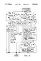
- FIG. 1is a functional block diagram of the multi-mode identification system including reader and tag.
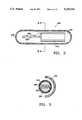
- FIG. 2is a side view of a tag designed for implantation with part of the enclosing container cut away.
- FIG. 3is a cross-sectional view of a tag designed for implantation in a plane transverse to the longitudinal axis of the tag.
- FIG. 4Ais the flow diagram of the 4 Times "Mark” Frequency Interrupt Routine that is performed by the microprocessor in the reader.
- FIG. 4Bis the flow diagram of the 4 Times "Mark" Frequency Delayed Interrupt Routine that is performed by the microprocessor in the reader.
- FIG. 5Ais the flow diagram of the 4 Times "Space" Frequency Interrupt Routine that is performed by the microprocessor in the reader.
- FIG. 5Bis the flow diagram of the 4 Times "Space" Frequency Delayed Interrupt Routine that is performed by the microprocessor in the reader.
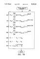
- FIG. 6Ais the flow diagram of the "Mark" Frequency Interrupt Routine that is performed by the microprocessor in a first embodiment of the reader.
- FIG. 6Bis the flow diagram of the "Mark" Frequency Interrupt Routine that is performed by the microprocessor in a second embodiment of the reader.
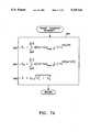
- FIG. 7Ais the flow diagram of the "Space" Frequency Interrupt Routine that is performed by the microprocessor in a first embodiment of the reader.
- FIG. 7Bis the flow diagram of the "Space" Frequency Interrupt Routine that is performed by the microprocessor in a second embodiment of the reader.
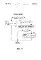
- FIG. 8is the flow diagram of the Calibrate Routine that is performed by the microprocessor in the reader.
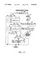
- FIG. 9is the flow diagram of the Operate Routine that is performed by the microprocessor in the reader.
- FIG. 10is the flow diagram of the Bit Rate (Data) Interrupt Routine that is performed by the microprocessor in the reader.
- FIG. 11is the flow diagram of the Message Recovery Routine that is performed by the microprocessor in the reader.
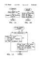
- FIG. 12is the flow diagram of the Message Processing Routine that is performed by the microprocessor in the reader.
- FIG. 13is the flow diagram of the Power-On Routine that is performed by the microprocessor in the reader.
- FIG. 14is the flow diagram of the T 1 Interrupt Routine that is performed by the microprocessor in the reader.
- FIG. 15is the flow diagram of the Bit Rate (Control) Interrupt Routine that is performed by the microprocessor in the reader.
- FIG. 16is the flow diagram of the Coil-Off Interrupt Routine that is performed by the microprocessor in the reader.
- the functional block diagram for an inductively-coupled reader 100 and tag 200are shown in FIG. 1.
- the reader 100interrogates the tag 200 by generating a reversing magnetic field 10 by means of the wound wire coil 110.
- the coil 110in series with either capacitor pair 120 or 125, selectable by means of SPDT switch pair 130, is driven by the double-ended balanced coil driver 135 with a periodic signal of appropriate frequency supplied by the clock generator 140.
- the driving frequencyis in the range from 100 kHz to 400 kHz.
- the clock generator 140is comprised of a crystal-controlled oscillator and divider chains of ordinary design.
- the oscillator frequencyis chosen such that all required driving frequencies can be obtained by integer divisions. Further integer divisions of each driving frequency provide square-wave clocking signals having the following frequencies: 4 times "mark” frequency; 4 times "space” frequency; “mark” frequency; "space” frequency; bit rate (data); and bit rate (control).
- the clocking signalsare obtained in such a way that the low-to-high transitions of all signals except the bit rate (control) signal coincide at particular instants of time.
- the low-to-high transition of the bit rate (control) signalprecedes that of the bit rate (data) signal by at least one cycle of the driving frequency.
- the clock generator 140includes the duty cycle timer which generates a square-wave timing signal that causes the reader coil 110 to be energized when the signal is high.
- the signalremains high for a time long enough to receive the information to be communicated by a tag on the particular driving frequency being used.
- the signalremains low for a time long enough for the reader 100 to be moved to a new reading position.
- the duty cycle timerproduces the "coil-off" interrupt signal to the microprocessor 170 when the timing signal it generates goes low.
- the purpose of operating the reader coil 110 with a duty cycleis to conserve battery power and achieve longer operating periods between battery rechargings or replacements.
- the duty cycle timeris set to low by the microprocessor 170 whenever the microprocessor recognizes a condition that indicates failure of the read process.
- the duty cycle timerturns on only when the reader power switch is on and the user-activated "read” trigger switch 142 is closed. Releasing the "read” trigger does not disable the duty cycle timer until the normal transition from high to low occurs.
- Time Tis maintained in the clock generator 140 by a counter that counts cycles of the driving frequency when the duty cycle timer signal is high.
- the counteris reset each time the duty cycle timer signal goes from high to low.
- the T countercan be accessed by the microprocessor 170 by means of the control bus 187 and data bus 190.
- the T countersupplies an interrupt signal to the microprocessor 170 when T equals T 1 where T 1 is the time required for the reader coil voltage to approach within say 0.1% of its steady-state voltage. When the T 1 interrupt occurs, signal processing in the reader begins.
- a typical design for balanced drivers suitable for driving the coil 110 and capacitors 120 or 125is commercially-available integrated circuit SI9950DY which comprises a complementary pair of power metal oxide silicon field effect transistors (power MOSFETS).
- SI9950DYwhich comprises a complementary pair of power metal oxide silicon field effect transistors (power MOSFETS).
- the two capacitors comprising each coil pairhave equal capacitances, the capacitance being chosen so that the combination of the coil and capacitor pair constitutes a series resonant circuit at a desired driving frequency.
- the tag 200when in the proximity of and inductively-coupled to the reader 100, extracts power from the alternating magnetic field 10 established by the reader coil 110 by means of the multi-turn coiled conductor 210 in parallel with the capacitor 220, the combination constituting a resonant circuit at one of the reader's driving frequencies.
- the variable load 230is connected across the coil-capacitor combination thereby providing a means for varying the load on the balanced coil driver 135 in the reader 100 resulting from the inductive coupling of the reader and tag coils.
- the variable load 230is resistive in the preferred embodiment thereby achieving the greatest possible effectiveness in absorbing power from the reversing magnetic field and in communicating with the reader.
- Other less desirable embodimentscould use loads that are inductive, capacitive, or some combination of inductive, capacitive, and resistive.
- the communication capability of the reader 100 and the tag 200are critically dependent on the characteristics of the reader coil 110 and the tag coil 210.
- the number of turns for the reader coilshould be as large as possible so that the magnetic field created by the reader coil is a large as possible.
- the resistance of the reader coil 110(proportional to the number of turns) must not become so large as to be a substantial mismatch to the driving impedance and thereby impede the transfer of power to the tag.
- the preferred embodiment of the reader coilis wound on an oval plastic core approximately 45/8 inches long by 33/4 inches wide.
- the coilis wound with 90 to 100 turns of 28-gauge wire yielding a coil with approximate inductance of 2.3 mH and approximate resistance of 7.6 ohms.
- the number of turns on the tag coil 210also should be as large as possible in order to maximize the inductively-generated voltage across the coil. Again caution must be exercised in choosing the number of turns so that the power transfer between reader and tag is not adversely affected.
- the alternating voltage appearing across the coil 210 as a result of being inductively coupled to the reader coil 110is converted to direct current by means of the AC/DC converter and voltage regulator 235 which supplies all of the power required by the tag circuitry.
- the alternating voltage appearing across the coil 210provides a reference frequency for the clock generator 240 which supplies all of the clocking signals required by the tag circuitry.
- Another embodimentutilizes the alternating coil voltage to stabilize a voltage-controlled oscillator which would then act as the source for all clocking signals.
- the controller 245controls all of the operations performed by the tag circuitry.
- a clock signal for the controller 245is supplied by the clock generator 240.
- the threshold detector 250produces a signal when the voltage from the AC/DC converter and voltage regulator 235 reaches the level required for reliable operation of the tag circuitry.
- the signal from the threshold detector 250serves to reset the controller which waits for a predetermined period of time (measured by a clock cycle counter in the controller) and then initiates the transmission of information to the reader.
- the transmission delaymay also be accomplished with a simple analog timing circuit.
- the predetermined transmission delayis for the purpose of allowing the transient associated with the application of a voltage to the reader resonant circuit 110, 120/125 to die down to the point where power absorption by the tag can be detected by the reader.
- the readeris thereby able to extract information from the power absorption signal as soon as the tag begins transmitting making it unnecessary for the reader magnetic field to be energized longer than the duration of a single message transmission and to be turned off quickly
- the threshold detectoris a simple circuit that uses a Zener diode as a reference voltage.
- a messageis transmitted by the controller by applying a two-level signal corresponding to a message bit pattern to the variable load 230.
- a messageconsists of a 10-bit synchronization code, a 24-bit tag class code, a 56-bit identification code, a 16-bit error-detecting code based on the CCITT standard 16 bit checksum, and finally a predetermined number of 8-bit sensor data words.
- the checksumpermits up to 16 bit errors in that portion of the message consisting of the tag class code and the identification code to be detected.
- Each of the sensor wordscarries its own parity bit thereby permitting single-error detection in each of the sensor data words.
- the controllerretrieves for transmission all but the sensor data portion of the message from the non-volatile memory 255.
- the controllerobtains the sensor data by causing the sensor selector 260 to connect the A/D converter 265 sequentially first to temperature sensor 270 and then to a PH sensor 275 or other desired sensor.
- variable load 230In the absence of a message transmission from the controller 245, the variable load 230 is dormant and does not appreciably load the resonant circuit 210, 220.
- the controllertransmits a message over line 238 to the variable load 230, the variable load applies a load to the resonant circuit 210, 220 in accordance with a frequency-shift-keying (FSK) technique.
- FSKfrequency-shift-keying
- the "space” frequency signalcauses the load to be turned on or off depending on the high and low states of the "space” frequency signal.
- the "mark” and “space” frequency square-wave signalsare derived from the reader driving frequency and supplied by the clock generator 240 to the variable load 230 over lines 242.
- the readermay advantageously extract the information from the power absorption signal by means of a coherent demodulation technique thereby realizing the increased communication efficiency of coherent frequency-shift keying (CFSK) as compared to non-coherent frequency shift keying (NCFSK).
- CFSKcoherent frequency-shift keying
- NCFSKnon-coherent frequency shift keying
- the "mark” and “space” frequenciesare chosen small enough that the sidebands resulting from the amplitude modulation of the driving-frequency signal are not attenuated by more than say 3 dB with respect to the driving frequency by the reader resonant circuit 110, 120/125.
- the spacing of the "mark” and “space” frequenciesshould ideally be an integer times the bit rate where the integer is preferably equal to or greater than two. For a driving frequency of 400 kHz and a bit rate of 5 kHz, typical values for the "mark” and “space” frequencies are 50 kHz and 40 kHz respectively. Note that the difference 10 kHz is equal to the integer 2 times the bit rate.
- on-off-keyingcould be used whereby the variable load 230 turns the load off when a "0" is transmitted and turns the load on and off when a "1" is transmitted (or vice versa) in accordance with whether a square wave of predetermined frequency supplied by the clock 240 is high or low.
- Phase-shift-keyingin either the fully-coherent (CPSK) or differentially-coherent (DCPSK) versions could also be used. Coherent phase-shift-keying would result if the variable load 230 turned the load on or off in accordance with whether the square wave described above was high or low respectively when a "0" was transmitted and turned the load on or off when the square wave was low or high respectively when a "1" was transmitted (or vice versa).
- variable load 230turned the load on and off in the same way as it was during the previous bit period when a "0" is transmitted and in the opposite way when a "1" is transmitted.
- the tag circuitry for implantation-type tagsis packaged to fit within a cylindrical capsule made of an inert material such as glass.
- a side view of the tag circuitry positioned within a cutaway view of the capsule 290is shown in FIG. 2.
- a cross-sectional end view of the tag 200is shown in FIG. 3.
- the capacitor 220is formed in a substrate which serves as a support for the coil 210.
- the coil 210is held immobile relative to the capacitor substrate 220 by a potting material 292 that occupies the space between the coil and the substrate.
- the tag circuitry other than the coil 210 and the capacitor 220is an integrated circuit 280 affixed and electrically connected to the capacitor 220 by means of gold bumps.
- the tag circuitrymay be cushioned within the capsule by an inert fluid 295.
- the tag circuitry 280 and the capacitor 220are fabricated in the same substrate thereby simplifying the assembly of the tag.
- the tag circuitry 280, the capacitor 220, and the coil 210are fabricated in the same substrate, the coil being a spirally-coiled conductor lying on the surface of the substrate.
- the driving-frequency voltage across the reader coil 110is modulated in amplitude by the variation in tag power absorption from the reader coil magnetic field that results from the variation in loading of the tag resonant circuit 210, 220 brought about by the message that the controller 245 feeds into the variable load 230.
- the amplitude modulationis removed from the reader coil voltage by envelope detector 145 consisting of a diode bridge and the noise extending above the modulation frequencies of interest is removed by means of the lowpass filter 150.
- the cut-off frequency of the lowpass filter 150is in between the lowest driving frequency which the reader is designed to use and the highest of the "mark" and "space” frequencies. Typical driving frequencies are 400 kHz and 125 kHz.
- Typical "mark" and "space” frequencies for the 400 kHz driving frequencyare 50 kHz and 40 kHz. Under these circumstances the cut-off frequency should be placed above 50 kHz and as far below 125 kHz as possible, so as to obtain the greatest possible attenuation of the driving frequency, without causing an attenuation greater than say 1 dB in the 50 kHz "mark" frequency.
- the output signal from the lowpass filter 150is fed through the DC canceller 155 to the analog-to-digital converter 165.
- the purpose of the DC canceller 155is to remove the DC component so that the AC components can occupy the entire input range of the A/D converter 165.
- the DC cancellercan be as simple as the circuit shown in FIG. 1--the capacitor 158 connected through the switch 160 to ground.
- the switch 160is controlled by the microprocessor 170. During the initial period of reader coil 110 excitation, the capacitor 158 remains grounded through switch 160. When the reader coil voltage approaches steady state, switch 160 is opened and the input to the A/D converter 165 is zero, since the voltage across capacitor 158 equals that out of the lowpass filter 150 and the two voltages are now connected in series opposition.
- the A/D converter 165samples the input waveform at times corresponding to the rising transitions of the 4 times "mark” frequency and the 4 times “space” frequency clocking signals supplied by the timing generator 140 thereby producing 10-bit digital representations of the input samples.
- the "4 times” sampling ratesprovide four samples during each cycle of the "mark” and "space” frequencies which simplifies subsequent processing operations.
- tags to be identifiedinclude those that transmit information by causing the phase or frequency of the reader coil voltage to vary.
- tagsare those that respond to an interrogating reversing magnetic field with an FSK or PSK signal after the field is turned off. Such signals would not survive the envelope detector 145 and lowpass filter 150 and consequently, a different means of demodulation is required to receive these signals.
- the envelope detector 145, the lowpass filter 150, and the DC canceller 155are replaced by a notch filter tuned to the driving frequency of the reader coil 110 and the microprocessor 170 performs the entire signal demodulation process.
- the microprocessor 170performs the entire signal demodulation process.
- the purpose of the notch filteris to suppress the driving frequency component of the alternating coil voltage, thereby permitting the use of an A/D converter with a smaller dynamic range.
- the microprocessor 170obtains the samples digitized by the A/D converter 165 as soon as they are available and stores them in memory.
- the tag identification data that derives from this information together with operational informationis visually displayed on alpha-numeric display 175. This same information is made available audibly to the user in the form of audio signals and/or artificial speech by means of the audio interface 180 and the speaker 185.
- the microprocessorexercises control over the clock generator 140, the DC canceller 155, the alpha-numeric display 175, and the audio interface 180 by means of the control bus 187. Data is exchanged between the microprocessor 170 and the clock generator 140, the A/D converter 165, the alpha-numeric display 175, and the audio interface 180 by means of the data bus 190.
- An external digital computer 195can exercise control over and exchange data with the microprocessor 170 by means of the standard RS-232 data link 197.
- the routines for storing the A/D converter data in microprocessor memoryare defined by the flow diagrams shown in FIGS. 4A and 5A for the first embodiment involving the envelope detector.
- the routinesare triggered by microprocessor interrupts that are generated by the same clocking signals that control sampling in the A/D converter 165.
- the routine shown in FIG. 4Ais initiated by the rising transition of the "4 ⁇ mark ⁇ frequency" clock signal.
- the microprocessorperforms the "waiting" operation 310 until the digitized sample is available from the A/D converter 165 and then performs the operation 320.
- There are J memory cells available for sample storage in this routinewhere J is equal to 4f m /R, f m is the "mark" frequency, and R is the bit rate.
- the memory cellsare identified here by the integers between 0 and (J-1).
- the operation 320consists of two steps.
- the memory address registeris incremented by 1 with a subsequent modulo J operation. Then the new sample is stored at the address contained in the memory address register where the oldest sample previously resided.
- FIG. 5A routinediffers from the FIG. 4A routine only in that a different memory space is involved.
- the FIG. 5A routineinvolves K memory cells where K is equal to 4f s /R and f s is the "space" frequency.
- the memory cells for this routineare identified by the integers from 0 to (K-1).
- the microprocessoris a conventional digital processor such as Motorola's 68030 or Intel's 80386 capable of operating at a clock rate between 15 and 30 MHz and capable of performing the operations that have just been described as well as those that will subsequently be described.
- the clock signal for the microprocessor 170is supplied by the clock generator 140.
- the samples stored in the microprocessor memoryconstitute a digital representation of a frequency-shift-keyed signal if the responding tag is the preferred embodiment discussed earlier.
- the key step in extracting the information content from the signal, i.e. the message bits,is to compute estimates of the relative probabilities that either a "mark" or "space” frequency was transmitted during a given time period.
- the most effective way of accomplishing this task when the received signal is contaminated with white noiseis to cross-correlate the received signal with replicas of the "mark" and "space” frequency signals that would be received in the absence of noise.
- the cross-correlationsare the desired estimates of the relative probabilities.
- the microprocessor 170computes cross-correlations in accordance with the interrupt routines shown in FIGS. 6A and 7A.
- the routine shown in FIG. 6Ais triggered by the rising transitions of a square-wave clock signal having a frequency equal to the "mark" frequency.
- the computations 350utilize the data stored in memory as a result of the routine shown in FIG. 4A.
- the result of the computations 350in an estimate of the relative probability that a "mark" frequency was transmitted during the period extending from t-1/R to t where t is the present time.
- a square-wave approximation to the "mark" frequency replicais used.
- Equation 352specifies the computations required to obtain the inphase cross-correlation M i of the received signal with the "mark" frequency square-wave replica having a sine wave fundamental.
- Equation 354specifies the computations required to obtain the quadrature cross-correlation M q of the received signal with the "mark” frequency square-wave replica having a cosine wave fundamental.
- the quantity m(n) in the equationsdenotes the "mark” frequency received signal sample stored at memory location n.
- the quantity int(n)denotes the integer portion of n.
- Equation 356specifies the computations required to obtain M, an estimate of the relative probability that a square-wave replica of any phase was received.
- the factor f sis for normalizing purposes and will be discussed further in connection with the routine shown in FIG. 7A.
- the quantity D defined by equation 358will be discussed in connection with the discussion of FIG. 7A that follows.
- a determination 359is made as to whether the "calibrate” flag has been set as a result of the user of the equipment pushing the momentary "calibrate” switch 144 (FIG. 1). If it has been set, the calibrate routine is performed. Otherwise, the operate routine is executed.
- the microprocessor 170computes the cross-correlations of the received signal with the "space" frequency replicas by means of the routine shown in FIG. 7A.
- the routineis triggered by the rising transitions of a square-wave clock signal having a frequency equal to the "space” frequency.
- the computations 360result in an estimate of the relative probability that a "space” frequency was transmitted during the period extending from t-1/R to t.
- a square-wave approximation to the "space” frequency replicais used.
- the quantities S i , S q , and S defined by equations 362, 364, and 366respectively correspond to the similarly defined quantities of FIG. 6A with the "space" frequency replica substituted for the "mark” frequency replica.
- the quantity s(n)denotes the "space" frequency received signal sample stored at memory location n.
- the quantity S iis an estimate of the relative probability that a "sine-type” square-wave replica having a frequency equal to the "space” frequency was received.
- the quantity S qis an estimate of the relative probability that a "cosine-type” square-wave replica was received.
- the quantity Sis an estimate of the relative probability that a square-wave replica of any phase was received.
- a "mark" frequency cross-correlationinvolves 4f m /R received signal samples while a "space” frequency cross-correlation involves 4f s /R samples.
- the factors f s and f mare incorporated in the equations 356 and 366 of FIGS. 6A and 7A. Both quantities thereby appear to be based on the same number of received signal samples -4f m f s /R.
- DM-S, the frequency-shift-keying (FSK) version of equation 358 in FIG. 6A. If D is greater than zero, the relative probabilities M and S favor the conclusion that the "mark" frequency rather than the "space” frequency was received. If D is less than zero, the relative probabilities favor the opposite conclusion.
- the reader 100can also be configured to read tags that utilize on-off-keying (OOK) or phase-shift-keying (PSK).
- OOKon-off-keying
- PSKphase-shift-keying
- the "space" frequency interruptis disabled when tags using these two modulation techniques are being read since the information is carried by a single frequency (which, for convenience, will be referred to as the "mark” frequency).
- the appropriate expressions for Dare labeled “OOK” and "PSK” in equation 358 of FIG. 6A.
- the quantity Lis ideally equal to half the value of M in the absence of noise.
- U i and U qare respectively the inphase and quadrature components M i and M q for some representative bit period.
- the received waveformis most conveniently represented by complex-valued samples where each sample value consists of a real part and an imaginary part.
- the real sample valuesare obtained as previously described in connection with FIGS. 4A and 5A.
- the imaginary sample valuesare obtained by sampling the received waveform one-quarter cycle of the driving frequency after the real sample values are obtained.
- the imaginary sample valuesare stored in separate memory spaces as detailed in FIGS. 4B and 5B.
- the routines shown in FIGS. 4B and 5Bare identical to those shown in FIGS. 4A and 5A except that they involve different memory spaces.
- the cross-correlation process that is used to extract the information content from the received signalis somewhat more complicated when the received signal and the replicas of the possible received signals are represented by complex values.
- the quantities of interestare the cross-correlations of the complex signal and the complex conjugates of the replicas.
- the processis defined in FIG. 6B for a "mark" frequency replica correlation.
- the computations 370utilize the data stored in the j and j' memory spaces as a result of the routines shown in FIGS. 4A and 4B.
- Equation 372defines the cross-correlation of the real part of the received signal with the real part of the "mark” frequency square-wave replica.
- the real part of the "mark” frequency square-wave replicais a square wave having a sine wave fundamental.
- Equation 374defines the cross-correlation of the imaginary part of the received signal with the imaginary part of the "mark” frequency square-wave replica.
- the imaginary part of the "mark” frequency square-wave replicais a square wave having a cosine fundamental.
- Equation 376defines the cross-correlation of the real part of the received signal with the imaginary part of the "mark" frequency square-wave replica.
- Equation 378defines the cross-correlation of the imaginary part of the received signal with the real part of the "mark" frequency square-wave replica.
- Equation 380defines the real part of the cross-correlation of the complex signal with the complex conjugate of the "mark" frequency square-wave replica.
- Equation 382defines the imaginary part of the cross-correlation of the complex signal with the complex conjugate of the "mark" frequency square-wave replica.
- Equations 384 and 386are the same as equations 356 and 358 respectively of FIG. 6A.
- the remaining portion of the FIG. 6B routineis the same as the corresponding portion of the FIG. 6A routine.
- the microprocessor 170computes the complex cross-correlation of the complex received signal with the complex "space" frequency replica in accordance with equations 390 given in FIG. 7B.
- the computations 390utilize the data stored in the k and k' memory spaces as a result of the routines shown in FIGS. 5A and 5B.
- Equation 392defines the cross-correlation of the real part of the received signal with the real part of the "space" frequency square-wave replica.
- the real part of the "space" frequency square-wave replicais a square wave having a sine wave fundamental.
- Equation 393defines the cross-correlation of the imaginary part of the received signal with the imaginary part of the "space” frequency square-wave replica.
- the imaginary part of the "space" frequency square-wave replicais a square wave having a cosine fundamental.
- Equation 394defines the cross-correlation of the real part of the received signal with the imaginary part of the "space" frequency square-wave replica.
- Equation 395defines the cross-correlation of the imaginary part of the received signal with the real part of the "space" frequency square-wave replica.
- Equation 396defines the real part of the cross-correlation of the complex signal with the complex conjugate of the "space" frequency square-wave replica.
- Equation 397defines the imaginary part of the cross-correlation of the complex signal with the complex conjugate of the "space" frequency square-wave replica.
- Equation 398is the same as equation 366 of FIG. 7A.
- the Calibrate Routine shown in FIG. 8establishes what the noise threshold of the reader receiving circuitry is and sets an appropriate threshold for deciding whether a signal from the tag is being received. This routine is performed by the microprocessor 170 at the conclusion of the "Mark" Frequency Interrupt Routine if the operator of the equipment has pressed the momentary "calibrate” switch 144 (FIG. 1) thereby causing the microprocessor to set the "calibrate” flag. Normally, the operator would calibrate the equipment each day prior to use or when changing locations of use.
- the microprocessorperforms test 410 to see if the "calculate noise” flag has been set. This flag is reset when power to the reader 100 is turned on and each time the duty cycle timer is reset. Thus, the first time through the calibrate routine the microprocessor performs operation 420 consisting of entering M into the M a register and setting the "calculate noise” flag. On subsequent passages through the calibrate routine, the microprocessor performs the operation 430 which after many repetitions results in an M a that is a smoothed version of M.
- the factor 64establishes the time period over which the M data is smoothed and the degree of smoothing. The aim here is to obtain an estimate of the average value of the noise amplitude that is within say 5% of the actual average value.
- the microprocessornext performs the operation 440 consisting of reading the time T maintained by the clock generator 140. If the microprocessor finds by test 450 that T is greater than T 2 , the time required to achieve the desired amount of smoothing, operation 460 is performed.
- the received signal detection threshold His set at some multiple of the noise level M a .
- the factor 8 that appears in the equation for Hlimits the false signal detections to a reasonably low number while maintaining the probability of detection at a reasonably high value.
- the duty cycle timer in the clock generator 140is then reset which causes all flags to be reset including the "calibrate” flag and the “calculate noise” flag.
- the "calibrate” flagis reset so as to signal the microprocessor 170 at the next "mark" frequency interrupt that the Operate Routine should be performed (see FIG. 6, operation 359).
- the cross-correlation of received signal and replicamust involve signal samples from only one bit period.
- the Operate Routine shown in FIG. 9enables the microprocessor 170 to recognize the presence of a tag signal and to synchronize the receiving operations to the bit timing established by the tag.
- a “signal” flagdenotes the presence of a signal from a tag.
- the “signal” flagis reset each time the duty cycle timer signal in the clock generator 140 goes low.
- the microprocessor 170 in performing the test 500 in FIG. 9finds that the signal flag is down and performs test 510. If the microprocessor determines by test 500 that the absolute value of M-S (FSK) or M (OOK or PSK) does not exceed the detection threshold H, it concludes that a signal is not present and performs the operation 514 of reading T and the test 516 of comparing T with a predetermined time T 3 .
- Tis greater than T 3 , the search for a tag at the particular location of the reader coil has taken longer than it should if a tag were present at that location and the search is aborted by performing the operation 518. If the test 510 reveals the presence of a signal (and a tag), the operation 520 of setting the "signal" flag is performed.
- the microprocessorrecognizes by the test 500 that the "signal" flag is set and performs the test 520.
- the "bit sync” flagwas also reset when the duty cycle timer signal went low and the microprocessor proceeds to test 535.
- the "sigmax” flagwas also reset when the duty cycle timer signal went low and the microprocessor proceeds to test 540.
- the correlation of the received signal with the replica(s)should increase with each successive interrupt as the correlation interval moves into alignment with the received bit period and then the correlation should start to decrease as the correlation interval moves out of alignment.
- the microprocessorby means of test 540, determines when bit alignment (or bit synchronization) occurs by testing for a decrease in correlation.
- the microprocessorproceeds to operation 545 and sets the "sigmax" flag.
- the constants U i , U q , and Lare given values and the quantity W is calculated.
- the quantities U id and U qdare given initial values.
- the microprocessorpasses through test 500, 530, and 535 and arrives at operation 550.
- the quantity WDwill be positive.
- the quantity Dwill be positive.
- the interrupt when this occursmarks the timing situation when the cross-correlation periods include half of one bit and half of the following bit. This occurrence is marked by performing the operation 555 of setting the "bit sync" flag.
- the C registeris also cleared for reasons that will become obvious when operation 560 and subsequent operations are discussed.
- the microprocessorpasses through tests 500 and 530 and performs the operation 560 of incrementing the C register which was cleared when operation 555 was performed. The microprocessor then performs the operation 570 of testing the value of C.
- the "bit sync" flagwas set when the cross-correlation intervals were extending approximately from the middle of one bit period to the middle of the next.
- the microprocessorthen performs operation 580 consisting of disabling the "mark” and "space” frequency interrupts, resetting the bit rate (data) clock signal in the clock 140 so that its next positive transition will coincide with the next positive transition of the "mark” frequency clock signal, and enabling the bit rate (data) interrupt.
- the P registerwhich is used in the Bit Rate (Data) Interrupt Routine shown in FIG. 10, is cleared.
- the "message bit” flag used in the Message Recovery Routine shown in FIG. 11is reset. The reader is now ready to read out the data transmitted by the tag.
- the bit identification process corresponding to the reader configuration shown in FIG. 1is shown in FIG. 10. It is triggered by an interrupt generated by the bit rate (data) clock signal that was previously synchronized to the incoming signal.
- the required computations 600are the same as the computations 350 and 360 discussed previously in connection with FIGS. 6 and 7 except that the quantities U id and U qd , the previously-measured M i and M q , provide the phase reference in obtaining D for differentially-coherent phase-shift-keying (DPSK).
- DPSKdifferentially-coherent phase-shift-keying
- microprocessordetermines by test 610 that D is greater than or equal to zero, it performs the operation 620 identifying the received bit B as a "1". If the microprocessor finds that D is less than zero, it identifies the bit as a "0". All received bits are saved in memory for subsequent processing.
- the operation 640increments the P register thereby maintaining a count of the number of bits received after bit synchronization occurred.
- the final operation 650causes the microprocessor to go to the Message Recovery Routine shown in FIG. 11.
- the bit identification process corresponding to the embodiment of the reader that substitutes a notch filter for the envelope detector 145, the lowpass filter 150, and the DC canceller 155is the process shown in FIG. 10 and discussed above except that the equations of FIGS. 6B and 7B are used instead of those of FIGS. 6A and 7A.
- the microprocessor 170first performs test 700 and since the "message bit" flag was reset in operation 580 of the Operate Routine shown in FIG. 9, it proceeds to test 705 to see if the number of bits accumulated is sufficient for processing.
- the number of bits required to establish the start of a messageis denoted by the symbol P s . If the count P equals P s , the operation 710 is performed which establishes whether the P s bits thus far accumulated constitute a "start message" code.
- the symbols used in the equation of operation 710have the following meanings.
- the sequence of "0's” and “1's” that constitutes the "start message” code and precedes the first message bitis represented (in reverse order of transmission) by A p where p takes on the values from 1 to P s .
- the most recently acquired bitis denoted by B n .
- the bit acquired m bit periods previouslyis denoted by B n-m .
- the plus signsdenote modulo 2 additions.
- the product signindicates that the quantities in parentheses are to be AND'ed together. If X equals 1, the bits thus far accumulated constitute the "start message” code.
- the quantity Gis set equal to 0 during operation 720 signifying that the received bits have been properly recognized as "0's" and "1's".
- operation 725is performed which is the same as operation 710 except that the received bits are inverted, as denoted by the bars over the B n-m .
- Test 730is performed on the new X and if it is equal to 1, the "start message" code has been received but the received bits are inverted.
- the operation 735 of setting G equal to 1is performed signifying that the received bits are inverted. If either of the tests 715 and 730 are successful, the operation 740 is performed which sets the "message bit” flag and clears the C register.
- the interrupt routineends. During the next interrupt, the oldest bit is discarded, the new bit is added, and the same tests are repeated. This process continues, interrupt by interrupt until the "start message" code is recognized. If the start message is not recognized within a predetermined time period following detection of a signal, the reader magnetic field may be turned off to save battery energy.
- the reader 100may be instructed to look for one type of tag or for a variety of tags by means of "mode" data stored in read-only memory in the form of an integrated circuit, a resistor matrix, or any other means for permanently storing binary data.
- Mode datainclude driving frequency, type of modulation (i.e. FSK, OOK, CPSK, and DCPSK), "mark” and “space” frequencies, bit rate, data encoding if any (e.g. Manchester or related coding techniques), "start message” code, error detection process (e.g. cyclic redundancy checks, parity checks), tag type, and all of the constants that are incorporated into the firmware that controls the operations of the reader.
- the Message Processing Routine shown in FIG. 12is of rather limited scope simply because the variety of tags presently in use is rather limited. As new and improved tag designs make their appearance, the firmware as represented by this flow diagram can be expanded or modified to include these new and unique features as they make their appearance. Thus, this flow diagram should be recognized as exemplary of the possibilities rather than a full and complete exposition of the capabilities of the invention.
- the microprocessor 170performs test 800 by determining from the mode data whether the data is Manchester encoded. If it is, test 803 is performed. If the number of message bits received C is even, the just-received bit B C is compared with the previously-received bit B C-1 in operation 804. In Manchester coding, the two bits have to be different. If they are the same, an error in transmission has occurred and the current "read" cycle is terminated by the operation 806 of resetting the duty cycle timer in the clock generator 140. If the bits are not the same, operation 808 is performed designating the (C-1)'th bit as the C/2'th bit of the message.
- Test 810is accomplished by determining from the mode data whether the message is encrypted. If it is, the mode data contains the information necessary to decrypt the message during operation 815. Mode data will also indicate for the purposes of tests 820 and 840 whether either cyclic redundancy checks or parity checks are to be made. The required data for making these checks during operations 825 and 845 is also provided in the mode data.
- test 830 or test 850respectively causes the current "read" cycle to end by operation 806. If the checks are satisfactory, the microprocessor proceeds to test 835 and determines by consulting the mode data whether the tag type is included in the message. If it is, the determination is made in test 855 as to whether the tag type is among those authorized to be read. If it is not, the present "read" cycle is aborted through operation 806. In another embodiment, the reader would be optionally empowered to display an "unauthorized tag detected" message.
- the final operation of the routineis 860 which results in the display of the identification code for the tag on the liquid crystal display 175. Two "beeps" of a tone are also caused to issue from the speaker 185.
- Operation 900resets the microprocessor 170 and causes it to perform an initialization procedure.
- the microprocessorobtains all necessary mode data from the mode data read-only memory necessary to configure the reader 170 to read the tags it is authorized to read.
- the reader 170is configured during operation 904.
- the coil 110is energized during operation 906 and the battery voltage is compared under load with a reference voltage. After the comparison is made, the coil voltage is turned off. If the voltage level is found to be low during test 908, operation 910 causes a "low voltage" message is displayed on liquid crystal display 175 and a low audible tone is caused to be emitted by the speaker 185 for one second. If the voltage level is acceptable, the operation 912 causes the message "ready" to be displayed and two short "beeps" to be emitted. The microprocessor then enters a dormant stage where it waits for interrupts that cause it to perform additional processing operations.
- the T 1 Interrupt Routineis shown in FIG. 14.
- the T 1 interruptis produced by the T counter in the clock generator 140 when the coil voltage has reached a near steady-state condition after having been turned on.
- Operation 920results in the opening of switch 160 in the DC canceller 155.
- the bit rate (control) interruptis enabled by operation 924 thereby permitting the actual "read" process to begin.
- the Bit Rate (Control) Interrupt Routineis shown in FIG. 15.
- Test 930reveals that the "start correlations" flag has not been set and operation 932 consisting of enabling the 4 times "mark” frequency and the 4 times “space” frequency interrupts and setting the "start correlations” flag.
- the microprocessorproceeds through test 930 to operation 934 and thereby enables the "mark” frequency and the "space” frequency interrupts, the latter only if the mode data indicates that the responding tag utilizes FSK modulation.
- the "start correlations” flagis reset in anticipation of the next "read” cycle and the bit rate (control) interrupt is inhibited.
- the Coil-Off Interrupt Routineis shown in FIG. 16.
- the coil-off interruptis generated when the signal from the duty cycle timer in the clock generator 140 goes low and turns off the coil voltage.
- the microprocessorinhibits all interrupts, resets all flags, clears all registers, and closes switch 160.
- the use of the multi-mode identification systembegins with the selection of a particular physical design for the tags that are suitable for attachment to or implantation in the objects of interest.
- Tagsare manufactured in the number required and a sequence of bits including a unique identification code is programmed into the non-volatile memory of each tag.
- the tagsare attached to or implanted in the objects of interest as the need arises.
- the identification processconsists of switching on the power to the reader, optionally calibrating the instrument in terms of noise level by pressing the "calibrate” switch and pulling the "read” trigger.
- the deviceis now ready to read tags.
Landscapes
- Engineering & Computer Science (AREA)
- Physics & Mathematics (AREA)
- General Physics & Mathematics (AREA)
- Theoretical Computer Science (AREA)
- Computer Vision & Pattern Recognition (AREA)
- Computer Networks & Wireless Communication (AREA)
- Health & Medical Sciences (AREA)
- Toxicology (AREA)
- Artificial Intelligence (AREA)
- Geophysics (AREA)
- Electromagnetism (AREA)
- Life Sciences & Earth Sciences (AREA)
- General Life Sciences & Earth Sciences (AREA)
- Computer Security & Cryptography (AREA)
- Computer Hardware Design (AREA)
- Microelectronics & Electronic Packaging (AREA)
- General Health & Medical Sciences (AREA)
- Near-Field Transmission Systems (AREA)
- Hardware Redundancy (AREA)
- Radar Systems Or Details Thereof (AREA)
- Control Of Driving Devices And Active Controlling Of Vehicle (AREA)
- Maintenance And Management Of Digital Transmission (AREA)
- Burglar Alarm Systems (AREA)
- Digital Transmission Methods That Use Modulated Carrier Waves (AREA)
- Mobile Radio Communication Systems (AREA)
- Geophysics And Detection Of Objects (AREA)
- Information Transfer Between Computers (AREA)
- Catching Or Destruction (AREA)
Abstract
Description
Claims (75)
Priority Applications (13)
| Application Number | Priority Date | Filing Date | Title |
|---|---|---|---|
| US07/746,129US5235326A (en) | 1991-08-15 | 1991-08-15 | Multi-mode identification system |
| ES93907341TES2098199T3 (en) | 1991-08-15 | 1993-03-10 | MULTIMODE IDENTIFICATION SYSTEM .. |
| EP93907341AEP0688454B1 (en) | 1991-08-15 | 1993-03-10 | Multi-mode identification system |
| PT93907341TPT688454E (en) | 1991-08-15 | 1993-03-10 | Multi-mode identification system |
| DE0688454TDE688454T1 (en) | 1991-08-15 | 1993-03-10 | MULTIMODE IDENTIFICATION SYSTEM |
| DK93907341TDK0688454T3 (en) | 1991-08-15 | 1993-03-10 | The multi-mode identification system |
| AT93907341TATE374985T1 (en) | 1991-08-15 | 1993-03-10 | MULTIMODE IDENTIFICATION SYSTEM |
| PCT/US1993/002112WO1994020941A1 (en) | 1991-08-15 | 1993-03-10 | Multi-mode identification system |
| AU37980/93AAU673350C (en) | 1993-03-10 | Multi-mode identification system | |
| JP6519906AJPH08510871A (en) | 1991-08-15 | 1993-03-10 | Multi-mode identification system |
| DE69334175TDE69334175T2 (en) | 1991-08-15 | 1993-03-10 | MULTI MODE IDENTIFICATION SYSTEM |
| KR1019950703881AKR100294766B1 (en) | 1991-08-15 | 1993-03-10 | Multimode Identification System |
| GR970300010TGR970300010T1 (en) | 1991-08-15 | 1997-05-30 | Multi-mode identification system |
Applications Claiming Priority (1)
| Application Number | Priority Date | Filing Date | Title |
|---|---|---|---|
| US07/746,129US5235326A (en) | 1991-08-15 | 1991-08-15 | Multi-mode identification system |
Publications (1)
| Publication Number | Publication Date |
|---|---|
| US5235326Atrue US5235326A (en) | 1993-08-10 |
Family
ID=24999598
Family Applications (1)
| Application Number | Title | Priority Date | Filing Date |
|---|---|---|---|
| US07/746,129Expired - LifetimeUS5235326A (en) | 1991-08-15 | 1991-08-15 | Multi-mode identification system |
Country Status (11)
| Country | Link |
|---|---|
| US (1) | US5235326A (en) |
| EP (1) | EP0688454B1 (en) |
| JP (1) | JPH08510871A (en) |
| KR (1) | KR100294766B1 (en) |
| AT (1) | ATE374985T1 (en) |
| DE (2) | DE688454T1 (en) |
| DK (1) | DK0688454T3 (en) |
| ES (1) | ES2098199T3 (en) |
| GR (1) | GR970300010T1 (en) |
| PT (1) | PT688454E (en) |
| WO (1) | WO1994020941A1 (en) |
Cited By (208)
| Publication number | Priority date | Publication date | Assignee | Title |
|---|---|---|---|---|
| US5347263A (en)* | 1993-02-05 | 1994-09-13 | Gnuco Technology Corporation | Electronic identifier apparatus and method utilizing a single chip microcontroller and an antenna coil |
| US5352877A (en)* | 1989-04-01 | 1994-10-04 | W. & T. Avery Limited | Non-contact transaction system with token presence detection |
| WO1995020797A1 (en)* | 1994-01-26 | 1995-08-03 | Allflex S.A. | Method using a transceiver to read out data stored in transponders |
| WO1995035609A1 (en)* | 1994-06-20 | 1995-12-28 | Avid Marketing, Inc. | Electronic identification system with improved sensitivity |
| US5491468A (en)* | 1993-06-24 | 1996-02-13 | Westinghouse Electric Corporation | Identification system and method with passive tag |
| US5499626A (en)* | 1992-05-01 | 1996-03-19 | Willham; Richard L. | Individual descriptive record system |
| US5510769A (en)* | 1993-08-18 | 1996-04-23 | Checkpoint Systems, Inc. | Multiple frequency tag |
| US5539394A (en)* | 1994-03-16 | 1996-07-23 | International Business Machines Corporation | Time division multiplexed batch mode item identification system |
| US5550536A (en)* | 1994-08-17 | 1996-08-27 | Texas Instruments Deutschland Gmbh | Circuit frequency following technique transponder resonant |
| US5557280A (en)* | 1992-08-26 | 1996-09-17 | British Technology Group Limited | Synchronized electronic identification system |
| US5559507A (en)* | 1991-05-31 | 1996-09-24 | Avid Marketing, Inc. | Signal transmission and tag reading circuit for an inductive reader |
| WO1996032829A1 (en)* | 1995-04-12 | 1996-10-17 | Em Microelectronic-Marin Sa | Compact transponder and method for making same |
| US5570086A (en)* | 1992-02-18 | 1996-10-29 | Citizen Watch Co., Ltd. | Data carrier system |
| US5574665A (en)* | 1994-04-29 | 1996-11-12 | International Business Machines Corporation | Receiver apparatus and method for frequency tagging |
| WO1996035189A3 (en)* | 1995-05-01 | 1996-12-05 | Motorola Indala Corp | Communication data format |
| US5594384A (en)* | 1995-07-13 | 1997-01-14 | Gnuco Technology Corporation | Enhanced peak detector |
| US5602538A (en)* | 1994-07-27 | 1997-02-11 | Texas Instruments Incorporated | Apparatus and method for identifying multiple transponders |
| US5625327A (en)* | 1995-07-13 | 1997-04-29 | Gnuco Technology Corporation | Modified Colpitts oscillator for driving an antenna coil and generating a clock signal |
| US5627526A (en)* | 1994-09-30 | 1997-05-06 | Harris Corp. | Proximity detection using DPSK waveform |
| WO1997012263A3 (en)* | 1995-09-29 | 1997-06-05 | Siemens Ag | Transponder and transponder production method |
| US5641634A (en)* | 1995-11-30 | 1997-06-24 | Mandecki; Wlodek | Electronically-indexed solid-phase assay for biomolecules |
| US5648765A (en)* | 1995-03-08 | 1997-07-15 | Cresap; Michael S. | Tag tansponder system and method to identify items for purposes such as locating, identifying, counting, inventorying, or the like |
| US5689242A (en)* | 1994-07-28 | 1997-11-18 | The General Hospital Corporation | Connecting a portable device to a network |
| US5699046A (en)* | 1995-11-02 | 1997-12-16 | Sensormatic Electronics Corporation | EAS system employing central and local stations with shared functions |
| US5716407A (en)* | 1992-08-24 | 1998-02-10 | Lipomatrix, Incorporated | Method of rendering identifiable a living tissue implant using an electrical transponder marker |
| US5725578A (en)* | 1992-08-24 | 1998-03-10 | Lipomatrix Incoporated | Temporary implant with transponder and methods for locating and indentifying |
| WO1998010364A1 (en)* | 1996-09-02 | 1998-03-12 | Angewandte Digital Elektronik Gmbh | Method of communication between smart cards operating in a contactless manner and card terminals, and communication system therefor |
| US5734333A (en)* | 1993-10-18 | 1998-03-31 | France Telecom | Device with spectral purity for the remote exchange of information between a portable object and a station |
| US5736332A (en)* | 1995-11-30 | 1998-04-07 | Mandecki; Wlodek | Method of determining the sequence of nucleic acids employing solid-phase particles carrying transponders |
| US5739754A (en)* | 1996-07-29 | 1998-04-14 | International Business Machines Corporation | Circuit antitheft and disabling mechanism |
| US5741462A (en)* | 1995-04-25 | 1998-04-21 | Irori | Remotely programmable matrices with memories |
| US5751629A (en) | 1995-04-25 | 1998-05-12 | Irori | Remotely programmable matrices with memories |
| US5751223A (en)* | 1995-03-22 | 1998-05-12 | International Computers Limited | Electronic identification system |
| EP0841448A1 (en)* | 1996-11-06 | 1998-05-13 | Ford Global Technologies, Inc. | Method for charging a transponder |
| US5812065A (en)* | 1995-08-14 | 1998-09-22 | International Business Machines Corporation | Modulation of the resonant frequency of a circuit using an energy field |
| US5833603A (en)* | 1996-03-13 | 1998-11-10 | Lipomatrix, Inc. | Implantable biosensing transponder |
| FR2763445A1 (en)* | 1997-05-16 | 1998-11-20 | Innovatron Ind Sa | CONTACTLESS COMMUNICATION TERMINAL, BY MEANS OF AN INDUCTION PROCESS, WITH PORTABLE OBJECTS OF DIFFERENT TYPES |
| US5855609A (en)* | 1992-08-24 | 1999-01-05 | Lipomatrix, Incorporated (Bvi) | Medical information transponder implant and tracking system |
| EP0753822A3 (en)* | 1995-07-12 | 1999-02-03 | Ilco Unican, Inc. | Transponder detector |
| US5874214A (en) | 1995-04-25 | 1999-02-23 | Irori | Remotely programmable matrices with memories |
| US5929778A (en)* | 1994-11-10 | 1999-07-27 | Rikagaku Kenkyusho | Data carrier system |
| WO1999045761A1 (en) | 1998-03-09 | 1999-09-16 | Pape William R | Method and apparatus for livestock data collection and management system |
| US5961923A (en)* | 1995-04-25 | 1999-10-05 | Irori | Matrices with memories and uses thereof |
| US5981166A (en)* | 1997-04-23 | 1999-11-09 | Pharmaseq, Inc. | Screening of soluble chemical compounds for their pharmacological properties utilizing transponders |
| US6001571A (en)* | 1995-11-30 | 1999-12-14 | Mandecki; Wlodek | Multiplex assay for nucleic acids employing transponders |
| WO1999067740A1 (en)* | 1998-06-24 | 1999-12-29 | Claudio Naso | System for identifying personal data via a micro-chip |
| US6017496A (en) | 1995-06-07 | 2000-01-25 | Irori | Matrices with memories and uses thereof |
| US6025129A (en)* | 1995-04-25 | 2000-02-15 | Irori | Remotely programmable matrices with memories and uses thereof |
| US6049292A (en)* | 1996-03-05 | 2000-04-11 | U.S. Philips Corporation | Method for the transmission of information and base station for receiving of information |
| US6051377A (en)* | 1995-11-30 | 2000-04-18 | Pharmaseq, Inc. | Multiplex assay for nucleic acids employing transponders |
| WO2000045330A1 (en)* | 1999-01-29 | 2000-08-03 | Infineon Technologies Ag | Contactless data transmission system and method for contactlessly transmitting data |
| US6100026A (en)* | 1995-04-25 | 2000-08-08 | Irori | Matrices with memories and uses thereof |
| WO2000063830A3 (en)* | 1999-04-20 | 2001-02-01 | Intermec Ip Corp | Data recovery system for radio frequency identification interrogator |
| US6184777B1 (en)* | 1997-08-26 | 2001-02-06 | Destron-Fearing Corporation | Apparatus and method for remotely testing a passive integrated transponder tag interrogation system |
| US6211789B1 (en)* | 1998-03-09 | 2001-04-03 | Courtney A. Oldham | Method and system for manual entry of data into integrated electronic database for livestock data collection |
| WO2001037004A1 (en)* | 1999-11-15 | 2001-05-25 | Bluetags A/S | An object detection system |
| WO2001054492A1 (en) | 2000-01-28 | 2001-08-02 | Courtney Oldham | Automated method and system for conducting a cattle auction |
| US20010015697A1 (en)* | 2000-01-31 | 2001-08-23 | Luc Wuidart | Adaptation of the transmission power of an electromagnetic transponder reader |
| US6284459B1 (en) | 1995-04-25 | 2001-09-04 | Discovery Partners International | Solid support matrices with memories and combinatorial libraries therefrom |
| US6304766B1 (en) | 1998-08-26 | 2001-10-16 | Sensors For Medicine And Science | Optical-based sensing devices, especially for in-situ sensing in humans |
| US6329139B1 (en) | 1995-04-25 | 2001-12-11 | Discovery Partners International | Automated sorting system for matrices with memory |
| US6329920B1 (en)* | 1998-03-09 | 2001-12-11 | Aginfolink Holdings Inc. | Apparatus and method for reading radio frequency identification transponders used for livestock identification and data collection |
| US6330464B1 (en) | 1998-08-26 | 2001-12-11 | Sensors For Medicine & Science | Optical-based sensing devices |
| US6331273B1 (en) | 1995-04-25 | 2001-12-18 | Discovery Partners International | Remotely programmable matrices with memories |
| US20020003498A1 (en)* | 2000-05-17 | 2002-01-10 | Luc Wuidart | Electromagnetic field generation antenna for a transponder |
| US20020008612A1 (en)* | 2000-05-12 | 2002-01-24 | Luc Wuidart | Validation of the presence of an electromagnetic transponder in the field of a phase demodulation reader |
| US20020008611A1 (en)* | 2000-05-12 | 2002-01-24 | Luc Wuidart | Validation of the presence of an electromagnetic transponder in the field of an amplitude demodulation reader |
| US20020011922A1 (en)* | 2000-05-12 | 2002-01-31 | Luc Wuidart | Validation of the presence of an electromagnetic transponder in the field of a reader |
| US20020017991A1 (en)* | 2000-05-17 | 2002-02-14 | Luc Wuidart | Electromagnetic field generation device for a transponder |
| US6387623B1 (en) | 1995-11-30 | 2002-05-14 | Pharmaseq | Screening of drugs from chemical combinatorial libraries employing transponders |
| EP0780813A3 (en)* | 1995-12-20 | 2002-05-15 | Fujitsu Limited | IC card, IC card reading/writing apparatus, host for an IC card reading/writing apparatus, IC card system, and method for allowing use of multiple vendors in an IC card system |
| US6416714B1 (en) | 1995-04-25 | 2002-07-09 | Discovery Partners International, Inc. | Remotely programmable matrices with memories |
| US20020106988A1 (en)* | 2001-02-06 | 2002-08-08 | Koninklijke Philips Electronics N.V. | Signalling system and a transponder for use in the system |
| WO1998001816A3 (en)* | 1996-07-08 | 2002-10-03 | Angewandte Digital Elektronik Gmbh | Device with a card terminal with a core electronic system with coils for connecting to smart cards from a smart-card group, and process for same |
| US20030043949A1 (en)* | 1996-05-13 | 2003-03-06 | O'toole James E. | Radio frequency data communications device |
| US6538564B1 (en)* | 1997-01-17 | 2003-03-25 | Integrated Silicon Design Pty Ltd | Multiple tag reading system |
| US20030090367A1 (en)* | 2000-12-20 | 2003-05-15 | Carroll Gary Thomas | Indentification reader |
| US20030097302A1 (en)* | 2001-11-21 | 2003-05-22 | Overhultz Gary L. | Advertising compliance monitoring system |
| US20030137404A1 (en)* | 1999-06-10 | 2003-07-24 | Bonneau Walter C. | Multiple protocol smart card communication device |
| US20030164742A1 (en)* | 2000-08-09 | 2003-09-04 | Luc Wuidart | Detection of an electric signature of an electromagnetic transponder |
| US20030169169A1 (en)* | 2000-08-17 | 2003-09-11 | Luc Wuidart | Antenna generating an electromagnetic field for transponder |
| US6624752B2 (en) | 1999-11-15 | 2003-09-23 | Bluetags A/S | Object detection system |
| WO2003085617A1 (en) | 2002-04-02 | 2003-10-16 | Digital Angel Corporation | Method and apparatus for sensing and transmitting a body characteristic of a host |
| US6658336B2 (en) | 2001-05-11 | 2003-12-02 | General Motors Corporation | Method and system of cooperative collision mitigation |
| US20030226900A1 (en)* | 2002-03-23 | 2003-12-11 | Latham Christopher Brian Taylor | Electronic tags |
| US6678753B1 (en) | 1995-12-20 | 2004-01-13 | Fujitsu Limited | IC card reading/writing apparatus and method for allowing use of multiple vendors |
| US20040012196A1 (en)* | 2000-07-07 | 2004-01-22 | David Sundqvist | Price label communication system |
| US6700494B2 (en) | 2001-07-19 | 2004-03-02 | Dennis O. Dowd | Equine tracking |
| US20040049428A1 (en)* | 2002-09-05 | 2004-03-11 | Soehnlen John Pius | Wireless environmental sensing in packaging applications |
| US6720866B1 (en)* | 1999-03-30 | 2004-04-13 | Microchip Technology Incorporated | Radio frequency identification tag device with sensor input |
| US20040089707A1 (en)* | 2002-08-08 | 2004-05-13 | Cortina Francisco Martinez De Velasco | Multi-frequency identification device |
| US20040102870A1 (en)* | 2002-11-26 | 2004-05-27 | Andersen Scott Paul | RFID enabled paper rolls and system and method for tracking inventory |
| US20040160306A1 (en)* | 2003-02-03 | 2004-08-19 | Stilp Louis A. | Device enrollment in a security system |
| US20040160322A1 (en)* | 2003-02-03 | 2004-08-19 | Stilp Louis A. | RFID reader for a security system |
| US20040160323A1 (en)* | 2003-02-03 | 2004-08-19 | Stilp Louis A. | RFID transponder for a security system |
| US20040160309A1 (en)* | 2003-02-03 | 2004-08-19 | Stilp Louis A. | Communications control in a security system |
| US20040212497A1 (en)* | 2003-02-03 | 2004-10-28 | Stilp Louis A. | Multi-controller security network |
| US20040212494A1 (en)* | 2003-02-03 | 2004-10-28 | Stilp Louis A. | Cordless telephone system |
| US20040220856A1 (en)* | 2003-04-16 | 2004-11-04 | Moore Jeffrey Robert | Method of doing business that encourages the release of fish caught by anglers |
| US6836468B1 (en)* | 1996-05-13 | 2004-12-28 | Micron Technology, Inc. | Radio frequency data communications device |
| US20050006466A1 (en)* | 2001-11-21 | 2005-01-13 | Overhultz Gary L. | Advertising compliance monitoring system |
| USRE38702E1 (en) | 1992-02-11 | 2005-02-15 | Innovation 2 Market Limited | Security system |
| US20050152475A1 (en)* | 2001-12-06 | 2005-07-14 | Ismail Lakkis | Systems and methods for receiving data in a wireless communication network |
| US6922134B1 (en)* | 1998-04-14 | 2005-07-26 | The Goodyear Tire Rubber Company | Programmable trimmer for transponder |
| WO2005078644A1 (en)* | 2004-02-13 | 2005-08-25 | Sdsystem Co. Ltd | Radio frequency identity tag for reducing power consumption |
| US6941124B1 (en) | 1996-05-13 | 2005-09-06 | Micron Technology, Inc. | Method of speeding power-up of an amplifier, and amplifier |
| US20050204167A1 (en)* | 2004-03-15 | 2005-09-15 | Conlin Michael T. | Systems and methods for access control |
| US20050246233A1 (en)* | 2004-03-30 | 2005-11-03 | Nathan Daniel Estruth | Method of selling and activating consumer products and services |
| US20050270159A1 (en)* | 1995-08-14 | 2005-12-08 | Brady Michael J | Combination radio frequency identification transponder (RFID Tag) and magnetic electronic article surveillance (EAS) tag |
| US20060008418A1 (en)* | 2004-07-12 | 2006-01-12 | Solidtech Animal Health, Inc. | Packaging and method for solid dose administration of an electronic identification chip and medicaments |
| WO2005098635A3 (en)* | 2004-03-26 | 2006-01-19 | Pulse Link Inc | Systems and methods for receiving data in a wireless communication network |
| US20060036346A1 (en)* | 2002-11-26 | 2006-02-16 | Andersen Scott P | System and method for tracking inventory |
| US20060058913A1 (en)* | 2002-11-26 | 2006-03-16 | Andersen Scott P | Inventory tracking |
| US20060100967A1 (en)* | 2002-08-28 | 2006-05-11 | Salvatore Grimaldi | Electronic pricing system, device and method |
| US20060106538A1 (en)* | 2004-11-12 | 2006-05-18 | Browne Alan L | Cooperative collision mitigation |
| US7049935B1 (en) | 1999-07-20 | 2006-05-23 | Stmicroelectronics S.A. | Sizing of an electromagnetic transponder system for a dedicated distant coupling operation |
| US20060132301A1 (en)* | 2003-02-03 | 2006-06-22 | Stilp Louis A | Fixed part-portable part communications network for a security network |
| US20060132303A1 (en)* | 2003-02-03 | 2006-06-22 | Stilp Louis A | Component diversity in a RFID security network |
| US20060145842A1 (en)* | 2003-02-03 | 2006-07-06 | Stilp Louis A | Multi-level meshed security network |
| US20060172702A1 (en)* | 1999-07-20 | 2006-08-03 | St Microelectronics | Sizing of an electromagnetic transponder system for an operation in extreme proximity |
| EP1700134A1 (en)* | 2003-12-29 | 2006-09-13 | Tagmaster AB | An identification system |
| US20060206927A1 (en)* | 2005-03-08 | 2006-09-14 | Xceedid | Systems and methods for dual reader emulation |
| US7123129B1 (en) | 1995-08-14 | 2006-10-17 | Intermec Ip Corp. | Modulation of the resonant frequency of a circuit using an energy field |
| US20060250246A1 (en)* | 2005-05-09 | 2006-11-09 | Forster Ian J | RFID test interface systems and methods |
| US7135342B2 (en) | 2001-05-04 | 2006-11-14 | Sensors For Medicine And Science, Inc. | Electro-optical sensing device with reference channel |
| US20060267733A1 (en)* | 2005-05-27 | 2006-11-30 | Psc Scanning, Inc. | Apparatus and methods for saving power in RFID readers |
| US20070112397A1 (en)* | 2005-11-16 | 2007-05-17 | Codman Neuro Sciences Sarl | Continuous phase frequency shift keying modulation during wireless transmissions in a closed system while minimizing power consumption |
| US20070119195A1 (en)* | 2005-11-03 | 2007-05-31 | Ice Age Ice Gmbh & Co. Kg | Cooling appliance |
| US20070187496A1 (en)* | 2006-02-10 | 2007-08-16 | Andersen Scott P | Inventory tracking system and method |
| US20070257795A1 (en)* | 2006-05-04 | 2007-11-08 | Goliath Solutions, Llc | Systems and methods for approximating the location of an RFID tag |
| US20070279188A1 (en)* | 2006-05-18 | 2007-12-06 | Michelin Recherche Et Technique S.A. | System and method for interrogating a saw via direct physical connection |
| US7308292B2 (en) | 2005-04-15 | 2007-12-11 | Sensors For Medicine And Science, Inc. | Optical-based sensing devices |
| US20080024281A1 (en)* | 2006-07-31 | 2008-01-31 | Toshiba Tec Kabushiki Kaisha | RFID interrogator device |
| US20080042804A1 (en)* | 2005-01-12 | 2008-02-21 | Trevor Burbridge | Radio Frequency Identification Transponder Security |
| US20080073431A1 (en)* | 2006-09-25 | 2008-03-27 | W5 Networks, Inc. | Sensor monitoring, logging, and alerting via display enabled wireless devices for retail applications |
| US7374096B2 (en) | 2001-11-21 | 2008-05-20 | Goliath Solutions, Llc | Advertising compliance monitoring system |
| US20080117021A1 (en)* | 2006-11-20 | 2008-05-22 | Kevin Michael Brunski | Method of placing and using an electronic identification transponder |
| US20080136641A1 (en)* | 2006-12-06 | 2008-06-12 | Algotronix, Ltd. | Thermal Active Tag for Electronic Designs and Intellectual Property Cores |
| US7391815B2 (en) | 2001-12-06 | 2008-06-24 | Pulse-Link, Inc. | Systems and methods to recover bandwidth in a communication system |
| US20080165005A1 (en)* | 2005-01-12 | 2008-07-10 | British Telecommunications Public Limited Company | Radio Frequency Identification Tag Security Systems |
| US7406647B2 (en) | 2001-12-06 | 2008-07-29 | Pulse-Link, Inc. | Systems and methods for forward error correction in a wireless communication network |
| US20080258902A1 (en)* | 1995-06-07 | 2008-10-23 | Thomas J. Engellenner | Electronic locating systems |
| WO2008133634A1 (en)* | 2007-05-01 | 2008-11-06 | Rf Surgical Systems, Inc. | Method and apparatus for detection of transponder tagged objects |
| US20080272913A1 (en)* | 2007-05-01 | 2008-11-06 | Barnes Bruce E | Method, apparatus and article for detection of transponder tagged objects, for example during surgery |
| US7450637B2 (en) | 2001-12-06 | 2008-11-11 | Pulse-Link, Inc. | Ultra-wideband communication apparatus and methods |
| US20080290011A1 (en)* | 2007-05-14 | 2008-11-27 | Environment One Corporation | Wireless liquid level sensing assemblies and grinder pump assemblies employing the same |
| US7483483B2 (en) | 2001-12-06 | 2009-01-27 | Pulse-Link, Inc. | Ultra-wideband communication apparatus and methods |
| US20090066518A1 (en)* | 2005-05-25 | 2009-03-12 | International Business Machines Corporation | Id tag package and rfid system |
| EP1752914A4 (en)* | 2004-05-31 | 2009-03-25 | Sharp Kk | Non-contact ic card |
| US7511614B2 (en) | 2003-02-03 | 2009-03-31 | Ingrid, Inc. | Portable telephone in a security network |
| USD594491S1 (en) | 2007-05-14 | 2009-06-16 | Environment One Corporation | Grinder pump assembly |
| US20090322485A1 (en)* | 2008-05-28 | 2009-12-31 | Barnes Bruce E | Method, apparatus and article for detection of transponder tagged objects, for example during surgery |
| US7658196B2 (en) | 2005-02-24 | 2010-02-09 | Ethicon Endo-Surgery, Inc. | System and method for determining implanted device orientation |
| US20100080263A1 (en)* | 2006-08-08 | 2010-04-01 | Ford Global Technologies, Llc | Sensor Arrangement And Method For Using Same |
| US7775966B2 (en) | 2005-02-24 | 2010-08-17 | Ethicon Endo-Surgery, Inc. | Non-invasive pressure measurement in a fluid adjustable restrictive device |
| US7775215B2 (en) | 2005-02-24 | 2010-08-17 | Ethicon Endo-Surgery, Inc. | System and method for determining implanted device positioning and obtaining pressure data |
| US20100234726A1 (en)* | 1998-12-24 | 2010-09-16 | Sirimanne D Laksen | Device and method for safe location and marking of a biopsy cavity |
| US7802741B2 (en) | 2007-05-14 | 2010-09-28 | Environment One Corporation | Pump assemblies having a quick-release latching mechanism and methods for securing pump assemblies in a tank |
| US7844342B2 (en) | 2008-02-07 | 2010-11-30 | Ethicon Endo-Surgery, Inc. | Powering implantable restriction systems using light |
| US7927270B2 (en) | 2005-02-24 | 2011-04-19 | Ethicon Endo-Surgery, Inc. | External mechanical pressure sensor for gastric band pressure measurements |
| US7929596B2 (en) | 2001-12-06 | 2011-04-19 | Pulse-Link, Inc. | Ultra-wideband communication apparatus and methods |
| US20110187509A1 (en)* | 2010-02-04 | 2011-08-04 | Carefusion 303, Inc. | Software-defined multi-mode rfid read devices |
| US8016744B2 (en) | 2005-02-24 | 2011-09-13 | Ethicon Endo-Surgery, Inc. | External pressure-based gastric band adjustment system and method |
| US8016745B2 (en) | 2005-02-24 | 2011-09-13 | Ethicon Endo-Surgery, Inc. | Monitoring of a food intake restriction device |
| US8034065B2 (en) | 2008-02-26 | 2011-10-11 | Ethicon Endo-Surgery, Inc. | Controlling pressure in adjustable restriction devices |
| US8045935B2 (en) | 2001-12-06 | 2011-10-25 | Pulse-Link, Inc. | High data rate transmitter and receiver |
| US8057492B2 (en) | 2008-02-12 | 2011-11-15 | Ethicon Endo-Surgery, Inc. | Automatically adjusting band system with MEMS pump |
| US8066629B2 (en) | 2005-02-24 | 2011-11-29 | Ethicon Endo-Surgery, Inc. | Apparatus for adjustment and sensing of gastric band pressure |
| US8100870B2 (en) | 2007-12-14 | 2012-01-24 | Ethicon Endo-Surgery, Inc. | Adjustable height gastric restriction devices and methods |
| US8114345B2 (en) | 2008-02-08 | 2012-02-14 | Ethicon Endo-Surgery, Inc. | System and method of sterilizing an implantable medical device |
| US8115635B2 (en) | 2005-02-08 | 2012-02-14 | Abbott Diabetes Care Inc. | RF tag on test strips, test strip vials and boxes |
| US8142452B2 (en) | 2007-12-27 | 2012-03-27 | Ethicon Endo-Surgery, Inc. | Controlling pressure in adjustable restriction devices |
| US8152710B2 (en) | 2006-04-06 | 2012-04-10 | Ethicon Endo-Surgery, Inc. | Physiological parameter analysis for an implantable restriction device and a data logger |
| US20120126948A1 (en)* | 2006-11-20 | 2012-05-24 | Kevin Michael Brunski | Identification system and method |
| US8187162B2 (en) | 2008-03-06 | 2012-05-29 | Ethicon Endo-Surgery, Inc. | Reorientation port |
| US8187163B2 (en) | 2007-12-10 | 2012-05-29 | Ethicon Endo-Surgery, Inc. | Methods for implanting a gastric restriction device |
| US8192350B2 (en) | 2008-01-28 | 2012-06-05 | Ethicon Endo-Surgery, Inc. | Methods and devices for measuring impedance in a gastric restriction system |
| US8199004B1 (en)* | 2006-09-29 | 2012-06-12 | Ncr Corporation | RFID tag reader |
| US8221439B2 (en) | 2008-02-07 | 2012-07-17 | Ethicon Endo-Surgery, Inc. | Powering implantable restriction systems using kinetic motion |
| US8233995B2 (en) | 2008-03-06 | 2012-07-31 | Ethicon Endo-Surgery, Inc. | System and method of aligning an implantable antenna |
| US8264342B2 (en) | 2008-10-28 | 2012-09-11 | RF Surgical Systems, Inc | Method and apparatus to detect transponder tagged objects, for example during medical procedures |
| US8337389B2 (en) | 2008-01-28 | 2012-12-25 | Ethicon Endo-Surgery, Inc. | Methods and devices for diagnosing performance of a gastric restriction system |
| US8358212B2 (en) | 2008-05-27 | 2013-01-22 | Rf Surgical Systems, Inc. | Multi-modal transponder and method and apparatus to detect same |
| US8377079B2 (en) | 2007-12-27 | 2013-02-19 | Ethicon Endo-Surgery, Inc. | Constant force mechanisms for regulating restriction devices |
| US20130066195A1 (en)* | 1998-12-24 | 2013-03-14 | D. Laksen Sirimanne | Device and method for safe location and marking of a cavity and sentinel lymph nodes |
| US8591395B2 (en) | 2008-01-28 | 2013-11-26 | Ethicon Endo-Surgery, Inc. | Gastric restriction device data handling devices and methods |
| US8591532B2 (en) | 2008-02-12 | 2013-11-26 | Ethicon Endo-Sugery, Inc. | Automatically adjusting band system |
| US8710957B2 (en) | 2007-02-28 | 2014-04-29 | Rf Surgical Systems, Inc. | Method, apparatus and article for detection of transponder tagged objects, for example during surgery |
| US20140120990A1 (en)* | 2012-10-25 | 2014-05-01 | Research In Motion Limited | System and method of rejecting a low power state based on a cover detection by a mobile wireless communication device |
| US8726911B2 (en) | 2008-10-28 | 2014-05-20 | Rf Surgical Systems, Inc. | Wirelessly detectable objects for use in medical procedures and methods of making same |
| US8870742B2 (en) | 2006-04-06 | 2014-10-28 | Ethicon Endo-Surgery, Inc. | GUI for an implantable restriction device and a data logger |
| US9226686B2 (en) | 2009-11-23 | 2016-01-05 | Rf Surgical Systems, Inc. | Method and apparatus to account for transponder tagged objects used during medical procedures |
| US20160036786A1 (en)* | 2014-08-02 | 2016-02-04 | Hardik Prakash GANDHI | System and method facilitating enhanced inter-object and human-object interactivity using networked electronic devices |
| US9293911B2 (en)* | 2013-03-05 | 2016-03-22 | ScienBiziP Consulting(Shenzhen)Co., Ltd. | Protection circuit and electronic device using the same |
| US20160302384A1 (en)* | 2005-12-16 | 2016-10-20 | Cambridge Resonant Technologies Ltd. | Rfid reader |
| US9514341B2 (en) | 2014-03-31 | 2016-12-06 | Covidien Lp | Method, apparatus and article for detection of transponder tagged objects, for example during surgery |
| USD775331S1 (en) | 2015-03-02 | 2016-12-27 | Covidien Lp | Hand-held antenna system |
| US9669113B1 (en) | 1998-12-24 | 2017-06-06 | Devicor Medical Products, Inc. | Device and method for safe location and marking of a biopsy cavity |
| US9690963B2 (en) | 2015-03-02 | 2017-06-27 | Covidien Lp | Hand-held dual spherical antenna system |
| US9717565B2 (en) | 2015-01-21 | 2017-08-01 | Covidien Lp | Wirelessly detectable objects for use in medical procedures and methods of making same |
| US20170262672A1 (en)* | 2014-11-26 | 2017-09-14 | Thomson Licensing | System for identifying a location of a mobile tag reader |
| US10285775B2 (en) | 2015-02-26 | 2019-05-14 | Covidien Lp | Apparatuses to physically couple transponder to objects, such as surgical objects, and methods of using same |
| US10339269B2 (en) | 2014-03-31 | 2019-07-02 | Covidien Lp | Hand-held spherical antenna system to detect transponder tagged objects, for example during surgery |
| US10452877B2 (en)* | 2016-12-16 | 2019-10-22 | Assa Abloy Ab | Methods to combine and auto-configure wiegand and RS485 |
| US10660726B2 (en) | 2015-01-21 | 2020-05-26 | Covidien Lp | Sterilizable wirelessly detectable objects for use in medical procedures and methods of making same |
| US10874560B2 (en) | 2015-01-21 | 2020-12-29 | Covidien Lp | Detectable sponges for use in medical procedures and methods of making, packaging, and accounting for same |
| US10908304B2 (en)* | 2019-05-15 | 2021-02-02 | Honeywell International Inc. | Passive smart sensor detection system |
| US11620464B2 (en) | 2020-03-31 | 2023-04-04 | Covidien Lp | In-vivo introducible antenna for detection of RF tags |
Families Citing this family (4)
| Publication number | Priority date | Publication date | Assignee | Title |
|---|---|---|---|---|
| US5838233A (en) | 1996-08-16 | 1998-11-17 | Delco Electronics Corporation | Object orientation sensor device |
| DE60002557T2 (en) | 1999-02-11 | 2003-12-11 | Emtop Ltd., London | SIGNAL TRANSMISSION DEVICE AND METHOD, SENSOR DEVICE AND TIRE PRESSURE MEASURING DEVICE WITH SUCH A SIGNAL TRANSMISSION DEVICE |
| FR2791489B1 (en)* | 1999-03-25 | 2001-06-08 | Inside Technologies | METHOD FOR MODULATING THE AMPLITUDE OF AN ANTENNA SIGNAL |
| DE10040550A1 (en)* | 2000-08-15 | 2002-03-07 | Kahl Elektrotechnik Gmbh | Device for the automatic detection of luggage provided with electronic tags |
Citations (12)
| Publication number | Priority date | Publication date | Assignee | Title |
|---|---|---|---|---|
| US4333072A (en)* | 1979-08-06 | 1982-06-01 | International Identification Incorporated | Identification device |
| US4364043A (en)* | 1979-05-30 | 1982-12-14 | The University Of Adelaide | Efficient object identification system |
| US4494545A (en)* | 1980-05-27 | 1985-01-22 | Cordis Corporation | Implant telemetry system |
| US4510495A (en)* | 1982-08-09 | 1985-04-09 | Cornell Research Foundation, Inc. | Remote passive identification system |
| US4561443A (en)* | 1983-03-08 | 1985-12-31 | The Johns Hopkins University | Coherent inductive communications link for biomedical applications |
| US4681111A (en)* | 1985-04-05 | 1987-07-21 | Siemens-Pacesetter, Inc. | Analog and digital telemetry system for an implantable device |
| US4691202A (en)* | 1984-04-03 | 1987-09-01 | Denne Phillip R M | Identification systems |
| US4730188A (en)* | 1984-02-15 | 1988-03-08 | Identification Devices, Inc. | Identification system |
| US4857893A (en)* | 1986-07-18 | 1989-08-15 | Bi Inc. | Single chip transponder device |
| US4899157A (en)* | 1989-04-03 | 1990-02-06 | Allied-Signal Inc. | Leading edge detector/reply quantizer |
| US4941201A (en)* | 1985-01-13 | 1990-07-10 | Abbott Laboratories | Electronic data storage and retrieval apparatus and method |
| US5008661A (en)* | 1985-09-27 | 1991-04-16 | Raj Phani K | Electronic remote chemical identification system |
Family Cites Families (6)
| Publication number | Priority date | Publication date | Assignee | Title |
|---|---|---|---|---|
| US3859624A (en)* | 1972-09-05 | 1975-01-07 | Thomas A Kriofsky | Inductively coupled transmitter-responder arrangement |
| US4475481A (en)* | 1981-07-06 | 1984-10-09 | B.I. Incorporated | Identification system |
| US4571589A (en)* | 1982-11-22 | 1986-02-18 | Cordis Corporation | Biomedical implant with high speed, low power two-way telemetry |
| US4625730A (en)* | 1985-04-09 | 1986-12-02 | The Johns Hopkins University | Patient ECG recording control for an automatic implantable defibrillator |
| US4752776A (en)* | 1986-03-14 | 1988-06-21 | Enguvu Ag/Sa/Ltd. | Identification system |
| US4924210A (en)* | 1987-03-17 | 1990-05-08 | Omron Tateisi Electronics Company | Method of controlling communication in an ID system |
- 1991
- 1991-08-15USUS07/746,129patent/US5235326A/ennot_activeExpired - Lifetime
- 1993
- 1993-03-10ESES93907341Tpatent/ES2098199T3/ennot_activeExpired - Lifetime
- 1993-03-10DKDK93907341Tpatent/DK0688454T3/enactive
- 1993-03-10KRKR1019950703881Apatent/KR100294766B1/ennot_activeExpired - Lifetime
- 1993-03-10JPJP6519906Apatent/JPH08510871A/enactivePending
- 1993-03-10ATAT93907341Tpatent/ATE374985T1/enactive
- 1993-03-10DEDE0688454Tpatent/DE688454T1/enactivePending
- 1993-03-10EPEP93907341Apatent/EP0688454B1/ennot_activeRevoked
- 1993-03-10WOPCT/US1993/002112patent/WO1994020941A1/enactiveIP Right Grant
- 1993-03-10PTPT93907341Tpatent/PT688454E/enunknown
- 1993-03-10DEDE69334175Tpatent/DE69334175T2/ennot_activeExpired - Lifetime
- 1997
- 1997-05-30GRGR970300010Tpatent/GR970300010T1/enunknown
Patent Citations (12)
| Publication number | Priority date | Publication date | Assignee | Title |
|---|---|---|---|---|
| US4364043A (en)* | 1979-05-30 | 1982-12-14 | The University Of Adelaide | Efficient object identification system |
| US4333072A (en)* | 1979-08-06 | 1982-06-01 | International Identification Incorporated | Identification device |
| US4494545A (en)* | 1980-05-27 | 1985-01-22 | Cordis Corporation | Implant telemetry system |
| US4510495A (en)* | 1982-08-09 | 1985-04-09 | Cornell Research Foundation, Inc. | Remote passive identification system |
| US4561443A (en)* | 1983-03-08 | 1985-12-31 | The Johns Hopkins University | Coherent inductive communications link for biomedical applications |
| US4730188A (en)* | 1984-02-15 | 1988-03-08 | Identification Devices, Inc. | Identification system |
| US4691202A (en)* | 1984-04-03 | 1987-09-01 | Denne Phillip R M | Identification systems |
| US4941201A (en)* | 1985-01-13 | 1990-07-10 | Abbott Laboratories | Electronic data storage and retrieval apparatus and method |
| US4681111A (en)* | 1985-04-05 | 1987-07-21 | Siemens-Pacesetter, Inc. | Analog and digital telemetry system for an implantable device |
| US5008661A (en)* | 1985-09-27 | 1991-04-16 | Raj Phani K | Electronic remote chemical identification system |
| US4857893A (en)* | 1986-07-18 | 1989-08-15 | Bi Inc. | Single chip transponder device |
| US4899157A (en)* | 1989-04-03 | 1990-02-06 | Allied-Signal Inc. | Leading edge detector/reply quantizer |
Cited By (363)
| Publication number | Priority date | Publication date | Assignee | Title |
|---|---|---|---|---|
| US5352877A (en)* | 1989-04-01 | 1994-10-04 | W. & T. Avery Limited | Non-contact transaction system with token presence detection |
| US5559507A (en)* | 1991-05-31 | 1996-09-24 | Avid Marketing, Inc. | Signal transmission and tag reading circuit for an inductive reader |
| USRE38702E1 (en) | 1992-02-11 | 2005-02-15 | Innovation 2 Market Limited | Security system |
| US5570086A (en)* | 1992-02-18 | 1996-10-29 | Citizen Watch Co., Ltd. | Data carrier system |
| US5499626A (en)* | 1992-05-01 | 1996-03-19 | Willham; Richard L. | Individual descriptive record system |
| US5977431A (en)* | 1992-08-24 | 1999-11-02 | Lipomatrix, Incorporated | Living tissue implant with electrical transponder marker |
| US5716407A (en)* | 1992-08-24 | 1998-02-10 | Lipomatrix, Incorporated | Method of rendering identifiable a living tissue implant using an electrical transponder marker |
| US5725578A (en)* | 1992-08-24 | 1998-03-10 | Lipomatrix Incoporated | Temporary implant with transponder and methods for locating and indentifying |
| US5855609A (en)* | 1992-08-24 | 1999-01-05 | Lipomatrix, Incorporated (Bvi) | Medical information transponder implant and tracking system |
| US5557280A (en)* | 1992-08-26 | 1996-09-17 | British Technology Group Limited | Synchronized electronic identification system |
| US5699066A (en)* | 1992-08-26 | 1997-12-16 | British Technology Group Limited | Synchronized electronic identification system |
| US5347263A (en)* | 1993-02-05 | 1994-09-13 | Gnuco Technology Corporation | Electronic identifier apparatus and method utilizing a single chip microcontroller and an antenna coil |
| US5491468A (en)* | 1993-06-24 | 1996-02-13 | Westinghouse Electric Corporation | Identification system and method with passive tag |
| US5510769A (en)* | 1993-08-18 | 1996-04-23 | Checkpoint Systems, Inc. | Multiple frequency tag |
| US5734333A (en)* | 1993-10-18 | 1998-03-31 | France Telecom | Device with spectral purity for the remote exchange of information between a portable object and a station |
| WO1995020797A1 (en)* | 1994-01-26 | 1995-08-03 | Allflex S.A. | Method using a transceiver to read out data stored in transponders |
| US5539394A (en)* | 1994-03-16 | 1996-07-23 | International Business Machines Corporation | Time division multiplexed batch mode item identification system |
| US5574665A (en)* | 1994-04-29 | 1996-11-12 | International Business Machines Corporation | Receiver apparatus and method for frequency tagging |
| AU703914B2 (en)* | 1994-06-20 | 1999-04-01 | Avid Identification Systems, Inc. | Electronic identification system with improved sensitivity |
| US7737821B2 (en)* | 1994-06-20 | 2010-06-15 | Avid Identification Systems Inc. | Electronic identification system with improved sensitivity |
| US6472975B1 (en) | 1994-06-20 | 2002-10-29 | Avid Marketing, Inc. | Electronic identification system with improved sensitivity |
| WO1995035609A1 (en)* | 1994-06-20 | 1995-12-28 | Avid Marketing, Inc. | Electronic identification system with improved sensitivity |
| US5602538A (en)* | 1994-07-27 | 1997-02-11 | Texas Instruments Incorporated | Apparatus and method for identifying multiple transponders |
| US5689242A (en)* | 1994-07-28 | 1997-11-18 | The General Hospital Corporation | Connecting a portable device to a network |
| US5550536A (en)* | 1994-08-17 | 1996-08-27 | Texas Instruments Deutschland Gmbh | Circuit frequency following technique transponder resonant |
| US5627526A (en)* | 1994-09-30 | 1997-05-06 | Harris Corp. | Proximity detection using DPSK waveform |
| US5929778A (en)* | 1994-11-10 | 1999-07-27 | Rikagaku Kenkyusho | Data carrier system |
| US5648765A (en)* | 1995-03-08 | 1997-07-15 | Cresap; Michael S. | Tag tansponder system and method to identify items for purposes such as locating, identifying, counting, inventorying, or the like |
| US5751223A (en)* | 1995-03-22 | 1998-05-12 | International Computers Limited | Electronic identification system |
| FR2733104A1 (en)* | 1995-04-12 | 1996-10-18 | Droz Francois | SMALL-DIMENSIONAL ANSWERING MACHINE AND METHOD FOR MANUFACTURING SUCH ANSWERING MACHINES |
| US5895235A (en)* | 1995-04-12 | 1999-04-20 | Em Microelectronic-Marin Sa | Process for manufacturing transponders of small dimensions |
| WO1996032829A1 (en)* | 1995-04-12 | 1996-10-17 | Em Microelectronic-Marin Sa | Compact transponder and method for making same |
| US5874214A (en) | 1995-04-25 | 1999-02-23 | Irori | Remotely programmable matrices with memories |
| US6331273B1 (en) | 1995-04-25 | 2001-12-18 | Discovery Partners International | Remotely programmable matrices with memories |
| US5961923A (en)* | 1995-04-25 | 1999-10-05 | Irori | Matrices with memories and uses thereof |
| US6416714B1 (en) | 1995-04-25 | 2002-07-09 | Discovery Partners International, Inc. | Remotely programmable matrices with memories |
| US6025129A (en)* | 1995-04-25 | 2000-02-15 | Irori | Remotely programmable matrices with memories and uses thereof |
| US5741462A (en)* | 1995-04-25 | 1998-04-21 | Irori | Remotely programmable matrices with memories |
| US6284459B1 (en) | 1995-04-25 | 2001-09-04 | Discovery Partners International | Solid support matrices with memories and combinatorial libraries therefrom |
| US5751629A (en) | 1995-04-25 | 1998-05-12 | Irori | Remotely programmable matrices with memories |
| US6329139B1 (en) | 1995-04-25 | 2001-12-11 | Discovery Partners International | Automated sorting system for matrices with memory |
| US6100026A (en)* | 1995-04-25 | 2000-08-08 | Irori | Matrices with memories and uses thereof |
| WO1996035189A3 (en)* | 1995-05-01 | 1996-12-05 | Motorola Indala Corp | Communication data format |
| JP3055177B2 (en) | 1995-05-01 | 2000-06-26 | モトローラ・インコーポレイテッド | Communication data format |
| US6017496A (en) | 1995-06-07 | 2000-01-25 | Irori | Matrices with memories and uses thereof |
| US20080258902A1 (en)* | 1995-06-07 | 2008-10-23 | Thomas J. Engellenner | Electronic locating systems |
| US7902971B2 (en)* | 1995-06-07 | 2011-03-08 | Xalotroff Fund V, Limtied Liability Company | Electronic locating systems |
| EP0753822A3 (en)* | 1995-07-12 | 1999-02-03 | Ilco Unican, Inc. | Transponder detector |
| US5594384A (en)* | 1995-07-13 | 1997-01-14 | Gnuco Technology Corporation | Enhanced peak detector |
| US5625327A (en)* | 1995-07-13 | 1997-04-29 | Gnuco Technology Corporation | Modified Colpitts oscillator for driving an antenna coil and generating a clock signal |
| US20050270159A1 (en)* | 1995-08-14 | 2005-12-08 | Brady Michael J | Combination radio frequency identification transponder (RFID Tag) and magnetic electronic article surveillance (EAS) tag |
| US5812065A (en)* | 1995-08-14 | 1998-09-22 | International Business Machines Corporation | Modulation of the resonant frequency of a circuit using an energy field |
| US6535108B1 (en) | 1995-08-14 | 2003-03-18 | Intermec Ip Corp. | Modulation of the resonant frequency of a circuit using an energy field |
| US7123129B1 (en) | 1995-08-14 | 2006-10-17 | Intermec Ip Corp. | Modulation of the resonant frequency of a circuit using an energy field |
| WO1997012263A3 (en)* | 1995-09-29 | 1997-06-05 | Siemens Ag | Transponder and transponder production method |
| US5699046A (en)* | 1995-11-02 | 1997-12-16 | Sensormatic Electronics Corporation | EAS system employing central and local stations with shared functions |
| US5736332A (en)* | 1995-11-30 | 1998-04-07 | Mandecki; Wlodek | Method of determining the sequence of nucleic acids employing solid-phase particles carrying transponders |
| US6051377A (en)* | 1995-11-30 | 2000-04-18 | Pharmaseq, Inc. | Multiplex assay for nucleic acids employing transponders |
| US6046003A (en)* | 1995-11-30 | 2000-04-04 | Pharmaseq, Inc. | Method of determining the sequence of nucleic acids employing solid-phase particles carrying transponders |
| US5641634A (en)* | 1995-11-30 | 1997-06-24 | Mandecki; Wlodek | Electronically-indexed solid-phase assay for biomolecules |
| US6387623B1 (en) | 1995-11-30 | 2002-05-14 | Pharmaseq | Screening of drugs from chemical combinatorial libraries employing transponders |
| US6376187B1 (en) | 1995-11-30 | 2002-04-23 | Pharmaseq, Inc. | Electronically-indexed solid-phase assay for biomolecules |
| US6361950B1 (en) | 1995-11-30 | 2002-03-26 | Pharmaseq, Inc. | Multiplex assay for nucleic acids employing transponders |
| US6686158B2 (en) | 1995-11-30 | 2004-02-03 | Pharma Seg, Inc. | Electronically-indexed solid-phase assay for biomolecules |
| US6001571A (en)* | 1995-11-30 | 1999-12-14 | Mandecki; Wlodek | Multiplex assay for nucleic acids employing transponders |
| US6678753B1 (en) | 1995-12-20 | 2004-01-13 | Fujitsu Limited | IC card reading/writing apparatus and method for allowing use of multiple vendors |
| EP0780813A3 (en)* | 1995-12-20 | 2002-05-15 | Fujitsu Limited | IC card, IC card reading/writing apparatus, host for an IC card reading/writing apparatus, IC card system, and method for allowing use of multiple vendors in an IC card system |
| US6049292A (en)* | 1996-03-05 | 2000-04-11 | U.S. Philips Corporation | Method for the transmission of information and base station for receiving of information |
| US5833603A (en)* | 1996-03-13 | 1998-11-10 | Lipomatrix, Inc. | Implantable biosensing transponder |
| US20080211636A1 (en)* | 1996-05-13 | 2008-09-04 | O'toole James E | Radio frequency data communications device |
| US7079043B2 (en) | 1996-05-13 | 2006-07-18 | Micron Technology, Inc. | Radio frequency data communications device |
| US20040201457A1 (en)* | 1996-05-13 | 2004-10-14 | O'toole James E. | Radio frequency data communications device |
| US7170867B2 (en) | 1996-05-13 | 2007-01-30 | Micron Technology, Inc. | Radio frequency data communications device |
| US6941124B1 (en) | 1996-05-13 | 2005-09-06 | Micron Technology, Inc. | Method of speeding power-up of an amplifier, and amplifier |
| US7825774B2 (en)* | 1996-05-13 | 2010-11-02 | Round Rock Research, Llc | Radio frequency communications devices |
| US20060082445A1 (en)* | 1996-05-13 | 2006-04-20 | O'toole James E | Radio frequency data communications device |
| US20070139164A1 (en)* | 1996-05-13 | 2007-06-21 | O'toole James E | Radio frequency data communications device |
| US20050088314A1 (en)* | 1996-05-13 | 2005-04-28 | O'toole James E. | Radio frequency data communications device |
| US6825773B1 (en) | 1996-05-13 | 2004-11-30 | Micron Technology, Inc. | Radio frequency data communications device |
| US6721289B1 (en) | 1996-05-13 | 2004-04-13 | Micron Technology, Inc. | Radio frequency data communications device |
| US7786845B2 (en)* | 1996-05-13 | 2010-08-31 | Round Rock Research, Llc | Method and apparatus for wireless communication of identification information between radio frequency devices |
| US6836468B1 (en)* | 1996-05-13 | 2004-12-28 | Micron Technology, Inc. | Radio frequency data communications device |
| US20080048835A1 (en)* | 1996-05-13 | 2008-02-28 | O'toole James E | Radio Frequency Identification Apparatuses |
| US7777610B2 (en)* | 1996-05-13 | 2010-08-17 | Round Rock Research, Llc | Radio frequency identification apparatuses |
| US7385477B2 (en)* | 1996-05-13 | 2008-06-10 | Keystone Technology Solutions, Llc | Radio frequency data communications device |
| US6836472B2 (en) | 1996-05-13 | 2004-12-28 | Micron Technology, Inc. | Radio frequency data communications device |
| US7545256B2 (en) | 1996-05-13 | 2009-06-09 | Keystone Technology Solutions, Llc | System and method for identifying a radio frequency identification (RFID) device |
| US20080030353A1 (en)* | 1996-05-13 | 2008-02-07 | O'toole James E | Methods For Remotely Logging Temperatures Of Perishable Articles |
| US6947513B2 (en) | 1996-05-13 | 2005-09-20 | Micron Technology, Inc. | Radio frequency data communications device |
| US20030043949A1 (en)* | 1996-05-13 | 2003-03-06 | O'toole James E. | Radio frequency data communications device |
| WO1998001816A3 (en)* | 1996-07-08 | 2002-10-03 | Angewandte Digital Elektronik Gmbh | Device with a card terminal with a core electronic system with coils for connecting to smart cards from a smart-card group, and process for same |
| US5739754A (en)* | 1996-07-29 | 1998-04-14 | International Business Machines Corporation | Circuit antitheft and disabling mechanism |
| WO1998010364A1 (en)* | 1996-09-02 | 1998-03-12 | Angewandte Digital Elektronik Gmbh | Method of communication between smart cards operating in a contactless manner and card terminals, and communication system therefor |
| EP0841448A1 (en)* | 1996-11-06 | 1998-05-13 | Ford Global Technologies, Inc. | Method for charging a transponder |
| US6538564B1 (en)* | 1997-01-17 | 2003-03-25 | Integrated Silicon Design Pty Ltd | Multiple tag reading system |
| US5981166A (en)* | 1997-04-23 | 1999-11-09 | Pharmaseq, Inc. | Screening of soluble chemical compounds for their pharmacological properties utilizing transponders |
| WO1998053420A1 (en)* | 1997-05-16 | 1998-11-26 | Innovatron Industries | Contactless communication system by induction process between a terminal and different types of portable objects |
| FR2763445A1 (en)* | 1997-05-16 | 1998-11-20 | Innovatron Ind Sa | CONTACTLESS COMMUNICATION TERMINAL, BY MEANS OF AN INDUCTION PROCESS, WITH PORTABLE OBJECTS OF DIFFERENT TYPES |
| US6369694B1 (en) | 1997-08-26 | 2002-04-09 | Digital Angel Corporation | Apparatus and method for remotely testing a passive integrated transponder tag interrogation system |
| US6184777B1 (en)* | 1997-08-26 | 2001-02-06 | Destron-Fearing Corporation | Apparatus and method for remotely testing a passive integrated transponder tag interrogation system |
| US6329920B1 (en)* | 1998-03-09 | 2001-12-11 | Aginfolink Holdings Inc. | Apparatus and method for reading radio frequency identification transponders used for livestock identification and data collection |
| US6342839B1 (en)* | 1998-03-09 | 2002-01-29 | Aginfolink Holdings Inc. | Method and apparatus for a livestock data collection and management system |
| WO1999045761A1 (en) | 1998-03-09 | 1999-09-16 | Pape William R | Method and apparatus for livestock data collection and management system |
| US6211789B1 (en)* | 1998-03-09 | 2001-04-03 | Courtney A. Oldham | Method and system for manual entry of data into integrated electronic database for livestock data collection |
| US6346885B1 (en)* | 1998-03-09 | 2002-02-12 | Aginfolink Technologies Inc. | Method and apparatus for a livestock data collection and management system |
| US6922134B1 (en)* | 1998-04-14 | 2005-07-26 | The Goodyear Tire Rubber Company | Programmable trimmer for transponder |
| WO1999067740A1 (en)* | 1998-06-24 | 1999-12-29 | Claudio Naso | System for identifying personal data via a micro-chip |
| US7289836B2 (en) | 1998-08-26 | 2007-10-30 | Sensors For Medicine And Science, Inc. | Optical-based sensing devices |
| US6711423B2 (en) | 1998-08-26 | 2004-03-23 | Sensors For Medicine And Science, Inc. | Optical-based sensing devices |
| US7016714B2 (en) | 1998-08-26 | 2006-03-21 | Sensors For Medicine And Science | Optical-based sensing devices |
| US20040176669A1 (en)* | 1998-08-26 | 2004-09-09 | Sensors For Medicine And Science | Optical-based sensing devices |
| US20060149143A1 (en)* | 1998-08-26 | 2006-07-06 | Sensors For Medicine And Science | Optical-based sensing devices |
| US20080108885A1 (en)* | 1998-08-26 | 2008-05-08 | Sensors For Medicine And Science | Optical-based sensing devices |
| US6304766B1 (en) | 1998-08-26 | 2001-10-16 | Sensors For Medicine And Science | Optical-based sensing devices, especially for in-situ sensing in humans |
| US8233953B2 (en) | 1998-08-26 | 2012-07-31 | Sensors For Medicine And Science | Optical-based sensing devices |
| US6330464B1 (en) | 1998-08-26 | 2001-12-11 | Sensors For Medicine & Science | Optical-based sensing devices |
| US9669113B1 (en) | 1998-12-24 | 2017-06-06 | Devicor Medical Products, Inc. | Device and method for safe location and marking of a biopsy cavity |
| US20130066195A1 (en)* | 1998-12-24 | 2013-03-14 | D. Laksen Sirimanne | Device and method for safe location and marking of a cavity and sentinel lymph nodes |
| US9492570B2 (en)* | 1998-12-24 | 2016-11-15 | Devicor Medical Products, Inc. | Device and method for safe location and marking of a biopsy cavity |
| US20100234726A1 (en)* | 1998-12-24 | 2010-09-16 | Sirimanne D Laksen | Device and method for safe location and marking of a biopsy cavity |
| US9986974B2 (en) | 1998-12-24 | 2018-06-05 | Devicor Medical Products, Inc. | Biopsy cavity marking device |
| WO2000045330A1 (en)* | 1999-01-29 | 2000-08-03 | Infineon Technologies Ag | Contactless data transmission system and method for contactlessly transmitting data |
| US6836208B2 (en) | 1999-01-29 | 2004-12-28 | Infineon Technologies Ag | Contactless data transmission system and method for contactless data transmission |
| EP1026627A1 (en)* | 1999-01-29 | 2000-08-09 | Siemens Aktiengesellschaft | Contactless data communication system and method |
| US6720866B1 (en)* | 1999-03-30 | 2004-04-13 | Microchip Technology Incorporated | Radio frequency identification tag device with sensor input |
| WO2000063830A3 (en)* | 1999-04-20 | 2001-02-01 | Intermec Ip Corp | Data recovery system for radio frequency identification interrogator |
| US20030137404A1 (en)* | 1999-06-10 | 2003-07-24 | Bonneau Walter C. | Multiple protocol smart card communication device |
| US20080055048A1 (en)* | 1999-06-10 | 2008-03-06 | Cubic Corporation | Multiple Protocol Smart Card Communication Device |
| US7227449B2 (en)* | 1999-06-10 | 2007-06-05 | Cubic Corporation | Multiple protocol smart card communication device |
| US7049935B1 (en) | 1999-07-20 | 2006-05-23 | Stmicroelectronics S.A. | Sizing of an electromagnetic transponder system for a dedicated distant coupling operation |
| US20060172702A1 (en)* | 1999-07-20 | 2006-08-03 | St Microelectronics | Sizing of an electromagnetic transponder system for an operation in extreme proximity |
| US6624752B2 (en) | 1999-11-15 | 2003-09-23 | Bluetags A/S | Object detection system |
| WO2001037004A1 (en)* | 1999-11-15 | 2001-05-25 | Bluetags A/S | An object detection system |
| WO2001054492A1 (en) | 2000-01-28 | 2001-08-02 | Courtney Oldham | Automated method and system for conducting a cattle auction |
| US20010015697A1 (en)* | 2000-01-31 | 2001-08-23 | Luc Wuidart | Adaptation of the transmission power of an electromagnetic transponder reader |
| US6960985B2 (en) | 2000-01-31 | 2005-11-01 | Stmicroelectronics S.A. | Adaptation of the transmission power of an electromagnetic transponder reader |
| US20020011922A1 (en)* | 2000-05-12 | 2002-01-31 | Luc Wuidart | Validation of the presence of an electromagnetic transponder in the field of a reader |
| US7049936B2 (en) | 2000-05-12 | 2006-05-23 | Stmicroelectronics S.A. | Validation of the presence of an electromagnetic transponder in the field of a reader |
| US20060111043A1 (en)* | 2000-05-12 | 2006-05-25 | Stmicroelectronics S.A. | Validation of the presence of an electromagnetic transponder in the field of a phase demodulation reader |
| US7263330B2 (en)* | 2000-05-12 | 2007-08-28 | Stmicroelectronics S.A. | Validation of the presence of an electromagnetic transponder in the field of a phase demodulation reader |
| US20020008612A1 (en)* | 2000-05-12 | 2002-01-24 | Luc Wuidart | Validation of the presence of an electromagnetic transponder in the field of a phase demodulation reader |
| US7005967B2 (en) | 2000-05-12 | 2006-02-28 | Stmicroelectronics S.A. | Validation of the presence of an electromagnetic transponder in the field of an amplitude demodulation reader |
| US20020008611A1 (en)* | 2000-05-12 | 2002-01-24 | Luc Wuidart | Validation of the presence of an electromagnetic transponder in the field of an amplitude demodulation reader |
| US7107008B2 (en) | 2000-05-12 | 2006-09-12 | Stmicroelectronics S.A. | Validation of the presence of an electromagnetic transponder in the field of a phase demodulation reader |
| US20020017991A1 (en)* | 2000-05-17 | 2002-02-14 | Luc Wuidart | Electromagnetic field generation device for a transponder |
| US7046146B2 (en) | 2000-05-17 | 2006-05-16 | Stmicroelectronics S.A. | Electromagnetic field generation device for a transponder |
| US20020003498A1 (en)* | 2000-05-17 | 2002-01-10 | Luc Wuidart | Electromagnetic field generation antenna for a transponder |
| US7005962B2 (en)* | 2000-07-07 | 2006-02-28 | Pricer Ab | Price label communication system |
| US20040012196A1 (en)* | 2000-07-07 | 2004-01-22 | David Sundqvist | Price label communication system |
| US20030164742A1 (en)* | 2000-08-09 | 2003-09-04 | Luc Wuidart | Detection of an electric signature of an electromagnetic transponder |
| US7046121B2 (en)* | 2000-08-09 | 2006-05-16 | Stmicroelectronics S.A. | Detection of an electric signature of an electromagnetic transponder |
| US20030169169A1 (en)* | 2000-08-17 | 2003-09-11 | Luc Wuidart | Antenna generating an electromagnetic field for transponder |
| US8130159B2 (en) | 2000-08-17 | 2012-03-06 | Stmicroelectronics S.A. | Electromagnetic field generation antenna for a transponder |
| US20100039337A1 (en)* | 2000-08-17 | 2010-02-18 | Stmicroelectronics S.A. | Electromagnetic field generation antenna for a transponder |
| US20030090367A1 (en)* | 2000-12-20 | 2003-05-15 | Carroll Gary Thomas | Indentification reader |
| US20020106988A1 (en)* | 2001-02-06 | 2002-08-08 | Koninklijke Philips Electronics N.V. | Signalling system and a transponder for use in the system |
| US6925287B2 (en)* | 2001-02-06 | 2005-08-02 | Koninklijke Philips Electronics N.V. | Signalling system and a transponder for use in the system |
| US20110064617A1 (en)* | 2001-05-04 | 2011-03-17 | Sensors For Medicine And Science, Inc. | Electro-optical sensing device with reference channel |
| US7135342B2 (en) | 2001-05-04 | 2006-11-14 | Sensors For Medicine And Science, Inc. | Electro-optical sensing device with reference channel |
| US6658336B2 (en) | 2001-05-11 | 2003-12-02 | General Motors Corporation | Method and system of cooperative collision mitigation |
| US6700494B2 (en) | 2001-07-19 | 2004-03-02 | Dennis O. Dowd | Equine tracking |
| WO2003046686A3 (en)* | 2001-11-21 | 2003-10-16 | Goliath Llc | Advertising compliance monitoring system |
| US6951305B2 (en) | 2001-11-21 | 2005-10-04 | Goliath Solutions, Llc. | Advertising compliance monitoring system |
| US20030097302A1 (en)* | 2001-11-21 | 2003-05-22 | Overhultz Gary L. | Advertising compliance monitoring system |
| US7374096B2 (en) | 2001-11-21 | 2008-05-20 | Goliath Solutions, Llc | Advertising compliance monitoring system |
| US20080197193A1 (en)* | 2001-11-21 | 2008-08-21 | Overhultz Gary L | Advertising Compliance Monitoring System |
| US7021535B2 (en)* | 2001-11-21 | 2006-04-04 | Goliath Solutions, Llc | Advertising compliance monitoring system |
| US6837427B2 (en)* | 2001-11-21 | 2005-01-04 | Goliath Solutions, Llc. | Advertising compliance monitoring system |
| CN100433114C (en)* | 2001-11-21 | 2008-11-12 | 戈利亚斯公司 | Advertising compliance monitoring system |
| US20050006466A1 (en)* | 2001-11-21 | 2005-01-13 | Overhultz Gary L. | Advertising compliance monitoring system |
| AU2002362010B2 (en)* | 2001-11-21 | 2006-02-02 | Goliath Solutions, Llc | Advertising compliance monitoring system |
| US20050095573A1 (en)* | 2001-11-21 | 2005-05-05 | Overhultz Gary L. | Advertising compliance monitoring system |
| US7549579B2 (en) | 2001-11-21 | 2009-06-23 | Goliath Solutions, Llc | Advertising compliance monitoring system |
| US7406647B2 (en) | 2001-12-06 | 2008-07-29 | Pulse-Link, Inc. | Systems and methods for forward error correction in a wireless communication network |
| US8532586B2 (en) | 2001-12-06 | 2013-09-10 | Intellectual Ventures Holding 73 Llc | High data rate transmitter and receiver |
| US7391815B2 (en) | 2001-12-06 | 2008-06-24 | Pulse-Link, Inc. | Systems and methods to recover bandwidth in a communication system |
| US8744389B2 (en) | 2001-12-06 | 2014-06-03 | Intellectual Ventures Holding 73 Llc | High data rate transmitter and receiver |
| US20050152475A1 (en)* | 2001-12-06 | 2005-07-14 | Ismail Lakkis | Systems and methods for receiving data in a wireless communication network |
| US7483483B2 (en) | 2001-12-06 | 2009-01-27 | Pulse-Link, Inc. | Ultra-wideband communication apparatus and methods |
| US8045935B2 (en) | 2001-12-06 | 2011-10-25 | Pulse-Link, Inc. | High data rate transmitter and receiver |
| US7403576B2 (en)* | 2001-12-06 | 2008-07-22 | Pulse-Link, Inc. | Systems and methods for receiving data in a wireless communication network |
| US7929596B2 (en) | 2001-12-06 | 2011-04-19 | Pulse-Link, Inc. | Ultra-wideband communication apparatus and methods |
| US7450637B2 (en) | 2001-12-06 | 2008-11-11 | Pulse-Link, Inc. | Ultra-wideband communication apparatus and methods |
| US20030226900A1 (en)* | 2002-03-23 | 2003-12-11 | Latham Christopher Brian Taylor | Electronic tags |
| US7015826B1 (en) | 2002-04-02 | 2006-03-21 | Digital Angel Corporation | Method and apparatus for sensing and transmitting a body characteristic of a host |
| EP1495456A4 (en)* | 2002-04-02 | 2008-05-21 | Digital Angel Corp | METHOD AND APPARATUS FOR DETECTING AND TRANSMITTING A BODY CHARACTERISTIC OF A HOST |
| US7432825B2 (en) | 2002-04-02 | 2008-10-07 | Destron Fearing Corporation | Interrogation device and method for scanning |
| US20040036626A1 (en)* | 2002-04-02 | 2004-02-26 | Chan Vincent K. | Interrogation device and method for scanning |
| WO2003085617A1 (en) | 2002-04-02 | 2003-10-16 | Digital Angel Corporation | Method and apparatus for sensing and transmitting a body characteristic of a host |
| USRE44691E1 (en)* | 2002-08-08 | 2014-01-07 | Neology, Inc. | Multi-frequency identification device |
| USRE43355E1 (en)* | 2002-08-08 | 2012-05-08 | Neology, Inc. | Multi-frequency identification device |
| US7091860B2 (en)* | 2002-08-08 | 2006-08-15 | Neology, Inc. | Multi-frequency identification device |
| US20040089707A1 (en)* | 2002-08-08 | 2004-05-13 | Cortina Francisco Martinez De Velasco | Multi-frequency identification device |
| US20060100967A1 (en)* | 2002-08-28 | 2006-05-11 | Salvatore Grimaldi | Electronic pricing system, device and method |
| US20040049428A1 (en)* | 2002-09-05 | 2004-03-11 | Soehnlen John Pius | Wireless environmental sensing in packaging applications |
| US20040102870A1 (en)* | 2002-11-26 | 2004-05-27 | Andersen Scott Paul | RFID enabled paper rolls and system and method for tracking inventory |
| US8774960B2 (en) | 2002-11-26 | 2014-07-08 | Totaltrax, Inc. | System and method for tracking inventory |
| US7818088B2 (en) | 2002-11-26 | 2010-10-19 | Rush Tracking Systems, Llc | System and method for tracking inventory |
| US7151979B2 (en) | 2002-11-26 | 2006-12-19 | International Paper Company | System and method for tracking inventory |
| US20060058913A1 (en)* | 2002-11-26 | 2006-03-16 | Andersen Scott P | Inventory tracking |
| US20060036346A1 (en)* | 2002-11-26 | 2006-02-16 | Andersen Scott P | System and method for tracking inventory |
| US8295974B2 (en) | 2002-11-26 | 2012-10-23 | Rush Tracking Systems, Llc | System and method for tracking inventory |
| US20110015780A1 (en)* | 2002-11-26 | 2011-01-20 | Scott Paul Andersen | System And Method For Tracking Inventory |
| US7119658B2 (en) | 2003-02-03 | 2006-10-10 | Ingrid, Inc. | Device enrollment in a security system |
| US7042353B2 (en) | 2003-02-03 | 2006-05-09 | Ingrid, Inc. | Cordless telephone system |
| US7532114B2 (en) | 2003-02-03 | 2009-05-12 | Ingrid, Inc. | Fixed part-portable part communications network for a security network |
| US7511614B2 (en) | 2003-02-03 | 2009-03-31 | Ingrid, Inc. | Portable telephone in a security network |
| US20040212494A1 (en)* | 2003-02-03 | 2004-10-28 | Stilp Louis A. | Cordless telephone system |
| US7091827B2 (en)* | 2003-02-03 | 2006-08-15 | Ingrid, Inc. | Communications control in a security system |
| US20040212503A1 (en)* | 2003-02-03 | 2004-10-28 | Stilp Louis A. | Communications architecture for a security network |
| US7495544B2 (en) | 2003-02-03 | 2009-02-24 | Ingrid, Inc. | Component diversity in a RFID security network |
| US20040212497A1 (en)* | 2003-02-03 | 2004-10-28 | Stilp Louis A. | Multi-controller security network |
| US20040160309A1 (en)* | 2003-02-03 | 2004-08-19 | Stilp Louis A. | Communications control in a security system |
| US7084756B2 (en) | 2003-02-03 | 2006-08-01 | Ingrid, Inc. | Communications architecture for a security network |
| US7079020B2 (en) | 2003-02-03 | 2006-07-18 | Ingrid, Inc. | Multi-controller security network |
| US7283048B2 (en) | 2003-02-03 | 2007-10-16 | Ingrid, Inc. | Multi-level meshed security network |
| US20040160323A1 (en)* | 2003-02-03 | 2004-08-19 | Stilp Louis A. | RFID transponder for a security system |
| US20040160322A1 (en)* | 2003-02-03 | 2004-08-19 | Stilp Louis A. | RFID reader for a security system |
| US7079034B2 (en) | 2003-02-03 | 2006-07-18 | Ingrid, Inc. | RFID transponder for a security system |
| US20060145842A1 (en)* | 2003-02-03 | 2006-07-06 | Stilp Louis A | Multi-level meshed security network |
| US20060132303A1 (en)* | 2003-02-03 | 2006-06-22 | Stilp Louis A | Component diversity in a RFID security network |
| US7202789B1 (en) | 2003-02-03 | 2007-04-10 | Ingrid, Inc. | Clip for RFID transponder of a security network |
| US7057512B2 (en) | 2003-02-03 | 2006-06-06 | Ingrid, Inc. | RFID reader for a security system |
| US20060132301A1 (en)* | 2003-02-03 | 2006-06-22 | Stilp Louis A | Fixed part-portable part communications network for a security network |
| US20040160306A1 (en)* | 2003-02-03 | 2004-08-19 | Stilp Louis A. | Device enrollment in a security system |
| US20040220856A1 (en)* | 2003-04-16 | 2004-11-04 | Moore Jeffrey Robert | Method of doing business that encourages the release of fish caught by anglers |
| EP1700134A1 (en)* | 2003-12-29 | 2006-09-13 | Tagmaster AB | An identification system |
| WO2005078644A1 (en)* | 2004-02-13 | 2005-08-25 | Sdsystem Co. Ltd | Radio frequency identity tag for reducing power consumption |
| US20110115603A1 (en)* | 2004-03-15 | 2011-05-19 | XceedID Inc. | Systems and Methods for Access Control |
| US9680837B2 (en) | 2004-03-15 | 2017-06-13 | Xceedid Corporation | Systems and methods for access control |
| US9361740B2 (en) | 2004-03-15 | 2016-06-07 | Xceedid Corporation | Systems and methods for access control |
| US20100212007A1 (en)* | 2004-03-15 | 2010-08-19 | Lsi Corporation | Systems and methods for access control |
| US9142069B2 (en) | 2004-03-15 | 2015-09-22 | Xceedid Corporation | Systems and methods for access control |
| US20050204167A1 (en)* | 2004-03-15 | 2005-09-15 | Conlin Michael T. | Systems and methods for access control |
| US7676839B2 (en)* | 2004-03-15 | 2010-03-09 | Xceedid | Systems and methods for access control |
| US8407775B2 (en) | 2004-03-15 | 2013-03-26 | Xceed ID Corporation | Systems and methods for access control |
| WO2005098635A3 (en)* | 2004-03-26 | 2006-01-19 | Pulse Link Inc | Systems and methods for receiving data in a wireless communication network |
| US20080215463A1 (en)* | 2004-03-30 | 2008-09-04 | Nathan Daniel Estruth | Method of Selling and Activating Consumer Products and Services |
| US20050246233A1 (en)* | 2004-03-30 | 2005-11-03 | Nathan Daniel Estruth | Method of selling and activating consumer products and services |
| US7374083B2 (en) | 2004-03-30 | 2008-05-20 | The Procter & Gamble Company | Method of selling and activating consumer products and services |
| US7725368B2 (en) | 2004-03-30 | 2010-05-25 | The Procter & Gamble Company | Method of selling and activating consumer products and services |
| EP1752914A4 (en)* | 2004-05-31 | 2009-03-25 | Sharp Kk | Non-contact ic card |
| US20060008418A1 (en)* | 2004-07-12 | 2006-01-12 | Solidtech Animal Health, Inc. | Packaging and method for solid dose administration of an electronic identification chip and medicaments |
| US20060106538A1 (en)* | 2004-11-12 | 2006-05-18 | Browne Alan L | Cooperative collision mitigation |
| US20080042804A1 (en)* | 2005-01-12 | 2008-02-21 | Trevor Burbridge | Radio Frequency Identification Transponder Security |
| US7940179B2 (en)* | 2005-01-12 | 2011-05-10 | British Telecommunications Public Limited Company | Radio frequency identification tag security systems |
| US20080165005A1 (en)* | 2005-01-12 | 2008-07-10 | British Telecommunications Public Limited Company | Radio Frequency Identification Tag Security Systems |
| US8035489B2 (en) | 2005-01-12 | 2011-10-11 | British Telecommunications Public Limited Company | Radio frequency identification transponder security |
| US8115635B2 (en) | 2005-02-08 | 2012-02-14 | Abbott Diabetes Care Inc. | RF tag on test strips, test strip vials and boxes |
| US8358210B2 (en) | 2005-02-08 | 2013-01-22 | Abbott Diabetes Care Inc. | RF tag on test strips, test strip vials and boxes |
| US8390455B2 (en) | 2005-02-08 | 2013-03-05 | Abbott Diabetes Care Inc. | RF tag on test strips, test strip vials and boxes |
| US8542122B2 (en) | 2005-02-08 | 2013-09-24 | Abbott Diabetes Care Inc. | Glucose measurement device and methods using RFID |
| US8223021B2 (en) | 2005-02-08 | 2012-07-17 | Abbott Diabetes Care Inc. | RF tag on test strips, test strip vials and boxes |
| US7775215B2 (en) | 2005-02-24 | 2010-08-17 | Ethicon Endo-Surgery, Inc. | System and method for determining implanted device positioning and obtaining pressure data |
| US8016745B2 (en) | 2005-02-24 | 2011-09-13 | Ethicon Endo-Surgery, Inc. | Monitoring of a food intake restriction device |
| US8016744B2 (en) | 2005-02-24 | 2011-09-13 | Ethicon Endo-Surgery, Inc. | External pressure-based gastric band adjustment system and method |
| US7927270B2 (en) | 2005-02-24 | 2011-04-19 | Ethicon Endo-Surgery, Inc. | External mechanical pressure sensor for gastric band pressure measurements |
| US7658196B2 (en) | 2005-02-24 | 2010-02-09 | Ethicon Endo-Surgery, Inc. | System and method for determining implanted device orientation |
| US8066629B2 (en) | 2005-02-24 | 2011-11-29 | Ethicon Endo-Surgery, Inc. | Apparatus for adjustment and sensing of gastric band pressure |
| US7775966B2 (en) | 2005-02-24 | 2010-08-17 | Ethicon Endo-Surgery, Inc. | Non-invasive pressure measurement in a fluid adjustable restrictive device |
| US20060220872A1 (en)* | 2005-03-01 | 2006-10-05 | Brown Mark A | Mounting bracket |
| US8402521B2 (en) | 2005-03-08 | 2013-03-19 | Xceedid | Systems and methods for dual reader emulation |
| US20060206924A1 (en)* | 2005-03-08 | 2006-09-14 | Xceedid | Systems and methods for authorization credential emulation |
| US7900253B2 (en) | 2005-03-08 | 2011-03-01 | Xceedid Corporation | Systems and methods for authorization credential emulation |
| US20060206927A1 (en)* | 2005-03-08 | 2006-09-14 | Xceedid | Systems and methods for dual reader emulation |
| US7308292B2 (en) | 2005-04-15 | 2007-12-11 | Sensors For Medicine And Science, Inc. | Optical-based sensing devices |
| US7822450B2 (en) | 2005-04-15 | 2010-10-26 | Sensors For Medicine And Science, Inc. | Optical-based sensing devices |
| WO2006121897A1 (en) | 2005-05-09 | 2006-11-16 | Avery Dennison Corporation | Rfid test interface systems and methods |
| US7298267B2 (en) | 2005-05-09 | 2007-11-20 | Avery Dennison | RFID test interface systems and methods |
| US20060250246A1 (en)* | 2005-05-09 | 2006-11-09 | Forster Ian J | RFID test interface systems and methods |
| US20090066518A1 (en)* | 2005-05-25 | 2009-03-12 | International Business Machines Corporation | Id tag package and rfid system |
| US20060267733A1 (en)* | 2005-05-27 | 2006-11-30 | Psc Scanning, Inc. | Apparatus and methods for saving power in RFID readers |
| US20070119195A1 (en)* | 2005-11-03 | 2007-05-31 | Ice Age Ice Gmbh & Co. Kg | Cooling appliance |
| US7450902B2 (en) | 2005-11-16 | 2008-11-11 | Codman Neuro Sciences Sárl | Continuous phase frequency shift keying modulation during wireless transmissions in a closed system while minimizing power consumption |
| US20070112397A1 (en)* | 2005-11-16 | 2007-05-17 | Codman Neuro Sciences Sarl | Continuous phase frequency shift keying modulation during wireless transmissions in a closed system while minimizing power consumption |
| US10154649B2 (en)* | 2005-12-16 | 2018-12-18 | Cambridge Resonant Technologies Ltd. | RFID reader |
| US20160302384A1 (en)* | 2005-12-16 | 2016-10-20 | Cambridge Resonant Technologies Ltd. | Rfid reader |
| US20070187496A1 (en)* | 2006-02-10 | 2007-08-16 | Andersen Scott P | Inventory tracking system and method |
| US8870742B2 (en) | 2006-04-06 | 2014-10-28 | Ethicon Endo-Surgery, Inc. | GUI for an implantable restriction device and a data logger |
| US8152710B2 (en) | 2006-04-06 | 2012-04-10 | Ethicon Endo-Surgery, Inc. | Physiological parameter analysis for an implantable restriction device and a data logger |
| US20070257795A1 (en)* | 2006-05-04 | 2007-11-08 | Goliath Solutions, Llc | Systems and methods for approximating the location of an RFID tag |
| US7423516B2 (en) | 2006-05-04 | 2008-09-09 | Goliath Solutions, Llc | Systems and methods for approximating the location of an RFID tag |
| WO2007136550A3 (en)* | 2006-05-18 | 2008-12-11 | Michelin Rech Tech | System and method for interrogating a saw via direct physical connection |
| US20070279188A1 (en)* | 2006-05-18 | 2007-12-06 | Michelin Recherche Et Technique S.A. | System and method for interrogating a saw via direct physical connection |
| US20080024281A1 (en)* | 2006-07-31 | 2008-01-31 | Toshiba Tec Kabushiki Kaisha | RFID interrogator device |
| EP2192522A3 (en)* | 2006-07-31 | 2011-08-24 | Toshiba TEC Kabushiki Kaisha | Radio communication method |
| US20110084812A1 (en)* | 2006-07-31 | 2011-04-14 | Toshiba Tec Kabushiki Kaisha | Rfid interrogator device |
| EP1887490A3 (en)* | 2006-07-31 | 2009-12-30 | Toshiba Tec Kabushiki Kaisha | RFID interrogator device |
| US7978051B2 (en) | 2006-07-31 | 2011-07-12 | Toshiba Tec Kabushiki Kaisha | RFID interrogator device |
| US20100141390A1 (en)* | 2006-07-31 | 2010-06-10 | Toshiba Tec Kabushiki Kaisha | Rfid interrogator device |
| US20100117803A1 (en)* | 2006-07-31 | 2010-05-13 | Toshiba Tec Kabushiki Kaisha | Rfid interrogator device |
| US7954995B2 (en)* | 2006-08-08 | 2011-06-07 | Ford Global Technologies, Llc | Sensor arrangement and method for using same |
| US20100080263A1 (en)* | 2006-08-08 | 2010-04-01 | Ford Global Technologies, Llc | Sensor Arrangement And Method For Using Same |
| US20080073431A1 (en)* | 2006-09-25 | 2008-03-27 | W5 Networks, Inc. | Sensor monitoring, logging, and alerting via display enabled wireless devices for retail applications |
| US8199004B1 (en)* | 2006-09-29 | 2012-06-12 | Ncr Corporation | RFID tag reader |
| US20120126948A1 (en)* | 2006-11-20 | 2012-05-24 | Kevin Michael Brunski | Identification system and method |
| US20080117021A1 (en)* | 2006-11-20 | 2008-05-22 | Kevin Michael Brunski | Method of placing and using an electronic identification transponder |
| US20080136641A1 (en)* | 2006-12-06 | 2008-06-12 | Algotronix, Ltd. | Thermal Active Tag for Electronic Designs and Intellectual Property Cores |
| US8710957B2 (en) | 2007-02-28 | 2014-04-29 | Rf Surgical Systems, Inc. | Method, apparatus and article for detection of transponder tagged objects, for example during surgery |
| US20080272913A1 (en)* | 2007-05-01 | 2008-11-06 | Barnes Bruce E | Method, apparatus and article for detection of transponder tagged objects, for example during surgery |
| US7696877B2 (en) | 2007-05-01 | 2010-04-13 | Rf Surgical Systems, Inc. | Method, apparatus and article for detection of transponder tagged objects, for example during surgery |
| WO2008133634A1 (en)* | 2007-05-01 | 2008-11-06 | Rf Surgical Systems, Inc. | Method and apparatus for detection of transponder tagged objects |
| USD594491S1 (en) | 2007-05-14 | 2009-06-16 | Environment One Corporation | Grinder pump assembly |
| US20080290011A1 (en)* | 2007-05-14 | 2008-11-27 | Environment One Corporation | Wireless liquid level sensing assemblies and grinder pump assemblies employing the same |
| US7802741B2 (en) | 2007-05-14 | 2010-09-28 | Environment One Corporation | Pump assemblies having a quick-release latching mechanism and methods for securing pump assemblies in a tank |
| US8074911B2 (en) | 2007-05-14 | 2011-12-13 | Environment One Corporation | Wireless liquid level sensing assemblies and grinder pump assemblies employing the same |
| US8187163B2 (en) | 2007-12-10 | 2012-05-29 | Ethicon Endo-Surgery, Inc. | Methods for implanting a gastric restriction device |
| US8100870B2 (en) | 2007-12-14 | 2012-01-24 | Ethicon Endo-Surgery, Inc. | Adjustable height gastric restriction devices and methods |
| US8142452B2 (en) | 2007-12-27 | 2012-03-27 | Ethicon Endo-Surgery, Inc. | Controlling pressure in adjustable restriction devices |
| US8377079B2 (en) | 2007-12-27 | 2013-02-19 | Ethicon Endo-Surgery, Inc. | Constant force mechanisms for regulating restriction devices |
| US8337389B2 (en) | 2008-01-28 | 2012-12-25 | Ethicon Endo-Surgery, Inc. | Methods and devices for diagnosing performance of a gastric restriction system |
| US8591395B2 (en) | 2008-01-28 | 2013-11-26 | Ethicon Endo-Surgery, Inc. | Gastric restriction device data handling devices and methods |
| US8192350B2 (en) | 2008-01-28 | 2012-06-05 | Ethicon Endo-Surgery, Inc. | Methods and devices for measuring impedance in a gastric restriction system |
| US8221439B2 (en) | 2008-02-07 | 2012-07-17 | Ethicon Endo-Surgery, Inc. | Powering implantable restriction systems using kinetic motion |
| US7844342B2 (en) | 2008-02-07 | 2010-11-30 | Ethicon Endo-Surgery, Inc. | Powering implantable restriction systems using light |
| US8114345B2 (en) | 2008-02-08 | 2012-02-14 | Ethicon Endo-Surgery, Inc. | System and method of sterilizing an implantable medical device |
| US8057492B2 (en) | 2008-02-12 | 2011-11-15 | Ethicon Endo-Surgery, Inc. | Automatically adjusting band system with MEMS pump |
| US8591532B2 (en) | 2008-02-12 | 2013-11-26 | Ethicon Endo-Sugery, Inc. | Automatically adjusting band system |
| US8034065B2 (en) | 2008-02-26 | 2011-10-11 | Ethicon Endo-Surgery, Inc. | Controlling pressure in adjustable restriction devices |
| US8233995B2 (en) | 2008-03-06 | 2012-07-31 | Ethicon Endo-Surgery, Inc. | System and method of aligning an implantable antenna |
| US8187162B2 (en) | 2008-03-06 | 2012-05-29 | Ethicon Endo-Surgery, Inc. | Reorientation port |
| US8358212B2 (en) | 2008-05-27 | 2013-01-22 | Rf Surgical Systems, Inc. | Multi-modal transponder and method and apparatus to detect same |
| US20090322485A1 (en)* | 2008-05-28 | 2009-12-31 | Barnes Bruce E | Method, apparatus and article for detection of transponder tagged objects, for example during surgery |
| US8111162B2 (en) | 2008-05-28 | 2012-02-07 | Rf Surgical Systems, Inc. | Method, apparatus and article for detection of transponder tagged objects, for example during surgery |
| US10595958B2 (en) | 2008-10-28 | 2020-03-24 | Covidien Lp | Wirelessly detectable objects for use in medical procedures and methods of making same |
| US10369067B2 (en) | 2008-10-28 | 2019-08-06 | Covidien Lp | Method and apparatus to detect transponder tagged objects, for example during medical procedures |
| US9050235B2 (en) | 2008-10-28 | 2015-06-09 | Rf Surgical Systems, Inc. | Method and apparatus to detect transponder tagged objects, for example during medical procedures |
| US8878668B2 (en) | 2008-10-28 | 2014-11-04 | Rf Surgical Systems, Inc. | Method and apparatus to detect transponder tagged objects, for example during medical procedures |
| US8726911B2 (en) | 2008-10-28 | 2014-05-20 | Rf Surgical Systems, Inc. | Wirelessly detectable objects for use in medical procedures and methods of making same |
| US9763742B2 (en) | 2008-10-28 | 2017-09-19 | Covidien Lp | Wirelessly detectable objects for use in medical procedures and methods of making same |
| US9730850B2 (en) | 2008-10-28 | 2017-08-15 | Covidien Lp | Method and apparatus to detect transponder tagged objects, for example during medical procedures |
| US8264342B2 (en) | 2008-10-28 | 2012-09-11 | RF Surgical Systems, Inc | Method and apparatus to detect transponder tagged objects, for example during medical procedures |
| US9226686B2 (en) | 2009-11-23 | 2016-01-05 | Rf Surgical Systems, Inc. | Method and apparatus to account for transponder tagged objects used during medical procedures |
| US10722323B2 (en) | 2009-11-23 | 2020-07-28 | Covidien Lp | Method and apparatus to account for transponder tagged objects used during medical procedures |
| US20110187509A1 (en)* | 2010-02-04 | 2011-08-04 | Carefusion 303, Inc. | Software-defined multi-mode rfid read devices |
| US10354103B2 (en) | 2010-02-04 | 2019-07-16 | Carefusion 303, Inc. | Software-defined multi-mode RFID read devices |
| US11188724B2 (en) | 2010-02-04 | 2021-11-30 | Carefusion 303, Inc. | Software-defined multi-mode RFID read devices |
| US10817680B2 (en) | 2010-02-04 | 2020-10-27 | Carefusion 303, Inc. | Software-defined multi-mode RFID read devices |
| US9996714B2 (en) | 2010-02-04 | 2018-06-12 | Carefusion 303, Inc. | Software-defined multi-mode RFID read devices |
| US9342716B2 (en)* | 2010-02-04 | 2016-05-17 | Carefusion 303, Inc. | Software-defined multi-mode RFID read devices |
| US9204393B2 (en)* | 2012-10-25 | 2015-12-01 | Blackberry Limited | System and method of rejecting a low power state based on a cover detection by a mobile wireless communication device |
| US20140120990A1 (en)* | 2012-10-25 | 2014-05-01 | Research In Motion Limited | System and method of rejecting a low power state based on a cover detection by a mobile wireless communication device |
| US9293911B2 (en)* | 2013-03-05 | 2016-03-22 | ScienBiziP Consulting(Shenzhen)Co., Ltd. | Protection circuit and electronic device using the same |
| US9814540B2 (en) | 2014-03-31 | 2017-11-14 | Covidien Lp | Method, apparatus and article for detection of transponder tagged objects, for example during surgery |
| US9514341B2 (en) | 2014-03-31 | 2016-12-06 | Covidien Lp | Method, apparatus and article for detection of transponder tagged objects, for example during surgery |
| US10339269B2 (en) | 2014-03-31 | 2019-07-02 | Covidien Lp | Hand-held spherical antenna system to detect transponder tagged objects, for example during surgery |
| US11238973B2 (en) | 2014-03-31 | 2022-02-01 | Covidien Lp | Hand-held spherical antenna system to detect transponder tagged objects, for example during surgery |
| US20160036786A1 (en)* | 2014-08-02 | 2016-02-04 | Hardik Prakash GANDHI | System and method facilitating enhanced inter-object and human-object interactivity using networked electronic devices |
| US20170262672A1 (en)* | 2014-11-26 | 2017-09-14 | Thomson Licensing | System for identifying a location of a mobile tag reader |
| US10049241B2 (en)* | 2014-11-26 | 2018-08-14 | Thomson Licensing | System for identifying a location of a mobile tag reader |
| US10660726B2 (en) | 2015-01-21 | 2020-05-26 | Covidien Lp | Sterilizable wirelessly detectable objects for use in medical procedures and methods of making same |
| US10874560B2 (en) | 2015-01-21 | 2020-12-29 | Covidien Lp | Detectable sponges for use in medical procedures and methods of making, packaging, and accounting for same |
| US12329592B2 (en) | 2015-01-21 | 2025-06-17 | Covidien Lp | Sterilizable wirelessly detectable objects for use in medical procedures and methods of making same |
| US11065081B2 (en) | 2015-01-21 | 2021-07-20 | Covidien Lp | Sterilizable wirelessly detectable objects for use in medical procedures and methods of making same |
| US9717565B2 (en) | 2015-01-21 | 2017-08-01 | Covidien Lp | Wirelessly detectable objects for use in medical procedures and methods of making same |
| US10285775B2 (en) | 2015-02-26 | 2019-05-14 | Covidien Lp | Apparatuses to physically couple transponder to objects, such as surgical objects, and methods of using same |
| US10888394B2 (en) | 2015-02-26 | 2021-01-12 | Covidien Lp | Apparatuses to physically couple transponder to objects, such as surgical objects, and methods of using same |
| US9690963B2 (en) | 2015-03-02 | 2017-06-27 | Covidien Lp | Hand-held dual spherical antenna system |
| USD775331S1 (en) | 2015-03-02 | 2016-12-27 | Covidien Lp | Hand-held antenna system |
| US10452877B2 (en)* | 2016-12-16 | 2019-10-22 | Assa Abloy Ab | Methods to combine and auto-configure wiegand and RS485 |
| US10908304B2 (en)* | 2019-05-15 | 2021-02-02 | Honeywell International Inc. | Passive smart sensor detection system |
| US11620464B2 (en) | 2020-03-31 | 2023-04-04 | Covidien Lp | In-vivo introducible antenna for detection of RF tags |
| US12001912B2 (en) | 2020-03-31 | 2024-06-04 | Covidien Lp | In-vivo introducible antenna for detection of RF tags |
Also Published As
| Publication number | Publication date |
|---|---|
| KR100294766B1 (en) | 2001-09-17 |
| GR970300010T1 (en) | 1997-05-31 |
| DE69334175D1 (en) | 2007-11-15 |
| DE688454T1 (en) | 1997-04-03 |
| AU3798093A (en) | 1994-09-26 |
| EP0688454A1 (en) | 1995-12-27 |
| EP0688454B1 (en) | 2007-10-03 |
| DE69334175T2 (en) | 2008-01-31 |
| AU673350B2 (en) | 1996-11-07 |
| WO1994020941A1 (en) | 1994-09-15 |
| EP0688454A4 (en) | 1999-10-13 |
| JPH08510871A (en) | 1996-11-12 |
| ES2098199T3 (en) | 2008-04-01 |
| ATE374985T1 (en) | 2007-10-15 |
| ES2098199T1 (en) | 1997-05-01 |
| PT688454E (en) | 2008-01-15 |
| DK0688454T3 (en) | 2008-01-28 |
Similar Documents
| Publication | Publication Date | Title |
|---|---|---|
| US5235326A (en) | Multi-mode identification system | |
| EP1251452B1 (en) | Multi-memory electronic identification tag | |
| US5257011A (en) | Data altering means for multi-memory electronic identification tag | |
| US5499017A (en) | Multi-memory electronic identification tag | |
| US7737821B2 (en) | Electronic identification system with improved sensitivity | |
| US7929642B2 (en) | Contactless integrated circuit card with real-time protocol switching function and card system including the same | |
| CN101263661B (en) | Communication system, communication apparatus, and communication method | |
| US20070274242A1 (en) | Multi-tag emulator | |
| JP4775375B2 (en) | Electromagnetic transponder charge modulation method | |
| WO2007090114A2 (en) | Rfid tag, interrogator and system with improved symbol encoding and decoding | |
| IL100451A (en) | Non-contact data communications system | |
| US10235615B2 (en) | Acquiring, storing, and transmitting RFID credential data | |
| EP1038257B1 (en) | System for the transmission of data from a data carrier to a station by means of at least one other auxiliary carrier signal | |
| CN100401108C (en) | System for communication by using electronic tag and implementation method thereof | |
| AU673350C (en) | Multi-mode identification system | |
| AU738725B2 (en) | Identification system | |
| AU783044B2 (en) | Multi-mode identification system | |
| EP1793325A2 (en) | Multi-mode identification system | |
| JP2004102404A (en) | Ic card reader | |
| Choi et al. | A 13.56 MHz RFID system | |
| KR20000022520A (en) | Transponder constructed for contactless inductive communication. |
Legal Events
| Date | Code | Title | Description |
|---|---|---|---|
| AS | Assignment | Owner name:AVID, CALIFORNIA Free format text:ASSIGNMENT OF ASSIGNORS INTEREST.;ASSIGNOR:MALM, ROBERT E.;REEL/FRAME:005817/0513 Effective date:19910809 Owner name:AVID CORPORATION, CALIFORNIA Free format text:ASSIGNMENT OF ASSIGNORS INTEREST.;ASSIGNORS:BEIGEL, MICHAEL L.;POLISH, NATHANIEL;REEL/FRAME:005817/0509;SIGNING DATES FROM 19910805 TO 19910808 | |
| STCF | Information on status: patent grant | Free format text:PATENTED CASE | |
| REMI | Maintenance fee reminder mailed | ||
| FPAY | Fee payment | Year of fee payment:4 | |
| SULP | Surcharge for late payment | ||
| FPAY | Fee payment | Year of fee payment:8 | |
| AS | Assignment | Owner name:AVID MARKETING, INC., CALIFORNIA Free format text:TO CORRECT ASSIGNEE RECORDED ON REEL 5817, FRAMES 509-516.;ASSIGNORS:BEIGEL, MICHAEL L.;POLISH, NATHANIEL;MALM, ROBERT E.;REEL/FRAME:014219/0787;SIGNING DATES FROM 19910805 TO 19910809 | |
| AS | Assignment | Owner name:AVID IDENTIFICATION SYSTEMS, INC., CALIFORNIA Free format text:ASSIGNMENT OF ASSIGNORS INTEREST;ASSIGNOR:AVID MARKETING, INC.;REEL/FRAME:014242/0345 Effective date:19990819 | |
| CC | Certificate of correction | ||
| REMI | Maintenance fee reminder mailed | ||
| FPAY | Fee payment | Year of fee payment:12 | |
| SULP | Surcharge for late payment | Year of fee payment:11 |