US5234417A - Enternal tube incorporating a ferrule - Google Patents
Enternal tube incorporating a ferruleDownload PDFInfo
- Publication number
- US5234417A US5234417AUS07/632,776US63277690AUS5234417AUS 5234417 AUS5234417 AUS 5234417AUS 63277690 AUS63277690 AUS 63277690AUS 5234417 AUS5234417 AUS 5234417A
- Authority
- US
- United States
- Prior art keywords
- inlet
- ferrule
- conduit
- end portion
- feeding device
- Prior art date
- Legal status (The legal status is an assumption and is not a legal conclusion. Google has not performed a legal analysis and makes no representation as to the accuracy of the status listed.)
- Expired - Lifetime
Links
- 239000012530fluidSubstances0.000claimsdescription23
- 239000000463materialSubstances0.000claimsdescription13
- 230000007423decreaseEffects0.000description18
- 230000007246mechanismEffects0.000description15
- 235000013305foodNutrition0.000description7
- 229920001296polysiloxanePolymers0.000description7
- 239000003814drugSubstances0.000description6
- 229940079593drugDrugs0.000description5
- 238000003780insertionMethods0.000description5
- 230000037431insertionEffects0.000description5
- 210000002784stomachAnatomy0.000description4
- 230000000295complement effectEffects0.000description3
- 230000003247decreasing effectEffects0.000description3
- 239000013536elastomeric materialSubstances0.000description3
- 210000005239tubuleAnatomy0.000description3
- 230000008878couplingEffects0.000description2
- 238000010168coupling processMethods0.000description2
- 238000005859coupling reactionMethods0.000description2
- 238000004519manufacturing processMethods0.000description2
- 238000000034methodMethods0.000description2
- 239000003921oilSubstances0.000description2
- 230000008569processEffects0.000description2
- 238000004513sizingMethods0.000description2
- 210000001015abdomenAnatomy0.000description1
- 210000003815abdominal wallAnatomy0.000description1
- 239000002253acidSubstances0.000description1
- 238000013459approachMethods0.000description1
- 230000015572biosynthetic processEffects0.000description1
- 210000001035gastrointestinal tractAnatomy0.000description1
- 239000011521glassSubstances0.000description1
- 238000010348incorporationMethods0.000description1
- 238000002347injectionMethods0.000description1
- 239000007924injectionSubstances0.000description1
- 238000001746injection mouldingMethods0.000description1
- 210000001630jejunumAnatomy0.000description1
- 239000007788liquidSubstances0.000description1
- 235000021056liquid foodNutrition0.000description1
- 239000002184metalSubstances0.000description1
- 238000012986modificationMethods0.000description1
- 230000004048modificationEffects0.000description1
- 239000004033plasticSubstances0.000description1
- 229920003023plasticPolymers0.000description1
- 239000004800polyvinyl chlorideSubstances0.000description1
- 229920000915polyvinyl chloridePolymers0.000description1
- 230000001954sterilising effectEffects0.000description1
- 238000004659sterilization and disinfectionMethods0.000description1
Images


Classifications
- A—HUMAN NECESSITIES
- A61—MEDICAL OR VETERINARY SCIENCE; HYGIENE
- A61J—CONTAINERS SPECIALLY ADAPTED FOR MEDICAL OR PHARMACEUTICAL PURPOSES; DEVICES OR METHODS SPECIALLY ADAPTED FOR BRINGING PHARMACEUTICAL PRODUCTS INTO PARTICULAR PHYSICAL OR ADMINISTERING FORMS; DEVICES FOR ADMINISTERING FOOD OR MEDICINES ORALLY; BABY COMFORTERS; DEVICES FOR RECEIVING SPITTLE
- A61J15/00—Feeding-tubes for therapeutic purposes
- A61J15/0026—Parts, details or accessories for feeding-tubes
- A—HUMAN NECESSITIES
- A61—MEDICAL OR VETERINARY SCIENCE; HYGIENE
- A61M—DEVICES FOR INTRODUCING MEDIA INTO, OR ONTO, THE BODY; DEVICES FOR TRANSDUCING BODY MEDIA OR FOR TAKING MEDIA FROM THE BODY; DEVICES FOR PRODUCING OR ENDING SLEEP OR STUPOR
- A61M39/00—Tubes, tube connectors, tube couplings, valves, access sites or the like, specially adapted for medical use
- A61M39/10—Tube connectors; Tube couplings
- A—HUMAN NECESSITIES
- A61—MEDICAL OR VETERINARY SCIENCE; HYGIENE
- A61J—CONTAINERS SPECIALLY ADAPTED FOR MEDICAL OR PHARMACEUTICAL PURPOSES; DEVICES OR METHODS SPECIALLY ADAPTED FOR BRINGING PHARMACEUTICAL PRODUCTS INTO PARTICULAR PHYSICAL OR ADMINISTERING FORMS; DEVICES FOR ADMINISTERING FOOD OR MEDICINES ORALLY; BABY COMFORTERS; DEVICES FOR RECEIVING SPITTLE
- A61J15/00—Feeding-tubes for therapeutic purposes
- A61J15/0026—Parts, details or accessories for feeding-tubes
- A61J15/003—Means for fixing the tube inside the body, e.g. balloons, retaining means
- A61J15/0034—Retainers adjacent to a body opening to prevent that the tube slips through, e.g. bolsters
- A61J15/0038—Retainers adjacent to a body opening to prevent that the tube slips through, e.g. bolsters expandable, e.g. umbrella type
- A61J15/0042—Retainers adjacent to a body opening to prevent that the tube slips through, e.g. bolsters expandable, e.g. umbrella type inflatable
- A—HUMAN NECESSITIES
- A61—MEDICAL OR VETERINARY SCIENCE; HYGIENE
- A61M—DEVICES FOR INTRODUCING MEDIA INTO, OR ONTO, THE BODY; DEVICES FOR TRANSDUCING BODY MEDIA OR FOR TAKING MEDIA FROM THE BODY; DEVICES FOR PRODUCING OR ENDING SLEEP OR STUPOR
- A61M39/00—Tubes, tube connectors, tube couplings, valves, access sites or the like, specially adapted for medical use
- A61M39/10—Tube connectors; Tube couplings
- A61M2039/1027—Quick-acting type connectors
- A—HUMAN NECESSITIES
- A61—MEDICAL OR VETERINARY SCIENCE; HYGIENE
- A61M—DEVICES FOR INTRODUCING MEDIA INTO, OR ONTO, THE BODY; DEVICES FOR TRANSDUCING BODY MEDIA OR FOR TAKING MEDIA FROM THE BODY; DEVICES FOR PRODUCING OR ENDING SLEEP OR STUPOR
- A61M39/00—Tubes, tube connectors, tube couplings, valves, access sites or the like, specially adapted for medical use
- A61M39/10—Tube connectors; Tube couplings
- A61M2039/1033—Swivel nut connectors, e.g. threaded connectors, bayonet-connectors
- A—HUMAN NECESSITIES
- A61—MEDICAL OR VETERINARY SCIENCE; HYGIENE
- A61M—DEVICES FOR INTRODUCING MEDIA INTO, OR ONTO, THE BODY; DEVICES FOR TRANSDUCING BODY MEDIA OR FOR TAKING MEDIA FROM THE BODY; DEVICES FOR PRODUCING OR ENDING SLEEP OR STUPOR
- A61M39/00—Tubes, tube connectors, tube couplings, valves, access sites or the like, specially adapted for medical use
- A61M39/10—Tube connectors; Tube couplings
- A61M2039/1083—Tube connectors; Tube couplings having a plurality of female connectors, e.g. Luer connectors
- A—HUMAN NECESSITIES
- A61—MEDICAL OR VETERINARY SCIENCE; HYGIENE
- A61M—DEVICES FOR INTRODUCING MEDIA INTO, OR ONTO, THE BODY; DEVICES FOR TRANSDUCING BODY MEDIA OR FOR TAKING MEDIA FROM THE BODY; DEVICES FOR PRODUCING OR ENDING SLEEP OR STUPOR
- A61M39/00—Tubes, tube connectors, tube couplings, valves, access sites or the like, specially adapted for medical use
- A61M39/10—Tube connectors; Tube couplings
- A61M2039/1088—Tube connectors; Tube couplings having a plurality of male connectors, e.g. Luer connectors
- Y—GENERAL TAGGING OF NEW TECHNOLOGICAL DEVELOPMENTS; GENERAL TAGGING OF CROSS-SECTIONAL TECHNOLOGIES SPANNING OVER SEVERAL SECTIONS OF THE IPC; TECHNICAL SUBJECTS COVERED BY FORMER USPC CROSS-REFERENCE ART COLLECTIONS [XRACs] AND DIGESTS
- Y10—TECHNICAL SUBJECTS COVERED BY FORMER USPC
- Y10S—TECHNICAL SUBJECTS COVERED BY FORMER USPC CROSS-REFERENCE ART COLLECTIONS [XRACs] AND DIGESTS
- Y10S604/00—Surgery
- Y10S604/905—Aseptic connectors or couplings, e.g. frangible, piercable
Definitions
- the inventionrelates generally to enteral tubes and more particularly to mechanical connections between enteral tubes and feeding sets containing food or medication.
- Enteral tubes for providing food and medication to a patientare well known.
- FIG. 1Athere is shown a perspective view of an earlier enteral feeding device 20.
- the device 20includes an elongated tubular member 51 formed from a stretchable elastomeric material such as silicone.
- FIG. 1Bis an illustrative cross-sectional view of the tubular member 51 of the earlier device.
- the member 51defines a jejunal tube 22, a gastronomy tube 34 and a fluid line 46.
- the jejunal feeding tube 22includes an outlet end portion 24 which can extend through a patient's stomach into the jejunum.
- the jejunal tube outlet end portionincludes perforations 26 which permit liquid food or medication to pass therethrough.
- the tube 22is integrally connected to a jejunal tube inlet end portion 28 which defines a jejunal inlet port 30 having a removable plug cover 32.
- the gastrostomy tube 34is shorter than the jejunal tube 22 and includes a plurality of drainage inlets or food outlet ports such as inlet/outlet 36.
- a gastrostomy tube end portion 37defines a gastrostomy inlet port 38 having a plug cover 40.
- An inflatable balloon 42is provided near the end of the gastrostomy tube 34 and is inflatable through a valve 44.
- the valve 44is used to supply fluid to the balloon 42 through the fluid line 46.
- Frictional contact between the elongated tubular member 51 and a locking ring 56is sufficiently great to prevent the member 51 from moving further into the stomach.
- the locking ring 56to remains in contact with a patient's abdominal wall during use.
- the frictional contactalso is sufficiently low to permit adjustment of placement of the member 51 relative to a patient's abdomen.
- FIG. 2there is shown a perspective view of an earlier device 20 in use.
- the inflated balloon 42forms a gasket that seals the entrance to the stomach, and together with the locking ring 56, secures the device 20 in place.
- a connectorsuch as a first connector 58 illustrated in FIG. 3 or a second connector 60 illustrated in FIG. 4, is inserted through the jejunal inlet port 30.
- the inserted connector 58 or 60is mechanically coupled to the jejunal inlet port 30 and serves as a conduit between the jejunal tube 22 and an external feeding tube 62 or 64, shown in FIGS. 3 and 4.
- the external tube 62 or 64is connected to a source of food such as a feeding bag (not shown).
- connectors 58 or 60such as those shown in FIGS. 3 and 4, for example, may be inserted into and removed from the jejunal inlet port 30 or the gastrostomy inlet port 38 numerous times during the course of use of the device 20 which can be installed in a patient's stomach for extended periods of time.
- the member 51 which defines the jejunal tube inlet end 28, and the gastrostomy tube end portion 37can be formed from a stretchable elastomeric material such as silicone.
- the connectoris forced into place so as to produce a frictional engagement. Repeated insertions and removals of such connectors 58 or 60 can cause the jejunal inlet port 30 or the gastrostomy inlet port 38 to become somewhat stretched and deformed over time.
- the inventionprovides a ferrule for use with a feeding tube formed from a flexible material.
- the ferruleincludes an inner wall defining a conduit extending between an inlet opening and an outlet opening.
- a first taper-lock surfaceis defined by a first region of the inner wall, and a second taper-lock surface is defined by a second region of the inner wall.
- the inventionprovides a feeding device.
- the feeding deviceincludes an elongated tube formed from a flexible material.
- An inlet end portion formed from the flexible materialis integrally connected to the elongated tube.
- the inlet end portiondefines an inlet port opening.
- a ferruleis disposed within the inlet end portion.
- the ferruleincludes an inner wall defining a conduit extending between an inlet opening and an outlet opening.
- a first taper-lock surfaceis defined by a first region of the inner wall, and a second taper-lock surface is defined by a second region of the inner wall.
- the present inventionprovides a ferrule and feeding device that can readily form a taper lock with connectors without the use of excessive force.
- connectorscan be readily removed from such a ferrule or feeding device without the use of excessive force. Consequently, a feeding tube is not as likely to be stretched out of shape through repeated insertions and removals of such connectors.
- FIG. 1Ais a perspective view of an earlier feeding tube
- FIG. 1Bis a cross-sectional view along line 1--1 of FIG. 1A illustrating the disposition of the jejunal and gastrostomy tubes and the connecting line;
- FIG. 2is a perspective partially cutaway view of an earlier feeding tube installed in a patient
- FIGS. 3 and 4are side elevation views of earlier connectors for insertion into end portions of a feeding tube
- FIG. 5is a perspective view of a ferrule in accordance with the present invention.
- FIGS. 6A and 6Bare top and bottom elevation views of the ferrule of FIG. 5;
- FIG. 7is a cross-sectional side elevation view of the ferrule of FIG. 5;
- FIG. 8is a cross-sectional side elevation view of the ferrule of FIG. 5 incorporated into an end portion of a feeding tube;
- FIG. 9is an alternative embodiment of a ferrule in accordance with the invention.
- FIG. 10is a cross-sectional side elevation view of the ferrule of FIG. 9 incorporated into a feeding tube.
- FIG. 11is a cross-sectional side elevation view of a first branched ferrule in accordance with the invention.
- FIG. 12is a cross-sectional side elevation view of a second branched ferrule in accordance with the invention.
- FIG. 13is a cross-section side elevation view of a ferrule in accordance with the invention.
- FIG. 14is a cross-sectional side elevation view of an alternative embodiment of a ferrule in accordance with the invention in which a locking taper inner wall region forms a concentric spiral step of decreasing diameter between an inlet opening and an outlet opening;
- FIG. 15is a cross-sectional side elevation view of an alternative embodiment of a ferrule in accordance with the invention in which a locking taper inner wall region forms a series of concentric steps of decreasing diameter between an inlet opening and an outlet opening;
- FIG. 16is a cross-sectional side elevation view of an alternative embodiment of a ferrule in accordance with the invention in which an inner wall region forms a concentric spiral path within a first segment between an inlet opening and an outlet opening and forms a series of concentric steps within a second segment between the inlet opening and the outlet opening;
- FIG. 17is a cross-sectional side elevation view of an alternative embodiment of a ferrule in accordance with the invention in which an inner wall region forms a ball socket within a first segment, forms a taper lock surface in which a tapered inner wall diameter gradually decreases with increasing distance from an inlet opening within a second segment and forms an inner thread within a third segment between an inlet opening and an outlet opening;
- FIG. 18is a cross-sectional side elevation view of an alternative embodiment of a ferrule in accordance with the invention in which a tapered inner wall diameter gradually decreases with increasing distance from an inlet opening within a first segment and in which an exterior wall forms a external barbed connector surrounding the tapered inner wall segment;
- FIG. 19is a cross-sectional side elevation view of an alternative embodiment of a ferrule in accordance with the invention in which a first tapered inner wall diameter gradually decreases with increasing distance from an inlet opening in a first segment, in which the inner wall forms an inner ridge which follows a threaded spiral path in a second segment, and in which a second tapered inner wall diameter gradually decreases with increasing distance from the inlet opening within a third segment;
- FIG. 20Ais a cross-sectional side elevation view of an alternative embodiment of a ferrule in accordance with the invention in which first and second tapered inner wall regions are offset from each other;
- FIG. 20Bis a perspective view of a connector to lock in the ferrule of FIG. 20A.
- the present inventioncomprises a novel ferrule and a related enteral feeding device incorporating a ferrule.
- the following descriptionis presented to enable any person skilled in the art to make and use the invention, and is provided in the context of particular applications and their requirements.
- Various modifications to the preferred embodimentswill be readily apparent to those skilled in the art, and the generic principles defined herein may be applied to other embodiments and applications without departing from the spirit and scope of the invention.
- the present inventionis not intended to be limited to the embodiments shown, but is to be accorded the widest scope consistent with the principles and features disclosed herein.
- FIG. 5there is shown a perspective view of a ferrule 70 in accordance with a present embodiment of the invention.
- the ferrule 70is generally cylindrical in shape and has top, middle and bottom annular ribs 72, 74 and 76 extending outwardly therefrom.
- FIGS. 6A and 6Brespectively show top elevation and bottom elevation views of the ferrule 70.
- FIG. 6Athere is shown an inlet opening 78 surrounded by the top annular rib 72.
- FIG. 6Bthere is shown an outlet opening 80 surrounded by the bottom annular rib 76.
- the ferrule 70is formed from a hard substantially deformable material such as plastic, metal, glass or polyvinylchloride.
- the ferrule 70is formed from a material that is acid-resistant and gamma-stabilized so that it can withstand a sterilization process involving irradiation.
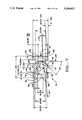
- FIG. 7shows a cross-sectional side elevation view of the ferrule 70.
- First, second and third interior wall regions 82, 84 and 86define a conduit 88 extending between the inlet opening 78 and the outlet opening 80.
- the respective first, second and third interior wall regions 82, 84 and 86each have substantially cylindrical contours and are aligned along a central axis 90 of the conduit 88.
- first, second and third interior wall regionsdefine three separate taper lock surfaces.
- Each of these three interior wall regionscan be sized and contoured to conform to the shape of a different connector portion from a different connector.
- a connectornor any portion of a connector forms any part of the present invention.
- the first interior wall region 82can be sized and contoured to conform to the shape of a portion 83 of the first connector 58 of FIG. 3.
- the second interior wall region 86for example, can be sized and contoured to conform to the shape of a portion 87 of the second connector 60 of FIG. 4.
- the interior wall regions of FIG. 7are drawn to a different scale than the connectors of FIGS. 3 and 4.
- the second interior wall region 84for example, can be sized and contoured to conform to the shape of yet another connector (not shown).
- a taper lockis caused by a frictional engagement force that results when a connector becomes lodged within the ferrule 70.
- the different sizing and contouring of the three different interior wall regions 82, 84 and 86ensures that differently sized and contoured connector portions can become lodged against different interior wall regions.
- first connector 58when the first connector 58 is inserted into the inlet opening 78 of the ferrule 70, it becomes lodged against the first interior wall region, forming a taper lock with it.
- second connector 60when the second connector 60 is inserted into the inlet opening 78 of the ferrule 70, it becomes lodged against the third interior wall region 86, forming a taper lock with it.
- the first interior wall region 82has interior walls that are inclined relative to the central axis 90 so as to define a generally conical shape in which a diameter of a first segment of the conduit 88 defined by the first interior wall region 82 decreases with increasing distance from the inlet opening 78.
- a first interior annular shoulder 92demarcates the end of the first interior wall region 82.
- a second segment of the conduit 88is defined by the second interior wall region 84 which also is substantially conical in shape. Like the first interior wall region, the interior walls of the second interior wall region 84 are inclined relative to the central axis 90 such that the diameter of a second conduit segment decreases with increasing distance from the inlet opening 78. A second interior annular shoulder 94 demarcates the end of the second interior wall region 84.
- a third segment of the conduit 88is defined by the third conical interior wall region 86.
- the interior walls of the third interior wall regionare inclined relative to the central axis 90 such that the diameter of the third conduit segment decreases with increasing distance from the inlet opening 78.
- the dimensions of the third interior wall regionare those of a luer.
- a taper lock between a connector portion such as portions 83 or 87 inserted into the inlet opening 78results because the diameter of an interior wall region, such as region 82, 84 or 86, decreases or tapers down, with increasing distance from an inlet to the region. It is the tapered inner wall region diameter of regions 82, 84 or 86 that facilitate the formation of taper locks in these wall regions.
- a taper lockcan be formed in which inner wall regions have contours formed in them such as ridges, steps or bumps.
- contours formed in themsuch as ridges, steps or bumps.
- spiral threaded ridges or steps or other structures formed in inner wall regionscan afford a better lock by permitting the twisting of a connector portion into engagement with the inner wall regions.
- tapered inner walls 302form a smooth taper about a central axis 307 within a first inner wall segment such that the inner wall diameter decreases with increasing distance from an inlet opening 306.
- inwardly extending concentric ridges 304form a spiral step about the central axis 307, such that the inner wall diameter decreases with increasing distance from the inlet opening 306.
- the tapered inner walls 302 and the spiral ridges 304are concentrically aligned with the central axis 307 which extends between the inlet opening 306 and an outlet opening 308.
- a taper lockcan be formed with the surfaces of the first or second inner wall regions.
- tapered inner walls 402form a smooth taper about a central axis 407 within a first inner wall segment such that the inner wall diameter decreases with increasing distance from an inlet opening 406.
- inwardly extending concentric ridges 404form a series of concentric steps about the central axis 407, such that the inner wall diameter decreases with increasing distance from the inlet opening 406.
- the tapered inner walls 402 and the ridges 404are concentrically aligned with a central axis 407 which extends between the inlet opening 406 and an outlet opening 408.
- a taper lockcan be formed either with surfaces of the first or second inner wall segments.
- a first inner wall segmentincludes a spiral-threaded path 504 about a central axis 507.
- a connector(not shown) having appropriately sized outwardly extending spiral threads can be screwed into place within the first inner wall segment.
- inwardly extending concentric inclined steps 505are formed about the central axis 507. For each respective step 505, the inner wall diameter decreases with each increasing distance from an inlet opening 506.
- the spiral ridges 504 and the steps 505are concentrically aligned with the central axis 507 which extends between the inlet opening 506 and an outlet opening 508.
- inner walls 603are shaped to conform to a ball connector (not shown).
- tapered inner walls 602form a smooth taper about a central axis 607 such that the inner wall diameter decreases with increasing distance from an inlet opening 606.
- inwardly extending concentric spiral ridges 604form a spiral thread sized to form a threaded interconnect with an appropriately sized connector (not shown) having complementary spiral threads.
- the first inner walls 603 inner walls 602 and the concentric ridges 604are concentrically aligned with the central axis 607 which extends between the inlet opening 606 and an outlet opening 608.
- tapered inner walls 702form a smooth taper about a central axis 707 within a first segment of the ferrule 700 such that the inner wall diameter decreases with increasing distance from an inlet opening 706.
- Outwardly extending barbs 704are formed in an exterior wall of the first segment and are used to form a gripping interconnect with an appropriately sized connector (not shown).
- the tapered inner walls 702are concentrically aligned with the central axis 707 which extends between the inlet opening 706 and an outlet opening 708.
- first tapered inner walls 802form a smooth taper about a central axis 807 within a first inner wall segment such that the inner wall diameter decreases with increasing distance from an inlet opening 806.
- inwardly extending concentric spiral ridges 804form a spiral thread about the central axis 807, such that an appropriately sized connector having complementary spiral threads (not shown) can be secured in place.
- Second tapered inner walls 805form a second smooth taper about the central axis 807 within a third inner wall segment such that the inner wall diameter decreases with increasing distance from the inlet opening 806.
- the first and second tapered inner walls 802 and 805 and the spiral ridges 804are concentrically aligned with the central axis 807 which extends between the inlet opening 806 and an outlet opening 808.
- FIG. 20Aan alternative embodiment of a ferrule 900 used to form an offset lock is shown.
- inner walls 902are formed about a first axis 903 within a first inner wall segment.
- second inner walls 905are formed about a second axis 906.
- the first and second tapered inner walls 902, 905define a path between inlet opening 904 and an outlet opening 907.
- FIG. 20Bthere is shown a connector 908, which forms no part of the present invention, which can be interconnected with the offset lock ferrule 900 of FIG. 20A.
- a ferrule in accordance with the present inventioncan be constructed with any of a variety of gripping mechanisms for gripping different external connectors (which form no part of the present invention).
- gripping mechanismssuch as smooth tapers, spiral and nonspiral steps, threads, barbs, ball and socket and offset locks have been specifically described, alternative gripping mechanisms and different combinations of gripping mechanisms can be employed without departing from the invention.
- the outer edges of the middle and bottom outwardly extending annular ribs 74, 76are inclined relative to the central axis 90 such that the diameter of each of these respective annular ribs 74, 76 decreases with increasing distance from the inlet opening 78. Moreover, the respective shoulders 96, 98 and 100 of the top, middle and bottom annular rings are rounded. The inclined and rounded edges of the outwardly protruding annular ribs can facilitate the process of inserting the ferrule 70 into an inlet end portion of a feeding tube as explained more fully below.
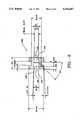
- FIG. 8there is shown a cross-sectional elevation view of an inlet end portion 102 of an enteral tube, in accordance with the presently preferred embodiment of the invention, which incorporates the ferrule 70.
- An enteral feeding tubefeeds into the digestive tract.
- the feeding tubeis formed from an elastomeric silicone material and can be formed by injection molding.
- the inlet end portion 102defines an inlet port opening 104 and defines a first passage 106 between the inlet port opening 104 and the inlet opening 78 of the ferrule 70.
- the outlet opening 80 of the ferrule 70communicates with a second elongated passage 108 defined by an elongated tube portion 110 of the feeding tube, only a short segment of which is shown.
- An arm 112is integrally formed with the end portion 102 and has a plug 114 extending therefrom.
- the arm 112can be bent, and the plug 114 can be inserted into the inlet port opening 104, whereupon it becomes lodged in a space 116 between two inwardly projecting annular protrusions 118, 120 integrally formed in the inlet end portion 102. In this manner, the opening 104 can be closed when the end portion 102 is not in use.
- the inlet end portion 102when the inlet end portion 102 is in use and a connector, such as the first or the second connector 58 or 60, is inserted through the inlet port opening 104 and has formed a taper lock with one of the inner wall regions of the ferrule 70, the inwardly projecting annular protrusions 118, 120 abut against the connector.
- the protrusions 118, 120advantageously produce a fluid seal with a connector inserted through the inlet port opening 104 to prevent fluid leakage from the opening 104.
- annular protrusionsalternatively could be invalid within an annular inset (not shown) in the ferrule 70 or could be positioned downstream from the ferrule 70 adjacent to the ferrule outlet port 80.
- the outwardly projecting annular ribs 74, 76, 78 of the ferrule 70grip inwardly projecting annular ribs 122, 124 which are integrally formed in the end portion and which are contoured to fit snugly between the ribs 74, 76, 78. In this manner, the ribs 74, 76, 78 hold the ferrule 70 in place within the inlet end portion 102. It will be appreciated that although annular ribs 74, 76, 78 are used to grip the end portion 102, differently shaped objects could be used to accomplish that purpose. For example, the outer surface of the ferrule 70 could be abraded so as to roughen it to allow it to grip the interior of the end portion 102.
- the outer surface of the ferrule 70could have protrusions in the shape of individual upstanding barbs or in the shape of helical ridges.
- Annular ribs 74, 76 of ferrule 70afford such removability as do similar annular ribs of ferrule 126 and of the alternative ferrules of FIGS. 14-19. Removability can be important, for example, in situations where one type of ferrule is to be removed and another type is to be inserted in order to accommodate a variety of different connectors.
- a connector(which forms no part of the present invention) may be suited to connection to a barbed gripping mechanism such as the barbs 704 of ferrule 700 of FIG. 18. Consequently, it will be desirable to install such a barbed ferrule. If necessary, a previously installed ferrule will have to be removed.
- FIG. 9there is shown an alternative embodiment of a ferrule 126 in accordance with the invention.
- the alternative ferrule 126is generally similar to the presently preferred ferrule 70 except that it includes only two interior wall regions 128, 130 for use as taper lock surfaces instead of the three such regions 82, 84, 86 of the ferrule 70.
- the ferrule 126includes a conduit having a central axis 132. The conduit extends between an inlet opening 134 and an outlet opening 136.
- FIG. 10shows a cross-sectional elevation view of an enteral tube 138 which incorporates the alternative ferrule 126.
- the enteral tube 138includes an inlet end portion 140 defining an inlet port opening 142. It also includes an elongated tube member 144, an inflatable balloon 146 and a locking ring 148.
- the enteral tube 138also includes a valve 148 for use in providing fluid to the balloon 146 and another end portion 150 defining another port opening 152 that can be used to provide medication.
- the ferrulecan be mounted on a pin, for example, and a silicone end portion can be injection molded about it.
- the silicone end portioncan be produced first, and later the ferrule can be mounted on a mandril and be forced into position within the end portion.
- the inclined and rounded outer portions of the outwardly extending annular ribsare useful to ensure that the ferrule does not become snagged as it is forced into the end portion.
- FIGS. 7 and 9include interior wall regions 82, 84, 86 and 128,130 for use in forming taper locks with differently sized connector portions
- alternative locking mechanismscan be employed without departing from the invention.
- a thread connection, barbs, a ball joint or a quick spike jointcould be employed.
- the interior wall regionsneed not be smooth or gradually decreasing in diameter to be employed in forming a taper lock with a connector.
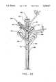
- the first branched ferrule 160is disposed within an elongated tube member 162 which defines a jejunal tube 164, a gastrostomy tube 166 and a fluid line 168.
- the elongated tube member 162is formed from a flexible elastomeric material such as silicone.
- the first branched ferrule 160defines first and second jejunal inlet openings 170, 172 that provide fluid access, through a first tubule 174, to the jejunal tube 164.
- First and second gastrostomy inlet openings 176, 178provide fluid access, through a second tubule 180, to the gastrostomy tube 166.
- the first jejunal and gastrostomy inlet openings 170, 176for example can be used to receive food, and the second jejunal and gastrostomy inlet openings 172, 178, for example, can be used to receive medicine.
- the elongated tube member 162defines a fluid port 188 in which a valve (not shown) can be installed to control the flow of a fluid through the fluid line 168.
- a region accessible through the first jejunal inlet opening 170includes first and second conical inner wall regions 182,184 that can be used to form taper locks with a connector portion (not shown). That same region accessible through the first jejunal inlet opening 170 also defines threads 186 that can be threaded to a complementary threaded connector (not shown).
- the first branched ferrule 160can form a taper lock or a threaded engagement with different connectors inserted into the first jejunal inlet opening 170.
- the second branched ferrule 190is disposed within an elongated tube member 192 which defines a single enteral tube 194 and a fluid line 196.
- the second branched ferrule 190defines first, second, third and fourth inlet openings 198, 200, 202, 204, each of which provides fluid access to a single tubule 206 that communicates with the single enteral tube 194.
- the elongated tube member 192defines a fluid port 208 in which a valve (not shown) can be installed to control the flow of fluid through the fluid line 196.
- Two conical barbs 210upstand from the second branched ferrule 190 about the second inlet port external to the elongated tube member 192.
- the barbs 210can be used to engage and hold in place a connector (not shown) formed from a flexible material such as silicone.
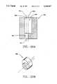
- FIG. 13there is shown a cross-sectional view of another ferrule 212 in accordance with the invention.
- the ferrule 212defines a conduit extending between an inlet opening 214 and an outlet opening 216. It also defines first and second conical inner wall regions 218, 220, aligned about a central axis 221, that can be used to form respective taper locks with differently sized and contoured connector portions.
- a barbed stem 222extends longitudinally along the axis and defines the outlet opening 216. The barbs can be used to secure the ferrule to an enteral tube inlet opening (not shown) so as to adapt such a tube opening to withstand repeated insertions and removals of differently sized connectors without suffering, stretching or wear-and-tear.
- the ferrules 70, 126 in accordance with the present embodiments of the inventionadvantageously can be used to ensure that connectors such as the first and second connectors 58, 60 can be inserted and removed from an end portion of a feeding tube, without the exertion of undue force and without resulting in unwanted stretching of the end portion.
- the inner wall regions of the ferrules 70, 126can be sized and contoured to precisely conform to the shape of a number of different connector portions.
- the branched ferrules of FIGS. 11 and 12include gripping mechanisms in the form of threads 186, taper locks and conical barbs 210, it will be appreciated that alternative gripping mechanisms7 can be employed. For example, gripping mechanisms like those disclosed in FIGS.
- FIGS. 11 and 12multiple types of gripping mechanisms can be employed at each inlet port of a multiple port branched ferrule.
- a ferrulecan be produced which employs more than one type of gripping mechanism.
- the ferrule 212includes first and second inner wall regions 218, 220 that can form taper locks and a barbed stem 222
- other types and combinations of gripping mechanismssuch as steps, threads, offset locks and ball and sockets can be employed without departing from the invention.
- additional inner wall segments or exterior wall segmentscan be employed which include still further gripping mechanisms.
- even more than three gripping mechanismsmay be used per ferrule.
- inlet branchesare shown for each of the two ferrules of FIGS. 11 and 12, it will be understood that additional inlet branches could be added without departing from the invention.
Landscapes
- Health & Medical Sciences (AREA)
- Life Sciences & Earth Sciences (AREA)
- Animal Behavior & Ethology (AREA)
- General Health & Medical Sciences (AREA)
- Public Health (AREA)
- Veterinary Medicine (AREA)
- Heart & Thoracic Surgery (AREA)
- Pulmonology (AREA)
- Engineering & Computer Science (AREA)
- Anesthesiology (AREA)
- Biomedical Technology (AREA)
- Hematology (AREA)
- Infusion, Injection, And Reservoir Apparatuses (AREA)
Abstract
Description
Claims (10)
Priority Applications (2)
| Application Number | Priority Date | Filing Date | Title |
|---|---|---|---|
| US07/632,776US5234417A (en) | 1989-12-21 | 1990-12-21 | Enternal tube incorporating a ferrule |
| US08/010,908US5250040A (en) | 1989-12-21 | 1993-01-28 | Ferrule and enteral tube incorporating a ferrule |
Applications Claiming Priority (2)
| Application Number | Priority Date | Filing Date | Title |
|---|---|---|---|
| US45330889A | 1989-12-21 | 1989-12-21 | |
| US07/632,776US5234417A (en) | 1989-12-21 | 1990-12-21 | Enternal tube incorporating a ferrule |
Related Parent Applications (1)
| Application Number | Title | Priority Date | Filing Date |
|---|---|---|---|
| US45330889AContinuation-In-Part | 1989-12-21 | 1989-12-21 |
Related Child Applications (1)
| Application Number | Title | Priority Date | Filing Date |
|---|---|---|---|
| US08/010,908DivisionUS5250040A (en) | 1989-12-21 | 1993-01-28 | Ferrule and enteral tube incorporating a ferrule |
Publications (1)
| Publication Number | Publication Date |
|---|---|
| US5234417Atrue US5234417A (en) | 1993-08-10 |
Family
ID=27037066
Family Applications (1)
| Application Number | Title | Priority Date | Filing Date |
|---|---|---|---|
| US07/632,776Expired - LifetimeUS5234417A (en) | 1989-12-21 | 1990-12-21 | Enternal tube incorporating a ferrule |
Country Status (1)
| Country | Link |
|---|---|
| US (1) | US5234417A (en) |
Cited By (48)
| Publication number | Priority date | Publication date | Assignee | Title |
|---|---|---|---|---|
| US5527280A (en)* | 1995-03-29 | 1996-06-18 | The Children's Seashore House | Multi-lumen enteral feeding and medicating device |
| US5556385A (en)* | 1994-12-06 | 1996-09-17 | Corpak, Inc. | Improved percutaneous access device |
| US5738661A (en)* | 1995-06-16 | 1998-04-14 | Larice; Gennaro | Medical device for holding a feeding tube and use thereof |
| US5951497A (en)* | 1996-09-03 | 1999-09-14 | Clinical Innovation Associates, Inc. | Pressure catheter device with enhanced positioning features |
| USD418220S (en)* | 1998-03-26 | 1999-12-28 | Applied Medical Technology, Inc. | Low profile balloon feeding device |
| US20020077604A1 (en)* | 2000-12-19 | 2002-06-20 | Kimberly-Clark Worldwide, Inc. | Sealing valve assembly for medical products |
| US20030199829A1 (en)* | 2002-04-19 | 2003-10-23 | Keun-Ho Lee | Catheter |
| US20030225369A1 (en)* | 2002-05-31 | 2003-12-04 | Kimberly-Clark Worldwide, Inc. | Low profile transpyloric jejunostomy system |
| US20030225393A1 (en)* | 2002-05-31 | 2003-12-04 | Kimberly-Clark Worldwide, Inc. | Low profile transpyloric jejunostomy system and method to enable |
| US20030225392A1 (en)* | 2002-05-31 | 2003-12-04 | Kimberly-Clark Worldwide, Inc. | Low profile transpyloric jejunostomy system and method to enable |
| US6767340B2 (en) | 2000-12-19 | 2004-07-27 | Kimberly-Clark Worldwide, Inc. | Sealing valve assembly for medical products |
| US6808521B1 (en) | 1999-11-18 | 2004-10-26 | Kimberly-Clark Worldwide, Inc. | Enteral feeding adapter |
| USD500133S1 (en) | 2003-08-06 | 2004-12-21 | Kimberly-Clarke Worldwide, Inc. | Bolster |
| USD500132S1 (en) | 2003-08-06 | 2004-12-21 | Kimberly-Clark Worldwide, Inc. | Bolster |
| USD500552S1 (en) | 2003-08-06 | 2005-01-04 | Kimberly-Clark Worldwide, Inc. | Bolster |
| USD500853S1 (en) | 2003-08-06 | 2005-01-11 | Kimberly-Clarke Worldwide, Inc. | Bolster |
| US20050033269A1 (en)* | 2003-08-06 | 2005-02-10 | Kimberly-Clark Worldwide, Inc. | Ferrule and enteral tube incorporating a ferrule |
| US20050033268A1 (en)* | 2003-08-06 | 2005-02-10 | Kimberly-Clark Worldwide, Inc. | Connector with protrusion adapted for interconnection with second member |
| US20050187524A1 (en)* | 2000-12-19 | 2005-08-25 | Willis Allan F. | Sealing valve assembly for medical products |
| US20050245899A1 (en)* | 2003-10-28 | 2005-11-03 | Swisher David R | Dual purpose adapter |
| US20060004345A1 (en)* | 2004-06-30 | 2006-01-05 | Mcmichael Donald J | Retention device for medical components |
| US20060095019A1 (en)* | 2004-11-02 | 2006-05-04 | Dikeman W C | Urinary catheter |
| US20060122559A1 (en)* | 2002-10-28 | 2006-06-08 | Benedict Shia | Automatic valve |
| US20060129092A1 (en)* | 2002-10-28 | 2006-06-15 | Sherwood Services Ag | Single lumen adapter for automatic valve |
| US7066914B2 (en) | 2000-07-12 | 2006-06-27 | Bird Products Corporation | Catheter having a tip with an elongated collar |
| US20060264935A1 (en)* | 2005-05-04 | 2006-11-23 | White Patrick M | Orthopedic stabilization device |
| US20070282168A1 (en)* | 2006-04-10 | 2007-12-06 | Kaye Christopher J | Biopsy inlet valve |
| USD561329S1 (en) | 2006-10-04 | 2008-02-05 | Kimberly-Clark Worldwide, Inc. | Low profile transpyloric jejunostomy catheter |
| USD569507S1 (en)* | 2007-04-09 | 2008-05-20 | C.R. Bard, Inc. | Luer hub connector |
| US7628775B2 (en) | 2004-09-24 | 2009-12-08 | Boston Scientific Scimed, Inc. | Safety Y-port adaptor and medical catheter assembly including the same |
| US20100113880A1 (en)* | 2008-11-05 | 2010-05-06 | Page Charles W | Gastrostomy-jejunostomy tube apparatus and method for endoscopically placing same within a patient |
| WO2010045055A3 (en)* | 2008-10-13 | 2010-07-01 | Ethicon, Inc. | Fluid connector for endoscope reprocessing system |
| US20100331787A1 (en)* | 2009-06-30 | 2010-12-30 | Tyco Healthcare Group Lp | Female adaptor for feeding line |
| US7976518B2 (en) | 2005-01-13 | 2011-07-12 | Corpak Medsystems, Inc. | Tubing assembly and signal generator placement control device and method for use with catheter guidance systems |
| US20120029481A1 (en)* | 2009-04-07 | 2012-02-02 | V. KRÜTTEN MEDIZINISCHE EINMALGERÄTE GmbH | Connection piece for the tube of an enteral feeding tube and assembly of an enteral feeding tube and an enteral transfer system |
| US8702596B2 (en) | 2010-09-17 | 2014-04-22 | United States Endoscopy Group, Inc. | Biopsy inlet valve improvements |
| US20140114259A1 (en)* | 2012-10-24 | 2014-04-24 | Katrina Durham | Feeding tube extension |
| US20140163528A1 (en)* | 2011-07-27 | 2014-06-12 | The University Of Kansas | Maneuverable nasoenteric feeding tube |
| EP2829297A1 (en)* | 2013-07-23 | 2015-01-28 | Becton Dickinson France | Adaptor for a needleless access device and method for connecting said device thereon |
| US9028441B2 (en) | 2011-09-08 | 2015-05-12 | Corpak Medsystems, Inc. | Apparatus and method used with guidance system for feeding and suctioning |
| WO2015111680A1 (en)* | 2014-01-27 | 2015-07-30 | テルモ株式会社 | Catheter and catheter hub |
| US20160051135A1 (en)* | 2012-09-13 | 2016-02-25 | Emmy Medical, Llc. | 4-way cystoscopy catheter |
| US20160143815A1 (en)* | 2014-11-25 | 2016-05-26 | Corpak Medsystems, Inc. | Dual material y-connector |
| US9433771B2 (en) | 2008-10-13 | 2016-09-06 | Ethicon, Inc. | Quick disconnect fluid connector |
| US9565995B2 (en) | 2008-10-13 | 2017-02-14 | Ethicon, Inc. | Endoscope channel separator |
| USD908865S1 (en) | 2018-08-17 | 2021-01-26 | Emmy Medical, Llc | Catheter |
| WO2024119043A1 (en)* | 2022-12-01 | 2024-06-06 | Boston Scientific Scimed, Inc. | Multi-endoscope platform coupling |
| US12208064B2 (en) | 2020-04-30 | 2025-01-28 | Avent, Inc. | Polyurethane bonding skeleton for feeding tube device |
Citations (17)
| Publication number | Priority date | Publication date | Assignee | Title |
|---|---|---|---|---|
| US1242174A (en)* | 1917-02-07 | 1917-10-09 | James C Gooch | Device for applying liquids. |
| US1865926A (en)* | 1930-11-05 | 1932-07-05 | Arthur J Laing | Junction box |
| US2957196A (en)* | 1958-11-25 | 1960-10-25 | Shur Lok Corp | Bolt and stud spacer for lightweight sandwich panels |
| US2961691A (en)* | 1958-02-27 | 1960-11-29 | United States Steel Corp | Grommet for guiding wire and the like |
| GB1380991A (en)* | 1972-02-01 | 1975-01-22 | Searle & Co | Catheters |
| US4232421A (en)* | 1979-03-16 | 1980-11-11 | Orion Industries, Inc. | Alternative diameter gasket |
| US4257416A (en)* | 1979-05-03 | 1981-03-24 | David Prager | Multi-channel venipuncture infusion set |
| US4349024A (en)* | 1981-04-01 | 1982-09-14 | Ralston Jr Philip G | Multiple adapter device for interconnecting tubing of different sizes |
| US4685901A (en)* | 1984-11-05 | 1987-08-11 | Medical Innovations Corporation | Gastro-jejunal feeding device |
| US4701162A (en)* | 1985-09-24 | 1987-10-20 | The Kendall Company | Foley catheter assembly |
| US4774940A (en)* | 1983-06-15 | 1988-10-04 | Linder Gerald S | Breathing circuit connector for use in anesthesiology |
| US4963132A (en)* | 1988-11-11 | 1990-10-16 | Gibson Roger M | Capped fluidic connector |
| US4969879A (en)* | 1988-07-26 | 1990-11-13 | Gish Biomedical, Inc. | Body fluid interconnect |
| US4994048A (en)* | 1988-09-19 | 1991-02-19 | Becton, Dickinson And Company | Apparatus and method for connecting a passageway and openings with a connector |
| US5047021A (en)* | 1989-08-29 | 1991-09-10 | Utterberg David S | Male luer lock medical fitting |
| US5049139A (en)* | 1987-08-29 | 1991-09-17 | Giltech Limited | Apparatus for antimicrobial use |
| US5057093A (en)* | 1989-09-07 | 1991-10-15 | Abbott Laboratories | Medical device improvements for enteral feeding |
- 1990
- 1990-12-21USUS07/632,776patent/US5234417A/ennot_activeExpired - Lifetime
Patent Citations (17)
| Publication number | Priority date | Publication date | Assignee | Title |
|---|---|---|---|---|
| US1242174A (en)* | 1917-02-07 | 1917-10-09 | James C Gooch | Device for applying liquids. |
| US1865926A (en)* | 1930-11-05 | 1932-07-05 | Arthur J Laing | Junction box |
| US2961691A (en)* | 1958-02-27 | 1960-11-29 | United States Steel Corp | Grommet for guiding wire and the like |
| US2957196A (en)* | 1958-11-25 | 1960-10-25 | Shur Lok Corp | Bolt and stud spacer for lightweight sandwich panels |
| GB1380991A (en)* | 1972-02-01 | 1975-01-22 | Searle & Co | Catheters |
| US4232421A (en)* | 1979-03-16 | 1980-11-11 | Orion Industries, Inc. | Alternative diameter gasket |
| US4257416A (en)* | 1979-05-03 | 1981-03-24 | David Prager | Multi-channel venipuncture infusion set |
| US4349024A (en)* | 1981-04-01 | 1982-09-14 | Ralston Jr Philip G | Multiple adapter device for interconnecting tubing of different sizes |
| US4774940A (en)* | 1983-06-15 | 1988-10-04 | Linder Gerald S | Breathing circuit connector for use in anesthesiology |
| US4685901A (en)* | 1984-11-05 | 1987-08-11 | Medical Innovations Corporation | Gastro-jejunal feeding device |
| US4701162A (en)* | 1985-09-24 | 1987-10-20 | The Kendall Company | Foley catheter assembly |
| US5049139A (en)* | 1987-08-29 | 1991-09-17 | Giltech Limited | Apparatus for antimicrobial use |
| US4969879A (en)* | 1988-07-26 | 1990-11-13 | Gish Biomedical, Inc. | Body fluid interconnect |
| US4994048A (en)* | 1988-09-19 | 1991-02-19 | Becton, Dickinson And Company | Apparatus and method for connecting a passageway and openings with a connector |
| US4963132A (en)* | 1988-11-11 | 1990-10-16 | Gibson Roger M | Capped fluidic connector |
| US5047021A (en)* | 1989-08-29 | 1991-09-10 | Utterberg David S | Male luer lock medical fitting |
| US5057093A (en)* | 1989-09-07 | 1991-10-15 | Abbott Laboratories | Medical device improvements for enteral feeding |
Cited By (81)
| Publication number | Priority date | Publication date | Assignee | Title |
|---|---|---|---|---|
| US5556385A (en)* | 1994-12-06 | 1996-09-17 | Corpak, Inc. | Improved percutaneous access device |
| US5527280A (en)* | 1995-03-29 | 1996-06-18 | The Children's Seashore House | Multi-lumen enteral feeding and medicating device |
| US5738661A (en)* | 1995-06-16 | 1998-04-14 | Larice; Gennaro | Medical device for holding a feeding tube and use thereof |
| US5951497A (en)* | 1996-09-03 | 1999-09-14 | Clinical Innovation Associates, Inc. | Pressure catheter device with enhanced positioning features |
| US6231524B1 (en) | 1996-09-03 | 2001-05-15 | Clinical Innovation Associates, Inc. | Pressure catheter device with enhanced fluid monitoring features |
| USD418220S (en)* | 1998-03-26 | 1999-12-28 | Applied Medical Technology, Inc. | Low profile balloon feeding device |
| US6808521B1 (en) | 1999-11-18 | 2004-10-26 | Kimberly-Clark Worldwide, Inc. | Enteral feeding adapter |
| US7066914B2 (en) | 2000-07-12 | 2006-06-27 | Bird Products Corporation | Catheter having a tip with an elongated collar |
| US20020077604A1 (en)* | 2000-12-19 | 2002-06-20 | Kimberly-Clark Worldwide, Inc. | Sealing valve assembly for medical products |
| US8579870B2 (en) | 2000-12-19 | 2013-11-12 | Kimberly-Clark Worldwide, Inc. | Sealing valve assembly for medical products |
| US20070255257A1 (en)* | 2000-12-19 | 2007-11-01 | Kimberly-Clark Worldwide | Sealing Valve Assembly for Medical Products |
| US6767340B2 (en) | 2000-12-19 | 2004-07-27 | Kimberly-Clark Worldwide, Inc. | Sealing valve assembly for medical products |
| US6908449B2 (en) | 2000-12-19 | 2005-06-21 | Kimberly-Clark Worldwide, Inc. | Sealing valve assembly for medical products |
| US20050187524A1 (en)* | 2000-12-19 | 2005-08-25 | Willis Allan F. | Sealing valve assembly for medical products |
| US6955663B2 (en)* | 2002-04-19 | 2005-10-18 | Keun-Ho Lee | Catheter for extracting and inserting humors |
| US20030199829A1 (en)* | 2002-04-19 | 2003-10-23 | Keun-Ho Lee | Catheter |
| US20030225392A1 (en)* | 2002-05-31 | 2003-12-04 | Kimberly-Clark Worldwide, Inc. | Low profile transpyloric jejunostomy system and method to enable |
| US20030225369A1 (en)* | 2002-05-31 | 2003-12-04 | Kimberly-Clark Worldwide, Inc. | Low profile transpyloric jejunostomy system |
| US20030225393A1 (en)* | 2002-05-31 | 2003-12-04 | Kimberly-Clark Worldwide, Inc. | Low profile transpyloric jejunostomy system and method to enable |
| US7713246B2 (en) | 2002-10-28 | 2010-05-11 | Covidien Ag | Automatic valve |
| US20060122559A1 (en)* | 2002-10-28 | 2006-06-08 | Benedict Shia | Automatic valve |
| US20060129092A1 (en)* | 2002-10-28 | 2006-06-15 | Sherwood Services Ag | Single lumen adapter for automatic valve |
| USD500133S1 (en) | 2003-08-06 | 2004-12-21 | Kimberly-Clarke Worldwide, Inc. | Bolster |
| USD500132S1 (en) | 2003-08-06 | 2004-12-21 | Kimberly-Clark Worldwide, Inc. | Bolster |
| US20050033268A1 (en)* | 2003-08-06 | 2005-02-10 | Kimberly-Clark Worldwide, Inc. | Connector with protrusion adapted for interconnection with second member |
| US20050033269A1 (en)* | 2003-08-06 | 2005-02-10 | Kimberly-Clark Worldwide, Inc. | Ferrule and enteral tube incorporating a ferrule |
| USD500552S1 (en) | 2003-08-06 | 2005-01-04 | Kimberly-Clark Worldwide, Inc. | Bolster |
| USD500853S1 (en) | 2003-08-06 | 2005-01-11 | Kimberly-Clarke Worldwide, Inc. | Bolster |
| US20050245899A1 (en)* | 2003-10-28 | 2005-11-03 | Swisher David R | Dual purpose adapter |
| US20080179882A1 (en)* | 2003-10-28 | 2008-07-31 | Hanlon James G | Fluid Adapter for Valve |
| US20060004345A1 (en)* | 2004-06-30 | 2006-01-05 | Mcmichael Donald J | Retention device for medical components |
| US7666178B2 (en) | 2004-06-30 | 2010-02-23 | Kimberly-Clark Worldwide, Inc. | Retention device for medical components |
| US7628775B2 (en) | 2004-09-24 | 2009-12-08 | Boston Scientific Scimed, Inc. | Safety Y-port adaptor and medical catheter assembly including the same |
| US20060095019A1 (en)* | 2004-11-02 | 2006-05-04 | Dikeman W C | Urinary catheter |
| US9889277B2 (en) | 2005-01-13 | 2018-02-13 | Avent, Inc. | Tubing assembly and signal generator placement control device and method for use with catheter guidance systems |
| US10549074B2 (en) | 2005-01-13 | 2020-02-04 | Avent, Inc. | Tubing assembly and signal generation placement device and method for use with catheter guidance systems |
| US9579488B2 (en) | 2005-01-13 | 2017-02-28 | Corpak Medsystems, Inc. | Tubing assembly and signal generator placement control device and method for use with catheter guidance systems |
| US7976518B2 (en) | 2005-01-13 | 2011-07-12 | Corpak Medsystems, Inc. | Tubing assembly and signal generator placement control device and method for use with catheter guidance systems |
| US9131956B2 (en) | 2005-01-13 | 2015-09-15 | Corpak Medsystems, Inc. | Tubing assembly and signal generator placement control device and method for use with catheter guidance systems |
| US20060264935A1 (en)* | 2005-05-04 | 2006-11-23 | White Patrick M | Orthopedic stabilization device |
| US20070282168A1 (en)* | 2006-04-10 | 2007-12-06 | Kaye Christopher J | Biopsy inlet valve |
| US7967744B2 (en)* | 2006-04-10 | 2011-06-28 | U.S. Endoscopy Group, Inc. | Biopsy inlet valve |
| USD561329S1 (en) | 2006-10-04 | 2008-02-05 | Kimberly-Clark Worldwide, Inc. | Low profile transpyloric jejunostomy catheter |
| USD569507S1 (en)* | 2007-04-09 | 2008-05-20 | C.R. Bard, Inc. | Luer hub connector |
| US9565995B2 (en) | 2008-10-13 | 2017-02-14 | Ethicon, Inc. | Endoscope channel separator |
| WO2010045055A3 (en)* | 2008-10-13 | 2010-07-01 | Ethicon, Inc. | Fluid connector for endoscope reprocessing system |
| US10582984B2 (en) | 2008-10-13 | 2020-03-10 | Asp Global Manufacturing Gmbh | Endoscope channel separator |
| US10561307B2 (en) | 2008-10-13 | 2020-02-18 | Asp Global Manufacturing Gmbh | Fluid connector for endoscope reprocessing system |
| US9592373B2 (en) | 2008-10-13 | 2017-03-14 | Ethicon, Inc. | Fluid connector for endoscope reprocessing system |
| CN102186530B (en)* | 2008-10-13 | 2014-12-17 | 伊西康公司 | Fluid connector for endoscope reprocessing system |
| US9433771B2 (en) | 2008-10-13 | 2016-09-06 | Ethicon, Inc. | Quick disconnect fluid connector |
| CN102186530A (en)* | 2008-10-13 | 2011-09-14 | 伊西康公司 | Fluid connector for endoscope reprocessing system |
| US20100113880A1 (en)* | 2008-11-05 | 2010-05-06 | Page Charles W | Gastrostomy-jejunostomy tube apparatus and method for endoscopically placing same within a patient |
| US20120029481A1 (en)* | 2009-04-07 | 2012-02-02 | V. KRÜTTEN MEDIZINISCHE EINMALGERÄTE GmbH | Connection piece for the tube of an enteral feeding tube and assembly of an enteral feeding tube and an enteral transfer system |
| US7955317B2 (en) | 2009-06-30 | 2011-06-07 | Tyco Healthcare Group Lp | Female adaptor for feeding line |
| US20100331787A1 (en)* | 2009-06-30 | 2010-12-30 | Tyco Healthcare Group Lp | Female adaptor for feeding line |
| US8702596B2 (en) | 2010-09-17 | 2014-04-22 | United States Endoscopy Group, Inc. | Biopsy inlet valve improvements |
| US9526674B2 (en)* | 2011-07-27 | 2016-12-27 | The University Of Kansas | Maneuverable nasoenteric feeding tube |
| US20140163528A1 (en)* | 2011-07-27 | 2014-06-12 | The University Of Kansas | Maneuverable nasoenteric feeding tube |
| US9918907B2 (en) | 2011-09-08 | 2018-03-20 | Avent, Inc. | Method for electromagnetic guidance of feeding and suctioning tube assembly |
| US9028441B2 (en) | 2011-09-08 | 2015-05-12 | Corpak Medsystems, Inc. | Apparatus and method used with guidance system for feeding and suctioning |
| US20160051135A1 (en)* | 2012-09-13 | 2016-02-25 | Emmy Medical, Llc. | 4-way cystoscopy catheter |
| US10376137B2 (en)* | 2012-09-13 | 2019-08-13 | Emmy Medical, Llc | Indwelling bladder catheter |
| US20140114259A1 (en)* | 2012-10-24 | 2014-04-24 | Katrina Durham | Feeding tube extension |
| EP3505208A1 (en)* | 2013-07-23 | 2019-07-03 | Becton Dickinson France | Needleless access device |
| US10933228B2 (en) | 2013-07-23 | 2021-03-02 | Becton Dickinson France | Adaptor for a needleless access device and method for connecting said device thereon |
| US12109386B2 (en) | 2013-07-23 | 2024-10-08 | Becton Dickinson France | Adaptor for a needleless access device and method for connecting said device thereon |
| EP2829297A1 (en)* | 2013-07-23 | 2015-01-28 | Becton Dickinson France | Adaptor for a needleless access device and method for connecting said device thereon |
| EP3919103A1 (en)* | 2013-07-23 | 2021-12-08 | Becton Dickinson France | Adaptator for a needleless access device |
| CN113476736A (en)* | 2013-07-23 | 2021-10-08 | 贝克顿迪金森法国公司 | Adapter for needleless interface device and method of connecting said device thereto |
| WO2015011151A1 (en)* | 2013-07-23 | 2015-01-29 | Becton Dickinson France | Adaptor for a needleless access device and method for connecting said device thereon |
| WO2015111680A1 (en)* | 2014-01-27 | 2015-07-30 | テルモ株式会社 | Catheter and catheter hub |
| US20160143815A1 (en)* | 2014-11-25 | 2016-05-26 | Corpak Medsystems, Inc. | Dual material y-connector |
| CN106999703B (en)* | 2014-11-25 | 2020-08-18 | 科帕克麦迪系统有限公司 | Double-material Y-shaped connector |
| US10071234B2 (en)* | 2014-11-25 | 2018-09-11 | Avent, Inc. | Dual material Y-connector |
| AU2015353789B2 (en)* | 2014-11-25 | 2019-11-28 | Avent, Inc. | Dual material Y-connector |
| CN106999703A (en)* | 2014-11-25 | 2017-08-01 | 科帕克麦迪系统有限公司 | Bi-material layers Y-connection |
| USD908865S1 (en) | 2018-08-17 | 2021-01-26 | Emmy Medical, Llc | Catheter |
| USD935013S1 (en) | 2018-08-17 | 2021-11-02 | Emmy Medical, Llc | Catheter |
| US12208064B2 (en) | 2020-04-30 | 2025-01-28 | Avent, Inc. | Polyurethane bonding skeleton for feeding tube device |
| WO2024119043A1 (en)* | 2022-12-01 | 2024-06-06 | Boston Scientific Scimed, Inc. | Multi-endoscope platform coupling |
Similar Documents
| Publication | Publication Date | Title |
|---|---|---|
| US5234417A (en) | Enternal tube incorporating a ferrule | |
| US5250040A (en) | Ferrule and enteral tube incorporating a ferrule | |
| US5399173A (en) | Ferrule and enternal tube incorporating a ferrule | |
| US20050033269A1 (en) | Ferrule and enteral tube incorporating a ferrule | |
| US20050033268A1 (en) | Connector with protrusion adapted for interconnection with second member | |
| US5549657A (en) | Low profile adaptor for gastrostomy feeding tube | |
| US5702374A (en) | Male luer connector assembly | |
| US7641648B2 (en) | Low profile adaptor for use with a medical catheter | |
| US6045536A (en) | Securing device for a low profile gastrostomy tube | |
| US20050033267A1 (en) | Connector with connection mechanism adapted for releasable interconnection with tube | |
| US7666178B2 (en) | Retention device for medical components | |
| EP0702573B1 (en) | Low profile gastrostomy device with dome | |
| US6165168A (en) | Closed system adapter for catheters | |
| US6666853B2 (en) | Low profile adaptor for use with a medical catheter | |
| US20080140055A1 (en) | Lockable enteral feeding adapter | |
| JPH03106371A (en) | Medical device for injection of digestive tract | |
| EP0701454A1 (en) | Gastrostomy device with one-way cross-slit valve | |
| AU2002364299A1 (en) | Low profile adaptor for use with a medical catheter | |
| JPH04272772A (en) | Catheter having freely adjustable exter- nally fixed pillow | |
| US5242429A (en) | Enteral feeding tube with guide wire | |
| US12161604B2 (en) | Quick release connection for patient tube assembly | |
| US8939939B2 (en) | Fistula catheter | |
| JP2023523951A (en) | Polyurethane connective scaffold for feeding tube device |
Legal Events
| Date | Code | Title | Description |
|---|---|---|---|
| AS | Assignment | Owner name:MEDICAL INNOVATIONS CORPORATION, 1595 MCCANDLESS D Free format text:ASSIGNMENT OF ASSIGNORS INTEREST.;ASSIGNORS:PARKS, STEPHEN K.;FISHMAN, UDI;DECARIA, CHRISTINE;AND OTHERS;REEL/FRAME:005676/0924;SIGNING DATES FROM 19910218 TO 19910228 | |
| STCF | Information on status: patent grant | Free format text:PATENTED CASE | |
| FEPP | Fee payment procedure | Free format text:PAYOR NUMBER ASSIGNED (ORIGINAL EVENT CODE: ASPN); ENTITY STATUS OF PATENT OWNER: LARGE ENTITY Free format text:PAT HLDR NO LONGER CLAIMS SMALL ENT STAT AS SMALL BUSINESS (ORIGINAL EVENT CODE: LSM2); ENTITY STATUS OF PATENT OWNER: LARGE ENTITY | |
| FPAY | Fee payment | Year of fee payment:4 | |
| FEPP | Fee payment procedure | Free format text:PAYOR NUMBER ASSIGNED (ORIGINAL EVENT CODE: ASPN); ENTITY STATUS OF PATENT OWNER: LARGE ENTITY | |
| FEPP | Fee payment procedure | Free format text:PAYER NUMBER DE-ASSIGNED (ORIGINAL EVENT CODE: RMPN); ENTITY STATUS OF PATENT OWNER: LARGE ENTITY | |
| FPAY | Fee payment | Year of fee payment:8 | |
| AS | Assignment | Owner name:BALLARD MEDICAL PRODUCTS, UTAH Free format text:ASSIGNMENT OF ASSIGNORS INTEREST;ASSIGNOR:MEDICAL INNOVATIONS CORPORATION;REEL/FRAME:013608/0442 Effective date:20021219 | |
| FPAY | Fee payment | Year of fee payment:12 | |
| AS | Assignment | Owner name:KIMBERLY-CLARK WORLDWIDE, INC., WISCONSIN Free format text:ASSIGNMENT OF ASSIGNORS INTEREST;ASSIGNOR:BALLARD MEDICAL PRODUCTS, INC.;REEL/FRAME:019805/0150 Effective date:20070910 |