US5234311A - Wheelchair lift with adjustable posts - Google Patents
Wheelchair lift with adjustable postsDownload PDFInfo
- Publication number
- US5234311A US5234311AUS07/962,149US96214992AUS5234311AUS 5234311 AUS5234311 AUS 5234311AUS 96214992 AUS96214992 AUS 96214992AUS 5234311 AUS5234311 AUS 5234311A
- Authority
- US
- United States
- Prior art keywords
- post
- vehicle
- adjustable
- wheelchair
- platform
- Prior art date
- Legal status (The legal status is an assumption and is not a legal conclusion. Google has not performed a legal analysis and makes no representation as to the accuracy of the status listed.)
- Expired - Lifetime
Links
- 238000000034methodMethods0.000description2
- 229920003023plasticPolymers0.000description2
- 229910000838Al alloyInorganic materials0.000description1
- 229920000122acrylonitrile butadiene styrenePolymers0.000description1
- 238000010276constructionMethods0.000description1
- 239000000428dustSubstances0.000description1
- 238000004519manufacturing processMethods0.000description1
- 238000012986modificationMethods0.000description1
- 230000004048modificationEffects0.000description1
- 230000001681protective effectEffects0.000description1
Images


Classifications
- A—HUMAN NECESSITIES
- A61—MEDICAL OR VETERINARY SCIENCE; HYGIENE
- A61G—TRANSPORT, PERSONAL CONVEYANCES, OR ACCOMMODATION SPECIALLY ADAPTED FOR PATIENTS OR DISABLED PERSONS; OPERATING TABLES OR CHAIRS; CHAIRS FOR DENTISTRY; FUNERAL DEVICES
- A61G3/00—Ambulance aspects of vehicles; Vehicles with special provisions for transporting patients or disabled persons, or their personal conveyances, e.g. for facilitating access of, or for loading, wheelchairs
- A61G3/02—Loading or unloading personal conveyances; Facilitating access of patients or disabled persons to, or exit from, vehicles
- A61G3/06—Transfer using ramps, lifts or the like
- A61G3/062—Transfer using ramps, lifts or the like using lifts connected to the vehicle
- A—HUMAN NECESSITIES
- A61—MEDICAL OR VETERINARY SCIENCE; HYGIENE
- A61G—TRANSPORT, PERSONAL CONVEYANCES, OR ACCOMMODATION SPECIALLY ADAPTED FOR PATIENTS OR DISABLED PERSONS; OPERATING TABLES OR CHAIRS; CHAIRS FOR DENTISTRY; FUNERAL DEVICES
- A61G2220/00—Adaptations of particular transporting means
- A61G2220/16—Buses
- Y—GENERAL TAGGING OF NEW TECHNOLOGICAL DEVELOPMENTS; GENERAL TAGGING OF CROSS-SECTIONAL TECHNOLOGIES SPANNING OVER SEVERAL SECTIONS OF THE IPC; TECHNICAL SUBJECTS COVERED BY FORMER USPC CROSS-REFERENCE ART COLLECTIONS [XRACs] AND DIGESTS
- Y10—TECHNICAL SUBJECTS COVERED BY FORMER USPC
- Y10S—TECHNICAL SUBJECTS COVERED BY FORMER USPC CROSS-REFERENCE ART COLLECTIONS [XRACs] AND DIGESTS
- Y10S414/00—Material or article handling
- Y10S414/13—Handlers utilizing parallel links
- Y—GENERAL TAGGING OF NEW TECHNOLOGICAL DEVELOPMENTS; GENERAL TAGGING OF CROSS-SECTIONAL TECHNOLOGIES SPANNING OVER SEVERAL SECTIONS OF THE IPC; TECHNICAL SUBJECTS COVERED BY FORMER USPC CROSS-REFERENCE ART COLLECTIONS [XRACs] AND DIGESTS
- Y10—TECHNICAL SUBJECTS COVERED BY FORMER USPC
- Y10S—TECHNICAL SUBJECTS COVERED BY FORMER USPC CROSS-REFERENCE ART COLLECTIONS [XRACs] AND DIGESTS
- Y10S414/00—Material or article handling
- Y10S414/134—Handicapped person handling
Definitions
- This inventionrelates to wheelchair lifts and, in particular, to a wheelchair lift that is mountable to a vehicle adjacent an access opening of the vehicle and that has a mounting structure that is adjustable in height to properly fit the access opening.
- Wheelchair liftshave been mounted directly to vans, trucks and buses for many years providing disabled individuals with better access to transportation, increasing their mobility and permitting them to achieve a more self-reliant, fully functional lifestyle.
- One such wheelchair liftis described in the patent to Deacon, U.S. Pat. No. Re. 31,178 wherein a vehicle mounted device for moving a wheelchair and its occupant to and from the inside of a vehicle is described.
- the Deacon lifthas a pair of parallelogram linkages, one mounted at each side of an access opening of a vehicle and extendable outwardly from the access opening.
- Each parallelogram linkageincludes an upright support post that is mounted to the floor inside the vehicle.
- Each linkagealso includes a vertical end post which is pivotally connected to the upright support post by a pair of parallel arms.
- a platform for receiving the wheelchairis mounted between and at the lower ends of the vertical end posts.
- a driveshaft with two sprocket and chain drives, one at each end of the shaft,is mounted on and between the upper ends of the upright support posts for operating each parallelogram linkage.
- the linkagesmove such that the platform is maintained in a substantially horizontal position as it is moved from the ground to the access opening adjacent the floor of the vehicle and vice versa.
- a problem with the Deacon liftis that the driveshaft between the upper ends of the upright support posts restricts the headroom available when a wheelchair user enters the vehicle through the access opening.
- the support posts of the liftare designed to extend above the top of the access opening such that the driveshaft is as high a possible.
- each liftrequires each lift to be specially designed and fabricated to take into account the door size of the particular model van, truck or bus to be fitted.
- the liftmay be used either with the rear door opening or the side door opening of the van. The height of these openings, however, may also be different depending on the particular model, again requiring a specially made lift.
- Such a liftwould permit easier and safer access for a wheelchair user. It would also maximize headspace inside the vehicle which would allow a wheelchair user to more easily carry long or bulky items on or off the vehicle.
- Installing the lift to the vehiclewould also be easier in that the upper ends of the support posts, being above the door opening and nearer the roof of the vehicle, may be secured to the door header or anywhere along a vertically extending doorpost.
- the same liftcould be reinstalled onto the upgraded or new vehicle.
- a standardized liftwould permit retail dealers to carry a number of lifts in inventory, eliminating the waiting period which was previously necessary for manufacturing and shipping a specially designed lift.
- a manufacturerneed not design or plan for as wide a range of lifts to account for the many possible variations of vehicles.
- the present inventionovercomes the problems of the prior art by employing a pair of adjustable support posts wherein the height of the posts may be varied in accordance with the height of the access opening of the vehicle.
- the support post for each linkagemay be constructed of two telescoping pieces that are releasably secured to one another.
- a main post portion of the support postmay be secured to the floor of the vehicle while an adjustable post portion which telescopes from the top of the main post portion supports the driveshaft and the chain and sprocket drive.
- Each adjustable postis raised as necessary such that the driveshaft clears the top of the access opening.
- Conventional fastenerssuch as nuts and bolts, may be used to releasably secure the adjustable post to the main post.
- the main post and adjustable postare a pair of aligned channels with the adjustable post closely received by and slidable along the outside of the main post.
- the two outwardly extending legs of each channelhave aligned openings.
- boltsmay be used to secure the channels together.
- the channelsare preferably secured together at the lower end of the channel forming the adjustable post and at the upper end of the channel forming the main post.
- An additional feature of the present inventionis the use of interlocking edges on the outwardly extending legs of the channels to prevent lateral movement of the adjustable post when the height of the post is being changed.
- a motor for driving the driveshaftis secured to the upper end of one of the adjustable posts.
- the upper ends of the adjustable postsmay be secured to the roof of the vehicle, or to the header over the access opening, or to a door post at the side or sides of the opening.
- the chains of the chain and sprocket drivesare guided within the channels forming each support post.
- Plastic tubesmay be inserted into the channels to prevent clattering of the chain against the post.
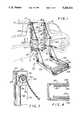
- FIG. 1is a perspective view showing a wheelchair lift embodying the present invention in a vehicle, the vehicle being shown in phantom;
- FIG. 2is an exploded isometric view of a preferred embodiment of the inner mounting structure and drive mechanism of the present invention
- FIG. 2Ais an enlarged, fragmentary perspective view of a portion of the support post showing the adjustable post laterally displaced from the main post for clarity.
- FIG. 3is a cross-sectional side view taken along line 3--3 of FIG. 1 showing the upper portion of the inner mounting structure and the chain-and-sprocket drive, as assembled;
- FIG. 4is a cross-sectional plan view taken along line 4--4 of FIG. 1 showing the interlocking adjustable post and main post.
- FIG. 1A wheelchair lift 10 embodying the features of the present invention is shown in FIG. 1 mounted to a vehicle V adjacent an access opening A.
- the lift 10includes a platform 12, an inner mounting structure 14 and a drive mechanism 15.
- the platform 12is secured to the mounting structure 14 by spaced apart vertical end posts 16 and spaced apart pairs of parallel arms 18.
- the lift 10is preferably of light weight aluminum alloy construction to reduce any affects on vehicle handling during driving.
- the mounting structure 14 of the lift 10is securely fastened to the inside bed or floor 20 of the vehicle V. It is also desirable, as will be described later, to secure the upper portion of the mounting structure to the vehicle either just above or adjacent to the sides of the access opening A.
- the mounting structure 14includes a pair of upright support posts 24 which together with the two pairs of parallel arms 18 and the two vertical end posts 16 form a pair of parallelogram linkages 22, one on each side and extendable outwardly from the access opening A of vehicle V.
- the linkages 22are designed to maintain the platform 12 in a substantially horizontal position when it is raised from the ground (or loading position) to the floor of the vehicle (or entry position) and vice versa. In other words, when the platform 12 is in the loading position, a wheelchair (not shown) can be rolled onto the platform.
- the liftis then actuated to move the platform to the entry position, from which the wheelchair is rolled onto the floor 20 of the vehicle V.
- the present inventionmay be used with any suitable linkage or other means that will move the platform between the loading position and the entry position.
- the platform 12may also be dimensioned to accommodate mobility devices other than a wheelchair, e.g. a gurney or a scooter. In either event, suitable safety features should be used on the platform, such as elongated guide rails 26 on each side of the platform and a pivotable end flap 28 which rotates from a horizontal position during loading of the platform to an upright position during raising or lowering of the platform.
- the inner mounting structure 14is shown having a base plate 30, the two support posts 24 and an alignment plate 36.
- Each support posthas a main post portion 32, 33 and an adjustable post portion 34, 35.
- the main posts and adjustable postsare channel shaped as shown.
- the support postsare also used to support miscellaneous electrical components 101, 102, 103 (see FIG. 1) for operating the lift.
- the base platehas perforations 40 to insert bolts for securing the mounting structure 14 to the floor of the vehicle and additional perforations 42 for attachment of a cover plate 44.
- the cover plate 44provides a bridge between the platform 12 and the floor of the vehicle (see FIG. 1).
- the main posts 32, 33may be secured to the base plate 30 via a pair of alignment blocks 46 inserted within the channels and secured by bolts 48.
- the channel forming the main post 32is shown having outwardly extending legs 50 and 52.
- the legs 50 and 52have a first set of pairs of aligned openings 60 at the upper portion 72 of the main post 32 which are used to secure the main post 32 to a lower portion 70 of the adjustable post 34.
- the openingsare spaced at predetermined intervals along the length of the main post to accommodate a variety of desired heights of the adjustable post.
- the channel forming the adjustable post 34is slightly larger than the channel forming the main post 32 so as to permit a sliding vertical movement of the adjustable post along the main post, as indicated by arrow V (see FIG. 2A).
- the channel forming the adjustable post 34is shown outwardly extending legs 54 and 56.
- the legs 54 and 56also have a second set of pairs of aligned openings 62 which are designed to cooperate with the first set of pairs of aligned openings 60 of the main post 32 when the main post 32 and adjustable post 34 are engaged.
- Upon determining the proper height of the top of the adjustable post 34it is releasably secured to the main post 32.
- the arrangement described aboveis also used for main post 33 and adjustable post 35.
- the adjustable postssufficiently overlap their respective main posts and that two bolts 66, 68 (See FIGS. 1 and 2A) be used for each connection.
- the two bolts 66, 68are 11 inches apart vertically in the standard position, as shown in FIG. 2A.
- the openings 60 and 62 in the posts 32 and 34 respectivelyare designed such that the adjustable post may be raised from the standard position (designated by x-markings on posts 33 and 35 of FIGS. 2 and 2A) by two inch increments (to accommodate a larger access opening of a vehicle) or lowered from the standard position in one inch increments (to accommodate mini vans).
- the standard positionis achieved when the posts 32 and 34 are in the vertical sliding relationship with the bolts 66 and 68 inserted through pairs of openings 62a and 60e, and 62e and 60a, respectively.
- subsets of pairs of openings 60b-60d, and 60f-60i of the main post 32are positioned respectively above and below the openings 60e so that the subset 60b-60d therabove is relatively spaced in one predetermined increment from the openings 60e and the subset 60f-60i therebelow is relatively spaced in another predetermined increment from the opening 60e.
- subsets 62b-62d, and 62f-62i of the adjustable posts 34are positioned in such predetermined increments, but respectively below and above the openings 62e, to mirror the subsets 60b-60d and 60f-60i.
- the one predetermined increment for the subsets 60b-60d and 62b-62dis two inches.
- the other predetermined increment for the subsets 60f-60i and 62f-62iis one inch. It is noted that as the adjustable post is extended, is less overlap between the adjustable post and the main post, therefore it is important that the bolts be a maximum distance apart to maximize the moment resistant capacity of the connection.
- an electric motor 80is shown in operative engagement with a gear box 82 having a cover 84.
- a driveshaft 86 operatively engaged with the gear box 82extends horizontally outward from the gear box 82 and has two sprockets 92, each receiving a chain 122.
- the driveshaft 86also supports the gear box.
- a torque plate 88is used as an additional connection to secure the gear box 22 to the adjustable post 34.
- U-shaped slots 76are formed for receiving the shaft 86.
- a bearing block 78 having an opening 79 through which the driveshaft passesis fastened between the legs 54, 56 of the channel forming the adjustable post 34 to serve as the support for the shaft.
- the bearing block 78may also be fastened to the alignment plate 36. The same arrangement is used for adjustable post 35.
- a chain-and-sprocket drive 90is shown in FIGS. 2 and 3 wherein an end piece 120 is fastened to the chain 122 and bolted to the alignment plate 36.
- the chain 122is allowed to fall within the channels forming adjustable post 34 and main post 32 and is then turned back up the channels to train over the sprocket 92 on the driveshaft 86.
- Fastening the end of the chain to the mounting structureprevents it from fully running out of the channel. Also, permitting the chain to double back on itself is preferable to simply permitting the chain to stack on to and off of itself wherein the chain may more easily get tangled.
- the chain 22After being trained around the sprocket 92, the chain 22 is secured to the vertical end post 16 for operating the parallelogram linkage 22 (see FIG. 1).
- a similar chain-and-sprocket driveis utilized with the other adjustable post 35 and secured to the other vertical end post.
- the chainmay pass vertically down through the vertical end post and be secured to the platform 12.
- the chain 122may be attached to the end flap 28 through a bar 38 (see FIG. 1) causing the end flap to move to its upright position whenever the lift is being raised or lowered.
- pieces 94 having slots 96 for closely receiving the sprocketsmay be used.
- elongate plastic tubes 98may be inserted into the channels forming the support posts 24 for receiving the chains prior to their training over the sprockets.
- the tubes 98may be secured at their upper ends to the alignment plate 36.
- Protective coversmade of ABS plastic may also be attached to the open sides of each channel to hide the tubes and chains from view and also to act as a dust cover.
- the above described embodiment of the present inventiondescribes a standardized lift that can be easily and quickly installed in a wide variety of vehicles. It can be adjusted to fit access openings provided in full-sized vans or mini-vans, vans with standard or raised door openings, as well as in certain buses and trucks. It may also be installed in free-standing curb side structures used to provide wheelchair users with access to buses at bus stops.
- the height of the access opening of the vehiclePrior to installing the lift, the height of the access opening of the vehicle is measured.
- the adjustable postsare then slid upwardly until the upper ends 74 of the adjustable posts 34 are at the desired height.
- Bolts 66, 68are then passed through the aligned openings 60 in the main posts and the corresponding aligned openings 62 in the adjustable posts and securely fastened.
- the adjustable postshave a tendency to tilt backward off of the main posts due to the weight of the motor and gear box concentrated on one end of the driveshaft.
- the main posts and adjustable postsare provided with an interlocking mechanism.
- the legs of the channel forming the main post 33are provided with angled protrusions 130 at their outer edges and the legs of the channel forming the adjustable post 35 are provided with corresponding bracketed portions 132 which cooperatively interlock the angled protrusions to prevent lateral movement of the adjustable posts while they are being raised or lowered past the main posts or when the adjustable posts are not otherwise secured to the main posts.
- Other shapes or structures for the interlocking mechanismmay be used provided lateral movement is prevented.
- FIG. 2one fastening method is depicted wherein a bracket 140 for securing the mounting structure to a vehicle is shown.
- the bracket 140includes a washer 142, a first perforated bar 144, a second perforated bar 146 and a T-fastener 148.
- the bracket 140is secured at one end to the upper portion 74 of the adjustable post 35 and at the other end to the door header or door post of the vehicle.
- the perforations in the first barmay be offset from center such that when the bar is secured to the adjustable post, it slants upwardly or downwardly, as necessary.
- the second perforated baracts as an extension piece, if needed.
- the same type of arrangementmay also be connected to the other adjustable post.
Landscapes
- Health & Medical Sciences (AREA)
- Public Health (AREA)
- Life Sciences & Earth Sciences (AREA)
- Animal Behavior & Ethology (AREA)
- General Health & Medical Sciences (AREA)
- Veterinary Medicine (AREA)
- Body Structure For Vehicles (AREA)
Abstract
Description
Claims (9)
Priority Applications (1)
| Application Number | Priority Date | Filing Date | Title |
|---|---|---|---|
| US07/962,149US5234311A (en) | 1991-07-17 | 1992-10-16 | Wheelchair lift with adjustable posts |
Applications Claiming Priority (2)
| Application Number | Priority Date | Filing Date | Title |
|---|---|---|---|
| US73167591A | 1991-07-17 | 1991-07-17 | |
| US07/962,149US5234311A (en) | 1991-07-17 | 1992-10-16 | Wheelchair lift with adjustable posts |
Related Parent Applications (1)
| Application Number | Title | Priority Date | Filing Date |
|---|---|---|---|
| US73167591AContinuation | 1991-07-17 | 1991-07-17 |
Publications (1)
| Publication Number | Publication Date |
|---|---|
| US5234311Atrue US5234311A (en) | 1993-08-10 |
Family
ID=27112280
Family Applications (1)
| Application Number | Title | Priority Date | Filing Date |
|---|---|---|---|
| US07/962,149Expired - LifetimeUS5234311A (en) | 1991-07-17 | 1992-10-16 | Wheelchair lift with adjustable posts |
Country Status (1)
| Country | Link |
|---|---|
| US (1) | US5234311A (en) |
Cited By (23)
| Publication number | Priority date | Publication date | Assignee | Title |
|---|---|---|---|---|
| US5672041A (en)* | 1994-12-22 | 1997-09-30 | Crow River Industries, Inc. | Collapsible, powered platform for lifting wheelchair |
| US5853282A (en)* | 1996-08-01 | 1998-12-29 | Ranger All Season Corporation | Scooter lift |
| US6089670A (en)* | 1999-02-10 | 2000-07-18 | Ralph R. Rogers | Detachable side dump body |
| USD440728S1 (en) | 1999-01-25 | 2001-04-17 | Phillip E. Schlangen | Wheelchair lift |
| US6309170B1 (en)* | 1999-08-17 | 2001-10-30 | Roger Vartanian | Vehicle wheelchair lift with mutually perpendicular pivot axes and parallelogram transport |
| US6435804B1 (en) | 1999-05-19 | 2002-08-20 | Mark Hutchins | Lifting apparatus |
| US20060045686A1 (en)* | 2004-07-14 | 2006-03-02 | Krichevsky Alexander | Mechanism for insertion of a wheelchair into a car |
| US20070183880A1 (en)* | 2006-02-03 | 2007-08-09 | Ricon Corp. | Slidably collapsible two arm wheel chair lift |
| US20070183881A1 (en)* | 2006-02-03 | 2007-08-09 | Ricon Corp. | Wheelchair lift with slidable support arm |
| US20080206030A1 (en)* | 2007-02-14 | 2008-08-28 | Reuille Bennett J | Lift apparatus mountable on a vehicle |
| WO2010144717A1 (en)* | 2009-06-12 | 2010-12-16 | Rs Drawings, Llc | Liftgate and mounting bracket system |
| US20110226558A1 (en)* | 2010-03-22 | 2011-09-22 | Fravel Gary L | Vehicle access system with powered lift |
| US8113760B1 (en) | 2008-05-12 | 2012-02-14 | Sean Schroll | Secure loading system |
| EP2641575A1 (en)* | 2012-03-21 | 2013-09-25 | Gustav Bruns Maschinenbau und Förderanlagen GmbH & Co. KG | Vehicle lift with pre-tensioning device |
| US20130251488A1 (en)* | 2012-03-21 | 2013-09-26 | Gustav Bruns Maschinenbau und Forderanlagen GmbH & Co. KG | Vehicle Lift |
| WO2013142280A1 (en)* | 2012-03-19 | 2013-09-26 | Ricon Corp. | Installation method and arrangement for a wheelchair lift arrangement |
| EP2818148A1 (en) | 2013-06-24 | 2014-12-31 | Autolift S.r.l. | Wheelchair lift |
| EP2641576B1 (en) | 2012-03-21 | 2015-04-22 | AMF-Bruns GmbH & Co. KG | Vehicle lift |
| US9101519B2 (en) | 2013-02-07 | 2015-08-11 | Dallas Smith Corporation | Leveling ramp for a wheelchair |
| US9139122B2 (en) | 2011-12-05 | 2015-09-22 | Miguel Esparza | Wheelchair transportation loading and storage apparatus |
| US9375369B2 (en) | 2012-03-21 | 2016-06-28 | Amf-Bruns Gmbh & Co. Kg | Vehicle lift with biasing device |
| US9555743B2 (en)* | 2015-05-22 | 2017-01-31 | Roy A. Schut | Driver lift device |
| US9862324B2 (en)* | 2015-05-22 | 2018-01-09 | Roy A. Schut | Driver lift device |
Citations (9)
| Publication number | Priority date | Publication date | Assignee | Title |
|---|---|---|---|---|
| US4003479A (en)* | 1975-06-04 | 1977-01-18 | Reyer William J | Hoist and transporting apparatus |
| US4168134A (en)* | 1978-03-01 | 1979-09-18 | Leo Pohl | Vehicle doorway lift |
| US4265586A (en)* | 1978-10-05 | 1981-05-05 | Jacques Couture | Lift assembly |
| USRE31178E (en)* | 1973-10-15 | 1983-03-15 | Ricon Corporation | Wheelchair lift |
| US4446587A (en)* | 1981-07-28 | 1984-05-08 | Jump Clarence E | Patient positioning device |
| US4563121A (en)* | 1983-02-22 | 1986-01-07 | Leyman Manufacturing Corp. | Cargo elevator system |
| US4915573A (en)* | 1988-09-06 | 1990-04-10 | Wapner Frank J | Stair lift |
| US4984955A (en)* | 1989-02-23 | 1991-01-15 | Mccullough Robert C | Lift apparatus |
| US4991810A (en)* | 1989-11-16 | 1991-02-12 | Michael Roman Bruno | Adjustable support base for mobile vehicle hoist |
- 1992
- 1992-10-16USUS07/962,149patent/US5234311A/ennot_activeExpired - Lifetime
Patent Citations (9)
| Publication number | Priority date | Publication date | Assignee | Title |
|---|---|---|---|---|
| USRE31178E (en)* | 1973-10-15 | 1983-03-15 | Ricon Corporation | Wheelchair lift |
| US4003479A (en)* | 1975-06-04 | 1977-01-18 | Reyer William J | Hoist and transporting apparatus |
| US4168134A (en)* | 1978-03-01 | 1979-09-18 | Leo Pohl | Vehicle doorway lift |
| US4265586A (en)* | 1978-10-05 | 1981-05-05 | Jacques Couture | Lift assembly |
| US4446587A (en)* | 1981-07-28 | 1984-05-08 | Jump Clarence E | Patient positioning device |
| US4563121A (en)* | 1983-02-22 | 1986-01-07 | Leyman Manufacturing Corp. | Cargo elevator system |
| US4915573A (en)* | 1988-09-06 | 1990-04-10 | Wapner Frank J | Stair lift |
| US4984955A (en)* | 1989-02-23 | 1991-01-15 | Mccullough Robert C | Lift apparatus |
| US4991810A (en)* | 1989-11-16 | 1991-02-12 | Michael Roman Bruno | Adjustable support base for mobile vehicle hoist |
Non-Patent Citations (3)
| Title |
|---|
| Ricon Classic brochure, published by Ricon Corporation, Nov. 1989.* |
| Ricon Mini Ride brochure, published by Ricon Corporation, Nov. 1989.* |
| Ricon Mini-Ride brochure, published by Ricon Corporation, Nov. 1989. |
Cited By (42)
| Publication number | Priority date | Publication date | Assignee | Title |
|---|---|---|---|---|
| US6053693A (en)* | 1994-12-22 | 2000-04-25 | Crow River Industries, Inc. | Collapsible, powered platform for lifting wheelchair |
| US6357992B1 (en) | 1994-12-22 | 2002-03-19 | Braun Crow River, Inc. | Collapsible, powered platform for lifting wheelchair |
| US5672041A (en)* | 1994-12-22 | 1997-09-30 | Crow River Industries, Inc. | Collapsible, powered platform for lifting wheelchair |
| US5853282A (en)* | 1996-08-01 | 1998-12-29 | Ranger All Season Corporation | Scooter lift |
| USD440728S1 (en) | 1999-01-25 | 2001-04-17 | Phillip E. Schlangen | Wheelchair lift |
| US6089670A (en)* | 1999-02-10 | 2000-07-18 | Ralph R. Rogers | Detachable side dump body |
| US6435804B1 (en) | 1999-05-19 | 2002-08-20 | Mark Hutchins | Lifting apparatus |
| US6309170B1 (en)* | 1999-08-17 | 2001-10-30 | Roger Vartanian | Vehicle wheelchair lift with mutually perpendicular pivot axes and parallelogram transport |
| US6648579B2 (en) | 1999-08-17 | 2003-11-18 | Roger Vartanian, Sr. | Platform lift |
| US7402019B2 (en)* | 2004-07-14 | 2008-07-22 | Krichevsky Alexander | Mechanism for insertion of a wheelchair into a car |
| US20060045686A1 (en)* | 2004-07-14 | 2006-03-02 | Krichevsky Alexander | Mechanism for insertion of a wheelchair into a car |
| US20070183880A1 (en)* | 2006-02-03 | 2007-08-09 | Ricon Corp. | Slidably collapsible two arm wheel chair lift |
| US20070183881A1 (en)* | 2006-02-03 | 2007-08-09 | Ricon Corp. | Wheelchair lift with slidable support arm |
| US7445416B2 (en) | 2006-02-03 | 2008-11-04 | Ricon Corp. | Wheelchair lift with slidable support arm |
| US7467917B2 (en) | 2006-02-03 | 2008-12-23 | Ricon Corporation | Slidably collapsible two arm wheelchair lift |
| US20090129906A1 (en)* | 2006-02-03 | 2009-05-21 | Ricon Corp. | Method of Stowing Wheelchair Lift |
| US7815413B2 (en) | 2006-02-03 | 2010-10-19 | Ricon Corp. | Method of stowing wheelchair lift |
| US20080206030A1 (en)* | 2007-02-14 | 2008-08-28 | Reuille Bennett J | Lift apparatus mountable on a vehicle |
| US8132997B2 (en)* | 2007-02-14 | 2012-03-13 | Razor Products, Inc. | Lift apparatus mountable on a vehicle |
| US8113760B1 (en) | 2008-05-12 | 2012-02-14 | Sean Schroll | Secure loading system |
| WO2010144717A1 (en)* | 2009-06-12 | 2010-12-16 | Rs Drawings, Llc | Liftgate and mounting bracket system |
| US20100313479A1 (en)* | 2009-06-12 | 2010-12-16 | Rs Drawings, Llc | Liftgate and mounting bracket system |
| US8282335B2 (en) | 2009-06-12 | 2012-10-09 | Rs Drawings, Llc | Liftgate and mounting bracket system |
| US20110226558A1 (en)* | 2010-03-22 | 2011-09-22 | Fravel Gary L | Vehicle access system with powered lift |
| US8308177B2 (en)* | 2010-03-22 | 2012-11-13 | Fravel Gary L | Vehicle access system with powered lift |
| US9139122B2 (en) | 2011-12-05 | 2015-09-22 | Miguel Esparza | Wheelchair transportation loading and storage apparatus |
| WO2013142280A1 (en)* | 2012-03-19 | 2013-09-26 | Ricon Corp. | Installation method and arrangement for a wheelchair lift arrangement |
| US20150044006A1 (en)* | 2012-03-19 | 2015-02-12 | Ricon Corp. | Installation method and arrangement for a wheelchair lift arrangment |
| JP2015510821A (en)* | 2012-03-19 | 2015-04-13 | ライコン コーポレイション | Installation method and apparatus for wheelchair lift device |
| EP2827821A4 (en)* | 2012-03-19 | 2015-11-11 | Ricon Corp | INSTALLATION METHOD AND DEVICE FOR WHEELCHAIR RAISING PLATFORM SYSTEM |
| US9943454B2 (en)* | 2012-03-19 | 2018-04-17 | Ricon Corp. | Installation method and arrangement for a wheelchair lift arrangement |
| AU2013235424B2 (en)* | 2012-03-19 | 2017-06-01 | Ricon Corp. | Installation method and arrangement for a wheelchair lift arrangement |
| US9814635B2 (en)* | 2012-03-21 | 2017-11-14 | Amf-Bruns Gmbh & Co. Kg | Vehicle lift |
| US20130251488A1 (en)* | 2012-03-21 | 2013-09-26 | Gustav Bruns Maschinenbau und Forderanlagen GmbH & Co. KG | Vehicle Lift |
| EP2641576B1 (en) | 2012-03-21 | 2015-04-22 | AMF-Bruns GmbH & Co. KG | Vehicle lift |
| EP2641575A1 (en)* | 2012-03-21 | 2013-09-25 | Gustav Bruns Maschinenbau und Förderanlagen GmbH & Co. KG | Vehicle lift with pre-tensioning device |
| US9375369B2 (en) | 2012-03-21 | 2016-06-28 | Amf-Bruns Gmbh & Co. Kg | Vehicle lift with biasing device |
| US9101519B2 (en) | 2013-02-07 | 2015-08-11 | Dallas Smith Corporation | Leveling ramp for a wheelchair |
| EP2818148A1 (en) | 2013-06-24 | 2014-12-31 | Autolift S.r.l. | Wheelchair lift |
| US9974702B2 (en) | 2013-06-24 | 2018-05-22 | Autolift S.R.L. | Wheelchair lift |
| US9862324B2 (en)* | 2015-05-22 | 2018-01-09 | Roy A. Schut | Driver lift device |
| US9555743B2 (en)* | 2015-05-22 | 2017-01-31 | Roy A. Schut | Driver lift device |
Similar Documents
| Publication | Publication Date | Title |
|---|---|---|
| US5234311A (en) | Wheelchair lift with adjustable posts | |
| US6802095B1 (en) | Ramp assembly having a lift and lock mechanism | |
| US2944852A (en) | Vertically collapsible and telescoping trailer body | |
| US5941342A (en) | Folding staircase | |
| US4664584A (en) | Rotary wheelchair lift | |
| US4869030A (en) | Porch adapted for use with a mobile living unit | |
| US5474189A (en) | Bicycle lift and storage system | |
| US6793269B2 (en) | Door assembly for improved vehicle access | |
| US6170502B1 (en) | Collapsible portable camper system | |
| US6234740B1 (en) | Vehicle cargo lift | |
| US6874597B2 (en) | Vehicle sleeper compartment bunk bed ladder | |
| WO2019214873A1 (en) | Foldable ramp for wheelchair access to a passenger car rear door | |
| JPH06507357A (en) | Truck van cover with improved access means | |
| US5215349A (en) | Support system for flexible side walls for cargo vehicles | |
| US20050239586A1 (en) | Bed lift | |
| US7036548B2 (en) | Method and apparatus for positioning a sectional door relative to an opening | |
| US4138023A (en) | Vehicle wheelchair lift | |
| US4566842A (en) | Wheelchair dockage and storage system | |
| US5727656A (en) | Vehicle lift apparatus | |
| US6048156A (en) | Vehicle parking device | |
| JP2005526646A (en) | Lamp assembly with lift / lock mechanism | |
| KR101323961B1 (en) | Transforteable Kiosk | |
| KR19990036162A (en) | Folding frame device | |
| CN117999394A (en) | Multistage formula camping room | |
| US4226462A (en) | Car door transfer seat for handicapped persons |
Legal Events
| Date | Code | Title | Description |
|---|---|---|---|
| STCF | Information on status: patent grant | Free format text:PATENTED CASE | |
| FPAY | Fee payment | Year of fee payment:4 | |
| AS | Assignment | Owner name:ANTARES LEVERAGED CAPITAL CORP., ILLINOIS Free format text:SECURITY AGREEMENT;ASSIGNOR:RICON CORP.;REEL/FRAME:009289/0355 Effective date:19980702 | |
| REMI | Maintenance fee reminder mailed | ||
| FPAY | Fee payment | Year of fee payment:8 | |
| SULP | Surcharge for late payment | Year of fee payment:7 | |
| AS | Assignment | Owner name:RICON CORP., CALIFORNIA Free format text:RELEASE OF SECURITY INTEREST;ASSIGNOR:ANTARES CAPITAL CORPORATION (FORMERLY KNOWN AS ANTARES LEVERAGED CAPITAL CORP.);REEL/FRAME:013608/0314 Effective date:20021212 Owner name:MERRILL LYNCH CAPITAL, A DIVISION OF MERRILL LYNCH Free format text:SECURITY INTEREST;ASSIGNOR:RICON CORP.;REEL/FRAME:013589/0496 Effective date:20021213 | |
| FEPP | Fee payment procedure | Free format text:PAYOR NUMBER ASSIGNED (ORIGINAL EVENT CODE: ASPN); ENTITY STATUS OF PATENT OWNER: LARGE ENTITY | |
| FPAY | Fee payment | Year of fee payment:12 | |
| FEPP | Fee payment procedure | Free format text:PAT HOLDER NO LONGER CLAIMS SMALL ENTITY STATUS, ENTITY STATUS SET TO UNDISCOUNTED (ORIGINAL EVENT CODE: STOL); ENTITY STATUS OF PATENT OWNER: LARGE ENTITY | |
| AS | Assignment | Owner name:RICON CORP.,CALIFORNIA Free format text:PATENT RELEASE AND REASSIGNMENT;ASSIGNOR:MERRILL LYNCH CAPITAL, A DIVISION OF MERRILL LYNCH BUSINESS FINANCIAL SERVICES, INC.;REEL/FRAME:024312/0521 Effective date:20070608 |