US5234232A - Bookbinding apparatus and method of binding sheets - Google Patents
Bookbinding apparatus and method of binding sheetsDownload PDFInfo
- Publication number
- US5234232A US5234232AUS07/816,029US81602991AUS5234232AUS 5234232 AUS5234232 AUS 5234232AUS 81602991 AUS81602991 AUS 81602991AUS 5234232 AUS5234232 AUS 5234232A
- Authority
- US
- United States
- Prior art keywords
- strip
- studs
- opening
- locking
- stud
- Prior art date
- Legal status (The legal status is an assumption and is not a legal conclusion. Google has not performed a legal analysis and makes no representation as to the accuracy of the status listed.)
- Expired - Fee Related
Links
Images

Classifications
- B—PERFORMING OPERATIONS; TRANSPORTING
- B42—BOOKBINDING; ALBUMS; FILES; SPECIAL PRINTED MATTER
- B42F—SHEETS TEMPORARILY ATTACHED TOGETHER; FILING APPLIANCES; FILE CARDS; INDEXING
- B42F13/00—Filing appliances with means for engaging perforations or slots
- B42F13/12—Filing appliances with means for engaging perforations or slots with pillars, posts, rods, or tubes
- B42F13/14—Filing appliances with means for engaging perforations or slots with pillars, posts, rods, or tubes with clamping or locking means
Definitions
- the present inventionrelates to the field of bookbinding, and is specifically concerned with bookbinding strips for binding together perforated sheets and the like, a method of binding perforated sheets with the bookbinding strips, and a book bound together with the bookbinding strips.
- a variety of methods and bookbinding devicesare known for holding a collection of pages or sheets together to form books, filings, price lists, catalogs, booklets, and the like.
- spiral devices and methods of bookbindingdisclosed in Emmer U.S. Pat. Nos. 2,099,881 and 2,450,785, Mevi U.S. Pat. No. 2,116,078, and Friedman U.S. Pat. No. 4,374,627.
- Another example of the spiral deviceis the GBC (General Binding Corporation) plastic spiral comb.
- the spiral devicesrequire large storage areas to store the different sizes (sometimes 16 different sizes) of combs, and this is a disadvantage.
- Another bookbinding deviceis the loose-leaf binder, which uses spring-loaded semi-circular snap rings to hold a collection of pages together.
- An advantage of the loose-leaf binderis that the collection of pages held by the loose-leaf binder may be easily updated by opening the snap rings, removing the old page(s) from the opened snap rings, adding the updated page(s) to the opened snap rings, and closing the snap rings.
- Disadvantages of the loose-leaf binderinclude: (1) the fingers of the snap rings frequently become misaligned resulting in loss of or damage to the pages held in the loose-leaf binder, (2) loose-leaf binders are generally bulky since such binders have a ring mechanism, a spine panel, a front cover, and a back cover, and (3) the size of a standard loose-leaf binder is not adjustable to fit the thickness of the collection of pages being held in the loose-leaf binder.
- Another deviceis a folding post binder, which has metal prongs that may be bent over and moveable slides or covers that hold the metal prongs in place.
- a disadvantage of the folding post binderis that the edges of the metal prongs sometimes are sharp, which is dangerous.
- Affingaard et al. U.S. Pat. Nos. Re 28,202, 4,369,013, and 4,620,724disclose rigid plastic binding strips. Smooth studs formed on a first strip are inserted through perforated sheets and then through holes in a second strip. Then, pressure and/or heat is applied to the end of the studs to form a head which locks the strips and the sheets therebetween in assembled position.
- Affingaard et al. binding stripsrequire expensive mechanical equipment to create the heads on the studs, and these strips provide a permanent-type binding rather than an updatable-type binding.
- Affingaard et al. U.S. Pat. Nos. 4,674,906 and 4,685,700disclose an updatable-type binding. Smooth studs formed on a first strip are inserted through perforated sheets and then through holes in a second strip. Then, the ends of the studs projecting from the holes in the second strip are bent over at a right angle into a groove to hold the first strip to the second strip. Binding thick books with such a binding is difficult because locking with the studs requires that the studs project far enough out of the holes in the second strip to permit bending of the studs.
- Baumgart U.S. Pat. No. 950,768 and Giulie U.S. Pat. No. 3,970,331also disclose binding strips. Studs formed on a first strip have teeth that engage a lip in a second strip to lock the first strip to the second strip. These ratchet-type devices require considerable and evenly distributed force to pass the studs of the first strip through the second strip, and once the devices are locked it is very difficult, if not impossible, to disengage the first strip from the second strip.
- Another object of the inventionis to provide a bookbinding apparatus that is easy to assemble and disassemble and that does not require expensive machinery to use.
- Another object of the inventionis to provide a bookbinding apparatus that overcomes some, and possibly all, of the disadvantages of the prior art mentioned above.
- a bookbinding apparatusfor binding together perforated sheets and the like that comprises a first strip and a second strip.
- Spaced-apart studsare formed on and extend from the first strip, and spaced-apart locking caps are formed and extend around each stud.
- Spaced-apart first openingsare formed in and extend through the second strip, and each first opening is aligned with a corresponding stud of the first strip.
- Each first openinghas a size larger than a cross-section of the corresponding stud of the first strip to freely receive that stud.
- Locking meansare formed on the second strip for locking the studs to the second strip, and the locking means include second openings formed in and extending through the second strip.
- Each second openingis located next to and in partial contact with a first opening, and each second opening has a size smaller than the cross-section of the studs at a locking cap but larger than or equal to the cross-section of the studs between locking caps such that the second strip after receiving studs of the first strip with the first openings in the second strip locks the studs of the first strip to the second strip by being slid sideways forcing the second openings of the second strip to surround the studs below a locking cap.
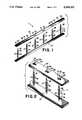
- FIG. 1is a view in perspective of a bookbinding apparatus constructed in accordance with the invention
- FIG. 2is another view in perspective of a bookbinding apparatus constructed in accordance with the invention.
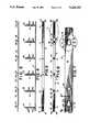
- FIG. 3is a view in side elevation of a second strip constructed in accordance with the invention.
- FIG. 4is a view in side elevation of a first strip constructed in accordance with the invention.
- FIG. 5is a view in top plan of the first strip shown in FIG. 4;
- FIG. 6is a view in top plan of the second strip shown in FIG. 3;
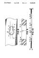
- FIG. 7is a fragmentary enlargement taken as indicated by the circle 7 which appears in FIG. 6;
- FIG. 8is a fragmentary enlargement taken as indicated by the circle 8 which appears in FIG. 7;
- FIG. 9is a view in cross-section taken along the lines and arrows 9--9 of FIG. 7;
- FIG. 10is a view in bottom plan of the second strip shown in FIG. 3;
- FIGS. 11a, 11b, and 11care views in cross-section illustrating the method of binding a book in accordance with the invention.
- FIGS. 12a, 12b, and 12care partial views in top plan of the second strip which illustrate the sequence of how the second strip is locked onto a stud.
- FIG. 13is a view in perspective of a book constructed in accordance with the invention.
- FIGS. 1 and 2there is shown in FIGS. 1 and 2 a bookbinding apparatus 11 for binding together perforated sheets and the like, which comprises a first strip 13, and a second strip 15.
- Spaced-apart studs 17are formed on and are integral with first strip 13, and studs 17 extend outwardly from first strip 13 to receive the sheets.
- Each stud 17has a tapered end 18 to promote easy penetration of studs 17 through the perforations in the sheets being bound.
- a series of locking caps or 19are formed on and extend around each stud 17.
- Second strip 15is provided with a series of spaced-apart first openings 21 that are formed in and that extend through second strip 15. Each first opening 21 is aligned with a corresponding stud 17 of first strip 13, and each first opening 21 has a size larger than the cross-section of the corresponding stud 17 of first strip 13 to freely receive said stud 17.
- a series of second openings 23also are formed in and extend through second strip 15 for locking studs 17 to second strip 15.
- Each second opening 23is located next to and in partial contact with a first opening 21.
- Each second opening 23has a size smaller than the cross-section of the studs 17 at a locking cap 19 but larger than or equal to the cross-section of the studs 17 between locking caps 19 such that second strip 15, after receiving studs 17 with its first openings 21, locks the studs 17 of first strip 13 to second strip 15 by being slid sideways forcing the second openings 23 in second strip 15 to surround studs 17 below a locking cap 19.
- a series of recesses 25is formed in the outer surface 27 of second strip 15 around the periphery of each first opening 21 and each second opening 23.
- Each recess 25forms a ledge 29, and a locking cap 19 rests against the portion of ledge 29 surrounding second opening 23 when stud 17 is in locking position, that is, when a stud 17 is positioned in second opening 23.
- ledge 29is slightly wider than the flanged portion of locking cap 19.
- the portion of each recess 25 surrounding each second opening 23is sized to receive a locking cap 19 so that the locking cap 19 is countersunk into second strip 15 when stud 17 is positioned in second opening 23.
- each first pinch-point segment 31is spaced from each opposing second pinch-point segment 33 by a distance slightly smaller than the cross-section of stud 17 between locking caps 19 to aid in locking second strip 15 to stud 17.
- pinch-point segments 31 and 33are pushed away from one another as stud 17 passes between pinch-point segments 31 and 33 and into second opening 23, and pinch-point segments 31 and 33 flex back toward their original positions as stud 17 moves into second opening 23 to hold stud 17 in second opening 23, the distance between pinch-point segments 31 and 33 again becoming smaller than the cross-section of stud 17 between locking caps 19.
- stud 17is resilient, stud 17 is squeezed past pinch-point segments 31 and 33, stud 17 rebounding to its original cross-section when received in second opening 23 and being held in second opening 23 by pinch-point segments 31 and 33.
- the distance separating pinch-point segment 31 from pinch-point segment 33may be the same as or larger than the cross-section of a stud 17 between locking caps 19.
- Holes 35are formed in second strip 15 for engaging a locating pin in a bookbinding machine such as the bookbinding machine disclosed in Andugaard U.S. Pat. No. 3,756,625 when a bookbinding machine is used to assemble the book, to keep the sheets being bound and strips 13 and 15 in alignment with one another.
- a bookbinding machinesuch as the bookbinding machine disclosed in Andugaard U.S. Pat. No. 3,756,625 when a bookbinding machine is used to assemble the book, to keep the sheets being bound and strips 13 and 15 in alignment with one another.
- first strip 13is provided with rounded corners 37 and second strip 15 is provided with rounded corners 39.
- first strip 13 and second strip 15are then pressed tightly towards each other, and second strip 15 is slid sideways to force the second opening 23 in second strip 15 to surround the corresponding studs 17 below a locking cap 19, thereby locking the second strip 15 to studs 17.
- FIGS. 11a and 12bshow second strip 15 receiving a stud 17 in first opening 21 before second strip 15 is locked on stud 17 and
- FIGS. 11b and 12cshow second strip 15 locked onto stud 17 after second strip 15 has been slid to the left in the drawings.
- each stud 17may be cut or clipped above the locking cap 19 positioned against the outer surface of second strip 15 to remove any excess portion of each stud 17 and provide a smooth finish. Since said locking cap 19 sits in recess 25, when each stud 17 is so cut, the top portion of the outermost locking cap 19 remaining on stud 17 is flush with the outer surface of strip 15.
- heat from a heat source such as an ironmay be applied to each locking cap 19 positioned against the outer surface of second strip 15, that is, to the outermost locking cap 19 remaining on stud 17 after cutting, to melt each of said locking caps 19 to second strip 15 to solidify the bind.
- a bookmay be disassembled by sliding second strip 15 sideways to force studs 17 into first openings 21, sliding second strip 15 off studs 17, and removing the perforated sheets from studs 17. Accordingly, the book may be updated by replacing old pages with new pages, and then easily reassembled.
- the bookmay be disassembled as explained above and then reassembled with fewer sheets. Any excess portion of each stud 17 may be cut or clipped off to provide a smooth finish.
- the bookmay be disassembled as described above and then reassembled as described above using a new first strip 13.
- strips 13 and 15are molded from a resilient thermoplastic material.
- strips 13 and 15maybe made of other materials, such as steel, aluminum, wood, and the like.
- a book, constructed in accordance with the invention, such as a book 43 shown in FIG. 13,comprises a plurality of sheets each having spaced-apart holes spaced along a spine edge of each sheet, and the bookbinding apparatus 11 mounted on the spine edges of the sheets.
- the sheetsmay be paper, plastic, cardboard, fabric, and the like.
- the method of binding together sheets with the inventive bookbinding apparatus 11is quick and easy, and the method requires no expensive equipment or technical knowledge. Further, books bound using the inventive method may be updated quickly and easily.
- Bookbinding apparatus 11is preferably made of inexpensive thermoplastic material, so it may be made by injection molding in large quantities at low cost.
- Bookbinding apparatus 11is very durable and attractive, and bookbinding apparatus 11 may be molded in a variety of colors.
- each sheet bound in bookbinding apparatus 11may be viewed since bookbinding apparatus 11 may be bound close to the edge of each sheet so as not to obscure information appearing on the sheets.
- Bookbinding apparatus 11tightly binds sheets together so the problem of sheets being accidently torn out of the binding during handling is practically eliminated.
- Bookbinding apparatus 11may be used to bind books having a thickness from thin to thick, and since strips 13 and 15 lie snugly against the outer sheets of books constructed in accordance with the invention, such books are easier to file and to mail than typical loose-leaf type bookbindings since the books constructed in accordance with the invention take up less space than the typical loose-leaf type bookbindings.
- bookbinding apparatus 11is disassembled easily to permit sheets to be added or removed from the book, and after updating, bookbinding apparatus 11 is easily reassembled.
- said booksmay be constructed almost anywhere, such as in an airplane or train, or in school, the office, or the home.
Landscapes
- Sheet Holders (AREA)
Abstract
Description
1. Field of the Invention
The present invention relates to the field of bookbinding, and is specifically concerned with bookbinding strips for binding together perforated sheets and the like, a method of binding perforated sheets with the bookbinding strips, and a book bound together with the bookbinding strips.
2. Description of the Prior Art
A variety of methods and bookbinding devices are known for holding a collection of pages or sheets together to form books, filings, price lists, catalogs, booklets, and the like.
For example, there are spiral devices and methods of bookbinding disclosed in Emmer U.S. Pat. Nos. 2,099,881 and 2,450,785, Mevi U.S. Pat. No. 2,116,078, and Friedman U.S. Pat. No. 4,374,627. Another example of the spiral device is the GBC (General Binding Corporation) plastic spiral comb. The spiral devices require large storage areas to store the different sizes (sometimes 16 different sizes) of combs, and this is a disadvantage.
Another bookbinding device is the loose-leaf binder, which uses spring-loaded semi-circular snap rings to hold a collection of pages together. An advantage of the loose-leaf binder is that the collection of pages held by the loose-leaf binder may be easily updated by opening the snap rings, removing the old page(s) from the opened snap rings, adding the updated page(s) to the opened snap rings, and closing the snap rings. Disadvantages of the loose-leaf binder include: (1) the fingers of the snap rings frequently become misaligned resulting in loss of or damage to the pages held in the loose-leaf binder, (2) loose-leaf binders are generally bulky since such binders have a ring mechanism, a spine panel, a front cover, and a back cover, and (3) the size of a standard loose-leaf binder is not adjustable to fit the thickness of the collection of pages being held in the loose-leaf binder.
Another device is a folding post binder, which has metal prongs that may be bent over and moveable slides or covers that hold the metal prongs in place. A disadvantage of the folding post binder is that the edges of the metal prongs sometimes are sharp, which is dangerous.
Abildgaard et al. U.S. Pat. Nos. Re 28,202, 4,369,013, and 4,620,724 disclose rigid plastic binding strips. Smooth studs formed on a first strip are inserted through perforated sheets and then through holes in a second strip. Then, pressure and/or heat is applied to the end of the studs to form a head which locks the strips and the sheets therebetween in assembled position. Abildgaard et al. binding strips require expensive mechanical equipment to create the heads on the studs, and these strips provide a permanent-type binding rather than an updatable-type binding.
Abildgaard et al. U.S. Pat. Nos. 4,674,906 and 4,685,700 disclose an updatable-type binding. Smooth studs formed on a first strip are inserted through perforated sheets and then through holes in a second strip. Then, the ends of the studs projecting from the holes in the second strip are bent over at a right angle into a groove to hold the first strip to the second strip. Binding thick books with such a binding is difficult because locking with the studs requires that the studs project far enough out of the holes in the second strip to permit bending of the studs.
Baumgart U.S. Pat. No. 950,768 and Giulie U.S. Pat. No. 3,970,331 also disclose binding strips. Studs formed on a first strip have teeth that engage a lip in a second strip to lock the first strip to the second strip. These ratchet-type devices require considerable and evenly distributed force to pass the studs of the first strip through the second strip, and once the devices are locked it is very difficult, if not impossible, to disengage the first strip from the second strip.
It is an object of the invention to provide a bookbinding apparatus for binding together perforated sheets and the like.
Another object of the invention is to provide a bookbinding apparatus that is easy to assemble and disassemble and that does not require expensive machinery to use.
Another object of the invention is to provide a bookbinding apparatus that overcomes some, and possibly all, of the disadvantages of the prior art mentioned above.
These and other objects are accomplished by providing a bookbinding apparatus for binding together perforated sheets and the like that comprises a first strip and a second strip. Spaced-apart studs are formed on and extend from the first strip, and spaced-apart locking caps are formed and extend around each stud. Spaced-apart first openings are formed in and extend through the second strip, and each first opening is aligned with a corresponding stud of the first strip. Each first opening has a size larger than a cross-section of the corresponding stud of the first strip to freely receive that stud. Locking means are formed on the second strip for locking the studs to the second strip, and the locking means include second openings formed in and extending through the second strip. Each second opening is located next to and in partial contact with a first opening, and each second opening has a size smaller than the cross-section of the studs at a locking cap but larger than or equal to the cross-section of the studs between locking caps such that the second strip after receiving studs of the first strip with the first openings in the second strip locks the studs of the first strip to the second strip by being slid sideways forcing the second openings of the second strip to surround the studs below a locking cap.
FIG. 1 is a view in perspective of a bookbinding apparatus constructed in accordance with the invention;
FIG. 2 is another view in perspective of a bookbinding apparatus constructed in accordance with the invention;
FIG. 3 is a view in side elevation of a second strip constructed in accordance with the invention;
FIG. 4 is a view in side elevation of a first strip constructed in accordance with the invention;
FIG. 5 is a view in top plan of the first strip shown in FIG. 4;
FIG. 6 is a view in top plan of the second strip shown in FIG. 3;
FIG. 7 is a fragmentary enlargement taken as indicated by the circle 7 which appears in FIG. 6;
FIG. 8 is a fragmentary enlargement taken as indicated by thecircle 8 which appears in FIG. 7;
FIG. 9 is a view in cross-section taken along the lines andarrows 9--9 of FIG. 7;
FIG. 10 is a view in bottom plan of the second strip shown in FIG. 3;
FIGS. 11a, 11b, and 11c are views in cross-section illustrating the method of binding a book in accordance with the invention;
FIGS. 12a, 12b, and 12c are partial views in top plan of the second strip which illustrate the sequence of how the second strip is locked onto a stud; and
FIG. 13 is a view in perspective of a book constructed in accordance with the invention.
Turning to the drawings, there is shown in FIGS. 1 and 2 a bookbinding apparatus 11 for binding together perforated sheets and the like, which comprises afirst strip 13, and asecond strip 15.
Spaced-apart studs 17 are formed on and are integral withfirst strip 13, andstuds 17 extend outwardly fromfirst strip 13 to receive the sheets. Eachstud 17 has atapered end 18 to promote easy penetration ofstuds 17 through the perforations in the sheets being bound.
A series of locking caps or 19 are formed on and extend around eachstud 17.
A series ofsecond openings 23 also are formed in and extend throughsecond strip 15 for lockingstuds 17 tosecond strip 15. Eachsecond opening 23 is located next to and in partial contact with afirst opening 21. Eachsecond opening 23 has a size smaller than the cross-section of thestuds 17 at a lockingcap 19 but larger than or equal to the cross-section of thestuds 17 between locking caps 19 such thatsecond strip 15, after receivingstuds 17 with itsfirst openings 21, locks thestuds 17 offirst strip 13 tosecond strip 15 by being slid sideways forcing thesecond openings 23 insecond strip 15 to surroundstuds 17 below a lockingcap 19.
As seen in FIGS. 2, 3, and 6, and more particularly in FIGS. 7, 8 and 9, a series ofrecesses 25 is formed in theouter surface 27 ofsecond strip 15 around the periphery of eachfirst opening 21 and eachsecond opening 23. Eachrecess 25 forms aledge 29, and a lockingcap 19 rests against the portion ofledge 29 surroundingsecond opening 23 whenstud 17 is in locking position, that is, when astud 17 is positioned insecond opening 23. Preferably,ledge 29 is slightly wider than the flanged portion of lockingcap 19. Also, the portion of eachrecess 25 surrounding eachsecond opening 23 is sized to receive alocking cap 19 so that the lockingcap 19 is countersunk intosecond strip 15 whenstud 17 is positioned insecond opening 23.
Referring to FIGS. 7, 8 and 12, opposing first and second pinch-point segments second strip 15 where eachfirst opening 21 overlaps eachsecond opening 23. Preferably, when thefirst strip 13, includingstuds 17, and/or thesecond strip 15 are made of a resilient material, each first pinch-point segment 31 is spaced from each opposing second pinch-point segment 33 by a distance slightly smaller than the cross-section ofstud 17 between locking caps 19 to aid in lockingsecond strip 15 tostud 17. That is, whensecond strip 15 is resilient, pinch-point segments stud 17 passes between pinch-point segments second opening 23, and pinch-point segments stud 17 moves intosecond opening 23 to holdstud 17 insecond opening 23, the distance between pinch-point segments stud 17 between locking caps 19. Similarly, whenstud 17 is resilient,stud 17 is squeezed past pinch-point segments stud 17 rebounding to its original cross-section when received insecond opening 23 and being held insecond opening 23 by pinch-point segments
However, no matter what material strips 13 and 15 are made of, the distance separating pinch-point segment 31 from pinch-point segment 33 may be the same as or larger than the cross-section of astud 17 between locking caps 19.
For cosmetic reasons,first strip 13 is provided withrounded corners 37 andsecond strip 15 is provided withrounded corners 39.
In use, as shown in FIGS. 11 and 12,studs 17 offirst strip 13 are inserted through corresponding perforations in thesheets 41 being bound.
Then,studs 17 are inserted through correspondingfirst openings 21 insecond strip 15 tosandwich sheets 41 betweenfirst strip 13 andsecond strip 15.
Preferably,first strip 13 andsecond strip 15 are then pressed tightly towards each other, andsecond strip 15 is slid sideways to force thesecond opening 23 insecond strip 15 to surround the correspondingstuds 17 below a lockingcap 19, thereby locking thesecond strip 15 tostuds 17. FIGS. 11a and 12b showsecond strip 15 receiving astud 17 infirst opening 21 beforesecond strip 15 is locked onstud 17 and FIGS. 11b and 12c showsecond strip 15 locked ontostud 17 aftersecond strip 15 has been slid to the left in the drawings.
Whenstuds 17 are positioned insecond openings 23,studs 17 are locked tosecond strip 15, thereby bindingsheets 41 together, becausesheets 41, after being compressed together betweenfirst strip 13 andsecond strip 15, push outwardly againstfirst strip 13 andsecond strip 15, because force is required to slidesecond strip 15 sideways to disengage from the locking position, and because force is required to passstud 17 between the pinch-point segments first opening 21 when the distance between the opposing pinch-point segments stud 17 between locking caps 19.
As shown in FIG. 11b, eachstud 17 may be cut or clipped above the lockingcap 19 positioned against the outer surface ofsecond strip 15 to remove any excess portion of eachstud 17 and provide a smooth finish. Since said lockingcap 19 sits inrecess 25, when eachstud 17 is so cut, the top portion of theoutermost locking cap 19 remaining onstud 17 is flush with the outer surface ofstrip 15.
Optionally, heat from a heat source such as an iron may be applied to each lockingcap 19 positioned against the outer surface ofsecond strip 15, that is, to theoutermost locking cap 19 remaining onstud 17 after cutting, to melt each of said locking caps 19 tosecond strip 15 to solidify the bind.
If the heating step is not used in binding the sheets together, a book may be disassembled by slidingsecond strip 15 sideways to forcestuds 17 intofirst openings 21, slidingsecond strip 15 offstuds 17, and removing the perforated sheets fromstuds 17. Accordingly, the book may be updated by replacing old pages with new pages, and then easily reassembled.
If it is desired to reduce the number of sheets in a book bound in accordance with the invention, the book may be disassembled as explained above and then reassembled with fewer sheets. Any excess portion of eachstud 17 may be cut or clipped off to provide a smooth finish.
If it is desired to add sheets to a book assembled in accordance with the invention, the book may be disassembled as described above and then reassembled as described above using a newfirst strip 13.
Preferably, strips 13 and 15 are molded from a resilient thermoplastic material. However, strips 13 and 15 maybe made of other materials, such as steel, aluminum, wood, and the like.
A book, constructed in accordance with the invention, such as abook 43 shown in FIG. 13, comprises a plurality of sheets each having spaced-apart holes spaced along a spine edge of each sheet, and the bookbinding apparatus 11 mounted on the spine edges of the sheets. The sheets may be paper, plastic, cardboard, fabric, and the like.
Unlike many known bookbinding strips, no expensive machinery is needed to mount bookbinding apparatus 11 onto the sheets. Further, the use of heat and messy glues is not needed.
The method of binding together sheets with the inventive bookbinding apparatus 11 is quick and easy, and the method requires no expensive equipment or technical knowledge. Further, books bound using the inventive method may be updated quickly and easily.
Bookbinding apparatus 11 is preferably made of inexpensive thermoplastic material, so it may be made by injection molding in large quantities at low cost.
Bookbinding apparatus 11 is very durable and attractive, and bookbinding apparatus 11 may be molded in a variety of colors.
Substantially the entire surface area of each sheet bound in bookbinding apparatus 11 may be viewed since bookbinding apparatus 11 may be bound close to the edge of each sheet so as not to obscure information appearing on the sheets.
Bookbinding apparatus 11 tightly binds sheets together so the problem of sheets being accidently torn out of the binding during handling is practically eliminated.
Bookbinding apparatus 11 may be used to bind books having a thickness from thin to thick, and sincestrips
Further, if updating of a book is necessary, bookbinding apparatus 11 is disassembled easily to permit sheets to be added or removed from the book, and after updating, bookbinding apparatus 11 is easily reassembled.
Since very little space is needed to assemble a book constructed in accordance with the invention, said books may be constructed almost anywhere, such as in an airplane or train, or in school, the office, or the home.
Claims (17)
1. A book comprising
a plurality of sheets each having spaced-apart holes spaced along a spine edge of each sheet, and
a bookbinding device mounted on the spine edges of the sheets for binding together the sheets,
the bookbinding device including
a first strip,
spaced-apart studs formed on and extending from the first strip through the spaced-apart holes in the sheets,
spaced-apart locking caps formed on and extending around each stud,
a second strip,
spaced-apart first openings formed in and extending through the second strip,
each first opening being aligned with a corresponding stud of the first strip and each first opening having a size larger than the cross-section of the corresponding stud of the first strip to freely receive said stud,
the first strip and/or the second strip being made of a resilient material, and
locking means formed on the second strip for locking the studs to the second strip,
the locking means including second openings formed in and extending through the second strip,
each second opening being located next to and in partial contact with a first opening, and each second opening having a size smaller than the cross-section of the studs at a locking cap but larger than or equal to the cross-section of the studs between locking caps such that the second strip after receiving studs of the first strip with the first openings in the second strip locks the studs of the first strip to the second strip by being slid sideways forcing the second openings in the second strip to surround the studs below a locking cap, and
a series of first pinch-point segments formed in the second strip, and
a series of second pinch-point segments formed in the second strip,
each first pinch-point segment being located opposite a corresponding second pinch-point segment where each first opening overlaps each second opening at a distance smaller than the cross-section of the studs between locking caps.
2. The book of claim 1,
the second strip having an inner surface and an outer surface,
further including
a series of recesses formed in the outer surface of the second strip around the periphery of each second opening,
each recess being sized to receive a locking cap of a stud.
3. The book of claim 1,
the first strip being an integral piece of thermoplastic material.
4. A bookbinding device for binding together perforated sheets and the like, comprising
a first strip,
spaced-apart studs formed on and extending from the first strip,
spaced-apart locking caps formed on and extending around each stud,
a second strip,
spaced-apart first openings formed in and extending through the second strip,
each first opening being aligned with a corresponding stud of the first strip and each first opening having a size larger than the cross-section of the corresponding stud of the first strip to freely receive said stud, and
locking means formed on the second strip for locking the studs to the second strip,
the locking means including second openings formed in and extending through the second strip,
each second opening being located next to and in partial contact with a first opening, and each second opening having a size smaller than the cross-section of the studs at a locking cap but larger than or equal to the cross-section of the studs between locking caps such that the second strip after receiving studs of the first strip with the first openings in the second strip locks the studs of the first strip to the second strip by being slid sideways forcing the second openings in the second strip to surround the studs below a locking cap,
the second strip having an inner surface and an outer surface,
further including
a series of recesses formed in the outer surface of the second strip around the periphery of each second opening,
each recess being sized to receive a locking cap of a stud,
the first strip being an integral piece of resilient thermoplastic material,
the second strip being made of a resilient material, and
further including a series of first pinch-point segments formed in the second strip, and
a series of second pinch-point segments formed in the second strip,
each first pinch-point segment being located opposite a corresponding second pinch-point segment where each first opening overlaps each second opening at a distance smaller than the cross-section of the studs between locking caps.
5. A bookbinding device for binding together perforated sheets and the like, comprising
a first strip,
spaced-apart studs formed on and extending from the first strip,
spaced-apart locking caps formed on and extending around each stud,
a second strip,
spaced-apart first openings formed in and extending through the second strip,
each first opening being aligned with a corresponding stud of the first strip and each first opening having a size larger than the cross-section of the corresponding stud of the first strip to freely receive said stud,
the first strip and/or the second strip being made of a resilient material, and
locking means formed on the second strip for locking the studs to the second strip,
the locking means including second openings formed in and extending through the second strip,
each second opening being located next to and in partial contact with a first opening, and each second opening having a size smaller than the cross-section of the studs at a locking cap but larger than or equal to the cross-section of the studs between locking caps such that the second strip after receiving studs of the first strip with the first openings in the second strip locks the studs of the first strip to the second strip by being slid sideways forcing the second openings in the second strip to surround the studs below a locking cap, and
a series of first pinch-point segments formed in the second strip, and
a series of second pinch-point segments formed in the second strip,
each first pinch-point segment being located opposite a corresponding second pinch-point segment where each first opening overlaps each second opening at a distance smaller than the cross-section of the studs between locking caps.
6. The bookbinding device of claim 5,
the second strip having an inner surface and an outer surface,
further including
a series of recesses formed in the outer surface of the second strip around the periphery of each second opening,
each recess being sized to receive a locking cap of a stud.
7. The bookbinding device of claim 5,
the first strip being an integral piece of thermoplastic material.
8. The bookbinding device of claim 5, the second strip being an integral piece of thermoplastic material.
9. A method of binding together perforated sheets and the like with a bookbinding device having a first strip, spaced-apart studs formed on and extending from the first strip, spaced-apart locking caps formed on and extending around each stud, a second strip, spaced-apart first openings formed in and extending through the second strip, each first opening being aligned with a corresponding stud of the first strip and each first opening having a size larger than the cross-section of the corresponding stud of the first strip to freely receive said stud, the first strip and/or the second strip being made of a resilient material, and locking means formed on the second strip for locking the studs to the second strip, the locking means including second openings formed in and extending through the second strip, each second opening being located next to and in partial contact with a first opening, and each second opening having a size smaller than the cross-section of the studs at a locking cap but larger than or equal to the cross-section of the studs between locking caps such that the second strip after receiving studs of the first strip with the first openings in the second strip locks the studs of the first strip to the second strip by being slid sideways forcing the second openings in the second strip to surround the studs below a locking cap, and a series of first pinch-point segments formed in the second strip, and a series of second pinch-point segments formed in the second strip, each first pinch-point segment being located opposite a corresponding second pinch-point segment where each first opening overlaps each second opening at a distance smaller than the cross-section of the studs between locking caps, comprising the steps of
inserting the studs of the first strip through corresponding perforations in the sheets,
inserting the studs of the first strip through corresponding first openings in the second strip to sandwich the sheets between the first strip and the second strip, and
locking the second strip to the studs of the first strip by sliding the second strip sideways to force the studs past the corresponding first and second pinch-point segments and into second openings in the second strip to surround the corresponding studs below a locking cap.
10. The method of claim 9, further including
cutting each stud above the locking cap positioned immediately above the second opening to remove any excess portion of each stud and provide a smooth finish.
11. The method of claim 10, further including
applying heat to each locking cap positioned immediately above each second opening in the second strip to melt each locking cap to the second strip to solidify the bind.
12. The method of claim 9,
the second strip of the bookbinding device having an inner surface and an outer surface,
the outer surface of the second strip having a series of recesses formed in it surrounding the periphery of each second opening in the second strip, and
each recess being sized to receive a locking cap of a stud.
13. The method of claim 12, further including
cutting each stud above the locking cap positioned immediately above the second opening to remove any excess portion of each stud and provide a smooth finish.
14. The method of claim 13, further including
applying heat to each locking cap positioned immediately above each second opening in the second strip to melt each locking cap to the second strip to solidify the bind.
15. The method of claim 9,
the first strip being an integral piece of thermoplastic material.
16. The method of claim 9,
the second strip being an integral piece of thermoplastic material.
17. The book of claim 1,
the second strip being an integral piece of thermoplastic material.
Priority Applications (1)
| Application Number | Priority Date | Filing Date | Title |
|---|---|---|---|
| US07/816,029US5234232A (en) | 1991-12-30 | 1991-12-30 | Bookbinding apparatus and method of binding sheets |
Applications Claiming Priority (1)
| Application Number | Priority Date | Filing Date | Title |
|---|---|---|---|
| US07/816,029US5234232A (en) | 1991-12-30 | 1991-12-30 | Bookbinding apparatus and method of binding sheets |
Publications (1)
| Publication Number | Publication Date |
|---|---|
| US5234232Atrue US5234232A (en) | 1993-08-10 |
Family
ID=25219504
Family Applications (1)
| Application Number | Title | Priority Date | Filing Date |
|---|---|---|---|
| US07/816,029Expired - Fee RelatedUS5234232A (en) | 1991-12-30 | 1991-12-30 | Bookbinding apparatus and method of binding sheets |
Country Status (1)
| Country | Link |
|---|---|
| US (1) | US5234232A (en) |
Cited By (5)
| Publication number | Priority date | Publication date | Assignee | Title |
|---|---|---|---|---|
| EP0639469A1 (en)* | 1993-08-20 | 1995-02-22 | Tosingraf S.R.L. | Device for binding loose stacked sheets |
| US20040052572A1 (en)* | 2002-09-17 | 2004-03-18 | Peters Richard J. | Post binder |
| US20060290133A1 (en)* | 2005-06-13 | 2006-12-28 | Westrim, Inc. | Postbound album |
| US20110278832A1 (en)* | 2010-05-14 | 2011-11-17 | Hans Johann Horn | Albums having variable width spines and the components thereof |
| US20170065015A1 (en)* | 2015-09-09 | 2017-03-09 | Gruppo Meccaniche Luciani S.R.L. | Apparatus for applying studs |
Citations (28)
| Publication number | Priority date | Publication date | Assignee | Title |
|---|---|---|---|---|
| DD61789A (en)* | ||||
| US773659A (en)* | 1903-09-19 | 1904-11-01 | Thomas Arthur Lottridge | Binder. |
| US813818A (en)* | 1905-07-21 | 1906-02-27 | Sieber & Trussel Mfg Company | Binder-file. |
| US929387A (en)* | 1908-11-23 | 1909-07-27 | Charles Brightmer Chapman | Binder for loose-leaf books. |
| US1040506A (en)* | 1912-06-21 | 1912-10-08 | James A Byron | Paper-binder. |
| US2099881A (en)* | 1935-10-16 | 1937-11-23 | Cercla Inc | Binding device |
| US2116078A (en)* | 1935-05-11 | 1938-05-03 | George G Mevi | Loose leaf binder |
| US2129318A (en)* | 1935-08-20 | 1938-09-06 | Emery George Summer | Loose leaf binder |
| US2450785A (en)* | 1944-06-16 | 1948-10-05 | Gen Binding Corp | Binding |
| FR944178A (en)* | 1947-03-31 | 1949-03-29 | New removable binding mechanism with automatic locking of the closure device | |
| US2617423A (en)* | 1951-02-17 | 1952-11-11 | Coast Envelope Company | Loose-leaf binder |
| GB950768A (en)* | 1961-09-18 | 1964-02-26 | Siegfried Baumgart | Improvements in or relating to document files |
| DE1436207A1 (en)* | 1964-10-20 | 1968-11-07 | Smith Howard Clyde | Stapling device for perforated sheet documents |
| US3569929A (en)* | 1968-04-19 | 1971-03-09 | Cibula Alvin M | Transient voltage detector burglar alarm system for vehicles |
| GB1250163A (en)* | 1968-03-12 | 1971-10-20 | ||
| US3756625A (en)* | 1969-02-13 | 1973-09-04 | Velo Bind Inc | Method and apparatus for binding books |
| USRE28202E (en)* | 1972-12-29 | 1974-10-15 | Book formed of plastic strips and studs | |
| GB1400460A (en)* | 1972-10-17 | 1975-07-16 | Twinlock Ltd | Looseleaf binding |
| US3970331A (en)* | 1973-08-13 | 1976-07-20 | Minnesota Mining And Manufacturing Company | Binder element |
| US3972085A (en)* | 1974-10-02 | 1976-08-03 | Minnesota Mining And Manufacturing Company | Cut-off device for binding machine |
| FR2455517A1 (en)* | 1979-05-02 | 1980-11-28 | Degraeve Pierre | Binder for holding filed sheets of paper - has strip with button-holes placed over pegs on fixed strip and held by locking hole and peg at end |
| US4305675A (en)* | 1979-07-19 | 1981-12-15 | Jacinto Roberto A | File fastener |
| US4369013A (en)* | 1969-02-13 | 1983-01-18 | Velo-Bind, Inc. | Bookbinding strips |
| US4374627A (en)* | 1981-01-13 | 1983-02-22 | Friedman Michael N | Binder for perforated sheets or the like |
| US4405250A (en)* | 1981-08-25 | 1983-09-20 | Wu Kuoeng F | Adjustable looseleaf binder |
| US4620724A (en)* | 1984-07-27 | 1986-11-04 | Velo-Bind, Inc. | Binding strips for rectangular hole punched paper |
| US4674906A (en)* | 1984-10-22 | 1987-06-23 | Velo Bind, Inc. | Bookbinding strips and method of binding books |
| US4685700A (en)* | 1984-10-22 | 1987-08-11 | Velo Bind, Inc. | Bookbinding strips and method of binding books |
- 1991
- 1991-12-30USUS07/816,029patent/US5234232A/ennot_activeExpired - Fee Related
Patent Citations (29)
| Publication number | Priority date | Publication date | Assignee | Title |
|---|---|---|---|---|
| DD61789A (en)* | ||||
| US773659A (en)* | 1903-09-19 | 1904-11-01 | Thomas Arthur Lottridge | Binder. |
| US813818A (en)* | 1905-07-21 | 1906-02-27 | Sieber & Trussel Mfg Company | Binder-file. |
| US929387A (en)* | 1908-11-23 | 1909-07-27 | Charles Brightmer Chapman | Binder for loose-leaf books. |
| US1040506A (en)* | 1912-06-21 | 1912-10-08 | James A Byron | Paper-binder. |
| US2116078A (en)* | 1935-05-11 | 1938-05-03 | George G Mevi | Loose leaf binder |
| US2129318A (en)* | 1935-08-20 | 1938-09-06 | Emery George Summer | Loose leaf binder |
| US2099881A (en)* | 1935-10-16 | 1937-11-23 | Cercla Inc | Binding device |
| US2450785A (en)* | 1944-06-16 | 1948-10-05 | Gen Binding Corp | Binding |
| FR944178A (en)* | 1947-03-31 | 1949-03-29 | New removable binding mechanism with automatic locking of the closure device | |
| US2617423A (en)* | 1951-02-17 | 1952-11-11 | Coast Envelope Company | Loose-leaf binder |
| GB950768A (en)* | 1961-09-18 | 1964-02-26 | Siegfried Baumgart | Improvements in or relating to document files |
| DE1436207A1 (en)* | 1964-10-20 | 1968-11-07 | Smith Howard Clyde | Stapling device for perforated sheet documents |
| GB1250163A (en)* | 1968-03-12 | 1971-10-20 | ||
| US3569929A (en)* | 1968-04-19 | 1971-03-09 | Cibula Alvin M | Transient voltage detector burglar alarm system for vehicles |
| US4369013A (en)* | 1969-02-13 | 1983-01-18 | Velo-Bind, Inc. | Bookbinding strips |
| US3756625A (en)* | 1969-02-13 | 1973-09-04 | Velo Bind Inc | Method and apparatus for binding books |
| US4369013B1 (en)* | 1969-02-13 | 1988-06-14 | Abildgaard Lab | |
| GB1400460A (en)* | 1972-10-17 | 1975-07-16 | Twinlock Ltd | Looseleaf binding |
| USRE28202E (en)* | 1972-12-29 | 1974-10-15 | Book formed of plastic strips and studs | |
| US3970331A (en)* | 1973-08-13 | 1976-07-20 | Minnesota Mining And Manufacturing Company | Binder element |
| US3972085A (en)* | 1974-10-02 | 1976-08-03 | Minnesota Mining And Manufacturing Company | Cut-off device for binding machine |
| FR2455517A1 (en)* | 1979-05-02 | 1980-11-28 | Degraeve Pierre | Binder for holding filed sheets of paper - has strip with button-holes placed over pegs on fixed strip and held by locking hole and peg at end |
| US4305675A (en)* | 1979-07-19 | 1981-12-15 | Jacinto Roberto A | File fastener |
| US4374627A (en)* | 1981-01-13 | 1983-02-22 | Friedman Michael N | Binder for perforated sheets or the like |
| US4405250A (en)* | 1981-08-25 | 1983-09-20 | Wu Kuoeng F | Adjustable looseleaf binder |
| US4620724A (en)* | 1984-07-27 | 1986-11-04 | Velo-Bind, Inc. | Binding strips for rectangular hole punched paper |
| US4674906A (en)* | 1984-10-22 | 1987-06-23 | Velo Bind, Inc. | Bookbinding strips and method of binding books |
| US4685700A (en)* | 1984-10-22 | 1987-08-11 | Velo Bind, Inc. | Bookbinding strips and method of binding books |
Cited By (6)
| Publication number | Priority date | Publication date | Assignee | Title |
|---|---|---|---|---|
| EP0639469A1 (en)* | 1993-08-20 | 1995-02-22 | Tosingraf S.R.L. | Device for binding loose stacked sheets |
| US20040052572A1 (en)* | 2002-09-17 | 2004-03-18 | Peters Richard J. | Post binder |
| US20060290133A1 (en)* | 2005-06-13 | 2006-12-28 | Westrim, Inc. | Postbound album |
| US20110278832A1 (en)* | 2010-05-14 | 2011-11-17 | Hans Johann Horn | Albums having variable width spines and the components thereof |
| US20170065015A1 (en)* | 2015-09-09 | 2017-03-09 | Gruppo Meccaniche Luciani S.R.L. | Apparatus for applying studs |
| US11129430B2 (en)* | 2015-09-09 | 2021-09-28 | Gruppo Meccaniche Luciani S.R.L. | Apparatus for applying studs |
Similar Documents
| Publication | Publication Date | Title |
|---|---|---|
| CA2015479C (en) | Plastic multi-ring paper binding system using one piece cover | |
| KR940005910B1 (en) | How to bind and booklet | |
| US3175847A (en) | Plastic spine construction for ring binders | |
| US5683111A (en) | Binder system and kit | |
| DE3876613T2 (en) | NOTEBOOK. | |
| US6409447B2 (en) | Bookbinding signature comb and spine device | |
| US5941569A (en) | Album binding system | |
| US5234232A (en) | Bookbinding apparatus and method of binding sheets | |
| US4548426A (en) | Report cover and method of making | |
| US6955493B2 (en) | Flexibind books | |
| US4706994A (en) | Report cover | |
| US881514A (en) | Temporary binder for loose leaves. | |
| US6149200A (en) | Report cover and method of making | |
| US5713604A (en) | Paper binding structure and method of forming same | |
| US5692866A (en) | Bookbinding method and apparatus | |
| US5845941A (en) | Multi clip binder with unique clip positioning | |
| DE3111373A1 (en) | Holder for periodicals, brochures and other folded materials | |
| EP0805758A1 (en) | Binding systems for papers | |
| GB2192588A (en) | Document binder | |
| US4930926A (en) | Binder for removable leaves | |
| US5542708A (en) | Paper, leaf and laminate binder | |
| US3435828A (en) | Article and method for retaining loose leaves in bound volumes | |
| GB2286992A (en) | Covers for ring-bound or spiral-bound books. | |
| US890541A (en) | Binder for loose-leaf books. | |
| DE2800055A1 (en) | Document file with one piece retainer - has retaining strip flexibly connected to retainer plate by wire or cord |
Legal Events
| Date | Code | Title | Description |
|---|---|---|---|
| AS | Assignment | Owner name:STRIPBIND, INC., NEW JERSEY Free format text:ASSIGNMENT OF ASSIGNORS INTEREST.;ASSIGNOR:FLETCHER, GLENN A.;REEL/FRAME:005972/0958 Effective date:19911227 | |
| AS | Assignment | Owner name:FLETCHER, GLENN A., NEW JERSEY Free format text:ASSIGNMENT OF ASSIGNORS INTEREST;ASSIGNOR:STRIPBIND, INC.;REEL/FRAME:008328/0282 Effective date:19970203 | |
| FPAY | Fee payment | Year of fee payment:4 | |
| REMI | Maintenance fee reminder mailed | ||
| FPAY | Fee payment | Year of fee payment:8 | |
| SULP | Surcharge for late payment | Year of fee payment:7 | |
| REMI | Maintenance fee reminder mailed | ||
| LAPS | Lapse for failure to pay maintenance fees | ||
| STCH | Information on status: patent discontinuation | Free format text:PATENT EXPIRED DUE TO NONPAYMENT OF MAINTENANCE FEES UNDER 37 CFR 1.362 | |
| FP | Lapsed due to failure to pay maintenance fee | Effective date:20050810 |