US5234000A - Automatic biopsy device housing a plurality of stylets - Google Patents
Automatic biopsy device housing a plurality of styletsDownload PDFInfo
- Publication number
- US5234000A US5234000AUS07/951,611US95161192AUS5234000AUS 5234000 AUS5234000 AUS 5234000AUS 95161192 AUS95161192 AUS 95161192AUS 5234000 AUS5234000 AUS 5234000A
- Authority
- US
- United States
- Prior art keywords
- cannula
- stylets
- stylet
- tissue
- cassette
- Prior art date
- Legal status (The legal status is an assumption and is not a legal conclusion. Google has not performed a legal analysis and makes no representation as to the accuracy of the status listed.)
- Expired - Fee Related
Links
Images


Classifications
- A—HUMAN NECESSITIES
- A61—MEDICAL OR VETERINARY SCIENCE; HYGIENE
- A61B—DIAGNOSIS; SURGERY; IDENTIFICATION
- A61B10/00—Instruments for taking body samples for diagnostic purposes; Other methods or instruments for diagnosis, e.g. for vaccination diagnosis, sex determination or ovulation-period determination; Throat striking implements
- A61B10/02—Instruments for taking cell samples or for biopsy
- A61B10/0233—Pointed or sharp biopsy instruments
- A61B10/0266—Pointed or sharp biopsy instruments means for severing sample
- A61B10/0275—Pointed or sharp biopsy instruments means for severing sample with sample notch, e.g. on the side of inner stylet
- A—HUMAN NECESSITIES
- A61—MEDICAL OR VETERINARY SCIENCE; HYGIENE
- A61B—DIAGNOSIS; SURGERY; IDENTIFICATION
- A61B10/00—Instruments for taking body samples for diagnostic purposes; Other methods or instruments for diagnosis, e.g. for vaccination diagnosis, sex determination or ovulation-period determination; Throat striking implements
- A61B10/02—Instruments for taking cell samples or for biopsy
- A61B2010/0208—Biopsy devices with actuators, e.g. with triggered spring mechanisms
- A—HUMAN NECESSITIES
- A61—MEDICAL OR VETERINARY SCIENCE; HYGIENE
- A61B—DIAGNOSIS; SURGERY; IDENTIFICATION
- A61B17/00—Surgical instruments, devices or methods
- A61B2017/00535—Surgical instruments, devices or methods pneumatically or hydraulically operated
- A61B2017/00539—Surgical instruments, devices or methods pneumatically or hydraulically operated hydraulically
Definitions
- the present inventionrelates to biopsy devices and more particularly to a powered automatic biopsy device which is capable of taking a plurality of biopsies in rapid sequence.
- a biopsywhich is a sample of tissue extracted from the body.
- One common biopsy device used todayincludes a needle or stylet into which an indentation or recess has been cut.
- the styletis manually inserted into the tissue to be sampled and a hollow tube or cannula, with a very sharp cutting edge, is then slid over the stylet so that a sample of tissue is excised and entrapped within the recess when the cutting edge of the cannula extends past the recess.
- Another manual devicealso includes the cannula and stylet, which are manually pushed into the body to penetrate the organ whose tissue is to be sampled. The surgeon, then using two hands, must retract the cannula so that the indentation in the stylet is exposed. The cannula is pushed forward again so that its cutting edge can excise a plug of tissue. The cannula and stylet are then removed from the body. The excised tissue is placed in a fluid solution to protect it and keep it from drying out so that the tissue may later be tested.
- U.S. Pat. No. 4,976,269Another spring loaded biopsy device is disclosed in U.S. Pat. No. 4,976,269 (Mehl).
- This deviceuses a gun shaped handle with a trigger which automatically projects the cannula forward to excise the plug of tissue.
- the gunis cocked and then the stylet and cannula are inserted into the body so that they penetrate the organ of which a tissue sample is desired.
- the triggeris pulled the cannula withdraws a sufficient distance to expose the recess in the stylet.
- the spring mechanismthen forces the cannula forward so that its cutting edge can excise a plug of tissue which is held in the recess in the stylet.
- This devicecan be operated by a single hand of the surgeon.
- the stylet with the tissue samplecan be removed while the cannula remains in place inside the organ for other samples.
- the aforementioned manual and spring loaded deviceshave several important shortcomings.
- the manual devicesmust be manipulated by the surgeon using two hands which are often wet and slippery during the operation.
- the spring loaded gun devicesare difficult to operate during surgery, not only because the hands of the surgeon may be wet and slippery, but also because considerable force is required to compress the powerful springs used in the device.
- the device of the Mehl patentallows the cannula to remain in the organ between samples, the stylet itself must be manually removed from the biopsy device so that the test sample can be removed, which is again tedious and time consuming. The stylet is then manually inserted back into the biopsy device and through the cannula into the organ.
- tissue samplesare often damaged or destroyed due to improper handling. There is also possibility of loss or mislabelling of the samples.
- a need thus exists for an powered biopsy devicewhich can take a plurality of tissue samples painlessly in rapid sequence, and wherein stylets bearing the tissue samples taken are automatically placed into a case which can be removed from the device for study in such a way that the handling personnel and the samples are protected.
- the devicefor taking a plurality of samples of tissue from a living being.
- the devicecomprises a housing having a portion arranged to be held by a person using the device, a cannula having a proximal portion and a distal portion and being coupled to the housing.
- a plurality of styletsare located in the housing, with each of the stylets having a proximal end, a distal end, and a recess located adjacent the distal end.
- An actuating systeme.g., a pair of pneumatic cylinders, associated valves, and an operating trigger, are provided for selectively propelling each of the stylets through the cannula and into the body of the being, e.g., in response to the depression of the trigger, so that a portion of the tissue enters into the recess of the selected stylet.
- the actuating systempropels, e.g., in automatic response, the cannula over the selected stylet to cause the distal portion of the cannula to excise the portion of tissue within the recess of the selected stylet.
- the actuating systemis also arranged, e.g., upon release of the trigger, to move the selected stylet and the cannula out of tissue in the body of the being.
- the styletsare propelled into the tissue being sampled at a high rate of speed and the cannula is propelled over the stylets at a high rate of speed.
- the styletsare located within a cassette which is releasably secured to the device.
- the stylets with the tissue samples thereinare retracted by the device into the cassette for removal as a unit therefrom for testing so that the samples and personnel handling them are protected.
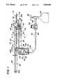
- FIG. 1is a side elevational view, partially in section, of the automatic biopsy device of the present invention
- FIG. 2is an enlarged sectional view of the device taken along the line 2--2 of FIG. 1;
- FIG. 3is an enlarged exploded isometric view of the stylet cassette, the stylet, and the cannula of the device of FIG. 1;
- FIG. 4is an enlarged top plan view, partially in section, of the distal end of the device of FIG. 1;
- FIG. 5is as an enlarged sectional view of the device taken along the line 5--5 of FIG. 1 and showing in phantom lines a stylet cassette which has been removed from the device;
- FIG. 6is a sectional view of the distal end of the device taken along the line 6--6 of FIG. 2;
- FIG. 7is a schematic diagram of the pneumatic system which powers the device of FIG. 1.
- the device 20is arranged to be held in the hand of a surgeon or other medical person to take plural tissue samples from a patient for study.
- the device 20basically comprises a gun-shaped housing 22, formed of any suitable material, e.g., aluminum, having a body portion 24 for releasable mounting therein a cassette 26.
- a cannula assembly 28At the distal end of the housing is a cannula assembly 28.
- This assemblybasically comprises an elongated tube having a distal end in the form of a cutting edge.
- the proximal end of the cannula assemblycomprises a block which serves to releasably mount the cannula assembly on the device 20.
- the deviceis arranged so that it can be readily manipulated by the surgeon so that the cannula 28A is inserted within the body of the patient, either percutaneously, or through a body lumen or orifice, e.g., transrectally, transuretherally, etc., to the site of the internal tissue to be sampled.
- the device's housing 22includes a handle 30 located below the body portion 24 so that it can be readily held in the surgeon's hand to orient the device, as desired, and to operate it.
- the cassette 26will be described in detail later. Suffice it for now to state that the cassette is a generally U-shaped structure having a hollow interior into which a tray 32 is located.
- the tray 32is arranged to hold a plurality of needle-like members or "stylets" 34A-34F.
- Each styletincludes a pointed distal end having an elongated notch or recess adjacent thereto.
- the recessis arranged to receive a portion of tissue to be excised so that when the cannula is slid thereover (as will be described later) the tissue within the recess is cut or sliced away from the remaining tissue of the patient's body and is held within the recess.
- the tray bearing the styletsis arranged to be moved to a position within the housing so that a stylet is aligned with the cannula 28A. Thereafter the device is operated to cause that stylet to be extended, e.g., propelled, almost instantaneously out of the free end of the cannula 28A into the tissue to be sampled to enable a portion of that tissue to enter the notch in the stylet's distal end.
- the cannulais extended, e.g., propelled, almost instantaneously over the extended stylet so that the portion of the tissue within the stylet's recess is excised, i.e., sheared off by the passing cannula.
- the deviceis then operated to retract both the stylet and the cannula from the tissue being sampled, with the stylet with the tissue sample therein being retracted into the cassette.
- device 20may be used to sequentially take tissue samples by the use of respective stylets, and to withdraw those stylets into the cassette, until all of the desired samples are taken. At that time the cassette may be removed from the device 20 and transported to a laboratory for analysis of the tissue samples. A new cassette having a tray of fresh stylets may then be inserted into the device and a new cannula mounted on the device to replace the used cannula. Since only the cannula and the stylets contact the patient, and since these components are replaced, the device 20 is now ready for reuse on another patient.
- the extension and retraction of the stylets 34A-34F and the cannula 28are accomplished in the disclosed embodiment by a pneumatic drive system 40.
- That systemis merely exemplary and is shown in the schematic diagram of FIG. 7.
- the system 40basically comprises first and second pneumatic cylinders 42 and 44 respectively.
- the cylindersare driven by a compressed gas, e.g., carbon dioxide.
- the first cylinder 42includes a piston 46 which is coupled to a catch 50 (to be described later) for selectively engaging the proximal end of each stylet 24A-24F to effect the extension and retraction of the engaged stylet.
- the second cylinder 44includes piston 48 which is coupled to a carrier 52 (to be described later).
- the carrier 52supports the cannula assembly 28 and particularly its mounting block thereon to effect the extension and retraction of the cannula with respect to the housing.
- the tray 32is arranged to be sequentially moved with respect to the housing when the cassette is mounted within the housing to bring selected ones of the stylets into alignment with the cannula 28 so that they can be extended therethrough by the operation of the cylinder 42, and then the cannula is automatically extended over the extended stylet by the operation of the cylinder 44.
- the movement of the piston 46 of the cylinder 42 in the distal direction to cause the extension of a selected stylet out of the cassette and through the cannula 28A to penetrate or pierce the tissue to be sampledis effected by providing the compressed gas into the proximal end 42A of the pneumatic cylinder housing 42 via an input line 52.
- the movement of the piston in the proximal direction to cause the retraction of the stylet back through the cannula 28 and into the cassette 26is effected by providing the compressed gas into the distal end 42B of the pneumatic cylinder 42 via another input line 54.
- a reversing valve 56 and associated componentsare provided within the housing.
- the operation of the reversing valve 56is controlled by a manually actuatable trigger or button 58 located on the device's handle 30.
- the triggeris coupled to the valve 56 and is arranged so that when it is depressed the valve 56 switches from the state shown in FIG. 7 to the state allowing the compressed gas (from a source to be described later) to enter into input line 52.
- This actionimmediately causes the piston 46 and the stylet coupled thereto to move in the distal direction to extend the distal end of the stylet and its associated recess out of the free end of the cannula and into the tissue of the patient.
- the movement of the piston 48 of the cylinder 44 in the proximal direction to extend the cannula over now extended stylet to excise the portion of the tissue within the stylet's grooveis effected by providing compressed gas into the proximal end 44A of the second pneumatic cylinder 44 via an input line 60.
- This extension of the cannula over the extended styletoccurs automatically virtually immediately after the stylet has been extended into the tissue to be sampled (as will be described later).
- the movement of the piston 48 in the proximal direction to cause the retraction of the cannula out of the tissue of the patientis effected by providing the compressed gas into the distal end 44B of the cylinder via another input line 62.
- a second reversing valve 64is provided in order to control which of the input lines 60 or 62 provides the compressed gas to the cylinder 44.
- the valve 64is mounted at the distal end of the device 20 and includes a plunger 66 which is arranged to be engaged by a pivotal lever arm 68.
- the lever armis mounted at the distal end of the housing adjacent the cannula-supporting carrier 52 and is arranged to be engaged by the catch 50 on the piston rod 46A when the piston rod of cylinder 42 is propelled outward, i.e. once the stylet has been extended into the tissue to be excised.
- This actioncauses the pivotally arm 68 to swing into engagement with the plunger 66, thereby depressing the plunger and causing the reversing valve 64 connected thereto to assume the state wherein the compressed gas is provided via line 60 into the proximal end 44A of the cylinder 44. Accordingly, the piston 48 is automatically immediately propelled in the proximal direction, thereby carrying the carriage 52 with the cannula assembly 28 mounted thereon outward over the extended stylet to excise the tissue within the stylet's groove.
- the compressed gasis permitted to flow through the reversing valve 56 into the line 54, whereupon the piston 46 of the cylinder 42 is propelled in the proximal direction, thereby retracting the stylet back into the housing.
- the catch 50 on the pistonreaches the location of the lever arm 68 it releases that arm, whereupon the plunger 66 is freed and the second reversing valve 64 immediately changes state so that the compressed carbon dioxide is provided via line 62 into the proximal end of the second cylinder 44. This action propels the piston 48 of that cylinder in the proximal direction, thereby retracting the carrier and the cannula mounted thereon.
- the cannulaWhen the pistons of both cylinders are fully retracted, that is they are in the position shown in FIG. 2 and 7, the cannula will have been withdrawn from the tissue site. Moreover, the stylet which has the tissue sample in its groove will now be completely retracted within a groove (to be described later) in the tray 32 within the cassette 26. The device 20 is now ready to take another tissue sample via the extension of the next stylet and followed by the extension of the cannula assembly 28 over that stylet.
- the compressed gas for the system 40is provided from any suitable source, e.g., a compressed CO 2 cylinder 80, via an adjustable valve 82.
- the outlet of the valve 82is connected to a metering device 84 via a line or conduit 86.
- the output of the metering device 84is provided via line or conduit 88 to the input of a T-coupling 90.
- a filter 92(FIG. 1) is preferably included in the conduit 88.
- the T-couplingincludes a pair of output lines 94 and 96, which are connected to the inputs of the reversing valves 56 and 64, respectively.
- the solid diagonal lines in the reversing valves 56 and 64represent the quiescent state of those valves, i.e., the state of the device when it is ready to take a tissue sample, prior to the depressing of the trigger 58.
- the pistons 46 and 48are located to the rear (proximally) in the pneumatic cylinders 42 and 44, respectively.
- the dotted diagonal lines in the reversing valvesrepresent the connections made when the trigger is depressed and the plunger 66 is pushed forward by the lever arm 68.
- Each of the reversing valvesincludes at least one gas release path which are designated by the solid vertical lines in those valves to allow the existing gas in the pneumatic cylinders 42 and 44 to be released therefrom so as not to oppose the movement of the pistons 46 and 48, respectively, either in the forward (distal) or the backward (proximal) direction. This is of considerable importance to ensure that the pistons move virtually instantaneously.
- each styletis an elongated needle or rod-like member having a distal end which is sharpened, i.e., cut at an angle, to provide a piercing point 100.
- An elongated recess or groove 102is provided in the stylet adjacent its piercing tip 100.
- the groove 102serves as the repository for the tissue to be excised.
- the proximal end of the styletincludes a block of 104.
- the block 104is arranged to be selectively received within a groove 106 in the catch 50. When the block is within that groove the movement of the piston rod 46A either proximally or distally causes the concomitant movement of the stylet therewith.
- the stylet and cannulacan be formed of any suitable material.
- the eachis formed of stainless steel.
- the cannula assembly 28basically comprises an elongated tubular member having a free distal end 110 cut at an angle to the longitudinal axis of the cannula to form a sharp cutting edge.
- the proximal end of the cannula assembly 28is in the form of the heretofore mentioned mounting block 108.
- the block 108is formed of any suitable material, e.g., plastic, and includes a flared inlet toward 112 at its proximal face and which communicates with the hollow interior of the tubular cannula 28A.
- Each corner of the block 108includes a recess 114 therein which is arranged to receive respective edges of upstanding walls 52A of the cannula carrier 52 (see FIG. 4) to hold the cannula in place on the carrier.
- a set screw 116is provided in one of the walls 52A of the carrier 52 to engage the block 108 to lock the cannula assembly 28 on the carrier 52.
- the carrier 52is mounted on a pair of rod-like guide rails 118 to enable the carrier to be slid along the rails, i.e., reciprocated, by the movement of the piston of cylinder 44.
- the guide rails 118are mounted within the housing via a bracket 120 and associated screws 122.
- the cannula 28Aextends out of the housing of via a slot 124 in the front end thereof when the cannula assembly is mounted on the carrier 52.
- the cassette 26includes a tray 32 therein.
- the tray 32includes plural grooves 130 disposed in a side-by-side array along the length of the tray i.e., from its distal end to its proximal end. Each groove 130 is arranged to receive a respective one of the stylets 34A-34F therein.
- the trayincludes a large planar tab or projection 132 extending outward from one side thereof. The projection 132 is arranged to be received within respective portions of the cassette to facilitate the positioning of the tray with respect to the cassette (as will be described later).
- the trayis arranged to be moved to sequentially align its grooves 130 with the cannula assembly 28 so that the stylet in each of the grooves can be selectively brought into alignment with the passageway through cannula 28A for passage therethrough into the tissue to be sampled.
- the cassette 26basically comprises a generally U-shaped member having a lower body portion or base 140 formed of any suitable material, e.g., aluminum, and a cover, e.g., clear plexiglass, 142 releasably secured thereover via plural threaded fasteners 144.
- the cassetteincludes an open side 146, i.e., the base 140 doesn't include an upstanding sidewall on that side so that the cover 142 is spaced over the base. This open side serves as the entrance for inserting a tray full of stylets into the cassette.
- tray 32is arranged to be inserted within the cassette 26 through the open end 146 of the cassette so that the tab 132 of the tray extends through a slot 148 in the sidewall of the base 140 and into a pair of guide slots 150.
- the guide slotsare provided on opposite sides of the slot 148 to receive the projection 132 of the tray 32 when the tray is located within the cassette 26.
- the tray 32is arranged to be moved laterally out of the cassette, that is through the open end 146, by pressing on the edge of the tab 132 once the cassette is in place within the device's housing. This aligns the groove 130 holding the stylet 34F, i.e., the first stylet to be ejected, with the catch 50 on the piston rod 46A and with the entrance port 112 on the cannula assembly 28.
- the deviceis now ready to take a tissue sample using stylet 34F as described earlier. Once that has been accomplished the device moves the tray into the cassette until that the next groove, i.e., the groove holding stylet 34E, is in axial alignment with the cannula 28 so that stylet 34E can be extended thereout to take a second tissue sample.
- Each operation of the device to take a sampleresults in the movement of the tray to a new position to bring the next stylet into alignment with the cannula for propulsion therethrough to take the next tissue sample.
- the means for moving the tray 32 to sequentially align the stylets with the cannula 28basically comprises a spring based pusher plate 152 (FIGS. 2 and 5).
- the plate 152is arranged to engage the edge 32A of the tray disposed opposite to the projection 132.
- the pusher plate 152is mounted on a pair of transversely extending rods 154 mounted in the housing.
- a pair of tension springs 156are mounted within the housing secured to the plate 152 to bias the plate into an engagement with the edge 32A of the tray to sequentially carry the tray deeper into the cassette 26 after each tissue sampling operation.
- a ratchet mechanismis provided to hold the tray against the bias of the springs 156 so that the next successive grooves 130 having a stylet therein will be aligned with the cannula 28 after the previously stylet has taken a tissue sample.
- the ratchet mechanismbasically comprises a lever arm 160 mounted on a pivot rod 162 in the housing.
- the lever 160includes a pawl-like projection or hook 164 arranged to sequentially engage respective detentes or grooves 166 in the proximal edge of the tray 32. Each groove has a respective detent or groove associated therewith.
- a biasing spring 168is connected to the lever 160 and to the housing to tend to pull the pawl-like hook 164 into the detente or groove 66 aligned therewith. This action prevents the tray from moving with respect to the cassette notwithstanding the bias force provided by the pusher plate 152.
- a set screw 170is provided in the lever arm 160 adjacent its connection to the spring 168. The set screw is arranged to abut an upstanding post 172 in the housing to enable the precise adjustment of the lever arm 160 to ensure that it operates properly with respect to the tray.
- the operation of the cylinder 42will propel the stylet 34F down its groove 130 so that the stylet's piercing tip 100 enters the flared entrance port 112 in the cannula.
- the continued motion of the piston in the distal directioncauses the stylet to pass through the cannula's passageway and out its sharp end 110 to pierce the tissue to be sampled.
- the cylinder 44is automatically operated to immediately slide the cannula over the extended stylet to excise that tissue sample.
- the cylinders 42 and 44are arranged to propel the stylet and cannula at speeds greater than the speed at which the body transmits pain impulses, e.g., at speeds in excess of 5-6 meters per second.
- the catch 50includes a spur 180 thereon. This spur 180 is arranged to momentarily engage a leaf spring 182 mounted on the pivot lever 160 to momentarily pivot the lever 160 in the clockwise direction as view in FIG.
- a pivotable, spring biased bar 184is mounted within the housing to overlay the groove 130 in the tray that is then aligned with the cannula's passageway to prevent the stylet located in that groove from jumping out of the groove when the stylet is propelled forward.
- the pivoting bar 184is biased by a tension spring 186 and is mounted on a bracket 188 located over the proximal end of the tray 32.
- the bar 184is pivotable about a screw 190 so that it can be pivoted out of the way of the catch 50 passing thereby when the device is in the state shown in FIG. 4, i.e., when the stylet is extended fully out of the cannula so that the catch 50 engages the pivot arm 68.
- the biasing spring 186returns the lever arm 184 to the position overlying the groove when the catch 50 has been retracted to the proximal position shown in FIG. 2.
- the spur 180 on the catch 50will monetarily engages the spring 182 to thereby release the pawl-like hook 164 from the associated groove or detente 166 and thereby enable the pusher bar to move the tray one groove further into the cassette to align the next stylet with the cannula.
- the cassette 26is arranged to be releasably secured within the device's housing by means of a pair of latch assemblies 202 and 204. These assemblies are best seen in FIG. 2.
- Each latch assemblyis of identical construction.
- the latch assembly 202is mounted on one side of the device's housing 24 immediately adjacent the handle 30, while the latch assembly 204 is mounted on the housing portion of 24 adjacent the cannula assembly 28.
- the latch assembly 202is arranged to releasable engage a flanged tab 206 screwed onto one end of the sidewall of the cassette body, while the latch assembly 204 is adapted to engage a similarly constructed tab 208 screwed on the sidewall at the other end of the cassette body.
- Each latch assemblybasically comprises a sliding catch 208, an actuating pin 210, a biasing spring 212, and a cover plate 214 having a slot 216 therein.
- the catch 208 of assembly 202includes a groove 218 adapted to receive the flanged portion of the tab 206 therein to hold the cassette in place.
- the catch 208 of assembly 204includes a similar groove to receive the flanged portion of tab 208.
- a cassette having fresh stylets thereinis inserted into the housing by operating the latches 202 and 204.
- the stylet bearing trayis then pushed partially out of the cassette by pressing on its projection 132 against the bias of the biasing plate so that the pawl-like hook 164 mates with the detent of the groove 130 in which the first stylet to be ejected, i.e., stylet 34F, is located.
- the surgeonthen manipulates the device 20 by its handle 30 so that the free end of the cannula 28A inserted in the patient's body is located at a position adjacent the tissue to be sampled. It should be pointed out at this juncture that when the device 20 is to be introduced through a lumen or other opening in the patient's body, e.g., transurethrally, transrectally, a tubular shield 10, (shown by the phantom lines in FIG. 1) is placed over the cannula 28A to protect the patient from its sharp end 110.
- a tubular shield 10shown by the phantom lines in FIG. 1
- the aiming of the tip of the cannula to the desired position and orientationis preferably effected by use of ultrasound or any other form of imaging.
- Some present medical procedurescall for multiple, e.g., six, biopsy samples of a patient.
- the device 20 of this inventionenables the surgeon to take such samples without having to withdraw the device from the patient's body or to reload it with stylets.
- the surgeoncan quickly and easily take up to six tissue samples by merely aiming instrument and pressing its trigger for each sample to be taken.
- the styletsare quite long, e.g., 170 mm, and are arranged to extend out of the cannula by a substantial distance, so that the tip 110 of the cannula need not be manually inserted in the organ to be tested, as has characterized the prior art.
- the tip of the cannulaneed not be manual pushed by the surgeon into the organ or tissue.
- the pneumatic cylinderwill provide such action at high speed thereby reducing pain or trauma.
- the local area of the body surfaceis first anesthetized and the skin and underlying tissue is pierced by manually pressing the cannula 28 so that its piercing tip 110 enters into the patient's body to a location adjacent the tissue/organ to be sampled.
- the devicemay then be operated as described earlier, i.e., depressing the trigger 58 in sequence to cause the stylets 34A to 34F to take tissue samples in sequence. This operation can accomplished virtually as fast as the trigger can be depressed, released, redepressed, re-released, and so on.
- the cassette 26may be removed from the device 20 by releasing latching members 202 and 204.
- the removed cassette, with its tray of tissue bearing stylets,can then be transported to the laboratory safely (shown by the phantom lines in FIG. 5) and without the danger of injury to personnel or to the tissue samples.
- the cassettecan be immersed in a fluid which prevent the samples from drying out prior to testing. If additional tissue samples are needed of the patient a new cassette can be inserted in the device while the device remains in place with the cannula extending into the patient's body.
- the cassette, its tray and the stylets held therein, and the cannula assemblyare preferably in the form of a replaceable, disposable kit arranged for use with the automatic biopsy device 20 described heretofore.
- the automatic biopsy device 20described heretofore.
- the embodiment shown hereinuses a pneumatic system, operated by compressed carbon dioxide, to drive the stylets and cannula forward and then in reverse.
- the inventionwill work just as well with other gases or with other types of powered drives, such as hydraulic or electric.
- the embodiment disclosed hereinshows a cassette tray with six stylets for the taking of six biopsies, cassettes with more or less stylets can be provided.
- the length of the styletsmay be selected to control the depth of penetration provided thereby. Thus, for some applications shorter stylets may be used and for other applications longer stylets may be used.
- an automatic biopsy device of this inventionenables a surgeon, using one hand, to take a plurality of biopsies in rapid sequence by successively depressing a trigger.
- the devicemay be powered by electric, pneumatic, hydraulic or other means.
- the cassette with the stylets 34A-34F having tissue samples 200 thereincan be removed by merely releasing the latches 202 and 204.
- the cassettecan then be taken to the laboratory for study and analysis, with the cassette's body protecting the samples and the personnel handling the samples.
- the device 20 of this inventiondoes not require the manual piercing of the tissue to take the specimen and assures that the biopsy is taken at the proper location, because the length of the stylets determine the penetration into the body and into the organ to be sampled. This is particularly advantageous because existing devices do not protect against under-insertion of the stylet, which results in a sampling of the wrong tissues, or over-insertion of the stylets which can cause damage to the organ.
Landscapes
- Health & Medical Sciences (AREA)
- Life Sciences & Earth Sciences (AREA)
- Medical Informatics (AREA)
- Engineering & Computer Science (AREA)
- Biomedical Technology (AREA)
- Heart & Thoracic Surgery (AREA)
- Pathology (AREA)
- Molecular Biology (AREA)
- Surgery (AREA)
- Animal Behavior & Ethology (AREA)
- General Health & Medical Sciences (AREA)
- Public Health (AREA)
- Veterinary Medicine (AREA)
- Surgical Instruments (AREA)
Abstract
Description
Claims (36)
Priority Applications (1)
| Application Number | Priority Date | Filing Date | Title |
|---|---|---|---|
| US07/951,611US5234000A (en) | 1992-09-25 | 1992-09-25 | Automatic biopsy device housing a plurality of stylets |
Applications Claiming Priority (1)
| Application Number | Priority Date | Filing Date | Title |
|---|---|---|---|
| US07/951,611US5234000A (en) | 1992-09-25 | 1992-09-25 | Automatic biopsy device housing a plurality of stylets |
Publications (1)
| Publication Number | Publication Date |
|---|---|
| US5234000Atrue US5234000A (en) | 1993-08-10 |
Family
ID=25491914
Family Applications (1)
| Application Number | Title | Priority Date | Filing Date |
|---|---|---|---|
| US07/951,611Expired - Fee RelatedUS5234000A (en) | 1992-09-25 | 1992-09-25 | Automatic biopsy device housing a plurality of stylets |
Country Status (1)
| Country | Link |
|---|---|
| US (1) | US5234000A (en) |
Cited By (101)
| Publication number | Priority date | Publication date | Assignee | Title |
|---|---|---|---|---|
| WO1995025465A3 (en)* | 1994-03-24 | 1996-02-15 | Biopsys Medical Inc | Automated biopsy apparatus |
| US5542432A (en)* | 1992-02-18 | 1996-08-06 | Symbiosis Corporation | Endoscopic multiple sample bioptome |
| US5564436A (en)* | 1995-09-21 | 1996-10-15 | Hakky; Said I. | Automatic rotating cassette multiple biopsy device |
| WO1996024289A3 (en)* | 1995-02-10 | 1996-10-31 | Biopsys Medical Inc | Methods and devices for automated biopsy and collection of soft tissue |
| WO1998033435A1 (en)* | 1997-01-30 | 1998-08-06 | Boston Scientific Corporation | Pneumatically actuated tissue sampling device |
| US5810744A (en)* | 1993-05-17 | 1998-09-22 | Boston Scientific Corporation | Instrument for collecting multiple biopsy specimens |
| US5871453A (en)* | 1994-02-08 | 1999-02-16 | Boston Scientific Corporation | Moveable sample tube multiple biopsy sampling device |
| WO1999034734A1 (en) | 1998-01-02 | 1999-07-15 | Biopsy Needle Limited Partnership | Biopsy instrument |
| US5944673A (en)* | 1998-05-14 | 1999-08-31 | Ethicon Endo-Surgery, Inc. | Biopsy instrument with multi-port needle |
| US5954670A (en)* | 1994-10-05 | 1999-09-21 | Baker; Gary H. | Mandrel-guided tandem multiple channel biopsy guide device and method of use |
| US5964716A (en)* | 1998-05-14 | 1999-10-12 | Ethicon Endo-Surgery, Inc. | Method of use for a multi-port biopsy instrument |
| US6017316A (en)* | 1997-06-18 | 2000-01-25 | Biopsys Medical | Vacuum control system and method for automated biopsy device |
| US6142957A (en)* | 1993-09-20 | 2000-11-07 | Boston Scientific Corporation | Multiple biopsy sampling device |
| US6193671B1 (en) | 1994-02-01 | 2001-02-27 | Symbiosis Corporation | Endoscopic multiple sample bioptome with enhanced biting action |
| US20020177837A1 (en)* | 2001-04-24 | 2002-11-28 | Barnitz James C. | Cassettes supporting intracranial perfusions |
| US6551255B2 (en)* | 2000-10-16 | 2003-04-22 | Sanarus Medical, Inc. | Device for biopsy of tumors |
| US20030195436A1 (en)* | 2000-10-16 | 2003-10-16 | Sanarus Medical Incorporated | Device for biopsy of tumors |
| US6665554B1 (en) | 1998-11-18 | 2003-12-16 | Steve T. Charles | Medical manipulator for use with an imaging device |
| US6673023B2 (en) | 2001-03-23 | 2004-01-06 | Stryker Puerto Rico Limited | Micro-invasive breast biopsy device |
| US6676669B2 (en) | 2001-01-16 | 2004-01-13 | Microdexterity Systems, Inc. | Surgical manipulator |
| US20040024385A1 (en)* | 1999-11-12 | 2004-02-05 | Microdexterity Systems, Inc. | Manipulator |
| US6712773B1 (en) | 2000-09-11 | 2004-03-30 | Tyco Healthcare Group Lp | Biopsy system |
| US6723106B1 (en) | 1998-11-23 | 2004-04-20 | Microdexterity Systems, Inc. | Surgical manipulator |
| US6860860B2 (en) | 2000-11-27 | 2005-03-01 | Tyco Healthcare Group, Lp | Tissue sampling and removal apparatus and method |
| US20050075581A1 (en)* | 2002-04-23 | 2005-04-07 | Jeffrey Schwindt | Pneumatic circuit |
| US20050165328A1 (en)* | 2002-03-19 | 2005-07-28 | Norbert Heske | Biopsy device and biopsy needle module that can be inserted into the biopsy device |
| US20050177211A1 (en)* | 2002-03-05 | 2005-08-11 | Baylis Medical Company Inc. | Electrosurgical device for treatment of tissue |
| US20050182394A1 (en)* | 2004-02-12 | 2005-08-18 | Spero Richard K. | Rotational core biopsy device with liquid cryogen adhesion probe |
| US20050203439A1 (en)* | 2002-03-19 | 2005-09-15 | Norbert Heske | Vacuum biopsy device |
| US20050209530A1 (en)* | 2001-03-23 | 2005-09-22 | Stryker Puerto Rico Limited | Micro-invasive tissue removal device |
| US20060149147A1 (en)* | 2003-06-18 | 2006-07-06 | Yanof Jeffrey H | Remotely held needle guide for ct fluoroscopy |
| US20060206133A1 (en)* | 2005-03-11 | 2006-09-14 | Baylis Medical Company Inc. | Method for removing material from a patient's body |
| US20070032743A1 (en)* | 2005-08-05 | 2007-02-08 | Hibner John A | Vacuum Syringe Assisted Biopsy Device |
| US20070032742A1 (en)* | 2005-08-05 | 2007-02-08 | Monson Gavin M | Biopsy Device with Vacuum Assisted Bleeding Control |
| US20070055173A1 (en)* | 2005-08-23 | 2007-03-08 | Sanarus Medical, Inc. | Rotational core biopsy device with liquid cryogen adhesion probe |
| US20070239067A1 (en)* | 2005-08-05 | 2007-10-11 | Hibner John A | Tissue Sample Revolver Drum Biopsy Device |
| US20070250078A1 (en)* | 2001-01-16 | 2007-10-25 | Microdexterity Systems, Inc. | Surgical manipulator |
| US20070255172A1 (en)* | 2001-03-23 | 2007-11-01 | Stryker Puerto Rico Limited | Micro-invasive nucleotomy device and method |
| US20080004545A1 (en)* | 2005-08-05 | 2008-01-03 | Garrison William A | Trigger Fired Radial Plate Specimen Retrieval Biopsy Instrument |
| US20080065062A1 (en)* | 2002-03-05 | 2008-03-13 | Baylis Medical Company Inc. | Electrosurgical tissue treatment method |
| US20080071193A1 (en)* | 2004-07-09 | 2008-03-20 | Claus Reuber | Length Detection System for Biopsy Device |
| WO2007112751A3 (en)* | 2006-03-31 | 2008-05-08 | Sonion Roskilde As | Tissue sample collection system with visual sample inspection |
| US20080132804A1 (en)* | 2000-10-13 | 2008-06-05 | Stephens Randy R | Remote Thumbwheel For Surgical Biopsy Device |
| US20080195066A1 (en)* | 2006-12-13 | 2008-08-14 | Speeg Trevor W V | Revolving Tissue Sample Holder For Biopsy Device |
| US20080306406A1 (en)* | 2005-08-10 | 2008-12-11 | C.R. Bard Inc. | Single-Insertion, Multiple Sampling Biopsy Device With Linear Drive |
| US20080319341A1 (en)* | 2005-08-10 | 2008-12-25 | C.R. Bard Inc. | Single-Insertion, Multiple Sample Biopsy Device with Integrated Markers |
| US20090088664A1 (en)* | 2007-10-01 | 2009-04-02 | Miller Michael E | Surgical device and method for using same |
| US20090131820A1 (en)* | 2007-11-20 | 2009-05-21 | Speeg Trevor W V | Icon-Based User Interface On Biopsy System Control Module |
| US20090131823A1 (en)* | 2007-11-20 | 2009-05-21 | Andreyko Michael J | Biopsy Device With Illuminated Tissue Holder |
| US20090131817A1 (en)* | 2007-11-20 | 2009-05-21 | Speeg Trevor W V | Deployment device interface for biopsy device |
| US20090131821A1 (en)* | 2007-11-20 | 2009-05-21 | Speeg Trevor W V | Graphical User Interface For Biopsy System Control Module |
| US20090227893A1 (en)* | 2005-08-10 | 2009-09-10 | C.R. Bard Inc. | Single-insertion, multiple sampling biopsy device usable with various transport systems and integrated markers |
| US20100030108A1 (en)* | 2006-10-24 | 2010-02-04 | C.R. Bard, Inc. | Large sample low aspect ratio biopsy needle |
| US20100106053A1 (en)* | 2006-10-06 | 2010-04-29 | Videbaek Karsten | Tissue handling system with reduced operator exposure |
| US20100113971A1 (en)* | 2005-08-05 | 2010-05-06 | Ethicon Endo-Surgery, Inc. | Biopsy Device with Translating Valve Mechanism |
| US20100160824A1 (en)* | 2008-12-18 | 2010-06-24 | Parihar Shailendra K | Biopsy Device with Discrete Tissue Chambers |
| US20100228146A1 (en)* | 2004-09-29 | 2010-09-09 | Hibner John A | Biopsy Device With Integral vacuum Assist And Tissue Sample And Fluid Capturing Canister |
| US20100234760A1 (en)* | 2006-08-21 | 2010-09-16 | Dan Almazan | Self-contained Handheld Biopsy Needle |
| US7806835B2 (en) | 2007-11-20 | 2010-10-05 | Devicor Medical Products, Inc. | Biopsy device with sharps reduction feature |
| US20100275718A1 (en)* | 2009-04-29 | 2010-11-04 | Microdexterity Systems, Inc. | Manipulator |
| US20110021946A1 (en)* | 2003-03-29 | 2011-01-27 | C.R. Bard, Inc. | Biopsy needle system having a pressure generating unit |
| US7896817B2 (en) | 2005-08-05 | 2011-03-01 | Devicor Medical Products, Inc. | Biopsy device with manually rotated sample barrel |
| US20110054350A1 (en)* | 2009-09-01 | 2011-03-03 | Videbaek Karsten | Biopsy apparatus having a tissue sample retrieval mechanism |
| US20110077551A1 (en)* | 2009-09-25 | 2011-03-31 | Videbaek Karsten | Charging station for battery powered biopsy apparatus |
| US20110087131A1 (en)* | 2009-10-12 | 2011-04-14 | Videbaek Karsten | Biopsy probe assembly having a mechanism to prevent misalignment of components prior to installation |
| US20110088500A1 (en)* | 2007-02-23 | 2011-04-21 | Microdexterity Systems, Inc. | Manipulator |
| US20110105945A1 (en)* | 2009-10-29 | 2011-05-05 | Videbaek Karsten | Biopsy driver assembly having a control circuit for conserving battery power |
| US20110105946A1 (en)* | 2009-10-31 | 2011-05-05 | Sorensen Peter L | Biopsy system with infrared communications |
| US7938786B2 (en) | 2006-12-13 | 2011-05-10 | Devicor Medical Products, Inc. | Vacuum timing algorithm for biopsy device |
| US7981049B2 (en) | 2006-12-13 | 2011-07-19 | Devicor Medical Products, Inc. | Engagement interface for biopsy system vacuum module |
| US20110208085A1 (en)* | 2005-01-31 | 2011-08-25 | C.R. Bard, Inc. | Quick cycle biopsy system |
| USD647613S1 (en) | 2010-12-30 | 2011-10-25 | Kimberly-Clark, Inc. | Ergonomic handle for medical device |
| US8052616B2 (en) | 2007-11-20 | 2011-11-08 | Devicor Medical Products, Inc. | Biopsy device with fine pitch drive train |
| US8454532B2 (en) | 2007-12-27 | 2013-06-04 | Devicor Medical Products, Inc. | Clutch and valving system for tetherless biopsy device |
| US8480595B2 (en) | 2006-12-13 | 2013-07-09 | Devicor Medical Products, Inc. | Biopsy device with motorized needle cocking |
| US8597205B2 (en) | 2007-12-20 | 2013-12-03 | C. R. Bard, Inc. | Biopsy device |
| US8690793B2 (en) | 2009-03-16 | 2014-04-08 | C. R. Bard, Inc. | Biopsy device having rotational cutting |
| US8708929B2 (en) | 2009-04-15 | 2014-04-29 | Bard Peripheral Vascular, Inc. | Biopsy apparatus having integrated fluid management |
| US8808200B2 (en) | 2007-10-01 | 2014-08-19 | Suros Surgical Systems, Inc. | Surgical device and method of using same |
| US8845548B2 (en) | 2009-06-12 | 2014-09-30 | Devicor Medical Products, Inc. | Cutter drive assembly for biopsy device |
| US8932233B2 (en) | 2004-05-21 | 2015-01-13 | Devicor Medical Products, Inc. | MRI biopsy device |
| US9039634B2 (en) | 2007-11-20 | 2015-05-26 | Devicor Medical Products, Inc. | Biopsy device tissue sample holder rotation control |
| US9095326B2 (en) | 2006-12-13 | 2015-08-04 | Devicor Medical Products, Inc. | Biopsy system with vacuum control module |
| US9173641B2 (en) | 2009-08-12 | 2015-11-03 | C. R. Bard, Inc. | Biopsy apparatus having integrated thumbwheel mechanism for manual rotation of biopsy cannula |
| USRE46135E1 (en) | 2005-08-05 | 2016-09-06 | Devicor Medical Products, Inc. | Vacuum syringe assisted biopsy device |
| US9474573B2 (en) | 2002-03-05 | 2016-10-25 | Avent, Inc. | Electrosurgical tissue treatment device |
| US9638770B2 (en) | 2004-05-21 | 2017-05-02 | Devicor Medical Products, Inc. | MRI biopsy apparatus incorporating an imageable penetrating portion |
| US9795365B2 (en) | 2004-05-21 | 2017-10-24 | Devicor Medical Products, Inc. | MRI biopsy apparatus incorporating a sleeve and multi-function obturator |
| US9968338B2 (en) | 2012-11-21 | 2018-05-15 | C. R. Bard, Inc. | Core needle biopsy device |
| US10285673B2 (en) | 2013-03-20 | 2019-05-14 | Bard Peripheral Vascular, Inc. | Biopsy device |
| US10456120B2 (en) | 2013-11-05 | 2019-10-29 | C. R. Bard, Inc. | Biopsy device having integrated vacuum |
| US10463350B2 (en) | 2015-05-01 | 2019-11-05 | C. R. Bard, Inc. | Biopsy device |
| US10595831B2 (en) | 2012-05-30 | 2020-03-24 | Devicor Medical Products, Inc. | Control for biopsy device |
| US11116483B2 (en) | 2017-05-19 | 2021-09-14 | Merit Medical Systems, Inc. | Rotating biopsy needle |
| US11179141B2 (en) | 2006-12-13 | 2021-11-23 | Devicor Medical Products, Inc. | Biopsy system |
| US20220047251A1 (en)* | 2018-12-14 | 2022-02-17 | Multi4 Ab | A tissue specimen collector for use in biopsy |
| US11793498B2 (en) | 2017-05-19 | 2023-10-24 | Merit Medical Systems, Inc. | Biopsy needle devices and methods of use |
| CN117064456A (en)* | 2023-10-17 | 2023-11-17 | 江西省水产科学研究所(江西省鄱阳湖渔业研究中心、江西省渔业资源生态环境监测中心) | Automatic sampling device for crucian immune tissues |
| US11844500B2 (en) | 2017-05-19 | 2023-12-19 | Merit Medical Systems, Inc. | Semi-automatic biopsy needle device and methods of use |
| US12150627B2 (en) | 2019-12-11 | 2024-11-26 | Merit Medical Systems, Inc. | Bone biopsy device and related methods |
| US12295556B2 (en) | 2019-09-27 | 2025-05-13 | Merit Medical Systems, Inc. | Rotation biopsy system and handle |
Citations (10)
| Publication number | Priority date | Publication date | Assignee | Title |
|---|---|---|---|---|
| US3949747A (en)* | 1974-10-03 | 1976-04-13 | Hevesy William K | Biopsy set |
| US4476864A (en)* | 1982-09-29 | 1984-10-16 | Jirayr Tezel | Combined multiple punch and single punch hair transplant cutting device |
| EP0269164A1 (en)* | 1986-11-09 | 1988-06-01 | Staalkat B.V. | Tattooing device |
| US4766907A (en)* | 1986-10-15 | 1988-08-30 | Groot William J De | Apparatus and method for performing a biopsy and a device for manipulating same |
| US4907599A (en)* | 1988-02-01 | 1990-03-13 | Hart Enterprises, Inc. | Soft tissue core biopsy instrument |
| US4946035A (en)* | 1988-04-11 | 1990-08-07 | Ivy Laboratories, Inc. | Implanter applicator |
| US5012818A (en)* | 1989-05-04 | 1991-05-07 | Joishy Suresh K | Two in one bone marrow surgical needle |
| US5133359A (en)* | 1990-11-14 | 1992-07-28 | Du-Kedem Technologies Ltd. | Hard tissue biopsy instrument with rotary drive |
| US5143084A (en)* | 1990-05-24 | 1992-09-01 | Spacelabs, Inc. | Disposable cartridge for sampling and analyzing body fluids |
| US5156160A (en)* | 1990-06-22 | 1992-10-20 | Bennett Lavon L | Adjustable biopsy device capable of controlling tissue sample size collected thereby |
- 1992
- 1992-09-25USUS07/951,611patent/US5234000A/ennot_activeExpired - Fee Related
Patent Citations (10)
| Publication number | Priority date | Publication date | Assignee | Title |
|---|---|---|---|---|
| US3949747A (en)* | 1974-10-03 | 1976-04-13 | Hevesy William K | Biopsy set |
| US4476864A (en)* | 1982-09-29 | 1984-10-16 | Jirayr Tezel | Combined multiple punch and single punch hair transplant cutting device |
| US4766907A (en)* | 1986-10-15 | 1988-08-30 | Groot William J De | Apparatus and method for performing a biopsy and a device for manipulating same |
| EP0269164A1 (en)* | 1986-11-09 | 1988-06-01 | Staalkat B.V. | Tattooing device |
| US4907599A (en)* | 1988-02-01 | 1990-03-13 | Hart Enterprises, Inc. | Soft tissue core biopsy instrument |
| US4946035A (en)* | 1988-04-11 | 1990-08-07 | Ivy Laboratories, Inc. | Implanter applicator |
| US5012818A (en)* | 1989-05-04 | 1991-05-07 | Joishy Suresh K | Two in one bone marrow surgical needle |
| US5143084A (en)* | 1990-05-24 | 1992-09-01 | Spacelabs, Inc. | Disposable cartridge for sampling and analyzing body fluids |
| US5156160A (en)* | 1990-06-22 | 1992-10-20 | Bennett Lavon L | Adjustable biopsy device capable of controlling tissue sample size collected thereby |
| US5133359A (en)* | 1990-11-14 | 1992-07-28 | Du-Kedem Technologies Ltd. | Hard tissue biopsy instrument with rotary drive |
Non-Patent Citations (2)
| Title |
|---|
| Quinton Instruments "Operator Manual: Model 7 mm Hydraulic Biopsy Instrument" pp. 1-15, Seattle, Washington, Jun. 1976. |
| Quinton Instruments Operator Manual: Model 7 mm Hydraulic Biopsy Instrument pp. 1 15, Seattle, Washington, Jun. 1976.* |
Cited By (284)
| Publication number | Priority date | Publication date | Assignee | Title |
|---|---|---|---|---|
| US5542432A (en)* | 1992-02-18 | 1996-08-06 | Symbiosis Corporation | Endoscopic multiple sample bioptome |
| US5951488A (en)* | 1992-02-18 | 1999-09-14 | Symbiosis Corporation | Endoscopic multiple sample bioptome |
| US5810744A (en)* | 1993-05-17 | 1998-09-22 | Boston Scientific Corporation | Instrument for collecting multiple biopsy specimens |
| US6142957A (en)* | 1993-09-20 | 2000-11-07 | Boston Scientific Corporation | Multiple biopsy sampling device |
| US6561988B1 (en) | 1994-02-01 | 2003-05-13 | Symbiosis Corporation | Endoscopic multiple sample bioptome with enhanced biting action |
| US6193671B1 (en) | 1994-02-01 | 2001-02-27 | Symbiosis Corporation | Endoscopic multiple sample bioptome with enhanced biting action |
| US6053877A (en)* | 1994-02-08 | 2000-04-25 | Boston Scientific Corporation | Movable sample tube multiple biopsy sampling device |
| US5871453A (en)* | 1994-02-08 | 1999-02-16 | Boston Scientific Corporation | Moveable sample tube multiple biopsy sampling device |
| US8591435B2 (en)* | 1994-03-24 | 2013-11-26 | Devicor Medical Products, Inc. | Methods and devices for biopsy and collection of soft tissue |
| US5980469A (en)* | 1994-03-24 | 1999-11-09 | Ethicon Endo-Surgery, Inc. | Method and apparatus for automated biopsy and collection of soft tissue |
| US5775333A (en)* | 1994-03-24 | 1998-07-07 | Ethicon Endo-Surgery, Inc. | Apparatus for automated biopsy and collection of soft tissue |
| US7981050B2 (en) | 1994-03-24 | 2011-07-19 | Devicor Medical Products, Inc. | Methods and devices for automated biopsy and collection of soft tissue |
| US5928164A (en)* | 1994-03-24 | 1999-07-27 | Ethicon Endo-Surgery, Inc. | Apparatus for automated biopsy and collection of soft tissue |
| US7918803B2 (en) | 1994-03-24 | 2011-04-05 | Devicor Medical Products, Inc. | Methods and devices for automated biopsy and collection of soft tissue |
| US5649547A (en)* | 1994-03-24 | 1997-07-22 | Biopsys Medical, Inc. | Methods and devices for automated biopsy and collection of soft tissue |
| US20070156064A1 (en)* | 1994-03-24 | 2007-07-05 | Ritchart Mark A | Methods and Devices for Automated Biopsy and Collection of Soft Tissue |
| US7794411B2 (en) | 1994-03-24 | 2010-09-14 | Devicor Medical Products, Inc. | Methods and devices for automated biopsy and collection of soft tissue |
| US5526822A (en)* | 1994-03-24 | 1996-06-18 | Biopsys Medical, Inc. | Method and apparatus for automated biopsy and collection of soft tissue |
| US20040019299A1 (en)* | 1994-03-24 | 2004-01-29 | Ritchart Mark A. | Methods and devices for automated biopsy and collection of soft tissue |
| US20060167377A1 (en)* | 1994-03-24 | 2006-07-27 | Ritchart Mark A | Methods and devices for automated biopsy and collection of soft tissue |
| US20110160611A1 (en)* | 1994-03-24 | 2011-06-30 | Devicor Medical Products, Inc. | Methods and devices for biopsy and collection of soft tissue |
| EP1834590A3 (en)* | 1994-03-24 | 2007-11-28 | Ethicon Endo-Surgery, Inc. | Apparatus for automated biopsy and collection of soft tissue |
| US7226424B2 (en) | 1994-03-24 | 2007-06-05 | Ethicon Endo-Surgery, Inc. | Methods and devices for automated biopsy and collection of soft tissue |
| WO1995025465A3 (en)* | 1994-03-24 | 1996-02-15 | Biopsys Medical Inc | Automated biopsy apparatus |
| US20100063415A1 (en)* | 1994-03-24 | 2010-03-11 | Ritchart Mark A | Methods and devices for automated biopsy and collection of soft tissue |
| US6428486B2 (en) | 1994-03-24 | 2002-08-06 | Ethicon Endo-Surgery, Inc. | Methods and devices for automated biopsy and collection of soft tissue |
| US8808199B2 (en) | 1994-03-24 | 2014-08-19 | Devicor Medical Products, Inc. | Methods and devices for biopsy and collection of soft tissue |
| US20080154151A1 (en)* | 1994-03-24 | 2008-06-26 | Ritchart Mark A | Methods and Devices for Automated Biopsy and Collection of Soft Tissue |
| US5954670A (en)* | 1994-10-05 | 1999-09-21 | Baker; Gary H. | Mandrel-guided tandem multiple channel biopsy guide device and method of use |
| US8790276B2 (en) | 1995-02-10 | 2014-07-29 | Devicor Medical Products, Inc. | Methods and devices for biopsy and collection of soft tissue |
| WO1996024289A3 (en)* | 1995-02-10 | 1996-10-31 | Biopsys Medical Inc | Methods and devices for automated biopsy and collection of soft tissue |
| US5564436A (en)* | 1995-09-21 | 1996-10-15 | Hakky; Said I. | Automatic rotating cassette multiple biopsy device |
| WO1997010752A1 (en)* | 1995-09-21 | 1997-03-27 | Hakky Said I | Automatic biopsy device |
| US6273861B1 (en)* | 1997-01-30 | 2001-08-14 | Scimed Life Systems, Inc. | Pneumatically actuated tissue sampling device |
| WO1998033435A1 (en)* | 1997-01-30 | 1998-08-06 | Boston Scientific Corporation | Pneumatically actuated tissue sampling device |
| US6017316A (en)* | 1997-06-18 | 2000-01-25 | Biopsys Medical | Vacuum control system and method for automated biopsy device |
| US6315737B1 (en) | 1998-01-02 | 2001-11-13 | Biopsy Needle Limited Partnership | Biopsy needle for a biopsy instrument |
| US6022324A (en)* | 1998-01-02 | 2000-02-08 | Skinner; Bruce A. J. | Biopsy instrument |
| WO1999034734A1 (en) | 1998-01-02 | 1999-07-15 | Biopsy Needle Limited Partnership | Biopsy instrument |
| US5964716A (en)* | 1998-05-14 | 1999-10-12 | Ethicon Endo-Surgery, Inc. | Method of use for a multi-port biopsy instrument |
| US5944673A (en)* | 1998-05-14 | 1999-08-31 | Ethicon Endo-Surgery, Inc. | Biopsy instrument with multi-port needle |
| US6665554B1 (en) | 1998-11-18 | 2003-12-16 | Steve T. Charles | Medical manipulator for use with an imaging device |
| US6723106B1 (en) | 1998-11-23 | 2004-04-20 | Microdexterity Systems, Inc. | Surgical manipulator |
| US6702805B1 (en) | 1999-11-12 | 2004-03-09 | Microdexterity Systems, Inc. | Manipulator |
| US20040024385A1 (en)* | 1999-11-12 | 2004-02-05 | Microdexterity Systems, Inc. | Manipulator |
| US6712773B1 (en) | 2000-09-11 | 2004-03-30 | Tyco Healthcare Group Lp | Biopsy system |
| US7189207B2 (en) | 2000-09-11 | 2007-03-13 | Tyco Healthcare Group Lp | Biopsy system having a single use loading unit operable with a trocar driver, a knife driver and firing module |
| US8128577B2 (en) | 2000-09-11 | 2012-03-06 | Tyco Healthcare Group Lp | Biopsy system |
| US7648466B2 (en) | 2000-10-13 | 2010-01-19 | Ethicon Endo-Surgery, Inc. | Manually rotatable piercer |
| US20080132804A1 (en)* | 2000-10-13 | 2008-06-05 | Stephens Randy R | Remote Thumbwheel For Surgical Biopsy Device |
| US7311672B2 (en) | 2000-10-16 | 2007-12-25 | Sanarus Medical, Inc. | Device for biopsy of tumors |
| US6551255B2 (en)* | 2000-10-16 | 2003-04-22 | Sanarus Medical, Inc. | Device for biopsy of tumors |
| US20080103411A1 (en)* | 2000-10-16 | 2008-05-01 | Sanarus Medical Inc. | Device for Biopsy of Tumors |
| US20030195436A1 (en)* | 2000-10-16 | 2003-10-16 | Sanarus Medical Incorporated | Device for biopsy of tumors |
| US6860860B2 (en) | 2000-11-27 | 2005-03-01 | Tyco Healthcare Group, Lp | Tissue sampling and removal apparatus and method |
| US7513877B2 (en) | 2000-11-27 | 2009-04-07 | Tyco Healthcare Group Lp | Tissue sampling and removal apparatus and method |
| US7625383B2 (en) | 2001-01-16 | 2009-12-01 | Microdexterity Systems, Inc. | Surgical manipulator |
| US20040162564A1 (en)* | 2001-01-16 | 2004-08-19 | Microdexterity Systems, Inc. | Surgical manipulator |
| US20070250078A1 (en)* | 2001-01-16 | 2007-10-25 | Microdexterity Systems, Inc. | Surgical manipulator |
| US7892243B2 (en) | 2001-01-16 | 2011-02-22 | Microdexterity Systems, Inc. | Surgical manipulator |
| US6676669B2 (en) | 2001-01-16 | 2004-01-13 | Microdexterity Systems, Inc. | Surgical manipulator |
| US20040059254A1 (en)* | 2001-03-23 | 2004-03-25 | Stryker Puerto Rico Limited | Micro-invasive breast biopsy device |
| US7591790B2 (en) | 2001-03-23 | 2009-09-22 | Stryker Puerto Rico Limited | Micro-invasive device |
| US20070255172A1 (en)* | 2001-03-23 | 2007-11-01 | Stryker Puerto Rico Limited | Micro-invasive nucleotomy device and method |
| US6673023B2 (en) | 2001-03-23 | 2004-01-06 | Stryker Puerto Rico Limited | Micro-invasive breast biopsy device |
| US20050209530A1 (en)* | 2001-03-23 | 2005-09-22 | Stryker Puerto Rico Limited | Micro-invasive tissue removal device |
| US20020177837A1 (en)* | 2001-04-24 | 2002-11-28 | Barnitz James C. | Cassettes supporting intracranial perfusions |
| WO2002085430A3 (en)* | 2001-04-24 | 2003-02-20 | Neuron Therapeutics Inc | Cassettes supporting intracranial perfusions |
| US9474573B2 (en) | 2002-03-05 | 2016-10-25 | Avent, Inc. | Electrosurgical tissue treatment device |
| US20080065062A1 (en)* | 2002-03-05 | 2008-03-13 | Baylis Medical Company Inc. | Electrosurgical tissue treatment method |
| US8518036B2 (en) | 2002-03-05 | 2013-08-27 | Kimberly-Clark Inc. | Electrosurgical tissue treatment method |
| US10610297B2 (en) | 2002-03-05 | 2020-04-07 | Avent, Inc. | Electrosurgical tissue treatment device |
| US8043287B2 (en) | 2002-03-05 | 2011-10-25 | Kimberly-Clark Inc. | Method of treating biological tissue |
| US8740897B2 (en) | 2002-03-05 | 2014-06-03 | Kimberly-Clark, Inc. | Electrosurgical tissue treatment method and device |
| US8882755B2 (en) | 2002-03-05 | 2014-11-11 | Kimberly-Clark Inc. | Electrosurgical device for treatment of tissue |
| US20050177211A1 (en)* | 2002-03-05 | 2005-08-11 | Baylis Medical Company Inc. | Electrosurgical device for treatment of tissue |
| US10335128B2 (en) | 2002-03-19 | 2019-07-02 | C. R. Bard, Inc. | Biopsy device and insertable biopsy needle module |
| US8002713B2 (en) | 2002-03-19 | 2011-08-23 | C. R. Bard, Inc. | Biopsy device and insertable biopsy needle module |
| US8109885B2 (en) | 2002-03-19 | 2012-02-07 | C. R. Bard, Inc. | Biopsy device for removing tissue specimens using a vacuum |
| US8951209B2 (en) | 2002-03-19 | 2015-02-10 | C. R. Bard, Inc. | Biopsy device and insertable biopsy needle module |
| US20050165328A1 (en)* | 2002-03-19 | 2005-07-28 | Norbert Heske | Biopsy device and biopsy needle module that can be inserted into the biopsy device |
| US9072502B2 (en) | 2002-03-19 | 2015-07-07 | C. R. Bard, Inc. | Disposable biopsy unit |
| US20050203439A1 (en)* | 2002-03-19 | 2005-09-15 | Norbert Heske | Vacuum biopsy device |
| US10271827B2 (en) | 2002-03-19 | 2019-04-30 | C. R. Bard, Inc. | Disposable biopsy unit |
| US8016772B2 (en) | 2002-03-19 | 2011-09-13 | C. R. Bard, Inc. | Biopsy device for removing tissue specimens using a vacuum |
| US9421002B2 (en) | 2002-03-19 | 2016-08-23 | C. R. Bard, Inc. | Disposable biopsy unit |
| US9439631B2 (en) | 2002-03-19 | 2016-09-13 | C. R. Bard, Inc. | Biopsy device and insertable biopsy needle module |
| US11382608B2 (en) | 2002-03-19 | 2022-07-12 | C. R. Bard, Inc. | Disposable biopsy unit |
| US8172773B2 (en) | 2002-03-19 | 2012-05-08 | C. R. Bard, Inc. | Biopsy device and biopsy needle module that can be inserted into the biopsy device |
| US8052614B2 (en) | 2002-03-19 | 2011-11-08 | C. R. Bard, Inc. | Biopsy device having a vacuum pump |
| US20050075581A1 (en)* | 2002-04-23 | 2005-04-07 | Jeffrey Schwindt | Pneumatic circuit |
| US8728004B2 (en) | 2003-03-29 | 2014-05-20 | C.R. Bard, Inc. | Biopsy needle system having a pressure generating unit |
| US8162851B2 (en) | 2003-03-29 | 2012-04-24 | C. R. Bard, Inc. | Biopsy needle system having a pressure generating unit |
| US20110021946A1 (en)* | 2003-03-29 | 2011-01-27 | C.R. Bard, Inc. | Biopsy needle system having a pressure generating unit |
| US20060149147A1 (en)* | 2003-06-18 | 2006-07-06 | Yanof Jeffrey H | Remotely held needle guide for ct fluoroscopy |
| US9259195B2 (en)* | 2003-06-18 | 2016-02-16 | Koninklijke Philips N.V. | Remotely held needle guide for CT fluoroscopy |
| US20100049087A1 (en)* | 2004-02-12 | 2010-02-25 | Sanarus Technologies, Llc | Rotational Core Biopsy Device with Liquid Cryogen Adhesion Probe |
| US20080281225A1 (en)* | 2004-02-12 | 2008-11-13 | Spero Richard K | Rotational Core Biopsy Device With Liquid Cryogen Adhesion Probe |
| US7611475B2 (en) | 2004-02-12 | 2009-11-03 | Sanarus Technologies, Llc | Rotational core biopsy device with liquid cryogen adhesion probe |
| US7402140B2 (en) | 2004-02-12 | 2008-07-22 | Sanarus Medical, Inc. | Rotational core biopsy device with liquid cryogen adhesion probe |
| US8231545B2 (en) | 2004-02-12 | 2012-07-31 | Scion Medical Technologies, Llc | Rotational core biopsy device with liquid cryogen adhesion probe |
| US20050182394A1 (en)* | 2004-02-12 | 2005-08-18 | Spero Richard K. | Rotational core biopsy device with liquid cryogen adhesion probe |
| US9504453B2 (en) | 2004-05-21 | 2016-11-29 | Devicor Medical Products, Inc. | MRI biopsy device |
| US9392999B2 (en) | 2004-05-21 | 2016-07-19 | Devicor Medical Products, Inc. | MRI biopsy device |
| US8932233B2 (en) | 2004-05-21 | 2015-01-13 | Devicor Medical Products, Inc. | MRI biopsy device |
| US9795365B2 (en) | 2004-05-21 | 2017-10-24 | Devicor Medical Products, Inc. | MRI biopsy apparatus incorporating a sleeve and multi-function obturator |
| US9638770B2 (en) | 2004-05-21 | 2017-05-02 | Devicor Medical Products, Inc. | MRI biopsy apparatus incorporating an imageable penetrating portion |
| US20080071193A1 (en)* | 2004-07-09 | 2008-03-20 | Claus Reuber | Length Detection System for Biopsy Device |
| US20100210966A1 (en)* | 2004-07-09 | 2010-08-19 | Bard Peripheral Vascular, Inc. | Firing System For Biopsy Device |
| US8926527B2 (en) | 2004-07-09 | 2015-01-06 | Bard Peripheral Vascular, Inc. | Tissue sample flushing system for biopsy device |
| US20080183099A1 (en)* | 2004-07-09 | 2008-07-31 | Martin Bondo Jorgensen | Tissue Sample Flushing System for Biopsy Device |
| US8157744B2 (en) | 2004-07-09 | 2012-04-17 | Bard Peripheral Vascular, Inc. | Tissue sample flushing system for biopsy device |
| US8992440B2 (en) | 2004-07-09 | 2015-03-31 | Bard Peripheral Vascular, Inc. | Length detection system for biopsy device |
| US8052615B2 (en) | 2004-07-09 | 2011-11-08 | Bard Peripheral Vascular, Inc. | Length detection system for biopsy device |
| US8864680B2 (en) | 2004-07-09 | 2014-10-21 | Bard Peripheral Vascular, Inc. | Transport system for biopsy device |
| US9872672B2 (en) | 2004-07-09 | 2018-01-23 | Bard Peripheral Vascular, Inc. | Length detection system for biopsy device |
| US9456809B2 (en) | 2004-07-09 | 2016-10-04 | Bard Peripheral Vascular, Inc. | Tissue sample flushing system for biopsy device |
| US10166011B2 (en) | 2004-07-09 | 2019-01-01 | Bard Peripheral Vascular, Inc. | Transport system for biopsy device |
| US8366636B2 (en) | 2004-07-09 | 2013-02-05 | Bard Peripheral Vascular, Inc. | Firing system for biopsy device |
| US9345458B2 (en) | 2004-07-09 | 2016-05-24 | Bard Peripheral Vascular, Inc. | Transport system for biopsy device |
| US10499888B2 (en) | 2004-07-09 | 2019-12-10 | Bard Peripheral Vascular, Inc. | Tissue sample flushing system for biopsy device |
| US9468425B2 (en) | 2004-09-29 | 2016-10-18 | Devicor Medical Products, Inc. | Biopsy device with integral vacuum assist and tissue sample and fluid capturing canister |
| US8956306B2 (en) | 2004-09-29 | 2015-02-17 | Devicor Medical Products, Inc. | Biopsy device with integral vacuum assist and tissue sample and fluid capturing canister |
| US20100228146A1 (en)* | 2004-09-29 | 2010-09-09 | Hibner John A | Biopsy Device With Integral vacuum Assist And Tissue Sample And Fluid Capturing Canister |
| US9265485B2 (en) | 2004-09-29 | 2016-02-23 | Devicor Medical Products, Inc. | Biopsy device with integral vacuum assist and tissue sample and fluid capturing canister |
| US9757100B2 (en) | 2004-09-29 | 2017-09-12 | Devicor Medical Products, Inc. | Biopsy device with integral vacuum assist and tissue sample and fluid capturing canister |
| US8702621B2 (en) | 2005-01-31 | 2014-04-22 | C.R. Bard, Inc. | Quick cycle biopsy system |
| US20110208085A1 (en)* | 2005-01-31 | 2011-08-25 | C.R. Bard, Inc. | Quick cycle biopsy system |
| US8702622B2 (en) | 2005-01-31 | 2014-04-22 | C.R. Bard, Inc. | Quick cycle biopsy system |
| US10058308B2 (en) | 2005-01-31 | 2018-08-28 | C. R. Bard, Inc. | Method for operating a biopsy apparatus |
| US9161743B2 (en) | 2005-01-31 | 2015-10-20 | C. R. Bard, Inc. | Quick cycle biopsy system |
| US11166702B2 (en) | 2005-01-31 | 2021-11-09 | C.R. Bard, Inc. | Quick cycle biopsy system |
| US8012102B2 (en) | 2005-01-31 | 2011-09-06 | C. R. Bard, Inc. | Quick cycle biopsy system |
| US8505545B2 (en) | 2005-03-11 | 2013-08-13 | Kimberly-Clark, Inc. | Method of and device for introducing materials into a body |
| US8201563B2 (en) | 2005-03-11 | 2012-06-19 | Kimberly-Clark, Inc. | Method for introducing materials into a body |
| US20060206129A1 (en)* | 2005-03-11 | 2006-09-14 | Baylis Medical Company Inc. | Tissue removal apparatus |
| US20060206133A1 (en)* | 2005-03-11 | 2006-09-14 | Baylis Medical Company Inc. | Method for removing material from a patient's body |
| US20060206130A1 (en)* | 2005-03-11 | 2006-09-14 | Baylis Medical Company Inc. | Tissue removal apparatus |
| US20060206131A1 (en)* | 2005-03-11 | 2006-09-14 | Baylis Medical Company Inc. | Method for introducing materials into a body |
| US8096957B2 (en) | 2005-03-11 | 2012-01-17 | Kimberly-Clark Inc. | Method for removing material from a patient's body |
| US20070032742A1 (en)* | 2005-08-05 | 2007-02-08 | Monson Gavin M | Biopsy Device with Vacuum Assisted Bleeding Control |
| US8038627B2 (en) | 2005-08-05 | 2011-10-18 | Devicor Medical Products, Inc. | Biopsy device with translating valve mechanism |
| US9901327B2 (en)* | 2005-08-05 | 2018-02-27 | Devicor Medical Products, Inc. | Biopsy device with translating valve member |
| US20070032743A1 (en)* | 2005-08-05 | 2007-02-08 | Hibner John A | Vacuum Syringe Assisted Biopsy Device |
| US8905943B2 (en) | 2005-08-05 | 2014-12-09 | Devicor Medical Products, Inc. | Biopsy device with rotatable tissue sample holder |
| US20100113973A1 (en)* | 2005-08-05 | 2010-05-06 | Ethicon Endo-Surgery, Inc. | Biopsy Device with Rotatable Tissue Sample Holder |
| AU2006278678B2 (en)* | 2005-08-05 | 2012-06-07 | Devicor Medical Products, Inc. | Biopsy device with replaceable probe and incorporating vibration insertion assist and static vacuum source sample stacking retrieval |
| US9907542B2 (en) | 2005-08-05 | 2018-03-06 | Devicor Medical Products, Inc. | Biopsy device with translating valve member |
| US9968339B2 (en) | 2005-08-05 | 2018-05-15 | Devicor Medical Products, Inc. | Biopsy device with rotatable tissue sample holder |
| US8911381B2 (en) | 2005-08-05 | 2014-12-16 | Devicor Medical Products, Inc. | Biopsy device with translating valve member |
| US8235913B2 (en) | 2005-08-05 | 2012-08-07 | Devicor Medical Products, Inc. | Biopsy device with translating valve member |
| US8241226B2 (en) | 2005-08-05 | 2012-08-14 | Devicor Medical Products, Inc. | Biopsy device with rotatable tissue sample holder |
| US20070032741A1 (en)* | 2005-08-05 | 2007-02-08 | Hibner John A | Biopsy device with replaceable probe and incorporating vibration insertion assist and static vacuum source sample stacking retrieval |
| US7867173B2 (en) | 2005-08-05 | 2011-01-11 | Devicor Medical Products, Inc. | Biopsy device with replaceable probe and incorporating vibration insertion assist and static vacuum source sample stacking retrieval |
| US7854707B2 (en) | 2005-08-05 | 2010-12-21 | Devicor Medical Products, Inc. | Tissue sample revolver drum biopsy device |
| US20150141867A1 (en)* | 2005-08-05 | 2015-05-21 | Devicor Medical Products, Inc. | Biopsy device with translating valve member |
| US7828748B2 (en) | 2005-08-05 | 2010-11-09 | Devicor Medical Products, Inc. | Vacuum syringe assisted biopsy device |
| US8979769B2 (en) | 2005-08-05 | 2015-03-17 | Devicor Medical Products, Inc. | Biopsy device with vacuum assisted bleeding control |
| US7896817B2 (en) | 2005-08-05 | 2011-03-01 | Devicor Medical Products, Inc. | Biopsy device with manually rotated sample barrel |
| US20110144532A1 (en)* | 2005-08-05 | 2011-06-16 | Devicor Medical Products, Inc. | Biopsy device with vacuum assisted bleeding control |
| US20070239067A1 (en)* | 2005-08-05 | 2007-10-11 | Hibner John A | Tissue Sample Revolver Drum Biopsy Device |
| USRE46135E1 (en) | 2005-08-05 | 2016-09-06 | Devicor Medical Products, Inc. | Vacuum syringe assisted biopsy device |
| US20110071433A1 (en)* | 2005-08-05 | 2011-03-24 | Devicor Medical Products, Inc. | Biopsy device with translating valve member |
| US9414814B2 (en) | 2005-08-05 | 2016-08-16 | Devicor Medical Products, Inc. | Biopsy device with rotatable tissue sample holder |
| WO2007019152A3 (en)* | 2005-08-05 | 2008-01-03 | Ethicon Endo Surgery Inc | Biopsy device with replaceable probe and incorporating vibration insertion assist and static vacuum source sample stacking retrieval |
| US20100113971A1 (en)* | 2005-08-05 | 2010-05-06 | Ethicon Endo-Surgery, Inc. | Biopsy Device with Translating Valve Mechanism |
| US9005136B2 (en) | 2005-08-05 | 2015-04-14 | Devicor Medical Products, Inc. | Biopsy device with vacuum assisted bleeding control |
| US7918804B2 (en) | 2005-08-05 | 2011-04-05 | Devicor Medical Products, Inc. | Biopsy device with vacuum assisted bleeding control |
| US20080004545A1 (en)* | 2005-08-05 | 2008-01-03 | Garrison William A | Trigger Fired Radial Plate Specimen Retrieval Biopsy Instrument |
| US8568335B2 (en) | 2005-08-05 | 2013-10-29 | Devicor Medical Products, Inc. | Biopsy device with vacuum assisted bleeding control |
| US11224412B2 (en) | 2005-08-05 | 2022-01-18 | Devicor Medical Products, Inc. | Biopsy device with translating valve member |
| US10368849B2 (en) | 2005-08-10 | 2019-08-06 | C. R. Bard, Inc. | Single-insertion, multiple sampling biopsy device usable with various transport systems and integrated markers |
| US8721563B2 (en) | 2005-08-10 | 2014-05-13 | C. R. Bard, Inc. | Single-insertion, multiple sample biopsy device with integrated markers |
| US11219431B2 (en) | 2005-08-10 | 2022-01-11 | C.R. Bard, Inc. | Single-insertion, multiple sampling biopsy device with linear drive |
| US20080319341A1 (en)* | 2005-08-10 | 2008-12-25 | C.R. Bard Inc. | Single-Insertion, Multiple Sample Biopsy Device with Integrated Markers |
| US11849928B2 (en) | 2005-08-10 | 2023-12-26 | C. R. Bard, Inc. | Single-insertion, multiple sampling biopsy device usable with various transport systems and integrated markers |
| US8282574B2 (en) | 2005-08-10 | 2012-10-09 | C. R. Bard, Inc. | Single-insertion, multiple sampling biopsy device usable with various transport systems and integrated markers |
| US10010307B2 (en) | 2005-08-10 | 2018-07-03 | C. R. Bard, Inc. | Single-insertion, multiple sampling biopsy device with linear drive |
| US8961430B2 (en) | 2005-08-10 | 2015-02-24 | C.R. Bard, Inc. | Single-insertion, multiple sampling biopsy device usable with various transport systems and integrated markers |
| US8267868B2 (en) | 2005-08-10 | 2012-09-18 | C. R. Bard, Inc. | Single-insertion, multiple sample biopsy device with integrated markers |
| US20080306406A1 (en)* | 2005-08-10 | 2008-12-11 | C.R. Bard Inc. | Single-Insertion, Multiple Sampling Biopsy Device With Linear Drive |
| US8728003B2 (en) | 2005-08-10 | 2014-05-20 | C.R. Bard Inc. | Single insertion, multiple sample biopsy device with integrated markers |
| US8262585B2 (en) | 2005-08-10 | 2012-09-11 | C. R. Bard, Inc. | Single-insertion, multiple sampling biopsy device with linear drive |
| US20090227893A1 (en)* | 2005-08-10 | 2009-09-10 | C.R. Bard Inc. | Single-insertion, multiple sampling biopsy device usable with various transport systems and integrated markers |
| US8771200B2 (en) | 2005-08-10 | 2014-07-08 | C.R. Bard, Inc. | Single insertion, multiple sampling biopsy device with linear drive |
| US20070055173A1 (en)* | 2005-08-23 | 2007-03-08 | Sanarus Medical, Inc. | Rotational core biopsy device with liquid cryogen adhesion probe |
| WO2007025106A3 (en)* | 2005-08-23 | 2007-10-25 | Sanarus Medical Inc | Rotational core biopsy device with liquid cryogen adhesion probe |
| EP3103397A1 (en)* | 2006-03-31 | 2016-12-14 | Bard Peripheral Vascular Inc. | Tissue sample collection system with visual sample inspection |
| WO2007112751A3 (en)* | 2006-03-31 | 2008-05-08 | Sonion Roskilde As | Tissue sample collection system with visual sample inspection |
| US8251917B2 (en) | 2006-08-21 | 2012-08-28 | C. R. Bard, Inc. | Self-contained handheld biopsy needle |
| US20100234760A1 (en)* | 2006-08-21 | 2010-09-16 | Dan Almazan | Self-contained Handheld Biopsy Needle |
| US10617399B2 (en) | 2006-08-21 | 2020-04-14 | C.R. Bard, Inc. | Self-contained handheld biopsy needle |
| US9439632B2 (en) | 2006-08-21 | 2016-09-13 | C. R. Bard, Inc. | Self-contained handheld biopsy needle |
| US8951208B2 (en) | 2006-08-21 | 2015-02-10 | C. R. Bard, Inc. | Self-contained handheld biopsy needle |
| US20100106053A1 (en)* | 2006-10-06 | 2010-04-29 | Videbaek Karsten | Tissue handling system with reduced operator exposure |
| US11559289B2 (en) | 2006-10-06 | 2023-01-24 | Bard Peripheral Vascular, Inc. | Tissue handling system with reduced operator exposure |
| US10172594B2 (en) | 2006-10-06 | 2019-01-08 | Bard Peripheral Vascular, Inc. | Tissue handling system with reduced operator exposure |
| US8485987B2 (en) | 2006-10-06 | 2013-07-16 | Bard Peripheral Vascular, Inc. | Tissue handling system with reduced operator exposure |
| US9566045B2 (en) | 2006-10-06 | 2017-02-14 | Bard Peripheral Vascular, Inc. | Tissue handling system with reduced operator exposure |
| US8262586B2 (en) | 2006-10-24 | 2012-09-11 | C. R. Bard, Inc. | Large sample low aspect ratio biopsy needle |
| US20100030108A1 (en)* | 2006-10-24 | 2010-02-04 | C.R. Bard, Inc. | Large sample low aspect ratio biopsy needle |
| US11583261B2 (en) | 2006-10-24 | 2023-02-21 | C. R. Bard, Inc. | Large sample low aspect ratio biopsy needle |
| US10149664B2 (en) | 2006-10-24 | 2018-12-11 | C. R. Bard, Inc. | Large sample low aspect ratio biopsy needle |
| US20080195066A1 (en)* | 2006-12-13 | 2008-08-14 | Speeg Trevor W V | Revolving Tissue Sample Holder For Biopsy Device |
| US9345457B2 (en) | 2006-12-13 | 2016-05-24 | Devicor Medical Products, Inc. | Presentation of biopsy sample by biopsy device |
| US7938786B2 (en) | 2006-12-13 | 2011-05-10 | Devicor Medical Products, Inc. | Vacuum timing algorithm for biopsy device |
| US8968212B2 (en) | 2006-12-13 | 2015-03-03 | Devicor Medical Products, Inc. | Biopsy device with motorized needle cocking |
| US10517577B2 (en) | 2006-12-13 | 2019-12-31 | Devicor Medical Products, Inc. | Presentation of biopsy sample by biopsy device |
| US7981049B2 (en) | 2006-12-13 | 2011-07-19 | Devicor Medical Products, Inc. | Engagement interface for biopsy system vacuum module |
| US9095326B2 (en) | 2006-12-13 | 2015-08-04 | Devicor Medical Products, Inc. | Biopsy system with vacuum control module |
| US10905403B2 (en) | 2006-12-13 | 2021-02-02 | Devicor Medical Products, Inc. | Presentation of biopsy sample by biopsy device |
| US8251916B2 (en) | 2006-12-13 | 2012-08-28 | Devicor Medical Products, Inc. | Revolving tissue sample holder for biopsy device |
| US8480595B2 (en) | 2006-12-13 | 2013-07-09 | Devicor Medical Products, Inc. | Biopsy device with motorized needle cocking |
| US11179141B2 (en) | 2006-12-13 | 2021-11-23 | Devicor Medical Products, Inc. | Biopsy system |
| US7950306B2 (en) | 2007-02-23 | 2011-05-31 | Microdexterity Systems, Inc. | Manipulator |
| US8491604B2 (en) | 2007-02-23 | 2013-07-23 | Microdexterity Systems, Inc. | Manipulator |
| US20110088500A1 (en)* | 2007-02-23 | 2011-04-21 | Microdexterity Systems, Inc. | Manipulator |
| US8202229B2 (en) | 2007-10-01 | 2012-06-19 | Suros Surgical Systems, Inc. | Surgical device |
| US20090088664A1 (en)* | 2007-10-01 | 2009-04-02 | Miller Michael E | Surgical device and method for using same |
| US8187204B2 (en)* | 2007-10-01 | 2012-05-29 | Suros Surgical Systems, Inc. | Surgical device and method for using same |
| US8808200B2 (en) | 2007-10-01 | 2014-08-19 | Suros Surgical Systems, Inc. | Surgical device and method of using same |
| US20090131821A1 (en)* | 2007-11-20 | 2009-05-21 | Speeg Trevor W V | Graphical User Interface For Biopsy System Control Module |
| US20090131817A1 (en)* | 2007-11-20 | 2009-05-21 | Speeg Trevor W V | Deployment device interface for biopsy device |
| US9433403B2 (en) | 2007-11-20 | 2016-09-06 | Devicor Medical Products, Inc. | Icon-based user interface on biopsy system control module |
| US7806835B2 (en) | 2007-11-20 | 2010-10-05 | Devicor Medical Products, Inc. | Biopsy device with sharps reduction feature |
| US9039634B2 (en) | 2007-11-20 | 2015-05-26 | Devicor Medical Products, Inc. | Biopsy device tissue sample holder rotation control |
| US8454531B2 (en) | 2007-11-20 | 2013-06-04 | Devicor Medical Products, Inc. | Icon-based user interface on biopsy system control module |
| US20090131820A1 (en)* | 2007-11-20 | 2009-05-21 | Speeg Trevor W V | Icon-Based User Interface On Biopsy System Control Module |
| US7858038B2 (en) | 2007-11-20 | 2010-12-28 | Devicor Medical Products, Inc. | Biopsy device with illuminated tissue holder |
| US7575556B2 (en) | 2007-11-20 | 2009-08-18 | Ethicon Endo-Surgery, Inc. | Deployment device interface for biopsy device |
| US20090131823A1 (en)* | 2007-11-20 | 2009-05-21 | Andreyko Michael J | Biopsy Device With Illuminated Tissue Holder |
| US8052616B2 (en) | 2007-11-20 | 2011-11-08 | Devicor Medical Products, Inc. | Biopsy device with fine pitch drive train |
| US8858463B2 (en) | 2007-12-20 | 2014-10-14 | C. R. Bard, Inc. | Biopsy device |
| US9775588B2 (en) | 2007-12-20 | 2017-10-03 | C. R. Bard, Inc. | Biopsy device |
| US10687791B2 (en) | 2007-12-20 | 2020-06-23 | C. R. Bard, Inc. | Biopsy device |
| US8597205B2 (en) | 2007-12-20 | 2013-12-03 | C. R. Bard, Inc. | Biopsy device |
| US8864682B2 (en) | 2007-12-27 | 2014-10-21 | Devicor Medical Products, Inc. | Clutch and valving system for tetherless biopsy device |
| US8454532B2 (en) | 2007-12-27 | 2013-06-04 | Devicor Medical Products, Inc. | Clutch and valving system for tetherless biopsy device |
| US8702623B2 (en) | 2008-12-18 | 2014-04-22 | Devicor Medical Products, Inc. | Biopsy device with discrete tissue chambers |
| US20100160824A1 (en)* | 2008-12-18 | 2010-06-24 | Parihar Shailendra K | Biopsy Device with Discrete Tissue Chambers |
| US8690793B2 (en) | 2009-03-16 | 2014-04-08 | C. R. Bard, Inc. | Biopsy device having rotational cutting |
| US8708928B2 (en) | 2009-04-15 | 2014-04-29 | Bard Peripheral Vascular, Inc. | Biopsy apparatus having integrated fluid management |
| US8708930B2 (en) | 2009-04-15 | 2014-04-29 | Bard Peripheral Vascular, Inc. | Biopsy apparatus having integrated fluid management |
| US8708929B2 (en) | 2009-04-15 | 2014-04-29 | Bard Peripheral Vascular, Inc. | Biopsy apparatus having integrated fluid management |
| US20100275718A1 (en)* | 2009-04-29 | 2010-11-04 | Microdexterity Systems, Inc. | Manipulator |
| US8845548B2 (en) | 2009-06-12 | 2014-09-30 | Devicor Medical Products, Inc. | Cutter drive assembly for biopsy device |
| US9468424B2 (en) | 2009-06-12 | 2016-10-18 | Devicor Medical Products, Inc. | Cutter drive assembly for biopsy device |
| US9655599B2 (en) | 2009-08-12 | 2017-05-23 | C. R. Bard, Inc. | Biopsy apparatus having integrated thumbwheel mechanism for manual rotation of biopsy cannula |
| US10575833B2 (en) | 2009-08-12 | 2020-03-03 | C. R. Bard, Inc. | Biopsy apparatus having integrated thumbwheel mechanism for manual rotation of biopsy cannula |
| US9173641B2 (en) | 2009-08-12 | 2015-11-03 | C. R. Bard, Inc. | Biopsy apparatus having integrated thumbwheel mechanism for manual rotation of biopsy cannula |
| US20110054350A1 (en)* | 2009-09-01 | 2011-03-03 | Videbaek Karsten | Biopsy apparatus having a tissue sample retrieval mechanism |
| US9949726B2 (en) | 2009-09-01 | 2018-04-24 | Bard Peripheral Vscular, Inc. | Biopsy driver assembly having a control circuit for conserving battery power |
| US9282949B2 (en) | 2009-09-01 | 2016-03-15 | Bard Peripheral Vascular, Inc. | Charging station for battery powered biopsy apparatus |
| US8485989B2 (en) | 2009-09-01 | 2013-07-16 | Bard Peripheral Vascular, Inc. | Biopsy apparatus having a tissue sample retrieval mechanism |
| US20110077551A1 (en)* | 2009-09-25 | 2011-03-31 | Videbaek Karsten | Charging station for battery powered biopsy apparatus |
| USD640977S1 (en) | 2009-09-25 | 2011-07-05 | C. R. Bard, Inc. | Charging station for a battery operated biopsy device |
| US8283890B2 (en) | 2009-09-25 | 2012-10-09 | Bard Peripheral Vascular, Inc. | Charging station for battery powered biopsy apparatus |
| US20110087131A1 (en)* | 2009-10-12 | 2011-04-14 | Videbaek Karsten | Biopsy probe assembly having a mechanism to prevent misalignment of components prior to installation |
| US8597206B2 (en) | 2009-10-12 | 2013-12-03 | Bard Peripheral Vascular, Inc. | Biopsy probe assembly having a mechanism to prevent misalignment of components prior to installation |
| US8808197B2 (en) | 2009-10-29 | 2014-08-19 | Bard Peripheral Vascular, Inc. | Biopsy driver assembly having a control circuit for conserving battery power |
| US20110105945A1 (en)* | 2009-10-29 | 2011-05-05 | Videbaek Karsten | Biopsy driver assembly having a control circuit for conserving battery power |
| US8430824B2 (en) | 2009-10-29 | 2013-04-30 | Bard Peripheral Vascular, Inc. | Biopsy driver assembly having a control circuit for conserving battery power |
| US20110105946A1 (en)* | 2009-10-31 | 2011-05-05 | Sorensen Peter L | Biopsy system with infrared communications |
| USD647613S1 (en) | 2010-12-30 | 2011-10-25 | Kimberly-Clark, Inc. | Ergonomic handle for medical device |
| US10595831B2 (en) | 2012-05-30 | 2020-03-24 | Devicor Medical Products, Inc. | Control for biopsy device |
| US11013499B2 (en)* | 2012-11-21 | 2021-05-25 | C. R. Bard, Inc. | Core needle biopsy device |
| US20210236098A1 (en)* | 2012-11-21 | 2021-08-05 | C. R. Bard, Inc. | Core needle biopsy device |
| US11793497B2 (en)* | 2012-11-21 | 2023-10-24 | C.R. Bard, Inc. | Core needle biopsy device |
| US9968338B2 (en) | 2012-11-21 | 2018-05-15 | C. R. Bard, Inc. | Core needle biopsy device |
| US20180168560A1 (en)* | 2012-11-21 | 2018-06-21 | C. R. Bard, Inc. | Core needle biopsy device |
| US11779316B2 (en) | 2013-03-20 | 2023-10-10 | Bard Peripheral Vascular, Inc. | Biopsy device |
| US10285673B2 (en) | 2013-03-20 | 2019-05-14 | Bard Peripheral Vascular, Inc. | Biopsy device |
| US11534148B2 (en) | 2013-11-05 | 2022-12-27 | C. R. Bard, Inc. | Biopsy device having integrated vacuum |
| US10456120B2 (en) | 2013-11-05 | 2019-10-29 | C. R. Bard, Inc. | Biopsy device having integrated vacuum |
| US10463350B2 (en) | 2015-05-01 | 2019-11-05 | C. R. Bard, Inc. | Biopsy device |
| US11179142B2 (en) | 2015-05-01 | 2021-11-23 | C.R. Bard, Inc. | Biopsy device |
| US11793498B2 (en) | 2017-05-19 | 2023-10-24 | Merit Medical Systems, Inc. | Biopsy needle devices and methods of use |
| US11844500B2 (en) | 2017-05-19 | 2023-12-19 | Merit Medical Systems, Inc. | Semi-automatic biopsy needle device and methods of use |
| US11116483B2 (en) | 2017-05-19 | 2021-09-14 | Merit Medical Systems, Inc. | Rotating biopsy needle |
| US20220047251A1 (en)* | 2018-12-14 | 2022-02-17 | Multi4 Ab | A tissue specimen collector for use in biopsy |
| US12295556B2 (en) | 2019-09-27 | 2025-05-13 | Merit Medical Systems, Inc. | Rotation biopsy system and handle |
| US12150627B2 (en) | 2019-12-11 | 2024-11-26 | Merit Medical Systems, Inc. | Bone biopsy device and related methods |
| CN117064456A (en)* | 2023-10-17 | 2023-11-17 | 江西省水产科学研究所(江西省鄱阳湖渔业研究中心、江西省渔业资源生态环境监测中心) | Automatic sampling device for crucian immune tissues |
| CN117064456B (en)* | 2023-10-17 | 2024-02-02 | 江西省水产科学研究所(江西省鄱阳湖渔业研究中心、江西省渔业资源生态环境监测中心) | Automatic sampling device for crucian immune tissues |
Similar Documents
| Publication | Publication Date | Title |
|---|---|---|
| US5234000A (en) | Automatic biopsy device housing a plurality of stylets | |
| US5564436A (en) | Automatic rotating cassette multiple biopsy device | |
| US4881551A (en) | Soft tissue core biopsy instrument | |
| CA2112571C (en) | Biopsy instrument | |
| US7156815B2 (en) | Soft tissue biopsy instrument | |
| EP0268641B1 (en) | Biopsy instrument | |
| US5388589A (en) | Core biopsy needle with spacer | |
| US4907599A (en) | Soft tissue core biopsy instrument | |
| US8808199B2 (en) | Methods and devices for biopsy and collection of soft tissue | |
| US5772678A (en) | Retractable disposable tip reusable trocar obturator | |
| USRE38776E1 (en) | Surgical biopsy instrument | |
| US5172702A (en) | Disposable spring-loaded soft tissue biopsy apparatus | |
| US5036860A (en) | Disposable soft tissue biopsy apparatus | |
| US5779647A (en) | Automated biopsy instruments | |
| US4559041A (en) | Cannula introducers | |
| US6592530B1 (en) | Automated hot biopsy needle and device | |
| US6436054B1 (en) | Biopsy system | |
| US20050049520A1 (en) | Needle biopsy forceps with integral sample ejector | |
| US20050075580A1 (en) | Soft tissue biopsy instrument | |
| AU2004322742A1 (en) | Soft tissue biopsy instrument |
Legal Events
| Date | Code | Title | Description |
|---|---|---|---|
| FEPP | Fee payment procedure | Free format text:PAT HLDR NO LONGER CLAIMS SMALL ENT STAT AS INDIV INVENTOR (ORIGINAL EVENT CODE: LSM1); ENTITY STATUS OF PATENT OWNER: LARGE ENTITY | |
| REMI | Maintenance fee reminder mailed | ||
| FPAY | Fee payment | Year of fee payment:4 | |
| SULP | Surcharge for late payment | ||
| AS | Assignment | Owner name:3H INCORPORATED, FLORIDA Free format text:ASSIGNMENT OF ASSIGNORS INTEREST;ASSIGNORS:HAKKI, A-HAMID;HUDSON, PERRY B.;HAKKY, SAID;REEL/FRAME:008896/0866 Effective date:19971222 | |
| AS | Assignment | Owner name:HAKKY, SAID I., FLORIDA Free format text:ASSIGNMENT OF ASSIGNORS INTEREST;ASSIGNOR:3H, INC.;REEL/FRAME:010859/0612 Effective date:20000530 Owner name:HUDSON, PERRY B., FLORIDA Free format text:ASSIGNMENT OF ASSIGNORS INTEREST;ASSIGNOR:3H, INC.;REEL/FRAME:010859/0612 Effective date:20000530 | |
| REMI | Maintenance fee reminder mailed | ||
| LAPS | Lapse for failure to pay maintenance fees | ||
| FP | Lapsed due to failure to pay maintenance fee | Effective date:20010810 | |
| STCH | Information on status: patent discontinuation | Free format text:PATENT EXPIRED DUE TO NONPAYMENT OF MAINTENANCE FEES UNDER 37 CFR 1.362 |