US5232448A - Patient-controlled analgesia device - Google Patents
Patient-controlled analgesia deviceDownload PDFInfo
- Publication number
- US5232448A US5232448AUS07/782,916US78291691AUS5232448AUS 5232448 AUS5232448 AUS 5232448AUS 78291691 AUS78291691 AUS 78291691AUS 5232448 AUS5232448 AUS 5232448A
- Authority
- US
- United States
- Prior art keywords
- beneficial agent
- pump means
- dose
- patient
- dose reservoir
- Prior art date
- Legal status (The legal status is an assumption and is not a legal conclusion. Google has not performed a legal analysis and makes no representation as to the accuracy of the status listed.)
- Expired - Lifetime
Links
Images


Classifications
- A—HUMAN NECESSITIES
- A61—MEDICAL OR VETERINARY SCIENCE; HYGIENE
- A61M—DEVICES FOR INTRODUCING MEDIA INTO, OR ONTO, THE BODY; DEVICES FOR TRANSDUCING BODY MEDIA OR FOR TAKING MEDIA FROM THE BODY; DEVICES FOR PRODUCING OR ENDING SLEEP OR STUPOR
- A61M5/00—Devices for bringing media into the body in a subcutaneous, intra-vascular or intramuscular way; Accessories therefor, e.g. filling or cleaning devices, arm-rests
- A61M5/14—Infusion devices, e.g. infusing by gravity; Blood infusion; Accessories therefor
- A61M5/142—Pressure infusion, e.g. using pumps
- A61M5/14212—Pumping with an aspiration and an expulsion action
- A61M5/1424—Manually operated pumps
- A—HUMAN NECESSITIES
- A61—MEDICAL OR VETERINARY SCIENCE; HYGIENE
- A61M—DEVICES FOR INTRODUCING MEDIA INTO, OR ONTO, THE BODY; DEVICES FOR TRANSDUCING BODY MEDIA OR FOR TAKING MEDIA FROM THE BODY; DEVICES FOR PRODUCING OR ENDING SLEEP OR STUPOR
- A61M5/00—Devices for bringing media into the body in a subcutaneous, intra-vascular or intramuscular way; Accessories therefor, e.g. filling or cleaning devices, arm-rests
- A61M5/14—Infusion devices, e.g. infusing by gravity; Blood infusion; Accessories therefor
- A61M2005/1401—Functional features
- A61M2005/1405—Patient controlled analgesia [PCA]
Definitions
- the present inventionis directed to the controlled delivery of a pre-selected quantity of beneficial agent to a patient, and is more particularly directed to an apparatus and method for such delivery wherein the amount of beneficial agent administered can be controlled, up to a maximum preselected amount.
- Analgesicsare often prescribed to relieve post-operative pain.
- the great difficulty in properly administering analgesicsstems from a variety of factors.
- Age, hypatic function, renal function and other medicationall affect the pharmacokinetics of analgesics and greatly affect the patient's need for analgesics.
- analgesicsFor pain relief, some patients continue to suffer even after conventional doses of analgesics have been administered.
- doctorstend to underprescribe the use of analgesics and nurses tend to underadminister them because of the fear that the patient will become addicted to the analgesic.
- Devicesthat are on the market, or that are in the process of obtaining government regulatory approval, that are directed to the patient-controlled delivery of analgesics, include the Cambridge Palliator by Pye Dynamics Ltd. or Graseby Dynamics of the United Kingdom; the On-Demand Analgesic Computer (ODAC) Model JSI 0299 made by Janssen Scientific Instruments; a PCA infuser by Abbott Laboratories, Inc.; the Harvard PCA Pump by C. R. Bard Inc.; and a pump by Deltec Systems Inc. All of these pumps are large and bulky, the smallest pump being the Deltec pump, which is approximately as large as a telephone. All of the above-mentioned devices are electromechanical in nature, requiring a separate power source. Although the Deltec unit may conceivably be worn by patients, it is believed that the remainder of the pumps mentioned above confine the patient to a bed, or some other fixed location.
- ODACOn-Demand Analgesic Computer
- the apparatusincludes a dose reservoir for receiving and storing a dose of the analgesic, an inlet and an outlet to the dose reservoir, and control means operative by the patient for selectively expressing beneficial agent out of the dose reservoir through the outlet means.
- the inlet to the dose reservoirreceives the analgesic under pressure from a pump means separate from the patient-controlled analgesic device itself which pumps the analgesic to the apparatus from an external supply source.
- Known patient-controlled analgesic systemshave several drawbacks. They are generally very complex and difficult to use. Often times they must be calibrated prior to use and this typically requires the user to be extensively trained in the use of the device. Also an auxiliary pumping source is typically needed to feed beneficial agent to the patient-controlled analgesic apparatus. In addition, such systems are comparatively expensive. Further, because of their size, many of the known patient-controlled analgesic systems are not suitable for ambulatory use. Thus there remains a need for an accurate, self-driven, low cost, patient-controlled analgesic apparatus, and in particular, such an apparatus that is adaptable for ambulatory use.
- a related object of the present inventionis to provide a patient-controlled analgesic device which is self-driven.
- a related objectis to provide such a device in which the device itself includes a single power source for both filling the device with beneficial agent and for discharging up to a maximum predetermined dose of the beneficial agent to the patient upon demand of the patient. It is a further related object to provide such a device wherein the power source has a linear fill rate over its entire fill range in order to prevent overdosing.
- a patient-controlled analgesic devicecapable of delivering a full dose or intermittently a fractional dose of a beneficial agent such as, for example, an analgesic, an antibiotic, heparin, insulin, or the like is provided.
- the deviceincludes a single power source comprising pump means which draws beneficial agent into the device at a relatively constant rate of flow and also serves as the means for delivering beneficial agent to the patient.
- a restriction meansis used in combination with the patient-controlled analgesic device.
- FIG. 1is a perspective view of the patient-controlled analgesic device of the present invention and a supply source for beneficial agent;
- FIG. 2is a top perspective view of the patient-controlled analgesic device and showing, in partial section the inlet and outlet means to the dose reservoir;
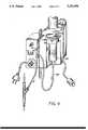
- FIG. 3is a cross-sectional view of the patient-controlled analgesic device taken along the line 3--3 in FIG. 2;
- FIG. 4is a perspective view of the patient-controlled analgesic device mounted in an electronic unit capable of administering beneficial agent to the patient at pre-selected time intervals.
- the patient-controlled analgesic device 10 of the present inventionincludes a housing 11. Housing 11 forms mounting pins 12, 13 to which wrist band portions 14, 15 may be secured.
- the wrist band portionsmay be Velcro® or other bands that are capable of mating and securing the device to a wrist.
- the device 10may thus be worn in the same manner as a watch.
- the housing 11 of the device 10includes a casing 16 and a back plate 17 secured to the casing, as for example with a plurality of screws (not shown).
- a portion of the back plate 17forms a raised plateau 18 that forms one wall of a dose reservoir 30.
- Back plate 17further includes a dose reservoir inlet 19 in communication with the dose reservoir and a dose reservoir outlet 20 also in communication with the dose reservoir.
- the outlet 20includes a disc valve 21, and valve seal 21a to sealingly engage disc valve 21 in communication with dose reservoir 30.
- Disc valve 21is normally closed so that beneficial agent drawn into dose reservoir 30 is retained therein until expressed out of the device 10 by the patient, as will be more fully described below.
- the dose reservoir inlet 19may include a valve means (not shown) or flow restrictive means (not shown) to limit backflow of beneficial agent through the inlet during operation of the device.
- pump means 23has an annular cross section.
- Pump means 23comprises a foot portion 24, an arcuate leg portion 25 and a head 26.
- the foot portion 24 of pump means 23lies adjacent the plateau portion 18 of the back plate 17 and is in sealing engagement therewith.
- Arcuate-shaped leg portion 25curves upwardly from foot portion 24 to head 26 of pump means 23.
- Head 26 of pump means 23extends upwardly through annular opening 22 in casing 16 to facilitate access of the pump means to an external force, such as, for example, the patient.
- the interior portion 25a of arcuate-shaped leg portion 25 and the interior portion 26a of head 26 of pump means 23 together with the plateau 18 of back plate 17define dose reservoir 30.
- pump means 23is designed so that it will draw beneficial liquid from a supply source 35, through conduit means 40 into dose reservoir 30 at a constant rate. It has been found that to accomplish that end, the arcuate-shaped portion 25 of pump means 23 should have a constant curvature over its entire length from foot portion 24 to head 26 and head 26 should be sufficiently rigid so that when pump means 23 is acted upon by an external force the arcuate-shaped leg portion 25 of pump means 23 will collapse under that force.
- the pump meansso designed provides a substantially linear recovery rate throughout its entire range of motion relative to the dose reservoir.
- the rate at which the collapsed pump means recovers from a collapsed condition to its fully uncompressed starting positionis linear over its entire stroke, from a fully compressed condition, as for example when the dose reservoir is completely emptied, to its original uncompressed condition, as for example when the dose reservoir is completely filled, and at all points between those two conditions.
- the linear recovery rate of the pump meansprovides a constant suction to draw beneficial liquid from external supply source 35 into dose reservoir 30.
- head 26returns to its original position at a controlled and linear rate. Accordingly, regardless of the position of the head relative to the dose reservoir after expressing beneficial agent from the dose reservoir by depressing the head, the incremental amount of beneficial agent drawn into the dose reservoir as the head rebounds to its original uncompressed position is directly proportional to the time the head was depressed by the external force.
- the recovery time to completely refill an emptied dose reservoiris T
- the recovery timewill be one-half T for a dose reservoir that is only one-half emptied and one-fourth T for a dose reservoir that is only one-fourth emptied, et cetera.
- the pump meansis preferably constructed of a resilient material which is biocompatible with the human body and is likewise compatible with the beneficial agent to be administered to the patient.
- a resilient materialwhich is biocompatible with the human body and is likewise compatible with the beneficial agent to be administered to the patient.
- silicone rubberis an acceptable resilient material.
- other elastomerscan be used to construct the pump means.
- pump means 23comprises a silicone rubber having a durometer of 30 to 50 (Shore A).
- a 30 to 50 durometer for the silicone elastomer pump meansprovides sufficient elasticity to perform the functions of both drawing beneficial agent from a supply source into the dose reservoir and expressing beneficial agent from the dose reservoir to the patient. It will be appreciated that a change in the durometer of the elastomer used for the pump means will affect the drawing power of the pump means and may thus affect the rate at which the dose reservoir is filled. For example, the greater the elastomer durometer, the greater the drawing power of the pump means will be.
- the head 26 of pump means 23is more rigid than the arcuate-shaped leg portion 25.
- the pump meansis a unitary structure so that head 26 must be thicker than the arcuate-shaped leg portion to impart the necessary rigidity to the head.
- head 26must be sufficiently thick so that when external pressure is applied to it, pump means 23 is compressed by collapse of the arcuate-shaped leg portion 25. That is, the head 26 is sufficiently thick that it does not compress significantly under the externally-applied force.
- the arcuate-shaped leg portion 25has a constant curvature over its entire length, and will collapse under the application of an external force in order to express beneficial agent out of the outlet means and to the patient.
- pump means 23is formed from a silicone rubber elastomer with a durometer of 30 to 50 (Shore A), and the arcuate-shaped leg portion 25 has a thickness (in cross-section) of about two-thirds the thickness of head 26. It is especially preferred for such pump means that the head have a thickness of about 0.12 inch and the arcuate-shaped leg portion 25 have a width of about 0.08 inch.
- the arcuate-shaped leg portion 25has a uniform radius of curvature over its entire length, and together with head 26 define a pump means 23 having an annular area of constant cross-section.
- the resilient compressible pump means 23assumes a first uncompressed condition.
- the patient-controlled apparatusmay be primed for subsequent use by the patient by filling the dose reservoir with liquid and removing air from the apparatus.
- pump means 23is operable in response to the application of an external force applied to head 26 of pump means 23.
- the external forcemay be, for example, the finger or thumb of the patient pushing downwardly on head 26.
- the arcuate-shaped leg portion 25collapses.
- the normally closed valve means 21 in outlet means 20opens and beneficial agent is expressed from the dose reservoir, through the outlet means to the patient.
- the valve means 21remains open as long as the external force is applied to the pump means. However, during that time the maximum amount of beneficial agent that will be expressed to the patient is a full dose.
- valve means 21Upon release of the external force, the resilient pump means tends to rebound to its first uncompressed condition, valve means 21 returns to its normally closed position and the dose reservoir is sealed. Thus, as pump means 23 rebounds to its first uncompressed condition, at least a partial vacuum is created in the dose reservoir. The vacuum in the dose reservoir is sufficient to draw beneficial liquid from an external supply source 35 through conduit means 40 and into dose reservoir 30 to replenish beneficial agent that was expressed from the device. Because of the design of the pump means, it rebounds to its first uncompressed condition at a relatively constant rate and, therefore, liquid is likewise drawn from external supply source 35 into dose reservoir 30 at a relatively constant rate.
- the dose reservoir 30is filled in a predetermined time period which will depend on the volume of dose reservoir, the pump means employed and the restriction means, if any, between the beneficial agent supply source 35 and the device 10. It will be appreciated, however, that a patient-controlled analgesic device with a particular pumping rate and dose reservoir volume when manufactured may be used for a variety of dosage requirements by adjusting the concentration of beneficial agent in the supply source to be delivered to the device.
- a patient who has depressed head 26 of pump means 23 and has thereby received a dose of beneficial agentmay receive another full dose of beneficial agent after the expiration of predetermined refill time period T. While the patient may wait longer than the predetermined time period T if desired, the patient must wait at least the predetermined time period T in order to receive a full dose. However, if the patient depresses pump means 23 sometime before the predetermined time period T required to fill the dose reservoir has expired, the patient will receive only a fraction of the full dose. Because the rebound rate of the pump means is linear over the entire range of completely empty to completely filled, the dose fraction that the patient receives will be equal to the fraction of the refill time period T that has elapsed during the patient's intermittent demand for beneficial agent.
- the patientdepresses the pump means at a time equal to one-half the predetermined fill time T, the patient will receive only one-half of a full dose volume. Thus no matter how often the patient depresses the pump means, he will never receive more than a single full dose of beneficial agent during the predetermined fill period T.
- pump mean 23 of the patient-controlled analgesic device 10 of the present inventionis capable of drawing beneficial liquid into the dose reservoir 30 at a linear rate
- the precise rate at which liquid is drawnmay be controlled by suitably restricting the rate at which the beneficial liquid is drawn from the supply source.
- either the inlet means itselfmay be designed to limit its rate of flow, or some other restrictive means within the supply source or between the supply source and the inlet means may be used.
- a conventional administration setis used to control the rate at which beneficial agent is drawn from the supply source.
- Such administrative setsare available with flow restrictive orifices of a fixed or adjustable design and may be used advantageously in combination with the patient controlled analgesic device of the present invention to control the rate at which beneficial agent is delivered from the supply source.
- the device 10 of the present inventionmay be used with automated equipment to deliver a dose of beneficial agent continuously or automatically at timed intervals, particularly when the patient is asleep.
- the automated equipmentis capable of automatically depressing the pump means 23 of the device 10 at preset intervals and may be relatively inexpensive compared to a separate automated pump and power source. It need not be a sophisticated electronic pump because all metering and dosing of beneficial agent will still be done by the device 10, without an external pump.
- the automated equipmentmay carry a patient override to permit the patient to override the preset intervals for dose administration. Dosing with such an arrangement is still controlled by the device 10 itself, as previously described, so that patient overdosing is precluded.
- the present inventionthus provides an accurate, self-driven, low-cost patient controlled analgesic apparatus that is versatile in use. It can be used by ambulatory patients during their waking hours and it can be readily adapted for use by patients at night with relatively inexpensive automated equipment.
Landscapes
- Health & Medical Sciences (AREA)
- Vascular Medicine (AREA)
- Engineering & Computer Science (AREA)
- Anesthesiology (AREA)
- Biomedical Technology (AREA)
- Heart & Thoracic Surgery (AREA)
- Hematology (AREA)
- Life Sciences & Earth Sciences (AREA)
- Animal Behavior & Ethology (AREA)
- General Health & Medical Sciences (AREA)
- Public Health (AREA)
- Veterinary Medicine (AREA)
- Infusion, Injection, And Reservoir Apparatuses (AREA)
Abstract
Description
Claims (19)
Priority Applications (1)
| Application Number | Priority Date | Filing Date | Title |
|---|---|---|---|
| US07/782,916US5232448A (en) | 1989-12-05 | 1991-10-25 | Patient-controlled analgesia device |
Applications Claiming Priority (2)
| Application Number | Priority Date | Filing Date | Title |
|---|---|---|---|
| US44618289A | 1989-12-05 | 1989-12-05 | |
| US07/782,916US5232448A (en) | 1989-12-05 | 1991-10-25 | Patient-controlled analgesia device |
Related Parent Applications (1)
| Application Number | Title | Priority Date | Filing Date |
|---|---|---|---|
| US44618289AContinuation | 1989-12-05 | 1989-12-05 |
Publications (1)
| Publication Number | Publication Date |
|---|---|
| US5232448Atrue US5232448A (en) | 1993-08-03 |
Family
ID=27034530
Family Applications (1)
| Application Number | Title | Priority Date | Filing Date |
|---|---|---|---|
| US07/782,916Expired - LifetimeUS5232448A (en) | 1989-12-05 | 1991-10-25 | Patient-controlled analgesia device |
Country Status (1)
| Country | Link |
|---|---|
| US (1) | US5232448A (en) |
Cited By (24)
| Publication number | Priority date | Publication date | Assignee | Title |
|---|---|---|---|---|
| US5531702A (en)* | 1995-05-04 | 1996-07-02 | Massillon Community Hospital | Patient controlled self injection aid |
| US5616132A (en)* | 1995-06-09 | 1997-04-01 | Subot, Inc. | Injection device |
| US5843014A (en)* | 1995-03-24 | 1998-12-01 | Alza Corporation | Display for an electrotransport delivery device |
| US5957885A (en)* | 1996-11-06 | 1999-09-28 | Alaris Medical Systems, Inc. | Oximetry monitored, patient controlled analgesia system |
| US6126642A (en)* | 1998-10-02 | 2000-10-03 | Science Incorporated | Patient controlled fluid delivery device |
| US6171294B1 (en) | 1995-06-05 | 2001-01-09 | Alza Corporation | Method and device for transdermal electrotransport delivery of fentanyl and sufentanil |
| US6216033B1 (en) | 1996-05-22 | 2001-04-10 | Alza Corporation | Device for transdermal electrotransport delivery of fentanyl and sufentanil |
| US6322542B1 (en)* | 1997-12-19 | 2001-11-27 | Astrazeneca Ab | Device for delivering liquid containing medicament |
| US6425892B2 (en) | 1995-06-05 | 2002-07-30 | Alza Corporation | Device for transdermal electrotransport delivery of fentanyl and sufentanil |
| US6516749B1 (en) | 1999-06-18 | 2003-02-11 | Salasoft, Inc. | Apparatus for the delivery to an animal of a beneficial agent |
| WO2003053503A1 (en) | 2001-12-06 | 2003-07-03 | Alaris Medical Systems, Inc. | Co2 monitored drug infusion system |
| US6881208B1 (en) | 1995-06-05 | 2005-04-19 | Joseph B. Phipps | Method and device for transdermal electrotransport delivery of fentanyl and sufentanil |
| DE202004016797U1 (en)* | 2004-10-30 | 2006-03-09 | Müller, Jost, Dr. Dr. med. | Device for medical infusions |
| WO2005089836A3 (en)* | 2004-03-17 | 2006-04-06 | Thomas Gotthard Ruttmann | Apparatus and method for dispensing a liquid |
| US20080132973A1 (en)* | 2006-11-28 | 2008-06-05 | Peter Carl Lord | Method, Apparatus and System For Assigning Remote Control Device to Ambulatory Medical Device |
| US20090264855A1 (en)* | 1995-06-05 | 2009-10-22 | Alza Corporation | Method and Device for Transdermal Electrotransport Delivery of Fentanyl and Sufentanil |
| US7806852B1 (en) | 2006-04-03 | 2010-10-05 | Jurson Phillip A | Method and apparatus for patient-controlled medical therapeutics |
| US20110137134A1 (en)* | 2007-01-17 | 2011-06-09 | Thomas Hemmerling | Method and system for administering an anaesthetic |
| WO2013049070A1 (en)* | 2011-09-26 | 2013-04-04 | Medipacs, Inc. | Low profile infusion pump with anti drug diversion and active feedback mechanisms |
| US8428709B1 (en) | 2012-06-11 | 2013-04-23 | Incline Therapeutics, Inc. | Current control for electrotransport drug delivery |
| US8428708B1 (en) | 2012-05-21 | 2013-04-23 | Incline Therapeutics, Inc. | Self-test for analgesic product |
| US8781571B2 (en) | 2011-03-31 | 2014-07-15 | Incline Therapeutics, Inc. | Switch validation circuit and method |
| US9731121B2 (en) | 2011-03-31 | 2017-08-15 | Incline Therapeutics, Inc. | Switch validation circuit and method |
| US20170239417A1 (en)* | 2007-12-31 | 2017-08-24 | Deka Products Limited Partnership | Apparatus, System and Method for Fluid Delivery |
Citations (19)
| Publication number | Priority date | Publication date | Assignee | Title |
|---|---|---|---|---|
| US3503402A (en)* | 1966-03-23 | 1970-03-31 | Rudolf R Schulte | Shunt device |
| US3827439A (en)* | 1972-10-30 | 1974-08-06 | Heyer Schulte Corp | Plug valve for physiological shunt systems |
| US4121584A (en)* | 1976-10-15 | 1978-10-24 | R. Scott Turner | Method and apparatus for controlling the dispensing of fluid |
| US4262668A (en)* | 1979-04-06 | 1981-04-21 | Baxter Travenol Laboratories, Inc. | Fixed volume infusion device |
| US4544371A (en)* | 1982-10-05 | 1985-10-01 | American Hospital Supply Corporation | Implantable metered dose drug delivery system |
| US4548607A (en)* | 1983-04-13 | 1985-10-22 | Cordis Corporation | Implantable manually actuated medication dispensing system |
| US4560375A (en)* | 1983-06-30 | 1985-12-24 | Pudenz-Schulte Medical Research Corp. | Flow control valve |
| US4588394A (en)* | 1984-03-16 | 1986-05-13 | Pudenz-Schulte Medical Research Corp. | Infusion reservoir and pump system |
| US4596558A (en)* | 1985-09-13 | 1986-06-24 | Queen's University At Kingston | Pulsed external medication dispenser |
| US4601707A (en)* | 1980-06-03 | 1986-07-22 | Albisser Anthony M | Insulin infusion device |
| US4623330A (en)* | 1982-02-16 | 1986-11-18 | Laby Ralph H | Gas diffusion-limited controlled release devices |
| US4627839A (en)* | 1985-11-21 | 1986-12-09 | American Hospital Supply Corporation | Patient controlled analgesia conversion |
| US4634427A (en)* | 1984-09-04 | 1987-01-06 | American Hospital Supply Company | Implantable demand medication delivery assembly |
| WO1987000758A1 (en)* | 1985-08-06 | 1987-02-12 | Baxter Travenol Laboratories, Inc. | Patient-controlled delivery of beneficial agents |
| US4668231A (en)* | 1984-02-15 | 1987-05-26 | Cordis Corporation | Implantable hand-operable dispensers for fluid medicaments |
| US4699615A (en)* | 1984-06-21 | 1987-10-13 | Fischell David R | Finger actuated medication infusion system |
| US4828551A (en)* | 1987-10-13 | 1989-05-09 | Gertler Robert A | Patient controlled analgesia apparatus |
| US4898585A (en)* | 1988-05-18 | 1990-02-06 | Baxter Healthcare Corporation | Implantable patient-activated fluid delivery device with bolus injection port |
| US4898584A (en)* | 1988-05-18 | 1990-02-06 | Baxter Healthcare Corporation | Implantable patient-activated fluid delivery device |
- 1991
- 1991-10-25USUS07/782,916patent/US5232448A/ennot_activeExpired - Lifetime
Patent Citations (19)
| Publication number | Priority date | Publication date | Assignee | Title |
|---|---|---|---|---|
| US3503402A (en)* | 1966-03-23 | 1970-03-31 | Rudolf R Schulte | Shunt device |
| US3827439A (en)* | 1972-10-30 | 1974-08-06 | Heyer Schulte Corp | Plug valve for physiological shunt systems |
| US4121584A (en)* | 1976-10-15 | 1978-10-24 | R. Scott Turner | Method and apparatus for controlling the dispensing of fluid |
| US4262668A (en)* | 1979-04-06 | 1981-04-21 | Baxter Travenol Laboratories, Inc. | Fixed volume infusion device |
| US4601707A (en)* | 1980-06-03 | 1986-07-22 | Albisser Anthony M | Insulin infusion device |
| US4623330A (en)* | 1982-02-16 | 1986-11-18 | Laby Ralph H | Gas diffusion-limited controlled release devices |
| US4544371A (en)* | 1982-10-05 | 1985-10-01 | American Hospital Supply Corporation | Implantable metered dose drug delivery system |
| US4548607A (en)* | 1983-04-13 | 1985-10-22 | Cordis Corporation | Implantable manually actuated medication dispensing system |
| US4560375A (en)* | 1983-06-30 | 1985-12-24 | Pudenz-Schulte Medical Research Corp. | Flow control valve |
| US4668231A (en)* | 1984-02-15 | 1987-05-26 | Cordis Corporation | Implantable hand-operable dispensers for fluid medicaments |
| US4588394A (en)* | 1984-03-16 | 1986-05-13 | Pudenz-Schulte Medical Research Corp. | Infusion reservoir and pump system |
| US4699615A (en)* | 1984-06-21 | 1987-10-13 | Fischell David R | Finger actuated medication infusion system |
| US4634427A (en)* | 1984-09-04 | 1987-01-06 | American Hospital Supply Company | Implantable demand medication delivery assembly |
| WO1987000758A1 (en)* | 1985-08-06 | 1987-02-12 | Baxter Travenol Laboratories, Inc. | Patient-controlled delivery of beneficial agents |
| US4596558A (en)* | 1985-09-13 | 1986-06-24 | Queen's University At Kingston | Pulsed external medication dispenser |
| US4627839A (en)* | 1985-11-21 | 1986-12-09 | American Hospital Supply Corporation | Patient controlled analgesia conversion |
| US4828551A (en)* | 1987-10-13 | 1989-05-09 | Gertler Robert A | Patient controlled analgesia apparatus |
| US4898585A (en)* | 1988-05-18 | 1990-02-06 | Baxter Healthcare Corporation | Implantable patient-activated fluid delivery device with bolus injection port |
| US4898584A (en)* | 1988-05-18 | 1990-02-06 | Baxter Healthcare Corporation | Implantable patient-activated fluid delivery device |
Non-Patent Citations (12)
| Title |
|---|
| "A patient education program for a continuous infusion regimen on an outpatient basis," by Roos Nieweg, R.N., Janke Greidanus, M.D. and Elisabeth G. E. de Vries, M.D. Career Nursing™, vol. 10(4), 1987. |
| A patient education program for a continuous infusion regimen on an outpatient basis, by Roos Nieweg, R.N., Janke Greidanus, M.D. and Elisabeth G. E. de Vries, M.D. Career Nursing , vol. 10(4), 1987.* |
| Brochure "Infu-Med 400". |
| Brochure Infu Med 400 .* |
| Clinical Note "Epidural administration of opiates by a new device", by F. Ingemar H. Ahlgren and Margareta B. E. Ahlgren, Pain, vol. 31 (1987). |
| Clinical Note Epidural administration of opiates by a new device , by F. Ingemar H. Ahlgren and Margareta B. E. Ahlgren, Pain, vol. 31 (1987).* |
| Primer "High-technology i.v. infusion devices," by Jane W. Kwan, American Journal of Hospital Pharmacy, vol. 46, Feb. 1989. |
| Primer High technology i.v. infusion devices, by Jane W. Kwan, American Journal of Hospital Pharmacy, vol. 46, Feb. 1989.* |
| Research "Evaluation of a disposable, nonelectronic, patient-controlled-analgesia device for postoperative pain" by Daniel P. Wermeling, Thomas S. Foster, Robert P. Rapp and Daniel E. Kenady, Clinical Pharmacy, vol. 6, Apr. 1987. |
| Research "Infusion phlebitis association with a programmble syringe-pump system versus gravity-feed minibottles," by Richard J. Baptista, David F. Driscoll, Janis A. Gallagher, Eva O'Keefe, Gregory J. Dumas, Scott M. Hammer and Philip P. Pacella, Clinical Pharmacy, vol. 6, Apr. 1987. |
| Research Evaluation of a disposable, nonelectronic, patient controlled analgesia device for postoperative pain by Daniel P. Wermeling, Thomas S. Foster, Robert P. Rapp and Daniel E. Kenady, Clinical Pharmacy, vol. 6, Apr. 1987.* |
| Research Infusion phlebitis association with a programmble syringe pump system versus gravity feed minibottles, by Richard J. Baptista, David F. Driscoll, Janis A. Gallagher, Eva O Keefe, Gregory J. Dumas, Scott M. Hammer and Philip P. Pacella, Clinical Pharmacy, vol. 6, Apr. 1987.* |
Cited By (43)
| Publication number | Priority date | Publication date | Assignee | Title |
|---|---|---|---|---|
| US5843014A (en)* | 1995-03-24 | 1998-12-01 | Alza Corporation | Display for an electrotransport delivery device |
| US5531702A (en)* | 1995-05-04 | 1996-07-02 | Massillon Community Hospital | Patient controlled self injection aid |
| US20060275352A1 (en)* | 1995-06-05 | 2006-12-07 | Mary Southam | Device for transdermal electrotransport delivery of fentanyl and sufentanil |
| US20050171464A1 (en)* | 1995-06-05 | 2005-08-04 | Phipps Joseph B. | Method and device for transdermal electrotransport delivery of fentanyl and sufentanil |
| US20090264855A1 (en)* | 1995-06-05 | 2009-10-22 | Alza Corporation | Method and Device for Transdermal Electrotransport Delivery of Fentanyl and Sufentanil |
| US6171294B1 (en) | 1995-06-05 | 2001-01-09 | Alza Corporation | Method and device for transdermal electrotransport delivery of fentanyl and sufentanil |
| US7302293B2 (en) | 1995-06-05 | 2007-11-27 | Alza Corporation | Device for transdermal electrotransport delivery of fentanyl and sufentanil |
| US8200327B2 (en) | 1995-06-05 | 2012-06-12 | Alza Corporation | Device for transdermal electrotransport delivery of fentanyl and sufentanil |
| US6425892B2 (en) | 1995-06-05 | 2002-07-30 | Alza Corporation | Device for transdermal electrotransport delivery of fentanyl and sufentanil |
| US20060069344A1 (en)* | 1995-06-05 | 2006-03-30 | Mary Southam | Device for transdermal electrotransport delivery of fentanyl and sufentanil |
| US7018370B2 (en) | 1995-06-05 | 2006-03-28 | Alza Corporation | Device for transdermal electrotransport delivery of fentanyl and sufentanil |
| US6881208B1 (en) | 1995-06-05 | 2005-04-19 | Joseph B. Phipps | Method and device for transdermal electrotransport delivery of fentanyl and sufentanil |
| US20050131337A1 (en)* | 1995-06-05 | 2005-06-16 | Phipps Joseph B. | Method and device for transdermal delivery of fentanyl and sufentanil |
| US5616132A (en)* | 1995-06-09 | 1997-04-01 | Subot, Inc. | Injection device |
| US6216033B1 (en) | 1996-05-22 | 2001-04-10 | Alza Corporation | Device for transdermal electrotransport delivery of fentanyl and sufentanil |
| US5957885A (en)* | 1996-11-06 | 1999-09-28 | Alaris Medical Systems, Inc. | Oximetry monitored, patient controlled analgesia system |
| US6322542B1 (en)* | 1997-12-19 | 2001-11-27 | Astrazeneca Ab | Device for delivering liquid containing medicament |
| US6126642A (en)* | 1998-10-02 | 2000-10-03 | Science Incorporated | Patient controlled fluid delivery device |
| US6516749B1 (en) | 1999-06-18 | 2003-02-11 | Salasoft, Inc. | Apparatus for the delivery to an animal of a beneficial agent |
| WO2003053503A1 (en) | 2001-12-06 | 2003-07-03 | Alaris Medical Systems, Inc. | Co2 monitored drug infusion system |
| EP2289584A1 (en) | 2001-12-06 | 2011-03-02 | CareFusion 303, Inc. | CO2 monitored drug infusion system |
| WO2005089836A3 (en)* | 2004-03-17 | 2006-04-06 | Thomas Gotthard Ruttmann | Apparatus and method for dispensing a liquid |
| DE202004016797U1 (en)* | 2004-10-30 | 2006-03-09 | Müller, Jost, Dr. Dr. med. | Device for medical infusions |
| US7806852B1 (en) | 2006-04-03 | 2010-10-05 | Jurson Phillip A | Method and apparatus for patient-controlled medical therapeutics |
| US20080132973A1 (en)* | 2006-11-28 | 2008-06-05 | Peter Carl Lord | Method, Apparatus and System For Assigning Remote Control Device to Ambulatory Medical Device |
| US9135810B2 (en) | 2006-11-28 | 2015-09-15 | Medallion Therapeutics, Inc. | Method, apparatus and system for assigning remote control device to ambulatory medical device |
| US20110137134A1 (en)* | 2007-01-17 | 2011-06-09 | Thomas Hemmerling | Method and system for administering an anaesthetic |
| US20170239417A1 (en)* | 2007-12-31 | 2017-08-24 | Deka Products Limited Partnership | Apparatus, System and Method for Fluid Delivery |
| US12128006B2 (en)* | 2007-12-31 | 2024-10-29 | Deka Products Limited Partnership | Apparatus, system and method for fluid delivery |
| US20240108546A1 (en)* | 2007-12-31 | 2024-04-04 | Deka Products Limited Partnership | Apparatus, system and method for fluid delivery |
| US11723841B2 (en)* | 2007-12-31 | 2023-08-15 | Deka Products Limited Partnership | Apparatus, system and method for fluid delivery |
| US20220387260A1 (en)* | 2007-12-31 | 2022-12-08 | Deka Products Limited Partnership | Apparatus, system and method for fluid delivery |
| US11389377B2 (en) | 2007-12-31 | 2022-07-19 | Deka Products Limited Partnership | Apparatus, system and method for fluid delivery |
| US10926030B2 (en)* | 2007-12-31 | 2021-02-23 | Deka Products Limited Partnership | Apparatus, system and method for fluid delivery |
| US8781571B2 (en) | 2011-03-31 | 2014-07-15 | Incline Therapeutics, Inc. | Switch validation circuit and method |
| US9731121B2 (en) | 2011-03-31 | 2017-08-15 | Incline Therapeutics, Inc. | Switch validation circuit and method |
| CN104080491A (en)* | 2011-09-26 | 2014-10-01 | 麦德医像公司 | Low profile infusion pump with anti drug diversion and active feedback mechanisms |
| WO2013049070A1 (en)* | 2011-09-26 | 2013-04-04 | Medipacs, Inc. | Low profile infusion pump with anti drug diversion and active feedback mechanisms |
| US9645179B2 (en) | 2012-05-21 | 2017-05-09 | Incline Therapeutics, Inc. | Self-test for analgesic product |
| US9095706B2 (en) | 2012-05-21 | 2015-08-04 | Incline Therapeutics, Inc. | Self-test for analgesic product |
| US8428708B1 (en) | 2012-05-21 | 2013-04-23 | Incline Therapeutics, Inc. | Self-test for analgesic product |
| US9919151B2 (en) | 2012-06-11 | 2018-03-20 | Incline Therapeutics, Inc. | Current control for electrotransport drug delivery |
| US8428709B1 (en) | 2012-06-11 | 2013-04-23 | Incline Therapeutics, Inc. | Current control for electrotransport drug delivery |
Similar Documents
| Publication | Publication Date | Title |
|---|---|---|
| US5232448A (en) | Patient-controlled analgesia device | |
| AU622514B2 (en) | Patient-controlled delivery of beneficial agents | |
| EP1083949B1 (en) | Patient-controlled drug administration device | |
| JP4398723B2 (en) | Large-capacity bolus device | |
| US6656159B2 (en) | Dispenser for patient infusion device | |
| US8758308B2 (en) | Infusion device pump | |
| EP0504255B1 (en) | Self-driven pump device | |
| US20040153032A1 (en) | Dispenser for patient infusion device | |
| US4687468A (en) | Implantable insulin administration device | |
| WO1992008514A1 (en) | Anesthesia at a continuing and decreasing rate | |
| US8052657B2 (en) | Method and devices for self-dosing a liquid medicament and for controlling the dosage of the same | |
| WO2005089836A2 (en) | Apparatus and method for dispensing a liquid |
Legal Events
| Date | Code | Title | Description |
|---|---|---|---|
| AS | Assignment | Owner name:PRIME MEDICAL PRODUCTS, INC., ILLINOIS Free format text:SECURITY AGREEMENT;ASSIGNOR:MCKINLEY INFUSER, INC;REEL/FRAME:007908/0055 Effective date:19960617 | |
| AS | Assignment | Owner name:MCKINLEY INFUSER, INC., COLORADO Free format text:ASSIGNMENT OF ASSIGNORS INTEREST;ASSIGNOR:PRIME MEDICAL PRODUCTS, INC.;REEL/FRAME:008040/0265 Effective date:19960617 | |
| FPAY | Fee payment | Year of fee payment:4 | |
| FPAY | Fee payment | Year of fee payment:8 | |
| AS | Assignment | Owner name:PRIME MEDICAL PRODUCTS, INC., FLORIDA Free format text:ASSIGNMENT OF ASSIGNORS INTEREST;ASSIGNORS:MCKINLEY INFUSER, INC., N/K/A MCKINLEY INFUSER ONE, INC., A CORP. OF COLORADO;MCKINLEY MEDICAL, L.L.P., A COLORADO LIMITED LIABILITY PARTNERSHIP;MCKINLEY, INC., A CORP. OF COLORADO;AND OTHERS;REEL/FRAME:014539/0201 Effective date:20030228 | |
| REMI | Maintenance fee reminder mailed | ||
| REIN | Reinstatement after maintenance fee payment confirmed | ||
| LAPS | Lapse for failure to pay maintenance fees | Free format text:PATENT EXPIRED FOR FAILURE TO PAY MAINTENANCE FEES (ORIGINAL EVENT CODE: EXP.); ENTITY STATUS OF PATENT OWNER: SMALL ENTITY | |
| FP | Lapsed due to failure to pay maintenance fee | Effective date:20050803 | |
| FEPP | Fee payment procedure | Free format text:PETITION RELATED TO MAINTENANCE FEES FILED (ORIGINAL EVENT CODE: PMFP); ENTITY STATUS OF PATENT OWNER: SMALL ENTITY | |
| FEPP | Fee payment procedure | Free format text:PETITION RELATED TO MAINTENANCE FEES GRANTED (ORIGINAL EVENT CODE: PMFG); ENTITY STATUS OF PATENT OWNER: SMALL ENTITY | |
| FPAY | Fee payment | Year of fee payment:12 | |
| SULP | Surcharge for late payment | ||
| PRDP | Patent reinstated due to the acceptance of a late maintenance fee | Effective date:20060215 | |
| STCF | Information on status: patent grant | Free format text:PATENTED CASE |