US5232439A - Method for pumping fluid from a flexible, variable geometry reservoir - Google Patents
Method for pumping fluid from a flexible, variable geometry reservoirDownload PDFInfo
- Publication number
- US5232439A US5232439AUS07/969,981US96998192AUS5232439AUS 5232439 AUS5232439 AUS 5232439AUS 96998192 AUS96998192 AUS 96998192AUS 5232439 AUS5232439 AUS 5232439A
- Authority
- US
- United States
- Prior art keywords
- chamber
- volume
- reservoir
- wall
- bag
- Prior art date
- Legal status (The legal status is an assumption and is not a legal conclusion. Google has not performed a legal analysis and makes no representation as to the accuracy of the status listed.)
- Expired - Fee Related
Links
- 239000012530fluidSubstances0.000titleclaimsabstractdescription62
- 238000000034methodMethods0.000titleclaimsabstractdescription36
- 238000005086pumpingMethods0.000titleabstractdescription4
- 230000009467reductionEffects0.000claimsabstractdescription10
- 238000011038discontinuous diafiltration by volume reductionMethods0.000claimsdescription15
- 239000003978infusion fluidSubstances0.000claimsdescription3
- 238000004364calculation methodMethods0.000abstractdescription10
- 238000001990intravenous administrationMethods0.000description37
- 238000012360testing methodMethods0.000description15
- 230000008859changeEffects0.000description9
- 230000008901benefitEffects0.000description8
- 230000007423decreaseEffects0.000description6
- 230000006870functionEffects0.000description6
- 238000001802infusionMethods0.000description6
- 238000013459approachMethods0.000description4
- 239000000243solutionSubstances0.000description4
- 238000011282treatmentMethods0.000description3
- 208000032366OversensingDiseases0.000description2
- 230000004913activationEffects0.000description2
- 230000003247decreasing effectEffects0.000description2
- 230000037452primingEffects0.000description2
- 208000035143Bacterial infectionDiseases0.000description1
- 208000000094Chronic PainDiseases0.000description1
- 208000005016Intestinal NeoplasmsDiseases0.000description1
- 208000002193PainDiseases0.000description1
- 230000003213activating effectEffects0.000description1
- 208000022362bacterial infectious diseaseDiseases0.000description1
- 230000005540biological transmissionEffects0.000description1
- 230000001684chronic effectEffects0.000description1
- 238000011109contaminationMethods0.000description1
- 239000013078crystalSubstances0.000description1
- 238000010586diagramMethods0.000description1
- 238000006073displacement reactionMethods0.000description1
- 239000003792electrolyteSubstances0.000description1
- 230000005672electromagnetic fieldEffects0.000description1
- 238000005265energy consumptionMethods0.000description1
- 230000005484gravityEffects0.000description1
- 208000014951hematologic diseaseDiseases0.000description1
- 230000000887hydrating effectEffects0.000description1
- 238000002347injectionMethods0.000description1
- 239000007924injectionSubstances0.000description1
- 238000003780insertionMethods0.000description1
- 230000037431insertionEffects0.000description1
- 201000002313intestinal cancerDiseases0.000description1
- 208000028774intestinal diseaseDiseases0.000description1
- 238000010253intravenous injectionMethods0.000description1
- 238000012423maintenanceMethods0.000description1
- 239000010453quartzSubstances0.000description1
- 230000004044responseEffects0.000description1
- 230000000717retained effectEffects0.000description1
- VYPSYNLAJGMNEJ-UHFFFAOYSA-Nsilicon dioxideInorganic materialsO=[Si]=OVYPSYNLAJGMNEJ-UHFFFAOYSA-N0.000description1
- 238000012546transferMethods0.000description1
- 230000002792vascularEffects0.000description1
- 230000000007visual effectEffects0.000description1
Images


Classifications
- A—HUMAN NECESSITIES
- A61—MEDICAL OR VETERINARY SCIENCE; HYGIENE
- A61M—DEVICES FOR INTRODUCING MEDIA INTO, OR ONTO, THE BODY; DEVICES FOR TRANSDUCING BODY MEDIA OR FOR TAKING MEDIA FROM THE BODY; DEVICES FOR PRODUCING OR ENDING SLEEP OR STUPOR
- A61M5/00—Devices for bringing media into the body in a subcutaneous, intra-vascular or intramuscular way; Accessories therefor, e.g. filling or cleaning devices, arm-rests
- A61M5/14—Infusion devices, e.g. infusing by gravity; Blood infusion; Accessories therefor
- A61M5/168—Means for controlling media flow to the body or for metering media to the body, e.g. drip meters, counters ; Monitoring media flow to the body
- A61M5/16831—Monitoring, detecting, signalling or eliminating infusion flow anomalies
- A61M5/16854—Monitoring, detecting, signalling or eliminating infusion flow anomalies by monitoring line pressure
- A—HUMAN NECESSITIES
- A61—MEDICAL OR VETERINARY SCIENCE; HYGIENE
- A61M—DEVICES FOR INTRODUCING MEDIA INTO, OR ONTO, THE BODY; DEVICES FOR TRANSDUCING BODY MEDIA OR FOR TAKING MEDIA FROM THE BODY; DEVICES FOR PRODUCING OR ENDING SLEEP OR STUPOR
- A61M5/00—Devices for bringing media into the body in a subcutaneous, intra-vascular or intramuscular way; Accessories therefor, e.g. filling or cleaning devices, arm-rests
- A61M5/14—Infusion devices, e.g. infusing by gravity; Blood infusion; Accessories therefor
- A61M5/142—Pressure infusion, e.g. using pumps
- A61M5/145—Pressure infusion, e.g. using pumps using pressurised reservoirs, e.g. pressurised by means of pistons
- A61M5/148—Pressure infusion, e.g. using pumps using pressurised reservoirs, e.g. pressurised by means of pistons flexible, e.g. independent bags
- A—HUMAN NECESSITIES
- A61—MEDICAL OR VETERINARY SCIENCE; HYGIENE
- A61M—DEVICES FOR INTRODUCING MEDIA INTO, OR ONTO, THE BODY; DEVICES FOR TRANSDUCING BODY MEDIA OR FOR TAKING MEDIA FROM THE BODY; DEVICES FOR PRODUCING OR ENDING SLEEP OR STUPOR
- A61M39/00—Tubes, tube connectors, tube couplings, valves, access sites or the like, specially adapted for medical use
- A61M39/22—Valves or arrangement of valves
- A61M39/28—Clamping means for squeezing flexible tubes, e.g. roller clamps
- A61M39/281—Automatic tube cut-off devices, e.g. squeezing tube on detection of air
- Y—GENERAL TAGGING OF NEW TECHNOLOGICAL DEVELOPMENTS; GENERAL TAGGING OF CROSS-SECTIONAL TECHNOLOGIES SPANNING OVER SEVERAL SECTIONS OF THE IPC; TECHNICAL SUBJECTS COVERED BY FORMER USPC CROSS-REFERENCE ART COLLECTIONS [XRACs] AND DIGESTS
- Y10—TECHNICAL SUBJECTS COVERED BY FORMER USPC
- Y10S—TECHNICAL SUBJECTS COVERED BY FORMER USPC CROSS-REFERENCE ART COLLECTIONS [XRACs] AND DIGESTS
- Y10S128/00—Surgery
- Y10S128/12—Pressure infusion
Definitions
- the present inventionrelates to systems for administering intravenous (IV) fluid.
- the present inventionrelates to a positive displacement infusion pump and method for delivering a predetermined rate of flow of an IV fluid from a standard flexible intravenous bag to a patient.
- Intravenous injection of medicating, nourishing, hydrating or electrolyte replacing fluidsis an essential method for treating various medical conditions.
- the treatment of chronic bacterial infections, hematological disorders, intestinal disorders, cancer and chronic painoften require a continuous or recurring delivery of solutions by IV injection.
- the IV solutionsare pharmacologically prepared within a flexible bag.
- such treatmentshave been administered in a medical facility because of the equipment required to deliver the IV solution, and because of the medical personnel required to monitor the administration of the treatment.
- the present inventionis a method for delivering a predetermined rate of flow of an intravenous fluid from a standard flexible intravenous bag to a patient.
- the method of the present inventionutilizes an apparatus which includes a bag chamber for holding a standard, flexible, fluid-filled intravenous bag.
- the bag chamberwhich includes a moveable member and a stationary side opposite the moveable member, has an initial volume which is the largest when the moveable member is in a starting position.
- the bag chamberis sized to urge the bag to conform to the shape of the bag chamber such that when the moveable member moves toward the stationary side at a predetermined rate, a predetermined volume of fluid is expressed out of an outlet of the bag.
- the bag chamberwhen the bag chamber is at its initial volume, a contact area between a surface of the bag, the moveable member and the stationary side is relatively small. As the moveable member moves toward the stationary side, the contact area increases. Moreover, the volume of the chamber is greater than the volume of the bag and the relationship between the volumes changes nonlinearly as the volume of the chamber is reduced. In order to express fluid out of the bag outlet at a predetermined rate, the rate at which the moveable member moves toward the stationary side must be adjusted downward as the contact area increases or chamber volume decreases.
- Control meanscontrols the rate of movement of the moveable member toward the stationary side. This rate adjustment is determined according to a parameter related to the position of the moveable member that, when moved, results in variation in contact area, and a predetermined fluid delivery rate.
- the control meansthereby allows the infusion pump of the present invention to deliver a predetermined rate of fluid flow from the bag despite the changing contact area or chamber/bag volume relationship.
- the moveable memberis pivotally connected to the stationary side.
- the angular position of the moveable member relative to the stationary sidebears a relationship to the size of the area contacted by the sides and to the relationship of the volume of the chamber to the volume of the bag.
- the control meansdetermines the angular position of the moveable member relative to the stationary side (and hence the contact area and volume and rate relationships). The control adjusts the output signal to the motor to adjust the rate of movement of the moveable member as the moveable member approaches the stationary side in order to accurately control fluid flow.
- FIG. 1is an rear elevational view of the preferred embodiment of the portable pump system being worn by a patient.
- FIG. 2is a cross-sectional view of the preferred embodiment of the present invention.
- FIG. 3is a schematic representation of the chamber and reservoir of the preferred embodiment.
- FIGS. 4A-4Bare schematic representations of the chamber and reservoir of the preferred embodiment.
- FIG. 5is a graphic representation of a force ratio as a function of angular position of the moveable plate for the preferred embodiment.
- FIG. 6is a diagrammatic representation of the control, input and output systems of the preferred embodiment.
- FIG. 7is a elevational view of a first alternative embodiment of the present invention.
- FIG. 8is a top planar view of a second alternative embodiment of the present invention.
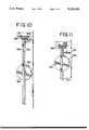
- FIGS. 9, 10 and 11are elevational views of the second alternative embodiment of FIG. 8, shown in time sequence as fluid is expressed from the bag.
- FIG. 1shows the preferred embodiment of backpack-type portable pump system 10 being carried by a patient.
- System 10generally includes container 12 and carrier straps 13.
- Container 12is designed to be carried on the back of a patient with straps 13 positioned over the shoulders of the patient.
- Container 12provides a discrete means for transporting pump system 10, which allows a patient to lead a relatively normal public life.
- Container 12includes top 12A, bottom 12B, left side wall 12C, right side wall 12D, back wall 12E and front wall 12F.
- Removable cover 14 in top 12Aexposes an interior of container 12 for receiving and holding flexible intravenous bag 15 (shown in phantom).
- bag 15Connected to bag 15 is catheter 16, which carries fluid from bag 15 to the vascular system of the patient when pump system 10 is operating.
- User interface 18is provided in right side wall 12D to select IV delivery parameters (such as flow rate in cc/hour or ml/hour) according to the prescribed needs of a patient, and to monitor operation of pump system 10.
- FIG. 2is a cross-sectional view of container 12 of the preferred embodiment of FIG. 1.
- Container 12generally includes bag chamber 20, pump drive 21 and moveable plate 22, which separates bag chamber 20 from pump drive 21.
- Bag chamber 20which is generally triangular shaped in cross section, is formed by stationary front wall 12F, removeable cover 14 of container 12, moveable plate 22 and opposing side walls 12C and 12D. Side walls 12C and 12D are perpendicular to stationary front wall 12F and moveable plate 22 and serve to constrain bag 15.
- bag chamber 20has a maximum volume which is capable of holding bag 15 when it contains up to 3 liters of fluid. Front wall 12F is rigid and provides a surface against which IV bag 15 is compressed during operation of pump system 10.
- Moveable plate 22is pivotally connected to front wall 12F by hinge 28.
- Moveable plate 22has a width which is approximately equal to a width of bag chamber 20, and which is slightly less than a width of bag 15. This tends to urge bag 15 to conform as much as possible to the shape of bag chamber 20.
- Moveable plate 22includes bag contact surface 32 which contacts and squeezes bag surface 34, to force fluid contained within bag 15 out bag outlet 30 to catheter 16.
- Removable cover 14is provided with opening 36 to accommodate the change in position of bag outlet 30 as a result of moveable plate 22 moving toward stationary front wall 12F of container 12.
- Pump drive 21is comprised of motor drive 15, assembly 38, controller 40, user interface 18, and power supply 44.
- Motor drive assembly 38is provided to drive moveable plate 22 toward front wall 12F of container 12.
- Motor drive assembly 38includes electric motor 48, lead screw 50, follower 52, and push rod 54.
- Motor 48is securely mounted to inner surface 49 of bottom 12B, with lead screw 50 oriented vertically toward cover 14.
- Motor 48which communicates with controller 40 by electrical connection 59, is preferably a stepper motor.
- Motor 48is capable of driving lead screw 50 one increment for each step command pulse provided to motor 48.
- a result of a continuing rotation of a magnet of motor 48 subsequent to each step command pulse, motor 48also generates an electromagnetic field ("back emf") back to controller 40 via connection 59.
- the lead screw 50includes external threads which are mated to internal threads of follower 52. As motor 48 rotates lead screw 50, follower 52 moves linearly along lead screw 50.
- Push rod 54is pivotally connected to moveable plate 22 at plate connection 58 and to follower 52 at follower connection 60.
- the linear movement of follower 52 along lead screw 50 away from motor 48causes push rod 54 to force moveable plate 22 toward stationary front wall 12F.
- follower 52moves toward motor 48 (i.e., when lead screw 50 rotates in an opposite direction)
- push rod 54applies a negative force to moveable plate 22 which pulls moveable plate 22 away from front wall 12F.
- Push rod 54has a length greater than the distance between lead screw 50 and front wall 12F to ensure that movement of follower 52 away from motor 48 will always result in a positive application of force to moveable plate 22. This also ensures that fluid always flows only from bag 15 to the patient. Motor 48 will not inadvertently counter-rotate the lead screw 50, such as in the unlikely event of an electrical failure. In the event of such a failure, therefore, moveable plate 22 will be immobilized in order to keep a positive pressure on surface 34 bag 15. This ensures that no fluid flow from the patient to bag 15 will occur.
- Pivotally connecting the bottom of moveable plate 22 to front wall 12Fprovides significant mechanical advantages.
- the pivotal arrangement at the bottom intersection of the moveable plate 22 to front wall 12Fallows easy insertion of the bag.
- the bagmay be simply placed into the triangular shaped chamber 20; the force of gravity assures that the bag settles in the lowest point, contacting both the moveable plate 22 and front wall 12.
- the pivotal arrangementprovides a mechanical leverage arrangement.
- Application of a force at the plate connection 59, relatively high on the moveable plate 12,provides an increased force at points along the plate between it and hinge 28.
- the relative forcesare illustrated in FIG. 3.
- the moment F n R 2must equal the moment F q R 1 when the system is in an equilibrium state. ##EQU1## which represents the mechanical advantage.
- Controller 40is preferably programmable digital circuitry which provides a step pulse output to motor 48 based upon flow rate inputs received from input user interface 18. Controller 40 regulates the frequency of the step pulse output to motor 48. Each step pulse from controller 40 corresponds to a known step advancement of motor 48. Controller 40 includes a counter or other memory device which records the number of step pulses provided to motor 48. The number of step pulses (and therefore the number of steps of motor 48) indicates the angular distance travelled by moveable plate 22.
- Controller 40implements (preferably by programmable logic) an algorithm for determining angular position of moveable plate 22, and therefore the contact area between bag surface 34, moveable plate 22 and front wall 12F, as a function of the number of steps of motor 48 recorded. Controller 40 determines, on a pulse-by-pulse basis, the frequency of pulses supplied to motor 48. The rate of pulses supplied to motor 48 varies as moveable plate 22 moves toward front wall 12F and the area of contact increases between bag surface 34, moveable plate 22 and front wall 12F. For each step pulse output, controller 40 determines the time to the next pulse output based upon the number of pulses recorded (i.e., angular position of plate 22) and the selected flow rate.
- User interface 18provides inputs to controller 40 through cable 70 to select the flow rate provided by controller 40. Input parameters such as flow rate, ramp-up time, ramp-down time, system prime or other parameters are provided to controller 40 by programming switches 42A (shown in FIG. 6). Programming switches 42A are preferably binary decimal switches or keys, thumb-wheel switches, or any other suitable programming means compatible with programmable digital circuitry. User interface 18 also includes diagnostic display lights 42B and audio transducer 42C (shown in FIG. 6), which provide feedback information from controller 40 that is related to performance of pump system 10.
- Power supply 44is electrically connected to controller 40 for energizing pump system 10.
- power source 44includes four AA batteries which are capable of operating pump system 10 for one complete IV delivery.
- FIGS. 4A and 4Bare graphical representations of the concept upon which the present invention is based.
- the present inventionis based upon the recognition that the area of contact between bag surface 34, moveable plate 22 and front wall 12F, and the relationship of the volume of the chamber to the volume of the reservoir and their respective rates of reduction, varies during movement of plate 22. Therefore, in order to express a predetermined volume of fluid from intravenous bag 15 at a predetermined rate, the rate of movement of plate 22 must compensate for these nonlinear relationships.
- a beginning contact area Al between bag surface 34, moveable plate 22 and front wall 12Fis determined when moveable plate 22 is actuated until fluid is forced completely through catheter 16.
- Beginning contact area A1corresponds to beginning angle ⁇ between moveable plate 22 and front wall 12F.
- contact area A2likewise corresponds to reduced angle ⁇ 2 between moveable plate 22 and front wall 12F.
- controller 40reduces the rate of movement of motor 48 (and hence of plate 22) to compensate for the increase in contact area.
- bag chamber 20is defined by the intersection of line C0, which represents front wall 12F, and line D0, which represents moveable plate 22.
- Point 0represents the location of hinge 28.
- the angular distance between moveable plate 22 and front wall 12Fis represented as angle ⁇ .
- Line 00'represents the linear distance of motor 48 from front wall 12F, which is represented by f.
- Point 0'indicates the position of motor 48 with line E0' representing lead screw 50.
- Line E0'is perpendicular to line 00' and parallel to line C0.
- Line ABrepresents push rod 54, where point A represents plate connection 59 and point B represents follower 52 and follower connection 60.
- the distance between plate connection 59 (point A) and hinge 28 (point 0)is represented as h, and the distance between plate connection 59 and follower connection 60 is shown by m.
- force vector F nthe force applied by push rod 54 to moveable plate 22 at plate connection 59 provides a rotational force component, shown by force vector F n , which moves moveable plate 22 toward front wall 12F.
- Force vector F nis perpendicular to moveable plate 22, with line AF representing an imaginary extension of force vector F n toward lead screw 50.
- the angular distance between push rod 54 and line AFis indicated by angle ⁇ .
- the programmable controller 40activates the frequency of pulses to the motor 48 in order to compensate for the difference between the volume reduction of the chamber 20 and the corresponding volume reduction of the bag 15, and the nonlinear variation of that relationship as the moveable plate 22 approaches the front wall 12F and the volume of the chamber is reduced.
- the volume of fluid expressed from the bag 15equals the reduction is bag volume and, in turn, the rate of fluid expressed from the bag equals the rate the bag volume is reduced. Control of the volume reduction and rate of volume reduction of the bag within a volume-reducible chamber is addressed as part of the present invention.
- the chamber volumeis represented by ⁇
- the incremental change of the volume at a given position of the approach of moveable plate 22 to front wall 12Fis represented by d ⁇ .
- the volume of the bagis represented by V
- the incremental change of the volume at a given position of the approach of moveable plate 22 to front wall 12Fis represented by dV.
- S.sub. ⁇is the relationship of bag volume reduction to chamber volume reduction at chamber volume ⁇ .
- S.sub. ⁇is determined empirically, mathematically or by a combination of empirical observation and mathematical calculations.
- the controller 40has a memory which can store the values of the change in bag volume dV to obtain the desired delivery of fluid to the patient and stores the predetermined values S.sub. ⁇ for the moveable plate 22 movement.
- the controllercalculates d ⁇ from the values of dV (which is the desired volume to be expressed from the bag 15) and S.sub. ⁇ in its memory for a given position ⁇ and actuates the motor to reduce the volume of the chamber d ⁇ to accomplish dV, the volume of fluid expressed from the bag 15 and to the patient.
- the six sets of values in Table 2are representative only; in actual use hundreds of values would be determined so that optimal precision in volume and rate of fluid delivery would be obtained.
- Determining S.sub. ⁇ for the entire range of moveable plate 22 movement and the desired volume of fluid dV to be delivered at that point in position and timeallows the d ⁇ , the change in chamber volume, i.e., the number of steps of the motor, to be determined. This allows for a predetermined, varying rate of flow to be accomplished with a relatively high degree of precision.
- a similar calculationcan be accomplished in the controller directly for rate of fluid flow by factoring in a time parameter.
- the rate of chamber volume reductioncan be expressed by the change in chamber volume d ⁇ divided by the corresponding change in time dt.
- R iis the incremental rate of fluid flow expressed from the bag 15 at specific chamber volume ⁇
- S Ris the relationship of rate of chamber volume reduction to fluid flow R i .
- the memory of the controller 40contains both the predetermined S r values for the various chamber volumes ⁇ and R i is the desired fluid flow which is in the memory, is introduced into the memory by the user, or is calculated by the controller from information supplied by the user.
- the controllercontrols the motor to the rate of reduction of the chamber volume from calculations of d ⁇ /dt from R i and S R values associated with a series of specific chamber volumes ⁇ .
- the S R valuescan be empirically determined, mathematically calculated, or calculated by a combination of empirical observations and mathematical calculations.
- a table similar to Table 2can be prepared for S R .
- the inventive principles disclosed hereinare applicable to a method as well as an apparatus.
- This methodallows for a controlled, relatively high precision delivery of fluid to a patient for varying volumes over time.
- the method of controlling the rates of deliverymerely factors the time parameter into the volume control.
- the methodincludes the steps of placing the reservoir or bag 15 into the chamber, electronically calculating in the controller the rate the volume of the chamber is to be reduced by the formula ##EQU6## from the values of R i and S R in the memory, and electronically activating the volume reducing means according to the calculation of the controller.
- This methodallows for controlled, relatively high precision delivery of fluid to a patient for varying rates such as a ramp-up, constant rate and ramp-down commonly used for IV fluid infusion.
- FIG. 5is a graph of force ratio F n as it relates to the changing angular position of moveable plate 22.
- the x axisrepresents in degrees angle ⁇ of moveable plate 22 relative to front wall 12F, as shown in FIG. 4.
- the y axisrepresents force ratio F n , which is the ratio of F n to F y .
- a plot of the values for F n obtained aboveis shown by curved line L.
- motor assembly 38may include a transmission or other gear train to divide down the incremental rotation of the motor assembly 38 into smaller increments of movement of lead screw 50.
- FIG. 6is a block diagram of pump system 10 of the present invention.
- Pump system 10which in a preferred embodiment is a five volt circuitry on average, is energized by power supply 44. Power is preferably supplied by four AA batteries which, at the beginning of an IV delivery, provide six volts. Power supply 44 is electrically connected to controller 40.
- controller 40includes programmable logic circuit (PLC) 90 (which implements the algorithms and logic necessary to control step pulse frequency as a function of the selected flow rate), clock 100, self test on power on circuit 102, stall sensing circuit 104, position sensing circuit 106, watch dog circuit 108, low battery sensing circuit 110, lock-out circuit 112, digitized audio chip 114, and tip over sensing switch 116.
- PLCprogrammable logic circuit
- Clock 100is a standard quartz crystal oscillator commonly used in any logic circuitry. Clock 100 provides the time reference necessary for real time operation of PLC 90. Clock 100 also communicates with watch dog circuit 108, which ensures that PLC 90 is operating in response to clock signals of clock 100.
- Self test on power on circuit 102performs an automatic test of the electrical integrity of pump system 10.
- Self test circuit 102ensures that all electrical input and output connections are intact when pump system 10 is energized. It also tests the electrical integrity of the circuitry of controller 40 and actuator driver motor 48.
- Stall sensing circuit 104senses current to motor 48 and provides an output signal in the event of an abrupt increase in current. In addition, stall sensing circuit 104 senses the back emf generated by motor 48. Stall sensing circuit 104, therefore, determines two elements. First, stall sensing circuit 104 detects any obstructions to fluid flow from bag 15. Stall sensing circuit 104 also determines any problems with motor drive assembly 38 itself. Any abrupt increases in current flow to motor 48 over a relatively short period of time, or any decrease in back emf results in an output signal which indicates pump system 10 is not operating properly.
- Position sensing circuit 106records the number of step pulse outputs to motor 48. Position sensing circuit 106 begins counting when the angular distance between moveable plate 22 and front wall 12F is at its greatest (i.e., step 0). The number of step pulse outputs from controller 40 to motor 48 corresponds to the number of steps of motor 48, which in turn relates to the angular distance traveled by moveable plate 22. For a uniform volume IV bag (e.g., three liters), the angular position of moveable plate 22 and the contact area between bag surface 34, moveable plate 22 and front wall 12F, are specific to the volume of fluid contained within bag 15.
- a uniform volume IV bage.g., three liters
- Low battery sensing circuit 110is a voltage comparator which measures the voltage of power supply 44 against a voltage referenced point, and cuts off power supply 44 if the voltage of power supply 44 falls below a predetermined level.
- the logic circuitry of controller 40requires at least about 3.6 volts for proper operation. As such, low battery sensing circuit 110 insures accurate operation of the logic circuitry of controller 40 throughout operation of pump system 10.
- Lock-out circuit 112is provided to override the manual programming features of user interface 18. Lock out circuit 112 allows a physician or other medical personnel to select certain programming parameters and then prevent a patient from altering those parameters.
- Digital audio chip 114carries prerecorded warning messages which, upon receiving input from the appropriate circuitry, are communicated via audio transducer 42C of user interface 18.
- Tip over sensing circuit 116is a position sensing circuit which shuts down pump system 10 in the event of any unusual or extreme orientations of pump system 10.
- Controller 40is programmable and receives inputs from and delivers outputs to user interface 18. As shown in FIG. 6, user interface 18 includes programming switches 42A, control lights 42B, and audio transducer 42C.
- Switches 42Ainclude flow rate selection switch 120, ramp-up time switch 122, ramp-down time switch 124, prime switch 126, start switch 128, stop switch 130, manual test switch 132, enable switch 134, plate retraction switch 136 and bag size selection switch 138.
- Switches 120, 122, and 124are usually set by the physician or other medical personnel attending to the programming of pump system 10.
- Flow rate switch 120programs controller 40 to deliver IV fluid at a desired rate according the specific delivery needs of the patient.
- Ramp-up time switch 122 and ramp-down time switch 124serve to gradually increase and decrease, respectively, the IV fluid delivery to and from the predetermined flow rate to allow the patient's system to gradually adjust to the introduction and cessation of intravenous fluid.
- Prime switch 126is provided to completely charge catheter 16 with fluid and remove all air from catheter 16 and bag 15 before the delivery of IV fluid to the patient. Once all air has been expressed from catheter 16 and bag 15, prime switch 126 is manually opened. The delivery of IV fluid is then initiated by momentarily actuating enable switch 134 and start switch 128. Stop switch 130 is provided to allow the patient to interrupt delivery of IV fluid during the course of any IV delivery.
- Manual test switch 132is provided to allow a patient or attending physician to determine whether pump system 10 is operating properly.
- Enable switch 134is a safety switch to ensure that no inadvertent activation of other switches occurs. In order to reprogram controller 40, enable switch 134 must be closed to alter flow rate selection switch 120, ramp-up time switch 122 or ramp-down time switch 124.
- Plate retraction switch 136is provided to move moveable plate 22 to a starting position after the end of an IV delivery.
- Bag size selection switch 138is provided in the event that a bag having a maximum size other than three liters is used in pump system 10. Activation of bag size selection switch 138 adapts PLC 90 to produce logic necessary to operate pump system 10 with the particular bag size selected.
- Control lights 42Bprovide a visual indication of the operation of pump system 10
- Control lights 42Binclude self test light 142, normal operation light 144, end of delivery light 146, occlusion light 148, low battery light 150, system failure light 152, priming light 154, and manual test light 156.
- Self test light 142is activated upon receiving input from self test on power on circuit 102, when circuit 102 is conducting a test of the integrity of pump system 10.
- Normal operation light 144is continuously displayed throughout normal operation of pump system 10.
- End of delivery light 146receives input from position sensing circuit 106, and indicates when the angular distance between moveable plate 22 and stationary side 24 is approximately zero degrees. At this position, the volume of bag chamber 20 and bag 15 is also approximately zero.
- Occlusion light 148receives input from stall sensing circuit 104 and is displayed whenever an abrupt increase in current is experienced over a relatively short period of time by stall sensing circuit 104.
- Low battery light 150receives input from low battery sensing circuit 110 and is displayed when the voltage supplied by power supply 44 drops below about 3.6 volts.
- Failure light 152is displayed in the event of any failure of pump system 10.
- Priming display light 154is displayed when prime switch 126 is closed and pump system 10 is being primed.
- Manual test switch 156is displayed when manual test switch 132 is closed and the manual test is being performed on pump system 10.
- Controller 40regulates and records step pulse outputs to motor 48, which in turn drives lead screw 50.
- lead screw 50rotates one revolution
- follower 52is linearly moved along lead screw 50 for a distance which relates to the rotational distance travelled by lead screw 50.
- the linear movement of follower 52 away from motor 48causes push rod 54 to move moveable plate 22 towards stationary wall 24, thereby expressing fluid out of bag 15 and out bag outlet 30.
- Pump system 10 of the present inventionenables fluid contained in an IV bag which has a variable geometry to be delivered at a constant predetermined rate independent of variations of a pressure differential between an interior of the IV bag and the patient.
- Pump system 10positively displaces a predetermined volume of fluid from the bag by decreasing the bag chamber volume at a rate which is adjusted according to an increase in the contact area between the bag surface and the surfaces of the bag chamber, the nonlinear relationship of reduced volume of the chamber to the reduced volume of the bag, or their respective rates of reduction.
- the relationship between the bag chamber volume and the IV bag volumeis embodied in compensating algorithms in the control circuitry.
- pump system 10eliminates the need for complicated or expensive feedback sensors to monitor and control the rate of fluid flow out bag outlet 30.
- the ability to minimize componentsalso enhances the dependability of pump system 10 and minimizes the chance of component failure which is inherent in pumps of the present art.
- FIG. 7illustrates a first alternative embodiment having moveable plate 22 and front or stationary wall 212F to define a rectangular chamber 220.
- the bag or flexible reservoir 215is contacted and pressed by the moveable plate 222 which is moved toward the front wall 212F by motor 248 through lead screw 250.
- the general arrangement of remaining mechanical componentsis contemplated as shown in FIG. 2.
- the motor 248 of this alternative embodimentcommunicates with a controller (not shown in FIG. 7, but corresponding to controller 40 in FIG. 2) which periodically turns the stepper motor 248 on and off to accomplish the desired fluid flow.
- a controllernot shown in FIG. 7, but corresponding to controller 40 in FIG. 2
- the principles of the controller operation, calculation and actuation of the motorare consistent with the principles discussed above.
- the general principles of the present inventionmay be applied to this arrangement to accomplish a relatively high precision, variable rate control of fluid pumping from the bag to a patient.
- FIG. 8shows a top planar view of the chamber portion of a second alternative embodiment of the present invention.
- the flexible bag 315resides in a chamber between a roller 320 and the stationary wall, which initially contacts the lower part of the bag 315.
- the catheter 316At the opposite end of the roller is the catheter 316 which receives fluid from the bag 315.
- the rolleris controllably moved along the bag toward catheter 316 to express fluid from the bag through the catheter 316.
- Lead screws 350which communicate with either side of the roller 320 controllably move the roller along the bag when actuated by motor 348 through gearing 360.
- FIG. 9is a elevational view of the same portion of the second alternative embodiment shown in FIG. 8.
- the surface of the roller 320initially contacts the lower portion of the bag 315, as shown by arrows 324.
- FIGS. 10 and 11the relationship of the surface of the roller changes as it progresses towards catheter 316 and the geometry of bag 315 changes.
- FIG. 10shows the change in position of the roller relative to the bag, approximately halfway along its path.
- FIG. 11shows the further progress of the roller towards the catheter 316 side of the bag 315.
- the surface of roller 320 contacting the bag 315changes as the roller proceeds from initially contacting the bag 315, to an intermediate position and then to the end position, near the catheter 316.
- the second embodiment as shown in FIGS. 8-11would include a general arrangement of remaining mechanical components as contemplated in FIG. 2 as would be appropriate for the roller-type pump.
- the controller(not shown in FIGS. 8-11 but corresponding to controller 40 in FIG. 2) periodically turns the stepper motor 348 on and off to accomplish the desired fluid flow.
- the principles of the controller operation, calculation and actuation of the motorare consistent with the principles discussed above with respect to the preferred embodiment.
- bag chamber 20is designed to accept standard-sized IV bags ranging in size from fifty milliliters to three liters.
- Portable infusion pumps known in the arttypically use miniature dedicated fluid reservoirs, which requires that contents from a standard-sized IV bag be transferred to the dedicated fluid reservoir.
- the need to transfer IV bag contents from a standard IV bag to a nonstandard reservoirincreases the likelihood that the contents may become contaminated.
- the ability of pump system 10 to use standard-sized IV bagseliminates double handling of the IV bag contents and the attendant likelihood of contamination. It also eliminates the substantial additional costs associated with dedicated disposable reservoirs used by portable infusion pumps of the present art.
- the present inventioncontemplates an apparatus having low energy consumption and, consequently, reduced energy needs, decreased bulk and increased portability.
- the combination of a controller with a stepper motor having an iterative on/off, forward-only operation during infusionavoids the use of energy to constantly press against the bag for the maintenance of an equilibrium state.
- small batteriesprovide sufficient power to run the pump, avoiding the necessity for AC power, large batteries or frequent replacement of batteries, which would make portability impractical.
Landscapes
- Health & Medical Sciences (AREA)
- Vascular Medicine (AREA)
- Engineering & Computer Science (AREA)
- Anesthesiology (AREA)
- Biomedical Technology (AREA)
- Heart & Thoracic Surgery (AREA)
- Hematology (AREA)
- Life Sciences & Earth Sciences (AREA)
- Animal Behavior & Ethology (AREA)
- General Health & Medical Sciences (AREA)
- Public Health (AREA)
- Veterinary Medicine (AREA)
- Infusion, Injection, And Reservoir Apparatuses (AREA)
Abstract
Description
A0=h, AB=m, and 00'=f (Eq. 5)
m>f (Eq. 6)
TABLE 1 ______________________________________ α sin α cos α (f - h sin α) .sup.-- F.sub.n ______________________________________ 0° 0 1 150 2.69 5° 0.087 0.996 128.2 1.42 10° 0.174 0.985 106.5 1.05 20° 0.342 0.940 64.5 0.756 30° 0.5 0.866 25 0.637 ______________________________________
dσ=dV·S.sub.94 (Eq. 14)
TABLE 2 __________________________________________________________________________ CHAMBER ANGLE TOTAL MOTOR TOTAL TOTAL TO BAG γ DELIVERED STEP RETAINED CHAMBER VOLUME (FIG. 3) VOLUME NUMBER VOLUME VOLUME RATIO S.sub.σ __________________________________________________________________________25.5 0 76000 3000 3818 1.27 -- 20 290 64750 2710 3158 1.17 2.28 15 740 52400 2260 2457 1.09 1.56 10 1420 38340 1580 1680 1.06 1.14 5 2180 21000 820 853 1.04 1.09 0 3013 800 -13 0 1.00 1.02 __________________________________________________________________________
Claims (20)
Priority Applications (3)
| Application Number | Priority Date | Filing Date | Title |
|---|---|---|---|
| US07/969,981US5232439A (en) | 1992-11-02 | 1992-11-02 | Method for pumping fluid from a flexible, variable geometry reservoir |
| US08/071,684US5411482A (en) | 1992-11-02 | 1993-06-03 | Valve system and method for control of an infusion pump |
| US08/221,760US5423759A (en) | 1992-11-02 | 1994-04-01 | Valve system and method for control of an infusion pump |
Applications Claiming Priority (1)
| Application Number | Priority Date | Filing Date | Title |
|---|---|---|---|
| US07/969,981US5232439A (en) | 1992-11-02 | 1992-11-02 | Method for pumping fluid from a flexible, variable geometry reservoir |
Related Child Applications (1)
| Application Number | Title | Priority Date | Filing Date |
|---|---|---|---|
| US08/071,684Continuation-In-PartUS5411482A (en) | 1992-11-02 | 1993-06-03 | Valve system and method for control of an infusion pump |
Publications (1)
| Publication Number | Publication Date |
|---|---|
| US5232439Atrue US5232439A (en) | 1993-08-03 |
Family
ID=25516254
Family Applications (1)
| Application Number | Title | Priority Date | Filing Date |
|---|---|---|---|
| US07/969,981Expired - Fee RelatedUS5232439A (en) | 1992-11-02 | 1992-11-02 | Method for pumping fluid from a flexible, variable geometry reservoir |
Country Status (1)
| Country | Link |
|---|---|
| US (1) | US5232439A (en) |
Cited By (98)
| Publication number | Priority date | Publication date | Assignee | Title |
|---|---|---|---|---|
| US5342313A (en)* | 1992-11-02 | 1994-08-30 | Infusion Technologies Corporation | Fluid pump for a flexible, variable geometry reservoir |
| US5411482A (en)* | 1992-11-02 | 1995-05-02 | Infusion Technologies Corporation | Valve system and method for control of an infusion pump |
| US5472420A (en)* | 1993-06-03 | 1995-12-05 | Infusion Technologies Corporation | Valve system and method for control of an infusion pump |
| US5665070A (en)* | 1995-01-19 | 1997-09-09 | I-Flow Corporation | Infusion pump with magnetic bag compression |
| US5776105A (en)* | 1995-09-28 | 1998-07-07 | Children's Medical Center Corp. | Ambulatory intravenous fluid holder |
| US5873853A (en)* | 1995-05-23 | 1999-02-23 | Baxter International Inc. | Portable pump apparatus for continuous ambulatory peritoneal dialysis and a method for providing same |
| US5893843A (en)* | 1996-02-14 | 1999-04-13 | Rodrigues Claro; Jorge Antonio | Potentiometer-controlled fluid ejection device |
| US6467953B1 (en) | 1999-03-30 | 2002-10-22 | Medical Solutions, Inc. | Method and apparatus for monitoring temperature of intravenously delivered fluids and other medical items |
| US6485461B1 (en)* | 2000-04-04 | 2002-11-26 | Insulet, Inc. | Disposable infusion device |
| US6656159B2 (en) | 2002-04-23 | 2003-12-02 | Insulet Corporation | Dispenser for patient infusion device |
| US6656158B2 (en) | 2002-04-23 | 2003-12-02 | Insulet Corporation | Dispenser for patient infusion device |
| US6669669B2 (en) | 2001-10-12 | 2003-12-30 | Insulet Corporation | Laminated patient infusion device |
| US20040015131A1 (en)* | 2002-07-16 | 2004-01-22 | Flaherty J. Christopher | Flow restriction system and method for patient infusion device |
| US20040027083A1 (en)* | 2002-04-26 | 2004-02-12 | Toyoda Koki Kabushiki Kaisha | Motor control device |
| US6692457B2 (en) | 2002-03-01 | 2004-02-17 | Insulet Corporation | Flow condition sensor assembly for patient infusion device |
| US6699218B2 (en) | 2000-11-09 | 2004-03-02 | Insulet Corporation | Transcutaneous delivery means |
| US20040064096A1 (en)* | 2002-09-30 | 2004-04-01 | Flaherty J. Christopher | Components and methods for patient infusion device |
| US6723072B2 (en) | 2002-06-06 | 2004-04-20 | Insulet Corporation | Plunger assembly for patient infusion device |
| US20040087894A1 (en)* | 2000-09-08 | 2004-05-06 | Flaherty J. Christopher | Devices, systems and methods for patient infusion |
| US6749587B2 (en) | 2001-02-22 | 2004-06-15 | Insulet Corporation | Modular infusion device and method |
| US20040116866A1 (en)* | 2002-12-17 | 2004-06-17 | William Gorman | Skin attachment apparatus and method for patient infusion device |
| US6768425B2 (en) | 2000-12-21 | 2004-07-27 | Insulet Corporation | Medical apparatus remote control and method |
| US6824528B1 (en) | 1997-03-03 | 2004-11-30 | Medical Solutions, Inc. | Method and apparatus for pressure infusion and temperature control of infused liquids |
| US6830558B2 (en) | 2002-03-01 | 2004-12-14 | Insulet Corporation | Flow condition sensor assembly for patient infusion device |
| US20050182366A1 (en)* | 2003-04-18 | 2005-08-18 | Insulet Corporation | Method For Visual Output Verification |
| US20050238507A1 (en)* | 2002-04-23 | 2005-10-27 | Insulet Corporation | Fluid delivery device |
| US6960192B1 (en) | 2002-04-23 | 2005-11-01 | Insulet Corporation | Transcutaneous fluid delivery system |
| US7041941B2 (en) | 1997-04-07 | 2006-05-09 | Patented Medical Solutions, Llc | Medical item thermal treatment systems and method of monitoring medical items for compliance with prescribed requirements |
| US7090658B2 (en) | 1997-03-03 | 2006-08-15 | Medical Solutions, Inc. | Temperature sensing device for selectively measuring temperature at desired locations along an intravenous fluid line |
| US7144384B2 (en) | 2002-09-30 | 2006-12-05 | Insulet Corporation | Dispenser components and methods for patient infusion device |
| US7276675B2 (en) | 1997-04-07 | 2007-10-02 | Patented Medical Solutions, Llc | Medical item thermal treatment systems and method of monitoring medical items for compliance with prescribed requirements |
| US20090222671A1 (en)* | 2005-10-25 | 2009-09-03 | Burbank Jeffrey H | Safety features for medical devices requiring assistance and supervision |
| US7611504B1 (en) | 2004-03-09 | 2009-11-03 | Patented Medical Solutions Llc | Method and apparatus for facilitating injection of medication into an intravenous fluid line while maintaining sterility of infused fluids |
| US7740611B2 (en) | 2005-10-27 | 2010-06-22 | Patented Medical Solutions, Llc | Method and apparatus to indicate prior use of a medical item |
| US8197235B2 (en) | 2009-02-18 | 2012-06-12 | Davis David L | Infusion pump with integrated permanent magnet |
| US8226605B2 (en) | 2001-12-17 | 2012-07-24 | Medical Solutions, Inc. | Method and apparatus for heating solutions within intravenous lines to desired temperatures during infusion |
| US8226293B2 (en) | 2007-02-22 | 2012-07-24 | Medical Solutions, Inc. | Method and apparatus for measurement and control of temperature for infused liquids |
| US8353864B2 (en) | 2009-02-18 | 2013-01-15 | Davis David L | Low cost disposable infusion pump |
| WO2014066060A1 (en)* | 2012-10-22 | 2014-05-01 | Alcon Research, Ltd. | Pressure control in phacoemulsification system |
| US20140183222A1 (en)* | 2012-10-19 | 2014-07-03 | Rust-Oleum Corporation | Propellantless Aerosol System |
| US20140228758A1 (en)* | 2011-06-24 | 2014-08-14 | Combativ Inc. | Elastomeric infusion pump |
| US20140276427A1 (en)* | 2013-03-13 | 2014-09-18 | Kevin Chi | Rugged iv infusion device |
| US9119912B2 (en) | 2001-03-12 | 2015-09-01 | Medical Solutions, Inc. | Method and apparatus for controlling pressurized infusion and temperature of infused liquids |
| US9119699B2 (en) | 2012-10-22 | 2015-09-01 | Alcon Research, Ltd. | Pressure control in phacoemulsification system |
| US9211381B2 (en) | 2012-01-20 | 2015-12-15 | Medical Solutions, Inc. | Method and apparatus for controlling temperature of medical liquids |
| US20160331892A1 (en)* | 2015-05-12 | 2016-11-17 | Sheng-Lian Lin | Portable infusion device |
| US9656029B2 (en) | 2013-02-15 | 2017-05-23 | Medical Solutions, Inc. | Plural medical item warming system and method for warming a plurality of medical items to desired temperatures |
| US10765807B2 (en) | 2016-09-23 | 2020-09-08 | Insulet Corporation | Fluid delivery device with sensor |
| US10777319B2 (en) | 2014-01-30 | 2020-09-15 | Insulet Netherlands B.V. | Therapeutic product delivery system and method of pairing |
| US10898656B2 (en) | 2017-09-26 | 2021-01-26 | Insulet Corporation | Needle mechanism module for drug delivery device |
| US11045603B2 (en) | 2017-02-22 | 2021-06-29 | Insulet Corporation | Needle insertion mechanisms for drug containers |
| US11090434B2 (en) | 2015-11-24 | 2021-08-17 | Insulet Corporation | Automated drug delivery system |
| US11116904B2 (en) | 2016-06-15 | 2021-09-14 | True Concepts Medical Technologies, Llc | Syringe systems and methods for multi-stage fluid delivery |
| US11147931B2 (en) | 2017-11-17 | 2021-10-19 | Insulet Corporation | Drug delivery device with air and backflow elimination |
| US11167085B2 (en) | 2016-06-15 | 2021-11-09 | True Concepts Medical Technologies, Llc | Syringe systems and methods for multi-stage fluid delivery |
| US11324889B2 (en) | 2020-02-14 | 2022-05-10 | Insulet Corporation | Compensation for missing readings from a glucose monitor in an automated insulin delivery system |
| US11364341B2 (en) | 2015-11-25 | 2022-06-21 | Insulet Corporation | Wearable medication delivery device |
| US11439754B1 (en) | 2021-12-01 | 2022-09-13 | Insulet Corporation | Optimizing embedded formulations for drug delivery |
| US11547800B2 (en) | 2020-02-12 | 2023-01-10 | Insulet Corporation | User parameter dependent cost function for personalized reduction of hypoglycemia and/or hyperglycemia in a closed loop artificial pancreas system |
| US11551802B2 (en) | 2020-02-11 | 2023-01-10 | Insulet Corporation | Early meal detection and calorie intake detection |
| US11565043B2 (en) | 2018-05-04 | 2023-01-31 | Insulet Corporation | Safety constraints for a control algorithm based drug delivery system |
| US11565039B2 (en) | 2018-10-11 | 2023-01-31 | Insulet Corporation | Event detection for drug delivery system |
| US11596740B2 (en) | 2015-02-18 | 2023-03-07 | Insulet Corporation | Fluid delivery and infusion devices, and methods of use thereof |
| US11607493B2 (en) | 2020-04-06 | 2023-03-21 | Insulet Corporation | Initial total daily insulin setting for user onboarding |
| US11628251B2 (en) | 2018-09-28 | 2023-04-18 | Insulet Corporation | Activity mode for artificial pancreas system |
| US11684716B2 (en) | 2020-07-31 | 2023-06-27 | Insulet Corporation | Techniques to reduce risk of occlusions in drug delivery systems |
| US11684713B2 (en) | 2012-03-30 | 2023-06-27 | Insulet Corporation | Fluid delivery device, transcutaneous access tool and insertion mechanism for use therewith |
| US20230210317A1 (en)* | 2023-03-14 | 2023-07-06 | Shenzhen Karon Electric Technology Co., Ltd. | Full-automatic induction extrusion apparatus for emulsion and paste in tube packages |
| US11738144B2 (en) | 2021-09-27 | 2023-08-29 | Insulet Corporation | Techniques enabling adaptation of parameters in aid systems by user input |
| US11801344B2 (en) | 2019-09-13 | 2023-10-31 | Insulet Corporation | Blood glucose rate of change modulation of meal and correction insulin bolus quantity |
| US11833329B2 (en) | 2019-12-20 | 2023-12-05 | Insulet Corporation | Techniques for improved automatic drug delivery performance using delivery tendencies from past delivery history and use patterns |
| US11857763B2 (en) | 2016-01-14 | 2024-01-02 | Insulet Corporation | Adjusting insulin delivery rates |
| US11865299B2 (en) | 2008-08-20 | 2024-01-09 | Insulet Corporation | Infusion pump systems and methods |
| US11904140B2 (en) | 2021-03-10 | 2024-02-20 | Insulet Corporation | Adaptable asymmetric medicament cost component in a control system for medicament delivery |
| US11929158B2 (en) | 2016-01-13 | 2024-03-12 | Insulet Corporation | User interface for diabetes management system |
| US11935637B2 (en) | 2019-09-27 | 2024-03-19 | Insulet Corporation | Onboarding and total daily insulin adaptivity |
| USD1020794S1 (en) | 2018-04-02 | 2024-04-02 | Bigfoot Biomedical, Inc. | Medication delivery device with icons |
| US11957875B2 (en) | 2019-12-06 | 2024-04-16 | Insulet Corporation | Techniques and devices providing adaptivity and personalization in diabetes treatment |
| USD1024090S1 (en) | 2019-01-09 | 2024-04-23 | Bigfoot Biomedical, Inc. | Display screen or portion thereof with graphical user interface associated with insulin delivery |
| US11969579B2 (en) | 2017-01-13 | 2024-04-30 | Insulet Corporation | Insulin delivery methods, systems and devices |
| US11986630B2 (en) | 2020-02-12 | 2024-05-21 | Insulet Corporation | Dual hormone delivery system for reducing impending hypoglycemia and/or hyperglycemia risk |
| US12036389B2 (en) | 2020-01-06 | 2024-07-16 | Insulet Corporation | Prediction of meal and/or exercise events based on persistent residuals |
| US12042630B2 (en) | 2017-01-13 | 2024-07-23 | Insulet Corporation | System and method for adjusting insulin delivery |
| US12064591B2 (en) | 2013-07-19 | 2024-08-20 | Insulet Corporation | Infusion pump system and method |
| US12076160B2 (en) | 2016-12-12 | 2024-09-03 | Insulet Corporation | Alarms and alerts for medication delivery devices and systems |
| US12097355B2 (en) | 2023-01-06 | 2024-09-24 | Insulet Corporation | Automatically or manually initiated meal bolus delivery with subsequent automatic safety constraint relaxation |
| US12106837B2 (en) | 2016-01-14 | 2024-10-01 | Insulet Corporation | Occlusion resolution in medication delivery devices, systems, and methods |
| US12115351B2 (en) | 2020-09-30 | 2024-10-15 | Insulet Corporation | Secure wireless communications between a glucose monitor and other devices |
| US12121700B2 (en) | 2020-07-22 | 2024-10-22 | Insulet Corporation | Open-loop insulin delivery basal parameters based on insulin delivery records |
| US12121701B2 (en) | 2021-01-29 | 2024-10-22 | Insulet Corporation | Systems and methods for incorporating co-formulations of insulin in an automatic insulin delivery system |
| US12128215B2 (en) | 2020-09-30 | 2024-10-29 | Insulet Corporation | Drug delivery device with integrated optical-based glucose monitor |
| US12318577B2 (en) | 2017-01-13 | 2025-06-03 | Insulet Corporation | System and method for adjusting insulin delivery |
| US12343502B2 (en) | 2017-01-13 | 2025-07-01 | Insulet Corporation | System and method for adjusting insulin delivery |
| US12370307B2 (en) | 2020-02-03 | 2025-07-29 | Insulet Corporation | Use of fuzzy logic in predicting user behavior affecting blood glucose concentration in a closed loop control system of an automated insulin delivery device |
| US12383166B2 (en) | 2016-05-23 | 2025-08-12 | Insulet Corporation | Insulin delivery system and methods with risk-based set points |
| US12406760B2 (en) | 2021-06-07 | 2025-09-02 | Insulet Corporation | Exercise safety prediction based on physiological conditions |
| US12431229B2 (en) | 2021-03-10 | 2025-09-30 | Insulet Corporation | Medicament delivery device with an adjustable and piecewise analyte level cost component to address persistent positive analyte level excursions |
| US12433512B2 (en) | 2020-12-18 | 2025-10-07 | Insulet Corporation | Adhesive pad with a metallic coil for securing an on-body medical device |
Citations (70)
| Publication number | Priority date | Publication date | Assignee | Title |
|---|---|---|---|---|
| US2761445A (en)* | 1952-05-03 | 1956-09-04 | Baxter Don Inc | Apparatus for regulating fluid flow |
| US2849159A (en)* | 1955-07-18 | 1958-08-26 | Marshfield Mfg Company | Solenoid-actuated dispenser |
| US3151616A (en)* | 1962-07-25 | 1964-10-06 | Paul M Selfon | Automatic transfusion apparatus |
| US3198385A (en)* | 1962-09-06 | 1965-08-03 | Palmer M Maxwell | High pressure medical injection direct from a fluid containing ampule |
| US3565292A (en)* | 1969-03-03 | 1971-02-23 | Walter J Jinotti | Blood-profusing apparatus |
| US3625401A (en)* | 1969-11-20 | 1971-12-07 | John Vaden Terry | Pump for blood plasma and the like |
| US3640277A (en)* | 1968-12-09 | 1972-02-08 | Marvin Adelberg | Medical liquid administration device |
| US3701345A (en)* | 1970-09-29 | 1972-10-31 | Medrad Inc | Angiographic injector equipment |
| US3800794A (en)* | 1970-12-30 | 1974-04-02 | Ivac Corp | Method and apparatus for fluid flow control |
| US3884228A (en)* | 1974-02-26 | 1975-05-20 | Lynkeus Corp | Intravenous feeding system |
| US3901231A (en)* | 1974-02-07 | 1975-08-26 | Baxter Laboratories Inc | Infusion pump apparatus |
| US3907504A (en)* | 1973-04-06 | 1975-09-23 | Gen Electric | Blood oxygenation system including automatic means for stabilizing the flow rate of blood therethrough |
| US4033479A (en)* | 1976-07-26 | 1977-07-05 | Nasa | Pressure modulating valve |
| US4038983A (en)* | 1976-01-26 | 1977-08-02 | Baxter Travenol Laboratories, Inc. | Fluid infusion pump |
| US4155362A (en)* | 1976-01-26 | 1979-05-22 | Baxter Travenol Laboratories, Inc. | Method and apparatus for metered infusion of fluids |
| US4157771A (en)* | 1977-10-07 | 1979-06-12 | The Gorman-Rupp Company | Bag compressing device for dispensing fluid |
| US4210138A (en)* | 1977-12-02 | 1980-07-01 | Baxter Travenol Laboratories, Inc. | Metering apparatus for a fluid infusion system with flow control station |
| US4213454A (en)* | 1977-12-02 | 1980-07-22 | Baxter Travenol Laboratories, Inc. | Control system for metering apparatus for a fluid infusion system |
| US4231366A (en)* | 1976-08-12 | 1980-11-04 | Dr. Eduard Fresenius Chemisch-Pharmazeutische Industrie Kg Apparatebau Kg | Blood flow monitoring and control apparatus |
| US4278085A (en)* | 1979-12-13 | 1981-07-14 | Baxter Travenol Laboratories, Inc. | Method and apparatus for metered infusion of fluids |
| US4335835A (en)* | 1978-12-26 | 1982-06-22 | Anatros Corporation | Device for the intravenous or enteric infusion of liquids into the human body at a predetermined constant rate |
| US4337769A (en)* | 1980-08-01 | 1982-07-06 | Baxter Travenol Laboratories, Inc. | Pressure infusion module |
| US4346705A (en)* | 1980-10-09 | 1982-08-31 | Baxter Travenol Laboratories, Inc. | Metering apparatus having rate compensation circuit |
| US4396385A (en)* | 1980-12-05 | 1983-08-02 | Baxter Travenol Laboratories, Inc. | Flow metering apparatus for a fluid infusion system |
| US4416595A (en)* | 1981-03-13 | 1983-11-22 | Baxter Travenol Laboratories, Inc. | Miniature rotary infusion pump with slide latch and detachable power source |
| US4443218A (en)* | 1982-09-09 | 1984-04-17 | Infusaid Corporation | Programmable implantable infusate pump |
| US4447224A (en)* | 1982-09-20 | 1984-05-08 | Infusaid Corporation | Variable flow implantable infusion apparatus |
| US4504200A (en)* | 1979-12-17 | 1985-03-12 | Baxter Travenol Laboratories, Inc. | Miniature infusion pump |
| US4504265A (en)* | 1982-08-02 | 1985-03-12 | Baxter Travenol Laboratories, Inc. | Chambers to assure reliable infusion of medicaments and the like |
| US4505701A (en)* | 1982-05-17 | 1985-03-19 | Navato Jose R | Automatic parenteral infusion apparatus |
| US4539005A (en)* | 1983-10-24 | 1985-09-03 | Greenblatt Gordon M | Blood infusion apparatus and method |
| US4559038A (en)* | 1984-10-19 | 1985-12-17 | Deltec Systems, Inc. | Drug delivery system |
| US4589280A (en)* | 1982-12-08 | 1986-05-20 | Medical Engineering Corporation | Fluid flow meter utilizing pressure sensing |
| US4613327A (en)* | 1984-01-26 | 1986-09-23 | Tegrarian Haig V | Apparatus for infusing blood and other related fluids into a patient's body |
| US4626243A (en)* | 1985-06-21 | 1986-12-02 | Applied Biomedical Corporation | Gravity-independent infusion system |
| US4634430A (en)* | 1984-03-07 | 1987-01-06 | Fresenius Ag | Pump arrangement for medical purposes |
| US4650469A (en)* | 1984-10-19 | 1987-03-17 | Deltec Systems, Inc. | Drug delivery system |
| US4673391A (en)* | 1983-05-31 | 1987-06-16 | Koichi Sakurai | Non-contact controlled micropump |
| USD294733S (en) | 1985-01-23 | 1988-03-15 | Pharmacia Deltec, Inc. | Casing for a drug delivery system |
| US4731058A (en)* | 1986-05-22 | 1988-03-15 | Pharmacia Deltec, Inc. | Drug delivery system |
| US4741736A (en)* | 1986-12-10 | 1988-05-03 | I-Flow Corporation | Programmable infusion pump |
| US4752289A (en)* | 1985-03-20 | 1988-06-21 | Vi-Tal Hospital Products Ltd. | Infusion apparatus |
| US4767406A (en)* | 1985-10-11 | 1988-08-30 | Vickers Plc. | Syringe pumps |
| US4784643A (en)* | 1986-05-28 | 1988-11-15 | Societe Anonyme: M.M.S. | Detector of air bubbles in a circuit of liquid |
| US4823833A (en)* | 1982-06-24 | 1989-04-25 | Baxter Healthcare Corporation | Fluid communication device |
| US4840017A (en)* | 1987-08-03 | 1989-06-20 | Baxter Healthcare Corporation | Method for filling collapsible containers |
| US4846792A (en)* | 1988-03-08 | 1989-07-11 | Baxter International Inc. | Automatic infiltration detection system and method |
| US4854324A (en)* | 1984-01-31 | 1989-08-08 | Medrad, Inc. | Processor-controlled angiographic injector device |
| US4865584A (en)* | 1984-02-08 | 1989-09-12 | Omni-Flow, Inc. | Cassette for programable multiple input infusion system |
| US4880414A (en)* | 1987-12-31 | 1989-11-14 | Pharmacia Nu Tech | Catheter attachment system |
| US4898585A (en)* | 1988-05-18 | 1990-02-06 | Baxter Healthcare Corporation | Implantable patient-activated fluid delivery device with bolus injection port |
| US4898584A (en)* | 1988-05-18 | 1990-02-06 | Baxter Healthcare Corporation | Implantable patient-activated fluid delivery device |
| US4898583A (en)* | 1988-05-18 | 1990-02-06 | Baxter Healthcare Corporation | Implantable patient-activated fluid delivery device and outlet valve therefor |
| US4898578A (en)* | 1988-01-26 | 1990-02-06 | Baxter International Inc. | Drug infusion system with calculator |
| US4905698A (en)* | 1988-09-13 | 1990-03-06 | Pharmacia Deltec Inc. | Method and apparatus for catheter location determination |
| US4915688A (en)* | 1987-12-03 | 1990-04-10 | Baxter International Inc. | Apparatus for administering solution to a patient |
| US4915693A (en)* | 1986-11-26 | 1990-04-10 | Baxter International, Inc. | Pressurized fluid dispenser |
| US4919650A (en)* | 1987-03-30 | 1990-04-24 | Bionica Pty. Limited | Infusion pump |
| US4929243A (en)* | 1988-02-09 | 1990-05-29 | B. Braun Melsungen Ag | Catheter coupling |
| US4931041A (en)* | 1987-11-22 | 1990-06-05 | Fresenius Ag | Infusion syringe pump |
| US4952205A (en)* | 1987-04-04 | 1990-08-28 | B. Braun Melsungen Ag | Pressure infusion device |
| US4963133A (en)* | 1987-12-31 | 1990-10-16 | Pharmacia Deltec, Inc. | Catheter attachment system |
| US4979940A (en)* | 1988-03-08 | 1990-12-25 | Baxter International Inc. | Infusion system, methodology, and algorithm for identifying patient-induced pressure artifacts |
| EP0416495A2 (en)* | 1989-09-05 | 1991-03-13 | Terumo Kabushiki Kaisha | Solution separating apparatus |
| US5000739A (en)* | 1988-07-12 | 1991-03-19 | Pinewood Medical, Inc. | Programmable infusion pump |
| US5053031A (en)* | 1988-03-29 | 1991-10-01 | Baxter International Inc. | Pump infusion system |
| US5087245A (en)* | 1989-03-13 | 1992-02-11 | Ivac Corporation | System and method for detecting abnormalities in intravascular infusion |
| US5098377A (en)* | 1988-09-06 | 1992-03-24 | Baxter International Inc. | Multimodal displacement pump and dissolution system for same |
| US5104374A (en)* | 1990-01-16 | 1992-04-14 | Bishko Jay R | Electronic fluid flow rate controller for controlling the infusion of intravenous drugs into a patient |
| US5171301A (en)* | 1991-10-15 | 1992-12-15 | Imed Corporation | Multiple mini-pump infusion system |
- 1992
- 1992-11-02USUS07/969,981patent/US5232439A/ennot_activeExpired - Fee Related
Patent Citations (72)
| Publication number | Priority date | Publication date | Assignee | Title |
|---|---|---|---|---|
| US2761445A (en)* | 1952-05-03 | 1956-09-04 | Baxter Don Inc | Apparatus for regulating fluid flow |
| US2849159A (en)* | 1955-07-18 | 1958-08-26 | Marshfield Mfg Company | Solenoid-actuated dispenser |
| US3151616A (en)* | 1962-07-25 | 1964-10-06 | Paul M Selfon | Automatic transfusion apparatus |
| US3198385A (en)* | 1962-09-06 | 1965-08-03 | Palmer M Maxwell | High pressure medical injection direct from a fluid containing ampule |
| US3640277A (en)* | 1968-12-09 | 1972-02-08 | Marvin Adelberg | Medical liquid administration device |
| US3565292A (en)* | 1969-03-03 | 1971-02-23 | Walter J Jinotti | Blood-profusing apparatus |
| US3625401A (en)* | 1969-11-20 | 1971-12-07 | John Vaden Terry | Pump for blood plasma and the like |
| US3701345A (en)* | 1970-09-29 | 1972-10-31 | Medrad Inc | Angiographic injector equipment |
| US3800794A (en)* | 1970-12-30 | 1974-04-02 | Ivac Corp | Method and apparatus for fluid flow control |
| US3907504A (en)* | 1973-04-06 | 1975-09-23 | Gen Electric | Blood oxygenation system including automatic means for stabilizing the flow rate of blood therethrough |
| US3901231A (en)* | 1974-02-07 | 1975-08-26 | Baxter Laboratories Inc | Infusion pump apparatus |
| US3884228A (en)* | 1974-02-26 | 1975-05-20 | Lynkeus Corp | Intravenous feeding system |
| US4038983A (en)* | 1976-01-26 | 1977-08-02 | Baxter Travenol Laboratories, Inc. | Fluid infusion pump |
| US4155362A (en)* | 1976-01-26 | 1979-05-22 | Baxter Travenol Laboratories, Inc. | Method and apparatus for metered infusion of fluids |
| US4033479A (en)* | 1976-07-26 | 1977-07-05 | Nasa | Pressure modulating valve |
| US4231366A (en)* | 1976-08-12 | 1980-11-04 | Dr. Eduard Fresenius Chemisch-Pharmazeutische Industrie Kg Apparatebau Kg | Blood flow monitoring and control apparatus |
| US4157771A (en)* | 1977-10-07 | 1979-06-12 | The Gorman-Rupp Company | Bag compressing device for dispensing fluid |
| US4210138A (en)* | 1977-12-02 | 1980-07-01 | Baxter Travenol Laboratories, Inc. | Metering apparatus for a fluid infusion system with flow control station |
| US4213454A (en)* | 1977-12-02 | 1980-07-22 | Baxter Travenol Laboratories, Inc. | Control system for metering apparatus for a fluid infusion system |
| US4299218A (en)* | 1977-12-02 | 1981-11-10 | Baxter Travenol Laboratories, Inc. | Pre-programmable metering apparatus for a fluid infusion system |
| US4335835A (en)* | 1978-12-26 | 1982-06-22 | Anatros Corporation | Device for the intravenous or enteric infusion of liquids into the human body at a predetermined constant rate |
| US4278085A (en)* | 1979-12-13 | 1981-07-14 | Baxter Travenol Laboratories, Inc. | Method and apparatus for metered infusion of fluids |
| US4504200A (en)* | 1979-12-17 | 1985-03-12 | Baxter Travenol Laboratories, Inc. | Miniature infusion pump |
| US4337769A (en)* | 1980-08-01 | 1982-07-06 | Baxter Travenol Laboratories, Inc. | Pressure infusion module |
| US4346705A (en)* | 1980-10-09 | 1982-08-31 | Baxter Travenol Laboratories, Inc. | Metering apparatus having rate compensation circuit |
| US4396385A (en)* | 1980-12-05 | 1983-08-02 | Baxter Travenol Laboratories, Inc. | Flow metering apparatus for a fluid infusion system |
| US4416595A (en)* | 1981-03-13 | 1983-11-22 | Baxter Travenol Laboratories, Inc. | Miniature rotary infusion pump with slide latch and detachable power source |
| US4505701A (en)* | 1982-05-17 | 1985-03-19 | Navato Jose R | Automatic parenteral infusion apparatus |
| US4823833A (en)* | 1982-06-24 | 1989-04-25 | Baxter Healthcare Corporation | Fluid communication device |
| US4504265A (en)* | 1982-08-02 | 1985-03-12 | Baxter Travenol Laboratories, Inc. | Chambers to assure reliable infusion of medicaments and the like |
| US4443218A (en)* | 1982-09-09 | 1984-04-17 | Infusaid Corporation | Programmable implantable infusate pump |
| US4447224A (en)* | 1982-09-20 | 1984-05-08 | Infusaid Corporation | Variable flow implantable infusion apparatus |
| US4589280A (en)* | 1982-12-08 | 1986-05-20 | Medical Engineering Corporation | Fluid flow meter utilizing pressure sensing |
| US4673391A (en)* | 1983-05-31 | 1987-06-16 | Koichi Sakurai | Non-contact controlled micropump |
| US4539005A (en)* | 1983-10-24 | 1985-09-03 | Greenblatt Gordon M | Blood infusion apparatus and method |
| US4613327A (en)* | 1984-01-26 | 1986-09-23 | Tegrarian Haig V | Apparatus for infusing blood and other related fluids into a patient's body |
| US4854324A (en)* | 1984-01-31 | 1989-08-08 | Medrad, Inc. | Processor-controlled angiographic injector device |
| US4865584A (en)* | 1984-02-08 | 1989-09-12 | Omni-Flow, Inc. | Cassette for programable multiple input infusion system |
| US4634430A (en)* | 1984-03-07 | 1987-01-06 | Fresenius Ag | Pump arrangement for medical purposes |
| US4650469A (en)* | 1984-10-19 | 1987-03-17 | Deltec Systems, Inc. | Drug delivery system |
| US4559038A (en)* | 1984-10-19 | 1985-12-17 | Deltec Systems, Inc. | Drug delivery system |
| USD294733S (en) | 1985-01-23 | 1988-03-15 | Pharmacia Deltec, Inc. | Casing for a drug delivery system |
| US4752289A (en)* | 1985-03-20 | 1988-06-21 | Vi-Tal Hospital Products Ltd. | Infusion apparatus |
| US4626243A (en)* | 1985-06-21 | 1986-12-02 | Applied Biomedical Corporation | Gravity-independent infusion system |
| US4767406A (en)* | 1985-10-11 | 1988-08-30 | Vickers Plc. | Syringe pumps |
| US4731058A (en)* | 1986-05-22 | 1988-03-15 | Pharmacia Deltec, Inc. | Drug delivery system |
| US4784643A (en)* | 1986-05-28 | 1988-11-15 | Societe Anonyme: M.M.S. | Detector of air bubbles in a circuit of liquid |
| US4915693A (en)* | 1986-11-26 | 1990-04-10 | Baxter International, Inc. | Pressurized fluid dispenser |
| US4741736A (en)* | 1986-12-10 | 1988-05-03 | I-Flow Corporation | Programmable infusion pump |
| US4919650A (en)* | 1987-03-30 | 1990-04-24 | Bionica Pty. Limited | Infusion pump |
| US4952205A (en)* | 1987-04-04 | 1990-08-28 | B. Braun Melsungen Ag | Pressure infusion device |
| US4840017A (en)* | 1987-08-03 | 1989-06-20 | Baxter Healthcare Corporation | Method for filling collapsible containers |
| US4931041A (en)* | 1987-11-22 | 1990-06-05 | Fresenius Ag | Infusion syringe pump |
| US4915688A (en)* | 1987-12-03 | 1990-04-10 | Baxter International Inc. | Apparatus for administering solution to a patient |
| US4963133A (en)* | 1987-12-31 | 1990-10-16 | Pharmacia Deltec, Inc. | Catheter attachment system |
| US4880414A (en)* | 1987-12-31 | 1989-11-14 | Pharmacia Nu Tech | Catheter attachment system |
| US4898578A (en)* | 1988-01-26 | 1990-02-06 | Baxter International Inc. | Drug infusion system with calculator |
| US4929243A (en)* | 1988-02-09 | 1990-05-29 | B. Braun Melsungen Ag | Catheter coupling |
| US4846792A (en)* | 1988-03-08 | 1989-07-11 | Baxter International Inc. | Automatic infiltration detection system and method |
| US4979940A (en)* | 1988-03-08 | 1990-12-25 | Baxter International Inc. | Infusion system, methodology, and algorithm for identifying patient-induced pressure artifacts |
| US5053031A (en)* | 1988-03-29 | 1991-10-01 | Baxter International Inc. | Pump infusion system |
| US4898585A (en)* | 1988-05-18 | 1990-02-06 | Baxter Healthcare Corporation | Implantable patient-activated fluid delivery device with bolus injection port |
| US4898584A (en)* | 1988-05-18 | 1990-02-06 | Baxter Healthcare Corporation | Implantable patient-activated fluid delivery device |
| US4898583A (en)* | 1988-05-18 | 1990-02-06 | Baxter Healthcare Corporation | Implantable patient-activated fluid delivery device and outlet valve therefor |
| US5000739A (en)* | 1988-07-12 | 1991-03-19 | Pinewood Medical, Inc. | Programmable infusion pump |
| US5098377A (en)* | 1988-09-06 | 1992-03-24 | Baxter International Inc. | Multimodal displacement pump and dissolution system for same |
| US4905698B1 (en)* | 1988-09-13 | 1991-10-01 | Pharmacia Deltec Inc | |
| US4905698A (en)* | 1988-09-13 | 1990-03-06 | Pharmacia Deltec Inc. | Method and apparatus for catheter location determination |
| US5087245A (en)* | 1989-03-13 | 1992-02-11 | Ivac Corporation | System and method for detecting abnormalities in intravascular infusion |
| EP0416495A2 (en)* | 1989-09-05 | 1991-03-13 | Terumo Kabushiki Kaisha | Solution separating apparatus |
| US5104374A (en)* | 1990-01-16 | 1992-04-14 | Bishko Jay R | Electronic fluid flow rate controller for controlling the infusion of intravenous drugs into a patient |
| US5171301A (en)* | 1991-10-15 | 1992-12-15 | Imed Corporation | Multiple mini-pump infusion system |
Cited By (150)
| Publication number | Priority date | Publication date | Assignee | Title |
|---|---|---|---|---|
| US5342313A (en)* | 1992-11-02 | 1994-08-30 | Infusion Technologies Corporation | Fluid pump for a flexible, variable geometry reservoir |
| US5411482A (en)* | 1992-11-02 | 1995-05-02 | Infusion Technologies Corporation | Valve system and method for control of an infusion pump |
| US5423759A (en)* | 1992-11-02 | 1995-06-13 | Infusion Technologies Corporation | Valve system and method for control of an infusion pump |
| US5472420A (en)* | 1993-06-03 | 1995-12-05 | Infusion Technologies Corporation | Valve system and method for control of an infusion pump |
| US5665070A (en)* | 1995-01-19 | 1997-09-09 | I-Flow Corporation | Infusion pump with magnetic bag compression |
| US5873853A (en)* | 1995-05-23 | 1999-02-23 | Baxter International Inc. | Portable pump apparatus for continuous ambulatory peritoneal dialysis and a method for providing same |
| US5984891A (en)* | 1995-05-23 | 1999-11-16 | Baxter International Inc. | Portable pump apparatus for continuous ambulatory peritoneal dialysis and a method for providing same |
| US6196992B1 (en) | 1995-05-23 | 2001-03-06 | Baxter International Inc. | Portable pump apparatus for continuous ambulatory peritoneal dialysis and a method for providing same |
| US5776105A (en)* | 1995-09-28 | 1998-07-07 | Children's Medical Center Corp. | Ambulatory intravenous fluid holder |
| US5893843A (en)* | 1996-02-14 | 1999-04-13 | Rodrigues Claro; Jorge Antonio | Potentiometer-controlled fluid ejection device |
| US8313462B2 (en) | 1997-03-03 | 2012-11-20 | Medical Solutions, Inc. | Method and apparatus for pressure infusion and temperature control of infused liquids |
| US8920387B2 (en) | 1997-03-03 | 2014-12-30 | Medical Solutions, Inc. | Method and apparatus for pressure infusion and temperature control of infused liquids |
| US7540864B2 (en) | 1997-03-03 | 2009-06-02 | Medical Solutions, Inc. | Temperature sensing device for selectively measuring temperature at desired locations along an intravenous fluid line |
| US7090658B2 (en) | 1997-03-03 | 2006-08-15 | Medical Solutions, Inc. | Temperature sensing device for selectively measuring temperature at desired locations along an intravenous fluid line |
| US7942851B2 (en) | 1997-03-03 | 2011-05-17 | Medical Solutions, Inc. | Method and apparatus for pressure infusion and temperature control of infused liquids |
| US6824528B1 (en) | 1997-03-03 | 2004-11-30 | Medical Solutions, Inc. | Method and apparatus for pressure infusion and temperature control of infused liquids |
| US7041941B2 (en) | 1997-04-07 | 2006-05-09 | Patented Medical Solutions, Llc | Medical item thermal treatment systems and method of monitoring medical items for compliance with prescribed requirements |
| US7417205B2 (en) | 1997-04-07 | 2008-08-26 | Patented Medical Solutions, Llc | Medical item thermal treatment systems and method of monitoring medical items for compliance with prescribed requirements |
| US7307245B2 (en) | 1997-04-07 | 2007-12-11 | Patented Medical Solutions, Llc | Medical item thermal treatment systems and method of monitoring medical items for compliance with prescribed requirements |
| US7276675B2 (en) | 1997-04-07 | 2007-10-02 | Patented Medical Solutions, Llc | Medical item thermal treatment systems and method of monitoring medical items for compliance with prescribed requirements |
| US6467953B1 (en) | 1999-03-30 | 2002-10-22 | Medical Solutions, Inc. | Method and apparatus for monitoring temperature of intravenously delivered fluids and other medical items |
| US6722782B2 (en) | 1999-03-30 | 2004-04-20 | Medical Solutions, Inc. | Method and apparatus for monitoring temperature of intravenously delivered fluids and other medical items |
| US8821011B2 (en) | 1999-03-30 | 2014-09-02 | Medical Solutions, Inc. | Method and apparatus for monitoring temperature of intravenously delivered fluids and other medical items |
| US6566631B2 (en) | 1999-03-30 | 2003-05-20 | Medical Solutions, Inc. | Method and apparatus for monitoring temperature of intravenously delivered fluids and other medical items |
| US6485461B1 (en)* | 2000-04-04 | 2002-11-26 | Insulet, Inc. | Disposable infusion device |
| US20040087894A1 (en)* | 2000-09-08 | 2004-05-06 | Flaherty J. Christopher | Devices, systems and methods for patient infusion |
| US7029455B2 (en) | 2000-09-08 | 2006-04-18 | Insulet Corporation | Devices, systems and methods for patient infusion |
| US7137964B2 (en) | 2000-09-08 | 2006-11-21 | Insulet Corporation | Devices, systems and methods for patient infusion |
| US6699218B2 (en) | 2000-11-09 | 2004-03-02 | Insulet Corporation | Transcutaneous delivery means |
| US6768425B2 (en) | 2000-12-21 | 2004-07-27 | Insulet Corporation | Medical apparatus remote control and method |
| US6749587B2 (en) | 2001-02-22 | 2004-06-15 | Insulet Corporation | Modular infusion device and method |
| US9119912B2 (en) | 2001-03-12 | 2015-09-01 | Medical Solutions, Inc. | Method and apparatus for controlling pressurized infusion and temperature of infused liquids |
| US6669669B2 (en) | 2001-10-12 | 2003-12-30 | Insulet Corporation | Laminated patient infusion device |
| US9492624B2 (en) | 2001-12-17 | 2016-11-15 | Medical Solutions, Inc. | Method and apparatus for heating solutions within intravenous lines to desired temperatures during infusion |
| US8226605B2 (en) | 2001-12-17 | 2012-07-24 | Medical Solutions, Inc. | Method and apparatus for heating solutions within intravenous lines to desired temperatures during infusion |
| US8920372B2 (en) | 2001-12-17 | 2014-12-30 | Medical Solutions, Inc. | Method and apparatus for heating solutions within intravenous lines to desired temperatures during infusion |
| US7887505B2 (en) | 2002-03-01 | 2011-02-15 | Insulet Corporation | Flow condition sensor assembly for patient infusion device |
| US20040127844A1 (en)* | 2002-03-01 | 2004-07-01 | Flaherty J. Christopher | Flow condition sensor assembly for patient infusion device |
| US6830558B2 (en) | 2002-03-01 | 2004-12-14 | Insulet Corporation | Flow condition sensor assembly for patient infusion device |
| US6692457B2 (en) | 2002-03-01 | 2004-02-17 | Insulet Corporation | Flow condition sensor assembly for patient infusion device |
| US6960192B1 (en) | 2002-04-23 | 2005-11-01 | Insulet Corporation | Transcutaneous fluid delivery system |
| US7303549B2 (en) | 2002-04-23 | 2007-12-04 | Insulet Corporation | Transcutaneous fluid delivery system |
| US20050238507A1 (en)* | 2002-04-23 | 2005-10-27 | Insulet Corporation | Fluid delivery device |
| US6656158B2 (en) | 2002-04-23 | 2003-12-02 | Insulet Corporation | Dispenser for patient infusion device |
| US6656159B2 (en) | 2002-04-23 | 2003-12-02 | Insulet Corporation | Dispenser for patient infusion device |
| US20040027083A1 (en)* | 2002-04-26 | 2004-02-12 | Toyoda Koki Kabushiki Kaisha | Motor control device |
| US6723072B2 (en) | 2002-06-06 | 2004-04-20 | Insulet Corporation | Plunger assembly for patient infusion device |
| US20040015131A1 (en)* | 2002-07-16 | 2004-01-22 | Flaherty J. Christopher | Flow restriction system and method for patient infusion device |
| US7018360B2 (en) | 2002-07-16 | 2006-03-28 | Insulet Corporation | Flow restriction system and method for patient infusion device |
| US20040064096A1 (en)* | 2002-09-30 | 2004-04-01 | Flaherty J. Christopher | Components and methods for patient infusion device |
| US7144384B2 (en) | 2002-09-30 | 2006-12-05 | Insulet Corporation | Dispenser components and methods for patient infusion device |
| US7128727B2 (en) | 2002-09-30 | 2006-10-31 | Flaherty J Christopher | Components and methods for patient infusion device |
| US20040116866A1 (en)* | 2002-12-17 | 2004-06-17 | William Gorman | Skin attachment apparatus and method for patient infusion device |
| US20050182366A1 (en)* | 2003-04-18 | 2005-08-18 | Insulet Corporation | Method For Visual Output Verification |
| US7611504B1 (en) | 2004-03-09 | 2009-11-03 | Patented Medical Solutions Llc | Method and apparatus for facilitating injection of medication into an intravenous fluid line while maintaining sterility of infused fluids |
| US8845586B2 (en) | 2004-03-09 | 2014-09-30 | Patented Medical Solutions Llc | Method and apparatus for facilitating injection of medication into an intravenous fluid line while maintaining sterility of infused fluids |
| US12112849B2 (en)* | 2005-10-25 | 2024-10-08 | Nxstage Medical, Inc. | Safety features for medical devices requiring assistance and supervision |
| US9024746B2 (en) | 2005-10-25 | 2015-05-05 | Nxstage Medical, Inc. | Safety features for medical devices requiring assistance and supervision |
| US9375527B2 (en) | 2005-10-25 | 2016-06-28 | Nxstage Medical, Inc. | Safety features for medical devices requiring assistance and supervision |
| US20090222671A1 (en)* | 2005-10-25 | 2009-09-03 | Burbank Jeffrey H | Safety features for medical devices requiring assistance and supervision |
| US20220375592A1 (en)* | 2005-10-25 | 2022-11-24 | Nxstage Medical, Inc. | Safety Features for Medical Devices Requiring Assistance and Supervision |
| US11783939B2 (en) | 2005-10-25 | 2023-10-10 | Nxstage Medical, Inc. | Safety features for medical devices requiring assistance and supervision |
| US8444599B2 (en) | 2005-10-27 | 2013-05-21 | Patented Medical Solutions, Llc | Method and apparatus to indicate prior use of a medical item |
| US8636691B2 (en) | 2005-10-27 | 2014-01-28 | Patented Medical Solutions, Llc | Method and apparatus to indicate prior use of a medical item |
| US7740611B2 (en) | 2005-10-27 | 2010-06-22 | Patented Medical Solutions, Llc | Method and apparatus to indicate prior use of a medical item |
| US8226293B2 (en) | 2007-02-22 | 2012-07-24 | Medical Solutions, Inc. | Method and apparatus for measurement and control of temperature for infused liquids |
| US12296139B2 (en) | 2008-08-20 | 2025-05-13 | Insulet Corporation | Infusion pump systems and methods |
| US11865299B2 (en) | 2008-08-20 | 2024-01-09 | Insulet Corporation | Infusion pump systems and methods |
| US8197235B2 (en) | 2009-02-18 | 2012-06-12 | Davis David L | Infusion pump with integrated permanent magnet |
| US8353864B2 (en) | 2009-02-18 | 2013-01-15 | Davis David L | Low cost disposable infusion pump |
| US9511188B2 (en)* | 2011-06-24 | 2016-12-06 | Combat Iv, Inc. | Elastomeric infusion pump |
| US20140228758A1 (en)* | 2011-06-24 | 2014-08-14 | Combativ Inc. | Elastomeric infusion pump |
| US9764100B2 (en) | 2012-01-20 | 2017-09-19 | Medical Solutions, Inc. | Method and apparatus for controlling temperature of medical liquids |
| US9211381B2 (en) | 2012-01-20 | 2015-12-15 | Medical Solutions, Inc. | Method and apparatus for controlling temperature of medical liquids |
| US11684713B2 (en) | 2012-03-30 | 2023-06-27 | Insulet Corporation | Fluid delivery device, transcutaneous access tool and insertion mechanism for use therewith |
| US12329928B2 (en) | 2012-03-30 | 2025-06-17 | Insulet Corporation | Fluid delivery device, transcutaneous access tool and fluid drive mechanism for use therewith |
| US20140183222A1 (en)* | 2012-10-19 | 2014-07-03 | Rust-Oleum Corporation | Propellantless Aerosol System |
| WO2014066060A1 (en)* | 2012-10-22 | 2014-05-01 | Alcon Research, Ltd. | Pressure control in phacoemulsification system |
| US9849030B2 (en) | 2012-10-22 | 2017-12-26 | Alcon Research, Ltd. | Pressure control in phacoemulsification system |
| RU2654606C2 (en)* | 2012-10-22 | 2018-05-21 | Алькон Рисерч, Лтд. | Pressure control in the phacoemulsification system |
| US10052228B2 (en) | 2012-10-22 | 2018-08-21 | Alcon Research, Ltd. | Pressure control in phacoemulsification system |
| US9119701B2 (en) | 2012-10-22 | 2015-09-01 | Alcon Research, Ltd. | Pressure control in phacoemulsification system |
| US9119699B2 (en) | 2012-10-22 | 2015-09-01 | Alcon Research, Ltd. | Pressure control in phacoemulsification system |
| JP2015536168A (en)* | 2012-10-22 | 2015-12-21 | アルコン リサーチ, リミテッド | Pressure control in phacoemulsification system |
| US11510811B2 (en) | 2012-10-22 | 2022-11-29 | Alcon Inc. | Pressure control in phacoemulsification system |
| US9656029B2 (en) | 2013-02-15 | 2017-05-23 | Medical Solutions, Inc. | Plural medical item warming system and method for warming a plurality of medical items to desired temperatures |
| US9067012B2 (en)* | 2013-03-13 | 2015-06-30 | Combativ Inc. | Rugged IV infusion device |
| US20140276427A1 (en)* | 2013-03-13 | 2014-09-18 | Kevin Chi | Rugged iv infusion device |
| US12064591B2 (en) | 2013-07-19 | 2024-08-20 | Insulet Corporation | Infusion pump system and method |
| US10777319B2 (en) | 2014-01-30 | 2020-09-15 | Insulet Netherlands B.V. | Therapeutic product delivery system and method of pairing |
| US11386996B2 (en) | 2014-01-30 | 2022-07-12 | Insulet Netherlands B.V. | Therapeutic product delivery system and method of pairing |
| US11596740B2 (en) | 2015-02-18 | 2023-03-07 | Insulet Corporation | Fluid delivery and infusion devices, and methods of use thereof |
| US20160331892A1 (en)* | 2015-05-12 | 2016-11-17 | Sheng-Lian Lin | Portable infusion device |
| US9782537B2 (en)* | 2015-05-12 | 2017-10-10 | Sheng-Lian Lin | Portable infusion device |
| US11090434B2 (en) | 2015-11-24 | 2021-08-17 | Insulet Corporation | Automated drug delivery system |
| US11744944B2 (en) | 2015-11-24 | 2023-09-05 | Insulet Corporation | Wearable automated medication delivery system |
| US11364341B2 (en) | 2015-11-25 | 2022-06-21 | Insulet Corporation | Wearable medication delivery device |
| US11929158B2 (en) | 2016-01-13 | 2024-03-12 | Insulet Corporation | User interface for diabetes management system |
| US12106837B2 (en) | 2016-01-14 | 2024-10-01 | Insulet Corporation | Occlusion resolution in medication delivery devices, systems, and methods |
| US11857763B2 (en) | 2016-01-14 | 2024-01-02 | Insulet Corporation | Adjusting insulin delivery rates |
| US12303668B2 (en) | 2016-01-14 | 2025-05-20 | Insulet Corporation | Adjusting insulin delivery rates |
| US12303667B2 (en) | 2016-01-14 | 2025-05-20 | Insulet Corporation | Adjusting insulin delivery rates |
| US12383166B2 (en) | 2016-05-23 | 2025-08-12 | Insulet Corporation | Insulin delivery system and methods with risk-based set points |
| US11253649B2 (en) | 2016-06-15 | 2022-02-22 | True Concepts Medical Technologies, Llc | Syringe systems and methods for multi-stage fluid delivery |
| US11826550B2 (en) | 2016-06-15 | 2023-11-28 | True Concepts Medical Technologies, Llc | Syringe systems and methods for multi-stage fluid delivery |
| US11116904B2 (en) | 2016-06-15 | 2021-09-14 | True Concepts Medical Technologies, Llc | Syringe systems and methods for multi-stage fluid delivery |
| US11167085B2 (en) | 2016-06-15 | 2021-11-09 | True Concepts Medical Technologies, Llc | Syringe systems and methods for multi-stage fluid delivery |
| US11311669B2 (en) | 2016-06-15 | 2022-04-26 | True Concepts Medical Technologies, Llc | Syringe systems and methods for bodily fluid collection and sampling |
| US11969580B2 (en) | 2016-06-15 | 2024-04-30 | True Concepts Medical Technologies, Llc | Syringe systems and methods for multi-stage fluid delivery |
| US10765807B2 (en) | 2016-09-23 | 2020-09-08 | Insulet Corporation | Fluid delivery device with sensor |
| US12076160B2 (en) | 2016-12-12 | 2024-09-03 | Insulet Corporation | Alarms and alerts for medication delivery devices and systems |
| US12161841B2 (en) | 2017-01-13 | 2024-12-10 | Insulet Corporation | Insulin delivery methods, systems and devices |
| US11969579B2 (en) | 2017-01-13 | 2024-04-30 | Insulet Corporation | Insulin delivery methods, systems and devices |
| US12318577B2 (en) | 2017-01-13 | 2025-06-03 | Insulet Corporation | System and method for adjusting insulin delivery |
| US12042630B2 (en) | 2017-01-13 | 2024-07-23 | Insulet Corporation | System and method for adjusting insulin delivery |
| US12343502B2 (en) | 2017-01-13 | 2025-07-01 | Insulet Corporation | System and method for adjusting insulin delivery |
| US11045603B2 (en) | 2017-02-22 | 2021-06-29 | Insulet Corporation | Needle insertion mechanisms for drug containers |
| US10898656B2 (en) | 2017-09-26 | 2021-01-26 | Insulet Corporation | Needle mechanism module for drug delivery device |
| US11147931B2 (en) | 2017-11-17 | 2021-10-19 | Insulet Corporation | Drug delivery device with air and backflow elimination |
| USD1020794S1 (en) | 2018-04-02 | 2024-04-02 | Bigfoot Biomedical, Inc. | Medication delivery device with icons |
| US11565043B2 (en) | 2018-05-04 | 2023-01-31 | Insulet Corporation | Safety constraints for a control algorithm based drug delivery system |
| US12090301B2 (en) | 2018-05-04 | 2024-09-17 | Insulet Corporation | Safety constraints for a control algorithm based drug delivery system |
| US11628251B2 (en) | 2018-09-28 | 2023-04-18 | Insulet Corporation | Activity mode for artificial pancreas system |
| US11565039B2 (en) | 2018-10-11 | 2023-01-31 | Insulet Corporation | Event detection for drug delivery system |
| USD1024090S1 (en) | 2019-01-09 | 2024-04-23 | Bigfoot Biomedical, Inc. | Display screen or portion thereof with graphical user interface associated with insulin delivery |
| US11801344B2 (en) | 2019-09-13 | 2023-10-31 | Insulet Corporation | Blood glucose rate of change modulation of meal and correction insulin bolus quantity |
| US11935637B2 (en) | 2019-09-27 | 2024-03-19 | Insulet Corporation | Onboarding and total daily insulin adaptivity |
| US11957875B2 (en) | 2019-12-06 | 2024-04-16 | Insulet Corporation | Techniques and devices providing adaptivity and personalization in diabetes treatment |
| US11833329B2 (en) | 2019-12-20 | 2023-12-05 | Insulet Corporation | Techniques for improved automatic drug delivery performance using delivery tendencies from past delivery history and use patterns |
| US12036389B2 (en) | 2020-01-06 | 2024-07-16 | Insulet Corporation | Prediction of meal and/or exercise events based on persistent residuals |
| US12370307B2 (en) | 2020-02-03 | 2025-07-29 | Insulet Corporation | Use of fuzzy logic in predicting user behavior affecting blood glucose concentration in a closed loop control system of an automated insulin delivery device |
| US11551802B2 (en) | 2020-02-11 | 2023-01-10 | Insulet Corporation | Early meal detection and calorie intake detection |
| US11986630B2 (en) | 2020-02-12 | 2024-05-21 | Insulet Corporation | Dual hormone delivery system for reducing impending hypoglycemia and/or hyperglycemia risk |
| US11547800B2 (en) | 2020-02-12 | 2023-01-10 | Insulet Corporation | User parameter dependent cost function for personalized reduction of hypoglycemia and/or hyperglycemia in a closed loop artificial pancreas system |
| US11324889B2 (en) | 2020-02-14 | 2022-05-10 | Insulet Corporation | Compensation for missing readings from a glucose monitor in an automated insulin delivery system |
| US11607493B2 (en) | 2020-04-06 | 2023-03-21 | Insulet Corporation | Initial total daily insulin setting for user onboarding |
| US12121700B2 (en) | 2020-07-22 | 2024-10-22 | Insulet Corporation | Open-loop insulin delivery basal parameters based on insulin delivery records |
| US11684716B2 (en) | 2020-07-31 | 2023-06-27 | Insulet Corporation | Techniques to reduce risk of occlusions in drug delivery systems |
| US12128215B2 (en) | 2020-09-30 | 2024-10-29 | Insulet Corporation | Drug delivery device with integrated optical-based glucose monitor |
| US12115351B2 (en) | 2020-09-30 | 2024-10-15 | Insulet Corporation | Secure wireless communications between a glucose monitor and other devices |
| US12433512B2 (en) | 2020-12-18 | 2025-10-07 | Insulet Corporation | Adhesive pad with a metallic coil for securing an on-body medical device |
| US12121701B2 (en) | 2021-01-29 | 2024-10-22 | Insulet Corporation | Systems and methods for incorporating co-formulations of insulin in an automatic insulin delivery system |
| US12370309B2 (en) | 2021-03-10 | 2025-07-29 | Insulet Corporation | Adaptive update of automatic insulin delivery (AID) control parameters |
| US11904140B2 (en) | 2021-03-10 | 2024-02-20 | Insulet Corporation | Adaptable asymmetric medicament cost component in a control system for medicament delivery |
| US12431229B2 (en) | 2021-03-10 | 2025-09-30 | Insulet Corporation | Medicament delivery device with an adjustable and piecewise analyte level cost component to address persistent positive analyte level excursions |
| US12406760B2 (en) | 2021-06-07 | 2025-09-02 | Insulet Corporation | Exercise safety prediction based on physiological conditions |
| US11738144B2 (en) | 2021-09-27 | 2023-08-29 | Insulet Corporation | Techniques enabling adaptation of parameters in aid systems by user input |
| US11439754B1 (en) | 2021-12-01 | 2022-09-13 | Insulet Corporation | Optimizing embedded formulations for drug delivery |
| US12097355B2 (en) | 2023-01-06 | 2024-09-24 | Insulet Corporation | Automatically or manually initiated meal bolus delivery with subsequent automatic safety constraint relaxation |
| US20230210317A1 (en)* | 2023-03-14 | 2023-07-06 | Shenzhen Karon Electric Technology Co., Ltd. | Full-automatic induction extrusion apparatus for emulsion and paste in tube packages |
Similar Documents
| Publication | Publication Date | Title |
|---|---|---|
| US5232439A (en) | Method for pumping fluid from a flexible, variable geometry reservoir | |
| US5342313A (en) | Fluid pump for a flexible, variable geometry reservoir | |
| US4320757A (en) | Self contained injection system | |
| US5984894A (en) | Infuser | |
| US5893843A (en) | Potentiometer-controlled fluid ejection device | |
| US5181910A (en) | Method and apparatus for a fluid infusion system with linearized flow rate change | |
| JP2638632B2 (en) | Emergency syringe pusher device that servo-controls outflow by syringe volume for parenteral injection | |
| US4976687A (en) | Apparatus for controlling the supplying of intravenous fluids | |
| US4443218A (en) | Programmable implantable infusate pump | |
| EP0458910B1 (en) | Accurate peristaltic pump | |
| US4236880A (en) | Nonpulsating IV pump and disposable pump chamber | |
| US5078683A (en) | Programmable infusion system | |
| US8034019B2 (en) | Dual microcontroller-based liquid infusion system | |
| US5221268A (en) | Multiple dose control apparatus | |
| US4391600A (en) | Nonpulsating IV pump and disposable pump chamber | |
| US4410322A (en) | Nonpulsating TV pump and disposable pump chamber | |
| US4382753A (en) | Nonpulsating IV pump and disposable pump chamber | |
| US20060173439A1 (en) | Syringe drive system | |
| EP0285403A2 (en) | Infusion pump | |
| JPH0649069B2 (en) | Positive displacement pump with interchangeable container assembly | |
| GB2127179A (en) | Varibable flow implantable infusion apparatus | |
| WO1992018175A1 (en) | Infuser | |
| JPH01502045A (en) | Pumps and fluid delivery devices incorporating pumps | |
| JP2015502785A (en) | Precision flow control in drug pump device | |
| EP0527868A4 (en) | Disposable infusion apparatus with peristaltic pump |
Legal Events
| Date | Code | Title | Description |
|---|---|---|---|
| AS | Assignment | Owner name:INFUSION TECHNOLOGIES CORPORATION, MINNESOTA Free format text:ASSIGNMENT OF ASSIGNORS INTEREST.;ASSIGNORS:KULISZ, ANDRE A.;MIGACHYOV, VALERY;REEL/FRAME:006321/0346 Effective date:19921030 Owner name:INFUSION TECHNOLOGIES CORPORATION, MINNESOTA Free format text:ASSIGNMENT OF ASSIGNORS INTEREST.;ASSIGNOR:CAMPBELL, ROBERT E.;REEL/FRAME:006321/0344 Effective date:19921102 | |
| FPAY | Fee payment | Year of fee payment:4 | |
| FEPP | Fee payment procedure | Free format text:PAYOR NUMBER ASSIGNED (ORIGINAL EVENT CODE: ASPN); ENTITY STATUS OF PATENT OWNER: LARGE ENTITY | |
| FPAY | Fee payment | Year of fee payment:8 | |
| AS | Assignment | Owner name:MEDCOM HOLDING CO., ILLINOIS Free format text:ASSIGNMENT OF ASSIGNORS INTEREST;ASSIGNOR:INFUSION TECHNOLOGIES CORPORATOIN;REEL/FRAME:012350/0775 Effective date:20011206 | |
| REMI | Maintenance fee reminder mailed | ||
| LAPS | Lapse for failure to pay maintenance fees | ||
| STCH | Information on status: patent discontinuation | Free format text:PATENT EXPIRED DUE TO NONPAYMENT OF MAINTENANCE FEES UNDER 37 CFR 1.362 | |
| FP | Lapsed due to failure to pay maintenance fee | Effective date:20050803 |