US5230866A - Capillary stop-flow junction having improved stability against accidental fluid flow - Google Patents
Capillary stop-flow junction having improved stability against accidental fluid flowDownload PDFInfo
- Publication number
- US5230866A US5230866AUS07/663,217US66321791AUS5230866AUS 5230866 AUS5230866 AUS 5230866AUS 66321791 AUS66321791 AUS 66321791AUS 5230866 AUS5230866 AUS 5230866A
- Authority
- US
- United States
- Prior art keywords
- capillary
- chamber
- flow
- stop
- junction
- Prior art date
- Legal status (The legal status is an assumption and is not a legal conclusion. Google has not performed a legal analysis and makes no representation as to the accuracy of the status listed.)
- Expired - Lifetime
Links
Images


Classifications
- B—PERFORMING OPERATIONS; TRANSPORTING
- B01—PHYSICAL OR CHEMICAL PROCESSES OR APPARATUS IN GENERAL
- B01L—CHEMICAL OR PHYSICAL LABORATORY APPARATUS FOR GENERAL USE
- B01L3/00—Containers or dishes for laboratory use, e.g. laboratory glassware; Droppers
- B01L3/50—Containers for the purpose of retaining a material to be analysed, e.g. test tubes
- B01L3/502—Containers for the purpose of retaining a material to be analysed, e.g. test tubes with fluid transport, e.g. in multi-compartment structures
- B01L3/5027—Containers for the purpose of retaining a material to be analysed, e.g. test tubes with fluid transport, e.g. in multi-compartment structures by integrated microfluidic structures, i.e. dimensions of channels and chambers are such that surface tension forces are important, e.g. lab-on-a-chip
- B01L3/502723—Containers for the purpose of retaining a material to be analysed, e.g. test tubes with fluid transport, e.g. in multi-compartment structures by integrated microfluidic structures, i.e. dimensions of channels and chambers are such that surface tension forces are important, e.g. lab-on-a-chip characterised by venting arrangements
- G—PHYSICS
- G01—MEASURING; TESTING
- G01N—INVESTIGATING OR ANALYSING MATERIALS BY DETERMINING THEIR CHEMICAL OR PHYSICAL PROPERTIES
- G01N1/00—Sampling; Preparing specimens for investigation
- G01N1/28—Preparing specimens for investigation including physical details of (bio-)chemical methods covered elsewhere, e.g. G01N33/50, C12Q
- G01N1/38—Diluting, dispersing or mixing samples
- B—PERFORMING OPERATIONS; TRANSPORTING
- B01—PHYSICAL OR CHEMICAL PROCESSES OR APPARATUS IN GENERAL
- B01L—CHEMICAL OR PHYSICAL LABORATORY APPARATUS FOR GENERAL USE
- B01L2200/00—Solutions for specific problems relating to chemical or physical laboratory apparatus
- B01L2200/06—Fluid handling related problems
- B01L2200/0684—Venting, avoiding backpressure, avoid gas bubbles
- B—PERFORMING OPERATIONS; TRANSPORTING
- B01—PHYSICAL OR CHEMICAL PROCESSES OR APPARATUS IN GENERAL
- B01L—CHEMICAL OR PHYSICAL LABORATORY APPARATUS FOR GENERAL USE
- B01L2200/00—Solutions for specific problems relating to chemical or physical laboratory apparatus
- B01L2200/10—Integrating sample preparation and analysis in single entity, e.g. lab-on-a-chip concept
- B—PERFORMING OPERATIONS; TRANSPORTING
- B01—PHYSICAL OR CHEMICAL PROCESSES OR APPARATUS IN GENERAL
- B01L—CHEMICAL OR PHYSICAL LABORATORY APPARATUS FOR GENERAL USE
- B01L2300/00—Additional constructional details
- B01L2300/08—Geometry, shape and general structure
- B01L2300/0809—Geometry, shape and general structure rectangular shaped
- B01L2300/0816—Cards, e.g. flat sample carriers usually with flow in two horizontal directions
- B—PERFORMING OPERATIONS; TRANSPORTING
- B01—PHYSICAL OR CHEMICAL PROCESSES OR APPARATUS IN GENERAL
- B01L—CHEMICAL OR PHYSICAL LABORATORY APPARATUS FOR GENERAL USE
- B01L2300/00—Additional constructional details
- B01L2300/08—Geometry, shape and general structure
- B01L2300/0861—Configuration of multiple channels and/or chambers in a single devices
- B01L2300/0867—Multiple inlets and one sample wells, e.g. mixing, dilution
- B—PERFORMING OPERATIONS; TRANSPORTING
- B01—PHYSICAL OR CHEMICAL PROCESSES OR APPARATUS IN GENERAL
- B01L—CHEMICAL OR PHYSICAL LABORATORY APPARATUS FOR GENERAL USE
- B01L2300/00—Additional constructional details
- B01L2300/08—Geometry, shape and general structure
- B01L2300/0861—Configuration of multiple channels and/or chambers in a single devices
- B01L2300/087—Multiple sequential chambers
- B—PERFORMING OPERATIONS; TRANSPORTING
- B01—PHYSICAL OR CHEMICAL PROCESSES OR APPARATUS IN GENERAL
- B01L—CHEMICAL OR PHYSICAL LABORATORY APPARATUS FOR GENERAL USE
- B01L2300/00—Additional constructional details
- B01L2300/08—Geometry, shape and general structure
- B01L2300/0887—Laminated structure
- B—PERFORMING OPERATIONS; TRANSPORTING
- B01—PHYSICAL OR CHEMICAL PROCESSES OR APPARATUS IN GENERAL
- B01L—CHEMICAL OR PHYSICAL LABORATORY APPARATUS FOR GENERAL USE
- B01L2400/00—Moving or stopping fluids
- B01L2400/04—Moving fluids with specific forces or mechanical means
- B01L2400/0403—Moving fluids with specific forces or mechanical means specific forces
- B01L2400/0406—Moving fluids with specific forces or mechanical means specific forces capillary forces
- B—PERFORMING OPERATIONS; TRANSPORTING
- B01—PHYSICAL OR CHEMICAL PROCESSES OR APPARATUS IN GENERAL
- B01L—CHEMICAL OR PHYSICAL LABORATORY APPARATUS FOR GENERAL USE
- B01L2400/00—Moving or stopping fluids
- B01L2400/04—Moving fluids with specific forces or mechanical means
- B01L2400/0403—Moving fluids with specific forces or mechanical means specific forces
- B01L2400/0457—Moving fluids with specific forces or mechanical means specific forces passive flow or gravitation
- B—PERFORMING OPERATIONS; TRANSPORTING
- B01—PHYSICAL OR CHEMICAL PROCESSES OR APPARATUS IN GENERAL
- B01L—CHEMICAL OR PHYSICAL LABORATORY APPARATUS FOR GENERAL USE
- B01L2400/00—Moving or stopping fluids
- B01L2400/06—Valves, specific forms thereof
- B01L2400/0677—Valves, specific forms thereof phase change valves; Meltable, freezing, dissolvable plugs; Destructible barriers
- B01L2400/0683—Valves, specific forms thereof phase change valves; Meltable, freezing, dissolvable plugs; Destructible barriers mechanically breaking a wall or membrane within a channel or chamber
- B—PERFORMING OPERATIONS; TRANSPORTING
- B01—PHYSICAL OR CHEMICAL PROCESSES OR APPARATUS IN GENERAL
- B01L—CHEMICAL OR PHYSICAL LABORATORY APPARATUS FOR GENERAL USE
- B01L2400/00—Moving or stopping fluids
- B01L2400/06—Valves, specific forms thereof
- B01L2400/0688—Valves, specific forms thereof surface tension valves, capillary stop, capillary break
- B—PERFORMING OPERATIONS; TRANSPORTING
- B01—PHYSICAL OR CHEMICAL PROCESSES OR APPARATUS IN GENERAL
- B01L—CHEMICAL OR PHYSICAL LABORATORY APPARATUS FOR GENERAL USE
- B01L2400/00—Moving or stopping fluids
- B01L2400/06—Valves, specific forms thereof
- B01L2400/0694—Valves, specific forms thereof vents used to stop and induce flow, backpressure valves
- B—PERFORMING OPERATIONS; TRANSPORTING
- B01—PHYSICAL OR CHEMICAL PROCESSES OR APPARATUS IN GENERAL
- B01L—CHEMICAL OR PHYSICAL LABORATORY APPARATUS FOR GENERAL USE
- B01L3/00—Containers or dishes for laboratory use, e.g. laboratory glassware; Droppers
- B01L3/50—Containers for the purpose of retaining a material to be analysed, e.g. test tubes
- B01L3/502—Containers for the purpose of retaining a material to be analysed, e.g. test tubes with fluid transport, e.g. in multi-compartment structures
- B01L3/5027—Containers for the purpose of retaining a material to be analysed, e.g. test tubes with fluid transport, e.g. in multi-compartment structures by integrated microfluidic structures, i.e. dimensions of channels and chambers are such that surface tension forces are important, e.g. lab-on-a-chip
- B01L3/502738—Containers for the purpose of retaining a material to be analysed, e.g. test tubes with fluid transport, e.g. in multi-compartment structures by integrated microfluidic structures, i.e. dimensions of channels and chambers are such that surface tension forces are important, e.g. lab-on-a-chip characterised by integrated valves
- G—PHYSICS
- G01—MEASURING; TESTING
- G01N—INVESTIGATING OR ANALYSING MATERIALS BY DETERMINING THEIR CHEMICAL OR PHYSICAL PROPERTIES
- G01N33/00—Investigating or analysing materials by specific methods not covered by groups G01N1/00 - G01N31/00
- G01N33/02—Food
- G01N33/04—Dairy products
- Y—GENERAL TAGGING OF NEW TECHNOLOGICAL DEVELOPMENTS; GENERAL TAGGING OF CROSS-SECTIONAL TECHNOLOGIES SPANNING OVER SEVERAL SECTIONS OF THE IPC; TECHNICAL SUBJECTS COVERED BY FORMER USPC CROSS-REFERENCE ART COLLECTIONS [XRACs] AND DIGESTS
- Y10—TECHNICAL SUBJECTS COVERED BY FORMER USPC
- Y10T—TECHNICAL SUBJECTS COVERED BY FORMER US CLASSIFICATION
- Y10T436/00—Chemistry: analytical and immunological testing
- Y10T436/11—Automated chemical analysis
- Y10T436/111666—Utilizing a centrifuge or compartmented rotor
- Y—GENERAL TAGGING OF NEW TECHNOLOGICAL DEVELOPMENTS; GENERAL TAGGING OF CROSS-SECTIONAL TECHNOLOGIES SPANNING OVER SEVERAL SECTIONS OF THE IPC; TECHNICAL SUBJECTS COVERED BY FORMER USPC CROSS-REFERENCE ART COLLECTIONS [XRACs] AND DIGESTS
- Y10—TECHNICAL SUBJECTS COVERED BY FORMER USPC
- Y10T—TECHNICAL SUBJECTS COVERED BY FORMER US CLASSIFICATION
- Y10T436/00—Chemistry: analytical and immunological testing
- Y10T436/25—Chemistry: analytical and immunological testing including sample preparation
- Y10T436/25625—Dilution
- Y—GENERAL TAGGING OF NEW TECHNOLOGICAL DEVELOPMENTS; GENERAL TAGGING OF CROSS-SECTIONAL TECHNOLOGIES SPANNING OVER SEVERAL SECTIONS OF THE IPC; TECHNICAL SUBJECTS COVERED BY FORMER USPC CROSS-REFERENCE ART COLLECTIONS [XRACs] AND DIGESTS
- Y10—TECHNICAL SUBJECTS COVERED BY FORMER USPC
- Y10T—TECHNICAL SUBJECTS COVERED BY FORMER US CLASSIFICATION
- Y10T436/00—Chemistry: analytical and immunological testing
- Y10T436/25—Chemistry: analytical and immunological testing including sample preparation
- Y10T436/2575—Volumetric liquid transfer
Definitions
- This inventionrelates to methods and apparatuses used for controlled transport of liquids by capillary action and gravity, particularly the automatic measuring and diluting of small volumes of liquids using cartridges in which flow of sample and diluent is controlled at a junction between capillary-flow and non-capillary-flow regions referred to herein as a stop-flow junction.
- stop-flow junctionwas introduced to describe a control region in a capillary passageway that is used in a number of prior inventions arising out of the laboratories of the present invention.
- a stop-flow junctionis a region in a fluid track that marks the junction between an early part of the fluid track in which sample flows by capillary action (and optionally gravity) and a later part of the fluid track into which sample does not normally flow until flow is initiated by some outside force, such as an action of the user.
- a stop-flow junctionis not a traditional valve as it has no moving parts. Rather, this junction relies on back pressure from the surface tension of the liquid sample to stop flow.
- This back pressurecan be created in a number of ways. For example, back pressure is created when the cross-sectional area of a liquid flowpath increases in a region in which there is contact between the liquid and the container walls (e.g., when a small tube enters a larger chamber or when the cross-sectional area of a channel increases). More consistent operation of a stop-flow junction is achieved when the increase in cross-sectional area of the flowpath is abrupt rather than gradual, particularly when there is a break in capillarity in the sample flowpath.
- the junctionwill be formed when a small-diameter capillary channel enters a larger, non-capillary chamber.
- a small channel or tubecan enter the larger chamber at a right angle or at an angle other than a right angle.
- the angle between the internal wall of the small tube and the surface of the chamber in the latter casewill be different at different locations around the circumference of the junction.
- the back pressurewill be largely determined by the smallest radius of curvature assumed by the meniscus.
- the capillary surfaceswill be hydrophilic (at least to some measurable extent).
- a hydrophobic surfacewould be appropriate.
- a horizontal tubeenters a vertical wall of a container, a vertical junction is present, and the pressure at the bottom of the stop-flow junction will be greater than the pressure at the top of the junction, due to hydrostatic pressure caused by the different heights of liquid. Nonetheless, non-horizontal stop-flow junctions can be created by reducing the diameter of the smaller channel containing liquid as it enters the larger area, thereby reducing the difference in pressure between the upper and lower portions of the junction, and other manufacturing imperfections can be alleviated by quality control operations, although with increased costs of manufacturing.
- U.S. Pat. No. 4,426,451which was developed in other laboratories, describes a number of regions that it refers to as "meniscus control means" for use in a device in which there is capillary flow from one capillary zone to another.
- the meniscus control means described in that patentcan be used in apparatuses in which capillary/capillary transactions and temporary stoppage of flow is desired before flow continues into the next zone.
- the patentis not directed to stopping flow when the second zone is not a capillary zone.
- the junctionbe as sharp as possible from a macroscopic view point, approaching as closely as possible the ideal junction formed by the intersection of the surface (which can be curved) forming the walls of the measuring chamber with the surface forming the wall of the receiving chamber surface in which the stop-flow junction is found (which can also be curved).
- flow stopcan occur both stably and metastably.
- a metastable flow stopis one in which flow stops on the macroscopic level but may resume without apparent cause after a time interval of a few seconds to a few minutes. Gradual creep of liquids along container walls or through microscopic or submicroscopic channels resulting from imperfections in the manufacturing process is believed to be the mechanism by which flow starts again once it has stopped. Additionally, vibrations (such as might be caused by persons walking near the apparatus or starting and stopping of nearby equipment, such as air-conditioning units) may also be sufficient to start flow in a metastable situation.
- any flow stopwhich can be sustained for at least 10 seconds, preferably at least one minute, and more preferably at least five minutes, in sufficient for use in a diluter.
- Viscositydetermines the rate at which the sample moves to the junction and therefore the excess back pressure (over that necessary for an equilibrium state) required to prevent the momentum of the sample from breaking through the junction.
- Hematocrit of blood sampleaffects both viscosity and density. Microheterogeneity has an impact on local properties at the junction, which can vary significantly from the bulk properties of the sample.
- sample volumewhich affects hydrostatic pressure by varying the height of the upper sample surface above the junction; method of sample application by different uses (or the same user at different times); variations from lot to lot of the physical properties, such as contact angle with a standard liquid, of the housing out of which the diluter is made; variations in the size and shape of the junction arising during manufacturing, such as can be caused by plastic "burrs" at corners and edges; and local external factors, such as mechanical vibrations caused by nearby machinery or foot travel, as well as variations in orientation of the diluter from a horizontal operating position.
- the present inventionprovides an improved stop-flow junction for use in, among other potential locations, a self-contained dilution apparatus that does not require the use of externally generated force (except gravity) to move liquids between its various parts or to provide for reproducible dilution of samples.
- the principal motive force in such devicesarises from capillarity and gravity (resulting in hydrostatic pressure), thus giving rise to the name stop-flow junction, since a stop-flow junction occurs at the junction of a capillary region and a region where flow does not occur solely as a result of capillarity and gravity.
- the device of the inventioncomprises a capillary stop-flow junction located in a housing at an end of a capillary passageway for transporting a liquid and at the beginning of a non-capillary chamber, in which an improvement is present which comprises:
- a stop-flow junctionformed from a single housing body member
- a rupture junction in said capillary pathwaywherein said rupture junction is a stop-flow junction providing less back pressure than said capillary stop-flow junction.
- the improved stop-flow junctions of the inventioncan be used in a diluter that, in addition to containing the improved stop-flow junctions, also provides other advantages because of its improved design, such as improvement in reproducibility of sample measurement and dilution control.
- the improved diluteris an apparatus for automatically carrying out a dilution of an aqueous sample with one or more aqueous diluents in a housing, comprising in said housing:
- a mixing chambercomprising a vented interior chamber having a first volume
- capillary flow meanscomprising:
- a first stop-flow junctionlocated at said first exit of said measuring segment and adapted to the surface-tension characteristics of the sample so as to provide sufficient back pressure resulting from contact between the sample and wall means of said housing at said first stop-flow junction to prevent sample from flowing through said first stop-flow junction in the absence of diluent;
- a second-stop flow junctionlocated at said second exit of said measuring segment and adapted to the surface-tension characteristics of the sample so as to provide sufficient back pressure resulting from contact between the sample and wall means of said housing at said second stop flow junction to prevent sample from flowing through said second stop-flow junction in the absence of diluent;
- a third stop-flow junctionlocated at the junction of said rupture segment and said rupture chamber and adapted to the surface-tension characteristics of the sample so as to provide sufficient back pressure resulting from contact between said sample and wall means of said housing at said third stop flow junction to prevent sample from flowing through said third stop-flow junction in the absence of diluent, wherein said third stop-flow junction provides less maximum-available back pressure than said first stop-flow junction;
- diluent flow meansconnecting said diluent application site to said second exit of said measuring segment.
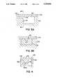
- FIG. 1is a vertical cross-section of a first embodiment of the invention showing a vent-assisted stop-flow junction.
- FIG. 2is a vertical cross-section of a second embodiment of the invention showing a stop-flow nozzle.
- FIG. 3Ais a vertical cross-section of a prior-art stop-flow junction showing a stop-flow junction formed at the junction of two separate housing members that have been welded together.
- FIG. 3Bis a vertical cross-section taken along line B--B of the embodiment shown in 3A.
- FIG. 4is a vertical cross-section of a further embodiment of the invention showing a through-body stop-flow junction of the invention.
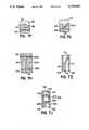
- FIG. 5is a vertical cross-section of still another embodiment of the invention showing a rupture junction in the capillary pathway that contains a stop-flow junction that is being stabilized.
- FIG. 6is a vertical cross-section of a diluter of the invention showing a stop-flow junction having the principal features of the stop-flow junction embodiments of FIGS. 1, 2, 4, and 5 along with other features of the diluter as a whole.
- FIGS. 7A through 7Jare a series of vertical cross-sections of the embodiment of FIG. 6 taken at locations A--A through J--J of the embodiment FIG. 6.
- FIG. 8in a schematic diagram of chemistry associated with a specific analysis that can be carried out in the embodiment of FIGS. 6 and 7.
- the present inventionprovides an improved stop-flow junction for use in apparatuses that require stoppage of capillary flow followed by controlled restart of flow.
- Such stop-flow junctionsare particularly useful in apparatuses and methods in which small samples are automatically measured and diluted.
- Such apparatusesare generally small, convenient to use, and require no moving parts for the movement of fluid, with gravity and capillary action being sufficient to provide all fluid motive forces required for the sample measurement and dilution steps.
- Such dilution and mixing cartridgesare described in U.S. Pat. No. 4,868,129, U.S. Pat. No. 5,077,017, and U.S. Pat. No. 5,104,813.
- the apparatuses of the present inventionprovide a number of improvements in stop-flow junctions relative to those described in previous dilution and mixing apparatuses, particularly in ease of manufacture and reliability of operation for large numbers of diluters made from the same mold.
- the specific improvement of the present apparatusare (1) means for selectively trapping a gas in a capillary passageway and non-capillary chamber adjacent to a stop-flow junction, wherein when said means for trapping is activated and a liquid enters said capillary passageway, said gas is compressed by said liquid as said liquid flows through said capillary channel and stops flowing at said stop-flow junction; (2) a stop-flow nozzle surrounding a capillary passageway and projecting into a chamber, with the stop-flow junction being at the entrance of the capillary passageway into the chamber; (3) a stop-flow junction formed from a single housing body member; and (4) a rupture junction in a capillary pathway, wherein said rupture junction is a stop-flow junction providing less maximum available back pressure than said capillar
- stop-flow junctionThe basic features of a stop-flow junction are described in the patents and patent applications identified above in the background section of this application.
- the junctionexists at the end of this region of free flow at a transition to a region at which capillary flow will cease, even in the presence of a gravitationally derived pressure arising from a liquid head above the capillary-stop junction.
- capillary junctionsexist in familiar devices, such as a capillary tube used for obtaining blood samples from a finger puncture.
- the stop-flow junctionis the end of the capillary tube, since capillary forces retain sample inside the tube, even when the tube is oriented vertically and gravitational forces are present on the sample.
- capillary forcesretain sample inside the tube, even when the tube is oriented vertically and gravitational forces are present on the sample.
- the first of the improvements that have been recognized and developed by the current inventorsis a technique (and associated apparatuses) in which a gas (usually air from the atmosphere surrounding the apparatus in which the stop-flow junction is located) is trapped and compressed when a liquid enters the capillary portion of the passageway and flows through the passageway to the stop-flow junction.
- the trappingmust be selective since the trapped gas will need to be vented in order for flow to continue unimpeded to other parts of the apparatus at an appropriate time.
- reliability of flow stoppage at the stop-flow junctioncan be increased many fold over. Since the volume of the trapped gas is manipulated most easily by changing the size of the vent channels and chambers, this aspect is referred to as a vent-assisted stop-flow junction.
- FIG. 1The operation of a vent-assisted capillary stop-flow junction is readily understood by reference to FIG. 1 and the mode of operation of the apparatus shown in the figure. However, it should be recognized that this is not the sole embodiment by which the present invention can operate and that the embodiment shown in FIG. 1 is merely exemplary of this aspect of the invention.
- FIG. 1is a vertical, cross-sectional schematic drawing of a dilution apparatus having a vent-assisted stop-flow junction.
- the diluter shown in FIG. 1is similar to the single-dilution apparatus described in U.S. Pat. No. 4,868,129 with the additional flow directing chamber of U.S. Pat. No. 5,104,813. Reference may be made to this earlier patent and patent application for detail on the various parts of the apparatus. The present discussion will address the vent-assisted stop-flow junction without prolonged discussion of other aspects of the device.
- Cartridge 100contains a sample application site 110, a capillary channel 120 leading from sample application site 110 to flow directing chamber 130, capillary measuring chamber 140, mixing chamber 150, capillary passageway 160 leading from flow directing chamber 130 to waste chamber 165, a rupturable container 175 of diluent in an internal chamber functioning as a diluent application site 170, and a channel 180 leading from the diluent application site to the flow directing chamber 130. All of these parts of the apparatus have been previously described in earlier patents and patent applications.
- Parts of the device relating specifically to the vent-assisted featureinclude an initial capillary channel 101 leading to a relatively large interior chamber 102 referred to as a vent-surge chamber, capillary channel 103 connecting vent-surge chamber 102 to the environment surrounding cartridge 100, where vent opening 104 exists to allow atmospheric gases to enter and leave venting channel 103 and other interior chambers of the device, and vent closure 105, which is capable of being moved in the directions shown by the arrow to alternatively close and open the vent at 104.
- vent closure 105Prior to application of a sample to sample application site 110, vent closure 105 is moved to the left where it seals against the housing at vent 104.
- the vent closuresubstantially seals the vent from the external environment. Any means that accomplishes this result is satisfactory, such as providing a flexible pad that presses against the surface of the housing at vent exit 104; providing a close-fitting, smooth disc that contacts a corresponding smooth surface on the housing; or any other effective means of sealing off the internal space in the housing from the surrounding atmosphere.
- the vent closureis typically operated by a monitor into which the housing has been inserted.
- sampleis applied at sample application site 110.
- Sampleflows through capillary 120 to flow directing chamber 130 and then into measuring chamber 140.
- the venting spacesconsist of capillary channels 101 and 103 and vent-surge tank 102.
- this vent-surge tankis included merely to provide an appropriate volume for the trapped air or other gas present in the indicated chambers and is therefore optional. If measuring chamber 140, mixing chamber 150, and the vent spaces leading to vent exit 104 provide the desired compressible volume of air, no vent-surge chamber 102 is required.
- the air trapped in the enclosed spaceis compressed. This compressed air will act to oppose the forward motion of the liquid in the measuring chamber and thus act to stabilize stop-flow junction 145 at the intersection of measuring chamber 140 and mixing chamber 150.
- vent closuresthat were designed to stop flow of sample in capillary passageways without requiring the concurrent presence of a stop-flow junction. Such vent closures were different from those used in the present invention.
- the build-up of pressure in the enclosed space in the present inventionis only sufficient to impede and partially counteract forward-directed pressure from the weight of the sample. If no stop-flow junction is present at a location where flow stoppage is desired and a vent closure is used in the manner described herein, forward-directed pressure would cause sample to continue to flow beyond the desired location.
- stop-flow junction 145is designed so that flow will occur at this location during the dilution step, maximum capillary force available at this junction is designed to be weaker then the head pressure at the stop junction for all cases in which diluent is present and vent 104 is open. This can be achieved simply by selecting an appropriate size for the opening at stop-flow junction 145.
- ⁇contact angle of sample on housing wall
- the head height availablecan be adjusted by appropriate design of the cartridge (e.g., a tall thin measuring chamber to maximize head height, or low-lying broad measuring chamber to minimize height).
- the contact anglecan likewise be used to control back pressure, either by selecting a material for manufacture of the housing (either the entire housing or a part thereof) that provides the appropriate contact angle or by modifying the surface properties of the housing at an appropriate location, e.g., by plasma etching, as has been described in earlier patents, such as U.S. Pat. No. 4,756,884.
- Empirical adjustment of head height and surface characteristic by appropriate design of the cartridgecan be used to control back pressure at a stop-flow junctions of any shape.
- vent-surge tank 102can be provided in different volumes, since this part of the apparatus does not affect the dilution that occurs in mixing chamber 150 (an additional stop-flow junction can be included in the early portion of the vent leading to the surge tank to keep the mixture from entering the surge tank).
- V 1pre-compression trapped-gas volume
- V 2post-compression trapped-gas volume
- V 2is the sum of the volume of the mixing chamber and the volume of the total vent space including the surge chamber.
- V 1is V 2 plus the volume of the measuring chamber.
- Other configurationswill result in compressions occurring in different parts of the apparatus, as shown in FIG. 6 below for a different embodiment.
- the formulas described abovewill not strictly apply.
- a different mode of operationcan allow proper functioning of a vent-assisted stop-flow junction without the indicated formulas being strictly adheared to.
- the momentum of diluent flowing from diluent application site 170can be used to overcome back pressure at the stop-flow junction even if the height of diluent and sample together are insufficient to start flow from an equilibrium state.
- the various techniques described in U.S. Pat. No. 4,868,129can be used to start flow rather than relying on the increased height of the column of sample and diluent.
- An additional feature that can be used to increase stability of the stop-flow junctionis to provide a nozzle surrounding the capillary portion of the stop-flow junction that projects into the non-capillary region (which can include projection into a recessed area in a chamber wall).
- the nozzleis shaped so as to provide exterior nozzle surfaces which form an acute angle with the adjacent surfaces of the interior wall of the capillary passageway.
- a typical projection with acute angles to prevent creep of liquids around the edges of the stop-flow junction and to increase the practical amount of available back pressureis shown in FIG. 2.
- FIG. 2is an expanded cross-section of the area surrounding stop-flow junction 145 shown in FIG. 1.
- Measuring chamber 140is visible along with the stop-flow junction 145 at the point where capillary chamber 140 enters non-capillary mixing chamber 150.
- Housing walls 141 surrounding the opening at 145project into chamber 150.
- Surface 142 of the wallforms an acute angle (represented by ⁇ ) with the adjacent interior wall of measuring chamber 140.
- the preferred shape for the nozzle formed by walls 141is a cone when stop-flow junction 145 is circular. However, there are no particular limitations on the shape of the nozzle as long as an acute angle is maintained.
- a cone recessed into a surface of a non-capillary chamberis preferred, as shown in FIGS. 7B-7D below, when liquid flow or other motion (such as of a mixing element) occurs in a chamber containing a stop-flow junction.
- stop-flow junctionscan be formed from a single housing body member rather than forming it at the junction of two members used to form a cavity. Such stop-flow junctions are referred to as through-body stop-flow junctions.
- FIGS. 3A and 3Bshow prior-art stop-flow junctions formed at an intersection between (1) a body member in which the various capillary and non-capillary chambers are formed as depressions on a surface and (2) a second body member that encloses the depressions in the surface of the first body member to form the interior chambers.
- capillary channel 140 and chamber 150are visible in body member 102, while body member 104, when sealed to body member 102, turns the depressions originally on the surface of body member 102 into internal chambers.
- FIG. 3Bwhich is a cross-sectional view taken along lines B--B of FIG. 3A
- joint 154 between body members 102 and 104intersects with the opening of capillary chamber 140 in wall 152 of chamber 150. If joint 154 is completely sealed, no problems arise. However, if during the manufacturing process, a gap is left at joint 154, capillary action will draw liquid in capillary chamber 140 into the crack and tend to defeat the purpose of stop-flow junction 145. Capillary "creep" will cause flow to occur at the edges of stop-flow junction 145, thereby allowing liquid to enter chamber 150.
- measuring chamber 140enters mixing chamber 150 not at a junction between two body members, but entirely within a single body member.
- a diluting apparatusis made up of three body members, namely a central body member 102 that contains various depressions such as 140a and 150 that will form capillary channels and non-capillary chambers when enclosed by additional body members 104 and 106.
- measuring chamber 140comprises two segments 140a and 140b. Segment 140b is formed in an injection molding process using a pin that passes through the mold used to prepare body member 102.
- Diluters that operate using stop-flow junctions of the inventioncan be prepared using multiple stop-flow junctions in which one of the junctions is sacrificial; i.e., it is designed to fail before other junctions in order to protect the operation of the other junctions.
- a sacrificial junctionis referred to as a rupture junction in this specification.
- stop-flow junctions of the inventioncontain valves that are operated by the application of an external force to the valve (see U.S. Pat. No. 5,077,017).
- valves in a dilutercauses pressure waves to travel through the fluid contained in various passageways in the device. These pressure waves can cause the failure of a stop-flow junction.
- a rupture junctiondesigned to fail at a pressure lower than the maximum back pressure that is available at other stop-flow junctions in the same capillary passageway, relief for the pressure wave is provided in a manner that will not adversely affect the operation of the diluter or other apparatus.
- a capillary passagewaycan be provided containing a valve in some portion of the passageway.
- a rupture junctioni.e., a stop-flow junction with a lower maximum back pressure
- the maximum back pressure available at the rupture junctionwill be at least 10% less than the back pressure available at the next weakest stop-flow junction in the passageway, more preferably at least 20% less.
- Diluter 100contains an application site 110, a capillary passageway 120 leading from sample application site 110 to measuring chamber 140 comprising segments 140a and 140b. Segment 140a terminates at stop-flow junction 146 where the segment meets diluent application site 170 while segment 140b terminates at stop-flow junction 145 at the entrance to chamber 150. Vent 101 and vent closing means 105 are present as in FIG. 1.
- a valveis present in the capillary passageway leading to measuring chamber 140, which consists of flexible wall member 201 and plunger 202, which is external to the device 100 and which operates to force flexible wall member 201 against the opposing wall to block passage of fluid.
- a rupture junctionis present at 147 in capillary passage 120 leading to measuring chamber 140. Rupture junction 147 leads into rupture chamber 148 (for containing excess liquid) which is vented by vent channel 149.
- sample applied to sample application site 110flows through capillary channel 120 and fills all of the capillary spaces between the application site itself and stop-flow junctions 145, 146, and 147 (the last being the rupture junction).
- stop-flow junction (rupture junction) 147is designed to fail before either stop-flow junction 145 or stop-flow junction 146, the pressure waves generated by closing the valve is relieved by flow of excess sample into rupture tank 148.
- rupture junctionhas been described with regard to a particular embodiment shown in FIG. 5, other embodiments will be readily apparent to those skilled in the art.
- Rupture junctionscan be designed into any apparatus in which temporary halt of flow is desired after which events occur that are not intended to, but which may accidentally, cause flow to occur at stop-flow junctions, such as the opening and closing of various valves.
- stop-flow junctionssuch as the opening and closing of various valves.
- the cartridges of the present inventionincludes a sample application site, a diluent application site, a measuring chamber, a mixing (receiving) chamber, various channels to provide flow of liquid between parts, and, in the case of serial diluters, a mixture isolating and measuring chamber and at least one valve controlling passage of fluid from the mixing chamber to the mixture isolating and measuring chamber. All of these parts of the cartridges have been described in the indicated applications, which can be referred to for greater detail.
- the apparatus of the inventioncan provide for a single dilution, as in the valveless diluters described in U.S. Pat. No. 4,868,129.
- Serial dilutionscan be provided for using a valve to control passage of a portion of the initially obtained mixture into a mixture isolating and measuring chamber.
- This mixture isolating chambercan take any of the forms described in U.S. Pat. No. 5,077,017.
- the mixture isolating chambercontains essentially the same chambers and passageways as the initial diluting pathway described above. All of these parts are described in greater detail below. The following detailed description of the various parts of the apparatus is organized by following the course of action as a sample is applied to the apparatus and is diluted.
- the sampleis a liquid and may be derived from any source, such as a physiological fluid; e.g., whole blood, blood plasma, blood serum, saliva, ocular lens fluid, cerebral spinal fluid, pus, sweat, exudate, urine, milk, or the like.
- the liquid samplemay be subjected to prior treatment such as preparing serum or plasma from blood or dissolving or suspending a solid in a liquid.
- sample treatments prior to application to the apparatus of the inventioninclude concentration, filtration, distillation, dialysis, inactivation of natural components, chromatography, and addition of reagents.
- other liquid samplescan be employed. Examples of other liquid samples include process streams, water, plant fluids, chemical reaction media, biological growth media, and the like.
- the liquidwill be aqueous, although other liquids can be employed.
- Aqueous mediamay contain additional miscible liquids, particularly oxygenated organic solvents, such as lower alkanols, dimethyl formamide, dimethyl sulfoxide, acetone, and the like.
- oxygenated organic solventssuch as lower alkanols, dimethyl formamide, dimethyl sulfoxide, acetone, and the like.
- the solventswill be present in less than about 40 vol %, more usually in less than about 20 vol %, in order to maintain the high surface tension that is present in aqueous solutions.
- the apparatus of the inventioncan be modified as described below for use with liquids exhibiting different surface tensions.
- the apparatus as described initially hereinprovides for a single dilution of a sample with a diluent. Any apparatus that carries out a dilution in the manner described is considered to fall within the scope of the present invention, whether the dilution occurs by itself or as part of additional operations that occur in the device. For example, other operations can be carried out on an original sample so as to provide a mixture. This mixture is then the "sample” that is later diluted. Alternatively, provision can be made for other operations to take place on the mixture formed in the manner described above.
- the sample application site(also referred to as a sample receiving site) will generally be a cavity on a surface of the apparatus or may simply be an opening (optionally surrounded by a ring or tube) leading to the interior of the apparatus.
- the sample application sitecan contain a filter, for example, to separate red blood cells from plasma (see U.S. Pat. No. 4,753,776), or may represent a connection between the apparatus of the invention and some other apparatus that manipulates the sample prior to its entering the present dilution apparatus.
- the application sitecan be a recess into which a standard capillary tube will fit.
- the capillary tubecan act either as a convenient means for transferring the sample or can act as a measuring chamber, either by completely filling the capillary or by filling the capillary to a particular mark.
- the sample application sitein such embodiments acts as a point of transfer.
- the sample application sitewill be an external chamber, such as a recess on an upper surface of the device into which sample is inserted.
- Such surface recessesare referred to herein as external chambers, to distinguish them from chambers located in the interior of the housing that forms the cartridge.
- the application sitecan be provided with a raised lip surrounded by a catch basin so that the application site can be filled to overflowing with excess sample overflowing into the catch basin. Means for draining off a large excess of sample or sample inadvertently applied to the wrong location are discussed in U.S. Pat. Nos. 4,868,129 and 5,077,017, discussed above.
- the liquid sampleWhen sample is applied to the sample application site, the liquid sample normally flows without the application of external force (except unassisted gravity) through a fluid passageway into a measuring chamber in the interior of the device.
- external forceexcept unassisted gravity
- the samplecan flow directly into a measuring chamber.
- the sampleit is also possible for the sample to flow into a flow directing chamber, comprising an internal chamber in the housing that forms the apparats before entering a measuring chamber, as described in U.S. Pat. No. 5,104,813.
- External forcee.g., from compressed air, can be used to move the sample to the measuring or flow directing chamber but is not required and in fact is not preferred.
- the flow directing chamberacts to divert a portion of the sample that first enters the flow directing chamber into the sample measuring chamber, which has a predetermined volume and which operates to measure and hold a portion of the sample for dilution.
- the remainder of the sample that enters the flow directing chamberis automatically diverted by the flow directing chamber into an exit port leading to a waste chamber or to some other means of disposing of excess sample beyond that required to fill the sample measuring chamber.
- the measuring chambercan be a capillary channel or chamber, in which case capillary action will aid or in some cases provide all the force necessary for filling the measuring chamber with sample from the sample application site by way of the flow directing chamber.
- Capillary channels and chamberswill generally have at least one dimension perpendicular to the flowpath in the range of 0.01 to 2.0 mm, more generally 0.1 to 1.0 mm.
- Capillary spaces(of whatever type) have at least one dimension at right angles to the direction of flow in the range required to support capillary flow.
- Capillary channelshave both dimensions at right angles to the direction of flow in the range required to support flow.
- Capillary chambershave one dimension at right angles to flow that would not support capillary flow but provide for capillary flow by having the second dimension at right angles to flow in the required range (similar to the space between two flat plates that are closely spaced). However, larger measuring chambers that are not capillary in any dimension are also possible.
- the sample measuring siteis said to be in " fluid receiving relationship" to the previous capillary passageways in order to indicate that unassisted flow into the measuring chamber occurs. In order for proper operation of the stop-flow junction to occur, it is essential that the measuring chamber be filed solely by capillary and gravitational forces, as will be apparent from the description of the stop-flow junction below.
- the geometry of the measuring chamberis such that, when diluent is added to the apparatus at a later dilution step after measurement is completed, essentially all of the sample in the measuring chamber will be expelled into the mixing chamber.
- One means of accomplishing thisis by providing for smooth flow of diluent through the measuring chamber.
- a straight or curved tube with an essentially constant cross section open at both endsis thus a preferred embodiment for this type of measuring chamber.
- This type of measuring chamberis seen in measuring chamber 140 of FIG. 1.
- diluententers the measuring chamber in a front across the entire cross-sectional area of flow.
- measuring chambersthat vary in cross section are also possible, as discussed in prior applications. Nevertheless, it is desirable to have the initial portion of the measuring chamber be as small as practical, as this aids in reducing the amount of sample that may be lost from the measuring chamber when diluent initially rushes into the flow directing chamber. Initial diameters of less than 0.5 mm are desirable, preferably less than 0.2 mm. If the entrance to the sample measuring chamber is large, sample can be washed up into other passageways or chambers when diluent first enters. An unmeasured quantity of sample then flows, e.g., into a waste chamber as diluent continues to fill a flow directing chamber and then flow into both the measuring chamber and the waste chamber. Although this problem cannot be completely eliminated, using a small opening to the sample measuring chamber will reduce sample losses to acceptable levels. A small opening is therefore preferred even when the remainder of the measuring chamber is large (e.g., of non-capillary dimensions).
- measuring chambersWhile most measuring chambers will be manufactured to have a fixed volume, it is possible to provide chambers (both measuring chambers and other types of chambers and internal compartments) whose volume can be varied, for example by a closely fitting plunger used to adjust the volume of the chamber prior to use.
- the internal volume of such an adjustable chamberwould be set to the desired value by the user, normally prior to addition of sample to the apparatus.
- diluent application sitesare disclosed in U.S. Pat. No. 4,868,129 and U.S. Pat. No. 5,077,017, discussed above. Any of these diluent application sites can be used in an apparatus of the present invention if desired.
- the diluent application siteis an internal vented chamber in the housing that forms the apparatus. Located in the chamber is a rupturable container of diluent. Glass containers are particularly preferred, although frangible plastic can also be used. An access port may be provided so that externally applied pressure can be used to rupture the container.
- a frangible glass or plastic container located within the housingcan be broken by a sharp blow to the housing itself. If the frangible container is sized for its chamber so that deformation of the chamber walls (i.e., wall of the housing surrounding the frangible diluent container) allow the motive force of the blow to also strike the frangible container, then the frangible container will break without requiring an access hole to the chamber. This represents an improvement over prior embodiments of the diluter, as leakage of diluent from the cartridge after use is eliminated.
- a flexible areacan be provided on the wall of the chamber surrounding the diluent container, such as by providing a thin housing in a target region at that location. Providing a thinner and more flexible housing will increase the possible deformation upon receipt of a blow. The central point of the target region can be thicker than the surrounding flexible region in order to better absorb the energy of the blow without breaking.
- Exact dimensionsare best determined emperically for a given diluent container, chamber, and housing material.
- an ABS housingwith a wall thickness of 0.020 inch, a target region thickness of 0.015 inch, and an ampule chamber 0.275 inch thick containing glass ampules ranging in thickness from 0.258 to 0.272 inch, worked well.
- a passagewayconnects the diluent chamber to the flow directing chamber or measuring chamber.
- Diluentflows into the measuring chamber so that the hydrostatic pressure at the stop-flow junction is exceeded and the sample is expelled into the receiving chamber along with a portion of the diluent. Excess diluent flows into a waste chamber in some embodiments or remains in the diluent application chamber and/or flow directing chamber.
- vents used in the various chambers of the devicecan merely be a small hole terminated by a stop-flow junction in order to avoid exit of liquid from the device or can be a more sophisticated vent designed for gas exit without exit of liquid (e.g., a microporous, hydrophobic plug capable of passing air but not hydrophilic liquids).
- Stop-flow junctionscan also be placed in the early portion of a long vent to prevent a relatively large quantity of liquid from entering the vent from the vented chamber.
- a vent or other means to allow exit of trapped airis provided at every location in the apparatus in which the trapping of air would interfere with the passage of liquids between the various chambers and/or channels of the device. If desired vents can be selectively opened and closed, as described for vent-assisted stop-flow junctions.
- ventsA preferred manner of forming vents is to use interior waste space in the housing as vent space to catch any liquids that may accidently be forced through a vent channel.
- the initial venting channel leading from, for example, a mixing chamber to the waste spaceis then essentially an internal venting space, with an external vent at a location in the waste space that is unlikely to be reached by liquid which can function as the final external vent.
- this internal/external venting systemcan also provide the surge tank arrangement already discussed for vent-assisted stop-flow junctions, in addition to providing the additional safety function of trapping potentially dangerous samples or reagents inside the housing (which can be disposable).
- the method and apparatusare particularly suitable for measuring and diluting small quantities of liquids.
- the sample measuring chamberwill generally have a volume of from 0.1 ⁇ L to 10 ⁇ L, preferably 1 ⁇ L to 30 ⁇ L, and most preferably 3 ⁇ L to 10 ⁇ L.
- the receiving chamberwhich acts to limit diluent volume and fix the ratio of sample to diluent, generally has a volume of from 3 ⁇ L to 1000 ⁇ L, preferably 10 ⁇ L to 300 ⁇ L, and most preferably 30 ⁇ L to 200 ⁇ L, thereby providing dilution ratios of from 10 4 :1 to 3:1, preferably 10 3 :1 to 4:1, and most preferably 100:1 to 5:1.
- Channels through which capillary flow will take placewill usually have opposing walls spaced in the range of about 0.01 mm to 2 mm, more usually about 0.1 mm to 1 mm.
- the capillary spacescan be tubular (which does not necessarily imply a circular crosssection but can be square or other regular shapes) or can represent the spaced formed by flat plates and side walls with the side walls being spaced further apart than a capillary distance.
- a tubular chamber with at least one flat sidee.g., a square cross-sectional area, a rectangle with adjacent sides differing in length by no more than a factor of 1:2 to 1:4, or a semicircular chamber
- channelsare being formed by the joining of two adjacent surfaces, one of which can be flat.
- valvesthat will control the passage of liquids between chambers and/or channels can be used in the apparatus of the present invention.
- Simple valvesthat can be actuated to move between an open and a closed position by the application and release of a simple external force are preferred.
- valvesinclude resilient blocking members that are present in or adjacent to a liquid flowpath.
- a resilient blocking membercan be present in a converging or diverging pathway so that the narrow portion of the pathway is blocked by the resilient blocking member when the blocking member is in its normal position.
- Application of force in a direction generally away from the restricted portion of the flowpath and toward the wider portion of the flowpathwill open the valve by moving the blocking member away from the narrow walls of the flowpath.
- a normally open valvecan be provided which is blocked by movement of a resilient blocking member to a location that cuts off flow of liquid. Specific examples of such valves are set forth in more detail below.
- valvesinclude sliding pins closely engaging a channel that laterally traverses a fluid flowpath.
- the pinhas a segment capable of obstructing flow through the flowpath when the pin is in a first position and a segment capable of allowing flow through the flowpath when the pin is in a second position.
- Examples of such pinsinclude rectangular pins having a flowpath channel between two opposite faces of the pin, the flowpath channel being out of register when the block is in a closed position and in register with the principal flowpath when the block valve is open.
- Pins with circular cross-sectionscan be used by providing an obstructing segment of the pin that snugly engages the channel in which the pin fits and obstructs the flowpath when the pin is in a closed position.
- a smaller cross-sectional area(such as is present in the handle of a dumbbell) provides an annular flowpath around the smaller, central portion of the pin when the pin valve is in the open position.
- a resilient membercan be provided to bias the pin into either the closed or the open position. A force acting on the pin can then slide the pin to a second location so that the pin valve is in the alternate position.
- access for the application of an external force on the pinis provided so that the pin can be moved between its two positions.
- a section of the pin that protrudes externally from the apparatuscan be provided so that a force acting parallel to the sliding axis of the pin can move the pin from its first biased position to a second position by acting against the direction of the biasing force.
- an aperture leading from a face of the pin opposite the biasing force to the external environmentcan be provided.
- Externally applied pressuresuch as from compressed air or a finger of an external apparatus that enters the aperture, can be used to slide the pin between its open and closed positions.
- a resilient sealcan be provided to prevent loss of liquid through the aperture while allowing force to be applied to the pin. Such seals can also be provided for the resilient blocking members described above.
- valves that can be used as integral parts of a cartridge of the present inventionare not limited to those specifically exemplified here. Rather, any valve can be used that can control the flow of liquids through small flowpaths, such as flexible walls (e.g., latex) of a flowpath that can be compressed to restrict flow of liquid through the flowpath. Additionally, a dissolvable barrier can be provided in instances where an initially closed valve will be opened once and then maintained in the open position.
- a flowpath through which capillary flow occurscan be blocked by closing an external vent.
- the external ventWhen the external vent is closed, liquid cannot enter the capillary pathway because of air or other gases in the capillary pathway. Opening the vent allows liquid to enter the capillary pathway. If the vent is closed while liquid is contained in the capillary pathway, the isolated liquid can later be used for other manipulations.
- Valves consisting of external vent controlscan be used in any situation where flow occurs through a capillary pathway (so that trapped air is effective to control flow of liquids) and where no free liquid that might leak is stored in the cartridge prior to use.
- Encapsulated liquide.g., in glass ampules
- Internal mechanical valves or rupturable barriersare preferred for such uses in order to prevent accidental leakage.
- a cartridge-like deviceBy providing valves that can be operated by a simple externally applied force, a cartridge-like device can be provided in which the valves are opened and closed in a predetermined manner by an analytical device into which the cartridge is inserted.
- This analytical devicecan contain various optical and/or other types of sensors for detecting the presence of liquids or analytes in various mixing and/or measuring chambers of the cartridge in addition to providing means for opening and closing the valves and is therefore sometimes referred to in this specification as a monitor.
- the apparatus of the present inventioncan be designed for use with a particular assay or can be designed and prepared as an apparatus in which multiple assays can be carried out, depending on the order in which various valves are opened and closed and the contents of the various diluents, which can contain reagents for the development of a detectable signal (e.g., a color reaction) that depends on the presence of an analyte in the sample.
- a detectable signale.g., a color reaction
- Reagentscan be provided at various locations in the device. Incubation times can be controlled by either manual operation of valves or by a mechanically or electronically stored program in the monitor into which the cartridge is inserted.
- the programwould control the order and timing of opening and closing valves.
- the programmed devicewould contain solenoids or other means for providing force to open and/or close valves or rupture containers containing diluent.
- a movable sealing padthat is capable of closing the vent will form part of the external programmed device into which the cartridge is inserted.
- the apparatus shown in the Figures and otherwise described hereinwill normally be inserted into an apparatus in which analytical measurements on the sample can made.
- the analytical instrumentis sometimes referred to as a monitor.
- Optical measurementsare common and are the preferred type of measurement for use in monitors.
- a light source and a detectorare located in the monitor so that the light impinges on the desired location in the mixing and dilution chamber, passes through the chamber and the material enclosed therein, and impinges on the detector located at the other side of the cartridge. This is accomplished by inserting the cartridge into a chamber of the monitor so that all of the parts are placed into proper registration with each other.
- the present inventionrequires nothing new in the way of light sources, detectors, and registration means, since all spectrophotometers that engage cuvettes and carry out light measurements there through provide the necessary detection and registration systems.
- the monitorcan provide additional light sources and detectors to detect the presence of the fluid at various points in the fluid pathways throughout the cartridge.
- such componentsare called system control components since they represent a means by which the monitor can verify whether sample, the diluted mixture, or the like have reached the proper points in the fluid pathway in the proper sequence and at the proper time.
- light sources and detectorscan be placed at opposite sides of the cartridge so that the detector measures light passing through the sample in passageway 120 at optical window 122 to determine when sample has been applied to the cartridge (see FIG. 6).
- Various operations of the cartridgecan be automatically provided by detecting presence of absence of various liquids in the cartridge, as has been described in previously listed applications and patents.
- the monitoris generally designed to be capable of detecting correct operation of the cartridge by providing sensors that detect the presence of liquids at numerous locations in the fluid pathways of the cartridge and comparing the signals provided by the sensors with the signals that would be produced during proper operation of the cartridge. Automatic detection of proper operation is desirable when the cartridge is in the hands of an unskilled user, which is a desired end use of the cartridge. For example, if the user must apply a drop of blood (as the sample) to the sample application site, several problems can occur. Some patients have trouble obtaining a drop of blood of sufficient volume. For example, if proper operation of the cartridge requires 25 ⁇ l of blood and only 20 ⁇ L is added to the sample application site, the sample measuring site may not completely fill. If diluent is then added automatically (such as after a preselected time), the dilution will be greater than desired, and an incorrect result will be obtained.
- the cartridges of the inventionare typically prepared from molded plastic as described in U.S. Pat. No. 4,756,844, the only principal differences between the production methods described in the patent and the production required for the present apparatus being in the mold used to form the various chambers.
- plasma etchingcan be used to improve flow characteristics through the various capillary pathways, since most molding plastics are hydrophobic and need to be rendered hydrophilic for reproducible capillary flow to occur.
- the present inventorscontemplate providing serial dilution and mixing capabilities using a mixture measuring and isolating chamber hydrostatically connected to the mixing chamber and a valve controlling passage of fluids from the mixing chamber to the mixture isolating chamber.
- the first dilutiontakes place as indicated above during which time the valve is closed to prevent escape of liquid from the mixing chamber.
- the valve controlling flow to the mixture isolating and measuring chamberis opened, and fluid flows from the mixing chamber under the influence of hydrostatic pressure and/or capillary attraction.
- the portion of the mixture isolating chamber into which the mixture flowsis smaller in volume than the total volume of mixed sample and diluent.
- This volumeis determined by the geometry of the chamber, the amount of hydrostatic pressure available from liquid in the mixing chamber, and any capillary forces that are present.
- U.S. Pat. No. 5,077,017, described abovedescribes various geometries that can be provided for a mixture isolating chamber depending on whether the intent is to carry out a second dilution in the original mixing chamber of to transport the isolated portion of the mixed sample and diluent to another location for further dilution and/or analysis. Any apparatus that carries out a single dilution as described above and a second dilution as described in the prior application will fall within the scope of the present invention.
- the mixture isolating chamberwill comprise the same types of chambers and passageways as described previously, with the exception that they will operate on the mixture as a sample rather than on an initially obtained sample.
- FIG. 6is a plan view from the front of a first embodiment of the invention in which lines A--A, D--D, etc., show the location of the corresponding cross-sectional views shown in FIGS. 7A, 7D, etc.
- housing 100is prepared from three separate pieces, a central base member 102 and two cover plates 104 and 106. Chambers formed in the front face of base member 102 are shown with solid lines in FIG. 6. Passageways formed in the back face of base member 102 are shown by dashed lines in FIG. 6. Through connections, which are generally holes passing from one face to the other, are shown by circles in FIG. 6. All such passageways would be visible in embodiments prepared from transparent plastic, as described in U.S. Pat. No. 4,756,844. However it is also possible to prepare the cartridge from an opaque material if provisions are made for light paths at the appropriate locations.
- the apparatus shown in FIG. 6is capable of carrying out two dilutions serially. Parts of the apparatus associated with the first dilution are numbered from 110 to 182. Parts of the apparatus associated with the second dilution are numbered from 205 to 282. Where two parts perform the same function in the first and second dilutions, the last two digits of the identifying number are the same. Parts of the apparatus associated with the housing are numbered from 100-106. The apparatus will be described by reference to the indicated numbers while following a sample through a series of two dilutions in the apparatus.
- a sampleis added initially to sample application site 110.
- the sampleflows down capillary passageway 120 to measuring chamber 140.
- Passageway 120consists of an initial segment 120a connecting diluent application site 110 to the remainder of the passageway, a segment 120b (leading to a rupture junction 147 shown in FIG. 7I), and a segment 120c containing valve 125 that is connected at one end to both segment 120a and 120b and at the other end to measuring chamber 140.
- Segment 120bterminates in rupture chamber 130, which has a venting exit 132 and venting channel 133 leading to internal vent 134.
- Measuring chamber 140consists of vertical segment 140a terminating at stop-flow junction 146 and horizontal segments 140b and 140c (the latter terminating at stop-flow junction 145 as shown in FIG. 7B). Sample flow stops when the leading edge of the sample reaches the various stop-flow junctions 145-147. Vent channel 152, located in a upper portion of dilution and mixing chamber 150, is connected to vent surge tank 154 and eventually to vent opening 156 by channel 153 to allow controlled exit of gases from chamber 150.
- Frangible container 175is (not visible in this view) provided in an internal chamber 170 that functions as the diluent application site. Chamber 170 is connected by internal passageway 180 to measuring chamber 140 at stop-flow junction 146. Passageway 180 is vented to atmosphere via a vent channel 182 leading to an internal vent 182.
- Mixing in chamber 150can be provided by a number of techniques, such as are described in U.S. Pat. No. 5,028,142. It is possible to begin mixing the sample and diluent as they enter the chamber so that any mixture entering the vent will have approximately the same composition as the mixture remaining in the chamber. Better is to allow undisturbed filling of the chamber. In either event, the volume of the vent is sufficiently small so that negligible error results. Additionally, it is possible to include a separate stop-flow junction in the vent channel to prevent excess exit of liquid, should higher accuracy be desired. Such a stop-flow junction in the vent channel exiting the mixing chamber is shown below in FIG. 7G.
- Exit 210 in receiving chamber 150serves as the entrance for mixture into the second dilution portion of the apparatus.
- passageway 220is blocked by valve 225, and trapped air prevents mixture from entering the passageway.
- the valveWhen the valve is open, a portion of the mixture flows through exit 210 and channel 220 to a second measurement chamber 240, referred to herein as the mixture measurement chamber, which, as for measurement chamber 140, consists of a vertical segment 240a and horizontal segments 240b and 240c.
- Mixture measurement chamber 240terminates at stop-flow junction 245 where chamber 240 intersects with mixture diluting chamber 250 and at stop-flow junction 246 at the diluent end of the measurement chamber.
- Second diluentis provided in rupturable diluent container 275 (not visible in this view) contained in diluent chamber 270.
- Diluentbecomes available at diluent application site 270 upon rupture of the container, flows into channel 280, and enters mixture measurement chamber 240 at stop-flow junction 246.
- Channel 280is vented at vent 282.
- the hydrostatic pressure provided by the diluentis available to overcome the back pressure at stop-flow junction 245.
- Diluentflows through mixture measuring chamber 240 into mixture receiver chamber 250, expelling trapped air through vent exit 252 and channel 253 leading to surge chamber 254.
- Surge chamber 254is provided to give the volume necessary for proper operation, as described above. Mixing takes place in mixing chamber 250 in the same manner as in mixing chamber 150.
- FIGS. 7A through 7Jshow a series of cross-sectional views at different locations of the embodiment shown in FIG. 6.
- the apparatusis assembled by attaching cover plates 104 and 106 to central body member 102 in which the various chambers and passageways are formed.
- FIGS. 7A-7Hthe top sides of the figure represents the back face of the embodiment shown in FIG. 6 and the bottom side represents the front face except when indicated otherwise.
- FIG. 7Ais a sectional view of the embodiment shown in FIG. 6 taken along lines A--A, with the back of the embodiment of FIG. 6 appearing at the top of FIG. 7A.
- the three body members that make up housing 100are visible in this figure.
- a central body member 102has various depressions in its upper and lower surfaces (as viewed) along with through passageways from one surface to the other.
- Front (104) and back (106) face platesare sealed to the central body member 102 to form the internal cavaties that make up the capillary and non-capillary chambers and passages of the diluter.
- cavity 105plays no part in the operation of the diluter but is an internal cavity that prevents the central body member 102 from being unduely thick, thereby reducing time spent during molding operations.
- Rupture tank 130is next visible along with segment 120b of capillary passageway 120 and the rupture junction 147 at the intersection of passageway 120c and chamber 130.
- Passageway segment 120bis visible along the front face of body member 102.
- Initial segment 120a of passageway 120(not visible in this view; see FIG. 6) joins the remainder of the passageway at the common junction between segments 120b and 120c.
- section 120c, 120d, 120e, 120f, and 120g of capillary passageway 120along with valve 125.
- Segment 120cis formed by a depression in the front face of body member 102 that is covered by face plate 106.
- Sebment 120dis a through passage between segment 120c and the depression that forms the loction of valve 125.
- Valve 125operates by application of external pressure to flexible covering 127, which blocks passage of fluid when forced into depression 125.
- Depression 125is connected to depression 120e in the back face of central body member 102, and from there to through passageway 120f that connects to the last segment of passageway 120, a depression 120g in the front face of body member 102.
- Segment 120gis connected to horizontal measuring segment 140b at a location about midway between through passageway 120f and through passageway 140c, which terminates at stop-flow junction 145 in mixing chamber 150.
- Vertical measuring segment 140a(not visible in this view; see FIG. 6) also is connected to segment 120g and segment 140b at their common junction.
- Passageway 220which leads from mixing chamber 150 to measuring chamber 240, consists of segments 220a-220h and valve depression 225. These passageway segments function in essentially the same manner as the various segments of passageway 120. Measuring chamber 240a (not visible; see FIG. 6) and 240b both join with the far end of segment 220h. Measuring segment 240b leads to through passageway 240c, which terminates in stop-flow junction 245 at the entrance to chamber 250.
- FIGS. 7B through 7Hare expanded sectional views of different stop-flow junctions of the diluter embodiment of FIGS. 6 and 7A.
- FIG. 7Btaken along line B--B of FIG. 7B, is capillary stop-flow junction 145 in chamber 150.
- Through passageway 140cterminates in nozzle 141 located in a recessed area 142 of wall 143 of chamber 150.
- FIG. 7Ctaken along line C--C of FIG. 7A, shows capillary stop-flow junction 245 in chamber 250.
- Through passageway 240cterminates in nozzle 241 located in recess 242 of wall 243 of chamber 250.
- FIG. 7Dtaken along line D--D of FIG. 6.
- Through passageway 140aterminates in nozzle 181 located in recess 182 of wall 183 of chamber 180.
- FIG. 7Etaken along line E--E of FIG. 7A, shows rupture junction 146 in rupture chamber 130.
- Through passageway 120bterminates in nozzle 131 located in wall 133 of chamber 130.
- FIGS. 7D, 7B, and 7Eshow an upper capillary stop-flow junction 146 that is designed never to break, a lower capillary stop-flow junction 145 that is designed to hold initially and then break when diluent is applied, and a rupture junction 147 that is designed to break before either of the other two.
- the scale drawingsshow a small diameter for upper stop-flow junction 147 (FIG. 7D), an intermediate diameter for lower stop-flow junction 145 (7B), and a large diameter for rupture junction 146 (7E).
- Stop-flow junctions of the inventionare also present at other locations.
- FIG. 7Ftaken along line F--F of FIG. 6, shows vent 182 terminating in an interior waste space 186.
- a nozzle 181is present to increase back pressure.
- FIG. 7Gtaken along line G--G of FIG. 6, shows a stop-flow junction 152 in the initial through passageway 153a of vent channel 153 at the exit of mixing chamber 150.
- a similar stop-flow junction 252is present in vent channel 253 at the exit of mixing chamber 250 (not shown in detail; see FIG. 6).
- Additional stop-flow junctionscan be provided at locations in vent channels more distant from the mixing (or other liquid-containing) chamber for additional leakage protection, such as at through passageway 256 of vent channel 253.
- FIG. 7Htaken along line H--H of FIG. 6, shows this through passageway in detail.
- Through passageway 253btraverses body member 102 from the initial portion 253a of vent channel 253 on the back face of body member 102 to the later portion 253c on the front face.
- a stop-flow nozzle 251is visible at the location where passageway 253b enters channel 253c.
- FIG. 7Iis a sectional view of the sample application site 110 taken along line I--I of FIG. 6 showing sample application cavity 110 and an initial section of capillary passageway 120 along with interior waste chamber 112.
- FIG. 7Jis a sectional view of the diluent application chamber 270 taken along line J--J of FIG. 6 showing diluent application site (chamber) 270, an initial portion of diluent channel 280, and a portion of surge tank 254. Diluent container 275 is visible in chamber 270.
- a pin 103 in body member 102 that fits into a hole 107 of body member 106 in order to insure proper registration of body members 102 and 106 during manufactureis also visible.
- a flexible target region 277 with a a thicker central target point 278, which is struck by an external blow in order to break container 275,is also visible in this view.
- FIGS. 6 and 7The entire apparatus shown in FIGS. 6 and 7 would be approximately 5 cm high and less than 8 cm wide with body member 102 being about 0.7 cm in thickness.
- the cartridgecan readily be prepared in other sizes to carry out other analytical measurements.
- a sample of unknown volumeis applied to the sample application site 110.
- rupture tank vent 134is opened to atmosphere by the monitor.
- control valve 125As soon as rupture tank vent 134 is opened to atmosphere, control valve 125 is closed by the monitor. Since rupture junction 147 is designed to provide the least resistance to flow along the sample flow path, any shock that is created by closing control valve 125 is dissipated by sample flowing into rupture tank 130. This maintains the position of the sample at upper stop-flow junction 146 and lower stop-flow junction 145.
- By closing control valve 125the portion of sample filling the capillary passageway at segments 140a, 140b, and 140c is isolated from the rest of the sample, which will remain in the various parts of passageway 120 during remaining operations, including the portion of passageway 120 to the right of valve 125 but to the left of the junction of passageways 140a and 140b.
- the isolated portion in measuring chamber 140is a precise portion of the original sample.
- diluent ampule 175is broken by a blow on target point 278 (provided by the monitor), and diluent flows through the diluent application site 170 into channel 180 and fills channel 180 to and including vent 182.
- mixing chamber 150Once mixing chamber 150 has been completely filled, a mixing ball (not shown) in chamber 150 is reciprocated, mixing the diluent and sample, thereby completing the first dilution sequence.
- control valve 225is opened by the monitor, allowing a portion of the mixture from mixing chamber 150 to flow into the rest of the cartridge.
- Samplei.e., the first mixture flows through passageway 220 and valve 225 and into the upper arm 240a and lower arms 240b and 240c of the mixture measuring passageway 240. Flow stops at upper stop-flow junction 246 and lower stop-flow junction 245. Sample does not break lower stop-flow junction 245 and flow into the the second mixing chamber (250) since vent 256 is closed by the monitor and surge tank 254 is not vented to atmosphere.
- control valve 225Shortly after sample is detected by the monitor at upper stop-flow junction 245, control valve 225 is closed. By closing this valve the portion of diluted sample (from the first dilution) filling measuring segments 240a, 240b, and 240c is isolated from the rest of the sample. The isolated portion is a precise portion of the mixture from dilution and mixing chamber 150.
- mixing chamber 250, vent channel 253, and surge tank 254are opened to atmosphere by opening vent 256.
- the diluent ampule 275is broken, and diluent flows through diluent application site 270 and diluent channel 280, filling these chambers to vent 282.
- FIG. 8is a schematic diagram showing reagents that could be used with a cartridge of the type as shown in FIGS. 6 and 7 to carry out a specific diagnosis.
- a therapeutic drugsuch as theophylline
- the assayuses whole blood as the sample.
- red cells and other "formed elements"are dissolved by dilution into a medium containing detergent.
- the assay system(monitor and reagent-containing cartridge) accomplishes this dissolution by a combined dilution/mixing step (the first dilution) and then performs a second dilution/mixing operation to combine diluted sample with two initially dry reagents that are dissolved and resuspended by mechanical mixing.
- One of the reagentsis a dispersion of latex particles which agglutinate at a rate inversely related to drug concentration in the sample.
- the assay reactionis measured by following the increase of turbidity in the reaction medium over about 20 seconds.
- a sample from an unmeasured blood dropwill be applied to sample application site 110.
- Samplewill flow into measuring chamber 140 through passageway 120.
- a detergent solutionwhich also contains excess ferricyanide and azide, will flow through measuring chamber 140 into mixing chamber 150, pushing the blood sample ahead of itself.
- the mixture of blood and first reagent/diluent solutionwill fill mixing chamber 150. Homogeneous mixing of blood and the first diluent will now occur, driven by a reciprocating mixer.
- Ferricyanideconverts the hemoglobin to its met form, which complexes with azide to give a well-defined spectral complex.
- the hemoglobin concentration of the sampleis then calculated by measuring the absorbance of the diluted blood at 560 nm.
- the plasma concentration of drugcan then be calculated from the concentration in the blood hemolysate from a simple mathematical relationship, no matter what the original sample hematocrit was.
- the valve in channel 220will then be opened to allow a portion of the mixture to flow into the measurement (mixture isolation) chamber system.
- diluent container 275is broken, allowing a glycine buffer diluent to flow into the dry antibody-latex reagent chamber 250, resuspending the reagent (which is coated on the chamber walls of chamber 250), after displacing the sample of denatured blood (i.e., the isolated mixture) from mixture measurement chamber 240 into the mixing/reaction chamber 250.
- Two dry reagentsare present at different locations in chamber 250.
- Reagent 1contains drug-labelled latex particles and anti-mouse immunoglobulin ("second antibody").
- Reagent 2contains mouse monoclonal antibody to drug.
- the denatured blood/reagent mixturewill then be mixed and assayed for theophylline by measurement of the change in turbidity over about 20 seconds.
- the anti-drugbinds to the drug-labeled latex particles. This is not enough to cause rapid agglutination of the latex.
- the second antibodybinds to the anti-drug both free in solution and bound to the latex, thereby agglutinating the particles.
- Drug in the samplecompetes with drug bound to latex for anti-drug antibody and thus inhibits the agglutination reaction.
- the assayis set up so that over the clinically relevant range of drug, the agglutination reaction is almost fully inhibited.
Landscapes
- Chemical & Material Sciences (AREA)
- Health & Medical Sciences (AREA)
- General Health & Medical Sciences (AREA)
- Analytical Chemistry (AREA)
- Physics & Mathematics (AREA)
- Hematology (AREA)
- Clinical Laboratory Science (AREA)
- Chemical Kinetics & Catalysis (AREA)
- Dispersion Chemistry (AREA)
- Life Sciences & Earth Sciences (AREA)
- Biochemistry (AREA)
- General Physics & Mathematics (AREA)
- Immunology (AREA)
- Pathology (AREA)
- Sampling And Sample Adjustment (AREA)
- Automatic Analysis And Handling Materials Therefor (AREA)
Abstract
Description
Claims (10)
Priority Applications (4)
| Application Number | Priority Date | Filing Date | Title |
|---|---|---|---|
| US07/663,217US5230866A (en) | 1991-03-01 | 1991-03-01 | Capillary stop-flow junction having improved stability against accidental fluid flow |
| CA002061984ACA2061984A1 (en) | 1991-03-01 | 1992-02-27 | Capillary stop-flow junction having improved stability against accidental fluid flow |
| AU11323/92AAU1132392A (en) | 1991-03-01 | 1992-02-28 | Capillary stop-flow junction having improved stability against accidental fluid flow |
| JP4044588AJPH05149958A (en) | 1991-03-01 | 1992-03-02 | Capillary stop-flow linking part having improved stability for sudden flow of fluid |
Applications Claiming Priority (1)
| Application Number | Priority Date | Filing Date | Title |
|---|---|---|---|
| US07/663,217US5230866A (en) | 1991-03-01 | 1991-03-01 | Capillary stop-flow junction having improved stability against accidental fluid flow |
Publications (1)
| Publication Number | Publication Date |
|---|---|
| US5230866Atrue US5230866A (en) | 1993-07-27 |
Family
ID=24660914
Family Applications (1)
| Application Number | Title | Priority Date | Filing Date |
|---|---|---|---|
| US07/663,217Expired - LifetimeUS5230866A (en) | 1991-03-01 | 1991-03-01 | Capillary stop-flow junction having improved stability against accidental fluid flow |
Country Status (4)
| Country | Link |
|---|---|
| US (1) | US5230866A (en) |
| JP (1) | JPH05149958A (en) |
| AU (1) | AU1132392A (en) |
| CA (1) | CA2061984A1 (en) |
Cited By (213)
| Publication number | Priority date | Publication date | Assignee | Title |
|---|---|---|---|---|
| WO1995014532A1 (en)* | 1993-11-26 | 1995-06-01 | British Technology Group Limited | Liquid transfer device for controlling liquid flow |
| WO1995017966A1 (en)* | 1993-12-29 | 1995-07-06 | Abbott Laboratories | Self-venting immunodiagnostic devices and methods of performing assays |
| WO1996014933A1 (en)* | 1994-11-14 | 1996-05-23 | Trustees Of The University Of Pennsylvania | Mesoscale devices for analysis of motile cells |
| US5627041A (en)* | 1994-09-02 | 1997-05-06 | Biometric Imaging, Inc. | Disposable cartridge for an assay of a biological sample |
| US5681529A (en)* | 1994-08-25 | 1997-10-28 | Nihon Medi-Physics Co., Ltd. | Biological fluid analyzing device |
| EP0745856A3 (en)* | 1995-05-31 | 1998-02-25 | bioMerieux Vitek, Inc. | Test card for performing assays |
| US5811062A (en)* | 1994-07-29 | 1998-09-22 | Battelle Memorial Institute | Microcomponent chemical process sheet architecture |
| WO1998045481A1 (en)* | 1997-04-04 | 1998-10-15 | Caliper Technologies Corporation | Closed-loop biochemical analyzers |
| US5856174A (en)* | 1995-06-29 | 1999-01-05 | Affymetrix, Inc. | Integrated nucleic acid diagnostic device |
| WO1999046045A1 (en)* | 1998-03-11 | 1999-09-16 | MICROPARTS GESELLSCHAFT FüR MIKROSTRUKTURTECHNIK MBH | Sample support |
| US5961932A (en)* | 1997-06-20 | 1999-10-05 | Eastman Kodak Company | Reaction chamber for an integrated micro-ceramic chemical plant |
| US5980704A (en)* | 1995-06-07 | 1999-11-09 | David Sarnoff Research Center Inc. | Method and system for inhibiting cross-contamination in fluids of combinatorial chemistry device |
| US5993750A (en)* | 1997-04-11 | 1999-11-30 | Eastman Kodak Company | Integrated ceramic micro-chemical plant |
| EP0974840A3 (en)* | 1998-07-20 | 2000-03-08 | Lifescan, Inc. | Fluidic device for medical diagnostics |
| WO2000022436A1 (en)* | 1998-10-13 | 2000-04-20 | Biomicro Systems, Inc. | Fluid circuit components based upon passive fluid dynamics |
| US6082185A (en)* | 1997-07-25 | 2000-07-04 | Research International, Inc. | Disposable fluidic circuit cards |
| US6084660A (en)* | 1998-07-20 | 2000-07-04 | Lifescan, Inc. | Initiation of an analytical measurement in blood |
| US6114122A (en)* | 1996-03-26 | 2000-09-05 | Affymetrix, Inc. | Fluidics station with a mounting system and method of using |
| WO2000053318A1 (en)* | 1999-03-09 | 2000-09-14 | Biomerieux S.A. | Test sample card filled in combination with at least a buffer supply |
| FR2790685A1 (en)* | 1999-03-09 | 2000-09-15 | Biomerieux Sa | Test card comprising a buffer volume to facilitate filling with a sample, useful for performing biological assays |
| US6168948B1 (en) | 1995-06-29 | 2001-01-02 | Affymetrix, Inc. | Miniaturized genetic analysis systems and methods |
| WO2001013127A1 (en)* | 1999-08-11 | 2001-02-22 | Asahi Kasei Kabushiki Kaisha | Analyzing cartridge and liquid feed control device |
| US6235471B1 (en) | 1997-04-04 | 2001-05-22 | Caliper Technologies Corp. | Closed-loop biochemical analyzers |
| US6261519B1 (en) | 1998-07-20 | 2001-07-17 | Lifescan, Inc. | Medical diagnostic device with enough-sample indicator |
| US6319719B1 (en) | 1999-10-28 | 2001-11-20 | Roche Diagnostics Corporation | Capillary hematocrit separation structure and method |
| US20020001803A1 (en)* | 1999-07-20 | 2002-01-03 | Smith Douglas H. | Method for contacting fluid components with moieties on a surface |
| WO2001074242A3 (en)* | 2000-03-31 | 2002-02-28 | Lifescan Inc | Capillary flow control in a medical diagnostic device |
| US6391622B1 (en) | 1997-04-04 | 2002-05-21 | Caliper Technologies Corp. | Closed-loop biochemical analyzers |
| US6406672B1 (en) | 2000-01-28 | 2002-06-18 | Roche Diagnostics | Plasma retention structure providing internal flow |
| US6422249B1 (en) | 2000-08-10 | 2002-07-23 | Affymetrix Inc. | Cartridge washing system and methods |
| US20020098114A1 (en)* | 1998-07-20 | 2002-07-25 | Harding Ian A. | Microdroplet dispensing for a medical diagnostic device |
| US6426230B1 (en) | 1997-08-01 | 2002-07-30 | Qualigen, Inc. | Disposable diagnostic device and method |
| US6451264B1 (en) | 2000-01-28 | 2002-09-17 | Roche Diagnostics Corporation | Fluid flow control in curved capillary channels |
| US20020150512A1 (en)* | 1996-08-12 | 2002-10-17 | Tecan Trading Ag. | Capillary microvalve |
| US6485690B1 (en) | 1999-05-27 | 2002-11-26 | Orchid Biosciences, Inc. | Multiple fluid sample processor and system |
| US20020187074A1 (en)* | 2001-06-07 | 2002-12-12 | Nanostream, Inc. | Microfluidic analytical devices and methods |
| US20020186263A1 (en)* | 2001-06-07 | 2002-12-12 | Nanostream, Inc. | Microfluidic fraction collectors |
| US20020192833A1 (en)* | 2000-07-31 | 2002-12-19 | Victor Pan | Method and apparatus for detecting the presence of a fluid on a test strip |
| US6511277B1 (en) | 2000-07-10 | 2003-01-28 | Affymetrix, Inc. | Cartridge loader and methods |
| US6533840B2 (en) | 1994-07-29 | 2003-03-18 | Battelle Memorial Institute | Microchannel laminated mass exchanger and method of making |
| EP1103304A3 (en)* | 1999-11-29 | 2003-06-25 | Becton, Dickinson and Company | Self-venting reagent vessel and method of delivering a reagent to an analyzing instrument or other apparatus |
| US6589790B1 (en) | 1997-04-15 | 2003-07-08 | Bio Merieux | Method and device for filling an analysis card with a liquid medium |
| US6591852B1 (en) | 1998-10-13 | 2003-07-15 | Biomicro Systems, Inc. | Fluid circuit components based upon passive fluid dynamics |
| US20030133358A1 (en)* | 2002-01-11 | 2003-07-17 | Nanostream, Inc. | Multi-stream microfluidic aperture mixers |
| US20030138819A1 (en)* | 2001-10-26 | 2003-07-24 | Haiqing Gong | Method for detecting disease |
| US6601613B2 (en) | 1998-10-13 | 2003-08-05 | Biomicro Systems, Inc. | Fluid circuit components based upon passive fluid dynamics |
| US20030166265A1 (en)* | 2002-02-26 | 2003-09-04 | Pugia Michael J. | Method and apparatus for precise transfer and manipulation of fluids by centrifugal and/or capillary forces |
| US20030199895A1 (en)* | 2002-04-19 | 2003-10-23 | Pelikan Technologies, Inc. | Method and apparatus for penetrating tissue |
| US20030198130A1 (en)* | 2000-08-07 | 2003-10-23 | Nanostream, Inc. | Fluidic mixer in microfluidic system |
| US20030198576A1 (en)* | 2002-02-22 | 2003-10-23 | Nanostream, Inc. | Ratiometric dilution devices and methods |
| US6637463B1 (en) | 1998-10-13 | 2003-10-28 | Biomicro Systems, Inc. | Multi-channel microfluidic system design with balanced fluid flow distribution |
| US6652814B1 (en) | 2000-08-11 | 2003-11-25 | Lifescan, Inc. | Strip holder for use in a test strip meter |
| US6673617B2 (en) | 2002-03-14 | 2004-01-06 | Lifescan, Inc. | Test strip qualification system |
| US20040012676A1 (en)* | 2002-03-15 | 2004-01-22 | Affymetrix, Inc., A Corporation Organized Under The Laws Of Delaware | System, method, and product for scanning of biological materials |
| US6682933B2 (en) | 2002-03-14 | 2004-01-27 | Lifescan, Inc. | Test strip qualification system |
| US20040042930A1 (en)* | 2002-08-30 | 2004-03-04 | Clemens Charles E. | Reaction chamber with capillary lock for fluid positioning and retention |
| US20040058408A1 (en)* | 1998-04-27 | 2004-03-25 | Gyros Ab | Microfabricated apparatus for cell based assays |
| US6737026B1 (en) | 1999-03-03 | 2004-05-18 | Symyx Technologies, Inc. | Methods for identifying and optimizing materials in microfluidic systems |
| EP1419818A1 (en)* | 2002-11-14 | 2004-05-19 | Steag MicroParts GmbH | Device for sequential transport of liquids by capillary forces |
| WO2004045770A1 (en)* | 2002-11-20 | 2004-06-03 | Boule Medical Ab | Blood testing apparatus |
| US20040115832A1 (en)* | 2002-05-14 | 2004-06-17 | Shareef Nazeer H. | Assay test system for regulating temperature |
| US20040120861A1 (en)* | 2002-10-11 | 2004-06-24 | Affymetrix, Inc. | System and method for high-throughput processing of biological probe arrays |
| US20040120856A1 (en)* | 2001-03-19 | 2004-06-24 | Per Andersson | Structural units that define fluidic functions |
| US6755211B1 (en) | 2000-04-14 | 2004-06-29 | Nanostream, Inc. | Microfluidic systems with inter-channel impedances |
| US20040131500A1 (en)* | 2002-01-18 | 2004-07-08 | Chow Herbert S. | Device and method for evaluating platelets |
| EP1440732A1 (en)* | 2003-01-23 | 2004-07-28 | Steag MicroParts GmbH | Microfluidic configuration for dosing liquids |
| US20040178066A1 (en)* | 1999-11-15 | 2004-09-16 | Shoji Miyazaki | Biosensor, thin film electrode forming method, quantification apparatus, and quantification method |
| US20040203137A1 (en)* | 2000-07-14 | 2004-10-14 | Alastair Hodges | Immunosensor |
| US20040202579A1 (en)* | 1998-05-08 | 2004-10-14 | Anders Larsson | Microfluidic device |
| EP1054805A4 (en)* | 1998-02-13 | 2004-10-20 | Roche Diagnostics Corp | Capillary fill device with improved fluid delivery |
| US20040219691A1 (en)* | 2003-04-29 | 2004-11-04 | Shartle Robert J. | Test strip with clear base support layer for visual perception of a liquid sample during application |
| US20050019902A1 (en)* | 1995-09-28 | 2005-01-27 | Mathies Richard A. | Miniaturized integrated nucleic acid processing and analysis device and method |
| US6866822B1 (en) | 2000-08-11 | 2005-03-15 | Lifescan, Inc. | Gimbaled bladder actuator for use with test strips |
| US20050083781A1 (en)* | 2003-10-15 | 2005-04-21 | Caren Michael P. | Methods and apparatus for mixing of liquids |
| US6890093B2 (en) | 2000-08-07 | 2005-05-10 | Nanostream, Inc. | Multi-stream microfludic mixers |
| EP1280602B1 (en)* | 2000-03-31 | 2005-05-11 | Lifescan, Inc. | Capillary flow control in a fluidic diagnostic device |
| US20050100946A1 (en)* | 1995-06-29 | 2005-05-12 | Affymetrix, Inc. | Integrated nucleic acid diagnostic device and method for in-situ confocal microscopy |
| EP1500937A4 (en)* | 2002-04-30 | 2005-06-01 | Arkray Inc | ANALYSIS INSTRUMENT; SAMPLE ANALYSIS METHOD AND ANALYSIS DEVICE WITH THE INSTRUMENT AND METHOD FOR FORMING AN OPENING IN THE INSTRUMENT |
| DE10354806A1 (en)* | 2003-11-21 | 2005-06-02 | Boehringer Ingelheim Microparts Gmbh | sample carrier |
| US20050153434A1 (en)* | 2001-08-28 | 2005-07-14 | Gyros Ab | Retaining microfluidic microcavity and other microfluidic structures |
| DE10360220A1 (en)* | 2003-12-20 | 2005-07-21 | Steag Microparts Gmbh | Fine structure arrangement in fluid ejection system, has predetermined region in transitional zone between inlet and discharge ports, at which capillary force is maximum |
| US20050214928A1 (en)* | 2002-06-11 | 2005-09-29 | Larsen Ulrik D | Disposable cartridge for characterizing particles suspended in a liquid |
| US20050254997A1 (en)* | 2004-02-14 | 2005-11-17 | Gregor Ocvirx | Test element, system, and method of controlling the wetting of same |
| DE102004027422A1 (en)* | 2004-06-04 | 2005-12-29 | Boehringer Ingelheim Microparts Gmbh | Device for receiving blood and separating blood components |
| US20060000709A1 (en)* | 2004-06-30 | 2006-01-05 | Sebastian Bohm | Methods for modulation of flow in a flow pathway |
| US20060004303A1 (en)* | 2004-06-30 | 2006-01-05 | Weidenhaupt Klaus P | Fluid handling devices |
| US20060001551A1 (en)* | 2004-06-30 | 2006-01-05 | Ulrich Kraft | Analyte monitoring system with wireless alarm |
| US20060002817A1 (en)* | 2004-06-30 | 2006-01-05 | Sebastian Bohm | Flow modulation devices |
| US7025774B2 (en) | 2001-06-12 | 2006-04-11 | Pelikan Technologies, Inc. | Tissue penetration device |
| EP1555066A3 (en)* | 2004-01-15 | 2006-04-12 | Hitachi Industries Co., Ltd. | Microfluid system |
| US20060159592A1 (en)* | 1998-05-08 | 2006-07-20 | Gyros Patent Ab | Microfluidic device |
| US20060175207A1 (en)* | 2000-11-30 | 2006-08-10 | Shoji Miyazaki | Biosensor, measuring instrument for biosensor, and method of quantifying substrate |
| US20060228742A1 (en)* | 2003-05-15 | 2006-10-12 | Ghazala Hashmi | Correcting an assay image of an array of signals generated from a multiplexed hybridization-mediated assay |
| US20060246490A1 (en)* | 1995-06-29 | 2006-11-02 | Affymetrix, Inc. | Miniaturized genetic analysis systems and methods |
| US20060263246A1 (en)* | 2001-11-21 | 2006-11-23 | Ingemar Berndtsson | Disposable apparatus for use in blood testing |
| US20060275852A1 (en)* | 2005-06-06 | 2006-12-07 | Montagu Jean I | Assays based on liquid flow over arrays |
| US7169353B1 (en) | 1999-03-09 | 2007-01-30 | Biomerieux S.A. | Apparatus enabling liquid transfer by capillary action therein |
| US20070031289A1 (en)* | 2005-07-01 | 2007-02-08 | Honeywell International Inc. | Microfluidic card for rbc analysis |
| US20070036679A1 (en)* | 2005-08-15 | 2007-02-15 | Canon Kabushiki Kaisha | Reaction cartridge, reaction apparatus and method of moving solution in reaction cartridge |
| US7198606B2 (en) | 2002-04-19 | 2007-04-03 | Pelikan Technologies, Inc. | Method and apparatus for a multi-use body fluid sampling device with analyte sensing |
| US20070099288A1 (en)* | 2005-11-02 | 2007-05-03 | Affymetrix, Inc. | Microfluidic Methods, Devices, and Systems for Fluid Handling |
| US7229458B2 (en) | 2002-04-19 | 2007-06-12 | Pelikan Technologies, Inc. | Method and apparatus for penetrating tissue |
| US7232451B2 (en) | 2002-04-19 | 2007-06-19 | Pelikan Technologies, Inc. | Method and apparatus for penetrating tissue |
| US20070161028A1 (en)* | 2005-11-29 | 2007-07-12 | Schwartz David C | Method of DNA analysis using micro/nanochannel |
| US7244265B2 (en) | 2002-04-19 | 2007-07-17 | Pelikan Technologies, Inc. | Method and apparatus for penetrating tissue |
| US7258693B2 (en) | 2002-04-19 | 2007-08-21 | Pelikan Technologies, Inc. | Device and method for variable speed lancet |
| US20070219573A1 (en)* | 2002-04-19 | 2007-09-20 | Dominique Freeman | Method and apparatus for penetrating tissue |
| US7291117B2 (en) | 2002-04-19 | 2007-11-06 | Pelikan Technologies, Inc. | Method and apparatus for penetrating tissue |
| US7297122B2 (en) | 2002-04-19 | 2007-11-20 | Pelikan Technologies, Inc. | Method and apparatus for penetrating tissue |
| US7297151B2 (en) | 2002-04-19 | 2007-11-20 | Elikan Technologies, Inc. | Method and apparatus for body fluid sampling with improved sensing |
| US20070267782A1 (en)* | 2005-11-02 | 2007-11-22 | Affymetrix, Inc. | System and Method for Making Lab Card by Embossing |
| US20070286774A1 (en)* | 2004-12-09 | 2007-12-13 | Claus Barholm-Hansen | Micro fluidic devices and methods for producing same |
| US7316700B2 (en) | 2001-06-12 | 2008-01-08 | Pelikan Technologies, Inc. | Self optimizing lancing device with adaptation means to temporal variations in cutaneous properties |
| US7317415B2 (en) | 2003-08-08 | 2008-01-08 | Affymetrix, Inc. | System, method, and product for scanning of biological materials employing dual analog integrators |
| WO2007143536A3 (en)* | 2006-06-02 | 2008-01-31 | Applera Corp | Devices and methods for controlling bubble formation in microfluidic devices |
| US20080038714A1 (en)* | 2005-11-02 | 2008-02-14 | Affymetrix, Inc. | Instrument to Pneumatically Control Lab Cards and Method Thereof |
| US7331931B2 (en) | 2002-04-19 | 2008-02-19 | Pelikan Technologies, Inc. | Method and apparatus for penetrating tissue |
| US7344507B2 (en) | 2002-04-19 | 2008-03-18 | Pelikan Technologies, Inc. | Method and apparatus for lancet actuation |
| US7344894B2 (en) | 2001-10-16 | 2008-03-18 | Agilent Technologies, Inc. | Thermal regulation of fluidic samples within a diagnostic cartridge |
| US7371247B2 (en) | 2002-04-19 | 2008-05-13 | Pelikan Technologies, Inc | Method and apparatus for penetrating tissue |
| US7374544B2 (en) | 2002-04-19 | 2008-05-20 | Pelikan Technologies, Inc. | Method and apparatus for penetrating tissue |
| US20080130402A1 (en)* | 2006-11-22 | 2008-06-05 | Hideyuki Karaki | Microchannel chip and converging device |
| US7410468B2 (en) | 2002-04-19 | 2008-08-12 | Pelikan Technologies, Inc. | Method and apparatus for penetrating tissue |
| US20080202217A1 (en)* | 2005-02-10 | 2008-08-28 | Chempaq A/S | Dual Sample Cartridge and Method for Characterizing Particles in Liquid |
| US20080226502A1 (en)* | 2005-07-07 | 2008-09-18 | Jacques Jonsmann | Microfluidic Methods and Support Instruments |
| US20080314130A1 (en)* | 2005-09-22 | 2008-12-25 | Chempaq A/S | Detection and Subsequent Removal of an Aperture Blockage |
| US20080314454A1 (en)* | 2006-02-16 | 2008-12-25 | Commissariat A L'energie Atomique | Method for Controlling the Progression of a Fluid In a Microfluidic Component |
| US7485128B2 (en) | 2002-04-19 | 2009-02-03 | Pelikan Technologies, Inc. | Method and apparatus for penetrating tissue |
| WO2009024916A1 (en)* | 2007-08-23 | 2009-02-26 | Koninklijke Philips Electronics N.V. | Vent design for biosensor cartridge |
| US7524293B2 (en) | 2002-04-19 | 2009-04-28 | Pelikan Technologies, Inc. | Method and apparatus for penetrating tissue |
| US20090123337A1 (en)* | 2005-06-24 | 2009-05-14 | Arkray,Inc | Cartridge |
| US7537571B2 (en) | 2001-06-12 | 2009-05-26 | Pelikan Technologies, Inc. | Integrated blood sampling analysis system with multi-use sampling module |
| US7547287B2 (en) | 2002-04-19 | 2009-06-16 | Pelikan Technologies, Inc. | Method and apparatus for penetrating tissue |
| US20090151792A1 (en)* | 2005-10-28 | 2009-06-18 | Arkray, Inc. | Liquid Feeding Method and Cartridge To Be Used Therein |
| US7563232B2 (en) | 2002-04-19 | 2009-07-21 | Pelikan Technologies, Inc. | Method and apparatus for penetrating tissue |
| US7582099B2 (en) | 2002-04-19 | 2009-09-01 | Pelikan Technologies, Inc | Method and apparatus for penetrating tissue |
| US7604592B2 (en) | 2003-06-13 | 2009-10-20 | Pelikan Technologies, Inc. | Method and apparatus for a point of care device |
| US20090281343A1 (en)* | 2008-05-08 | 2009-11-12 | University Of Florida Research Foundation, Inc. | Method for transferring n-atoms from metal complexes to organic and inorganic substrates |
| US20090317793A1 (en)* | 2007-01-10 | 2009-12-24 | Scandinavian Micro Biodevices Aps | Microfluidic device and a microfluidic system and a method of performing a test |
| US7648468B2 (en) | 2002-04-19 | 2010-01-19 | Pelikon Technologies, Inc. | Method and apparatus for penetrating tissue |
| WO2010009267A1 (en)* | 2008-07-16 | 2010-01-21 | International Technidyne Corporation | Cuvette-based apparatus for blood coagulation measurement and testing |
| WO2010012281A1 (en) | 2008-07-29 | 2010-02-04 | Jacques Jonsmann | A microfluidic device |
| US7666149B2 (en) | 1997-12-04 | 2010-02-23 | Peliken Technologies, Inc. | Cassette of lancet cartridges for sampling blood |
| US7674232B2 (en) | 2002-04-19 | 2010-03-09 | Pelikan Technologies, Inc. | Method and apparatus for penetrating tissue |
| US20100069265A1 (en)* | 2005-04-06 | 2010-03-18 | Affymetrix, Inc. | System and method for processing large number of biological microarrays |
| US7682318B2 (en) | 2001-06-12 | 2010-03-23 | Pelikan Technologies, Inc. | Blood sampling apparatus and method |
| EP2168682A1 (en)* | 2008-09-29 | 2010-03-31 | FUJIFILM Corporation | Reaction method and reaction apparatus |
| US20100089529A1 (en)* | 2005-01-12 | 2010-04-15 | Inverness Medical Switzerland Gmbh | Microfluidic devices and production methods therefor |
| US7699791B2 (en) | 2001-06-12 | 2010-04-20 | Pelikan Technologies, Inc. | Method and apparatus for improving success rate of blood yield from a fingerstick |
| US7717863B2 (en) | 2002-04-19 | 2010-05-18 | Pelikan Technologies, Inc. | Method and apparatus for penetrating tissue |
| US7749174B2 (en) | 2001-06-12 | 2010-07-06 | Pelikan Technologies, Inc. | Method and apparatus for lancet launching device intergrated onto a blood-sampling cartridge |
| US7767447B2 (en) | 2007-06-21 | 2010-08-03 | Gen-Probe Incorporated | Instruments and methods for exposing a receptacle to multiple thermal zones |
| US7780631B2 (en) | 1998-03-30 | 2010-08-24 | Pelikan Technologies, Inc. | Apparatus and method for penetration with shaft having a sensor for sensing penetration depth |
| US7822454B1 (en) | 2005-01-03 | 2010-10-26 | Pelikan Technologies, Inc. | Fluid sampling device with improved analyte detecting member configuration |
| WO2010133997A1 (en)* | 2009-05-20 | 2010-11-25 | Koninklijke Philips Electronics N. V. | Diagnostic device with sample application detector |
| US7850621B2 (en) | 2003-06-06 | 2010-12-14 | Pelikan Technologies, Inc. | Method and apparatus for body fluid sampling and analyte sensing |
| US7862520B2 (en) | 2002-04-19 | 2011-01-04 | Pelikan Technologies, Inc. | Body fluid sampling module with a continuous compression tissue interface surface |
| US7892183B2 (en) | 2002-04-19 | 2011-02-22 | Pelikan Technologies, Inc. | Method and apparatus for body fluid sampling and analyte sensing |
| US7892185B2 (en) | 2002-04-19 | 2011-02-22 | Pelikan Technologies, Inc. | Method and apparatus for body fluid sampling and analyte sensing |
| US7901362B2 (en) | 2002-04-19 | 2011-03-08 | Pelikan Technologies, Inc. | Method and apparatus for penetrating tissue |
| US20110088786A1 (en)* | 2004-04-08 | 2011-04-21 | Boehringer Ingelheim Microparts Gmbh | Method for manipulating a liquid on a fabricated microstructured platform |
| US7976476B2 (en) | 2002-04-19 | 2011-07-12 | Pelikan Technologies, Inc. | Device and method for variable speed lancet |
| US8075852B2 (en) | 2005-11-02 | 2011-12-13 | Affymetrix, Inc. | System and method for bubble removal |
| US8197421B2 (en) | 2002-04-19 | 2012-06-12 | Pelikan Technologies, Inc. | Method and apparatus for penetrating tissue |
| US8221334B2 (en) | 2002-04-19 | 2012-07-17 | Sanofi-Aventis Deutschland Gmbh | Method and apparatus for penetrating tissue |
| US8233735B2 (en) | 1994-02-10 | 2012-07-31 | Affymetrix, Inc. | Methods and apparatus for detection of fluorescently labeled materials |
| US8262614B2 (en) | 2003-05-30 | 2012-09-11 | Pelikan Technologies, Inc. | Method and apparatus for fluid injection |
| US8267870B2 (en) | 2002-04-19 | 2012-09-18 | Sanofi-Aventis Deutschland Gmbh | Method and apparatus for body fluid sampling with hybrid actuation |
| US8282576B2 (en) | 2003-09-29 | 2012-10-09 | Sanofi-Aventis Deutschland Gmbh | Method and apparatus for an improved sample capture device |
| US8337421B2 (en) | 2001-06-12 | 2012-12-25 | Sanofi-Aventis Deutschland Gmbh | Tissue penetration device |
| US8360992B2 (en) | 2002-04-19 | 2013-01-29 | Sanofi-Aventis Deutschland Gmbh | Method and apparatus for penetrating tissue |
| EP2556887A1 (en) | 2011-08-08 | 2013-02-13 | SAW instruments GmbH | Improved microfluidic devices useful for selective exposure of one or more sample liquids to one or more sample regions |
| EP2559488A1 (en)* | 2011-08-18 | 2013-02-20 | Koninklijke Philips Electronics N.V. | Control of fluid flow in a microfluidic system |
| US8556829B2 (en) | 2002-04-19 | 2013-10-15 | Sanofi-Aventis Deutschland Gmbh | Method and apparatus for penetrating tissue |
| US8573033B2 (en) | 2005-02-10 | 2013-11-05 | Koninklijke Philips N.V. | Method for characterizing particles in liquid using a dual sample cartridge |
| US8574895B2 (en) | 2002-12-30 | 2013-11-05 | Sanofi-Aventis Deutschland Gmbh | Method and apparatus using optical techniques to measure analyte levels |
| US8641644B2 (en) | 2000-11-21 | 2014-02-04 | Sanofi-Aventis Deutschland Gmbh | Blood testing apparatus having a rotatable cartridge with multiple lancing elements and testing means |
| US8652831B2 (en) | 2004-12-30 | 2014-02-18 | Sanofi-Aventis Deutschland Gmbh | Method and apparatus for analyte measurement test time |
| US8668656B2 (en) | 2003-12-31 | 2014-03-11 | Sanofi-Aventis Deutschland Gmbh | Method and apparatus for improving fluidic flow and sample capture |
| US8702624B2 (en) | 2006-09-29 | 2014-04-22 | Sanofi-Aventis Deutschland Gmbh | Analyte measurement device with a single shot actuator |
| US8721671B2 (en) | 2001-06-12 | 2014-05-13 | Sanofi-Aventis Deutschland Gmbh | Electric lancet actuator |
| US8784335B2 (en) | 2002-04-19 | 2014-07-22 | Sanofi-Aventis Deutschland Gmbh | Body fluid sampling device with a capacitive sensor |
| US8828203B2 (en) | 2004-05-20 | 2014-09-09 | Sanofi-Aventis Deutschland Gmbh | Printable hydrogels for biosensors |
| US8965476B2 (en) | 2010-04-16 | 2015-02-24 | Sanofi-Aventis Deutschland Gmbh | Tissue penetration device |
| US9040285B2 (en) | 2008-12-18 | 2015-05-26 | Koninklijkle Philips N.V. | Sensing device for sensing a fluid |
| US20150196909A1 (en)* | 2014-01-15 | 2015-07-16 | Imec Vzw | Microstructured Micropillar Arrays for Controllable Filling of a Capillary Pump |
| US20150238962A1 (en)* | 2011-03-15 | 2015-08-27 | Carclo Technical Plastics Limited | Capillary fluid flow control |
| US9144401B2 (en) | 2003-06-11 | 2015-09-29 | Sanofi-Aventis Deutschland Gmbh | Low pain penetrating member |
| US9226699B2 (en) | 2002-04-19 | 2016-01-05 | Sanofi-Aventis Deutschland Gmbh | Body fluid sampling module with a continuous compression tissue interface surface |
| US9314194B2 (en) | 2002-04-19 | 2016-04-19 | Sanofi-Aventis Deutschland Gmbh | Tissue penetration device |
| US9351680B2 (en) | 2003-10-14 | 2016-05-31 | Sanofi-Aventis Deutschland Gmbh | Method and apparatus for a variable user interface |
| US9375169B2 (en) | 2009-01-30 | 2016-06-28 | Sanofi-Aventis Deutschland Gmbh | Cam drive for managing disposable penetrating member actions with a single motor and motor and control system |
| US9386944B2 (en) | 2008-04-11 | 2016-07-12 | Sanofi-Aventis Deutschland Gmbh | Method and apparatus for analyte detecting device |
| WO2016162450A1 (en)* | 2015-04-08 | 2016-10-13 | Koninklijke Philips N.V. | Single cartridge for multiple detection modalities |
| US9562226B2 (en)* | 2012-05-08 | 2017-02-07 | Quidel Corporation | Device for isolating an analyte from a sample, and methods of use |
| WO2017117553A1 (en)* | 2015-12-31 | 2017-07-06 | Mec Dynamics | Micro mechanical methods and systems for performing assays |
| US9767342B2 (en) | 2009-05-22 | 2017-09-19 | Affymetrix, Inc. | Methods and devices for reading microarrays |
| US9775553B2 (en) | 2004-06-03 | 2017-10-03 | Sanofi-Aventis Deutschland Gmbh | Method and apparatus for a fluid sampling device |
| US9795747B2 (en) | 2010-06-02 | 2017-10-24 | Sanofi-Aventis Deutschland Gmbh | Methods and apparatus for lancet actuation |
| US9820684B2 (en) | 2004-06-03 | 2017-11-21 | Sanofi-Aventis Deutschland Gmbh | Method and apparatus for a fluid sampling device |
| US20170333898A1 (en)* | 2016-05-19 | 2017-11-23 | Plasmotica, LLC | Self-flowing microfluidic analytical chip |
| EP3270141A3 (en)* | 2011-03-08 | 2018-05-02 | Universite Laval | Fluidic centripetal device |
| DE102016222040A1 (en)* | 2016-11-10 | 2018-05-17 | Robert Bosch Gmbh | Microfluidic device |
| US10501735B2 (en) | 2012-08-23 | 2019-12-10 | Quidel Corporation | Device with controlled fluid dynamics, for isolation of an analyte from a sample |
| CN112292602A (en)* | 2018-11-30 | 2021-01-29 | 积水化学工业株式会社 | Measuring tool and liquid feeding method |
| EP3774008A4 (en)* | 2019-06-10 | 2021-04-14 | Instant Nanobiosensors, Inc. | MICROFLUIDIC DETECTION UNIT AND METHOD FOR LIQUID DETECTION |
| US20210170398A1 (en)* | 2018-08-31 | 2021-06-10 | National Institute Of Advanced Industrial Science And Technology | Assay device |
| WO2023107663A1 (en)* | 2021-12-09 | 2023-06-15 | Forward Biotech, Inc. | Liquid evaluation device |
| US11806711B1 (en) | 2021-01-12 | 2023-11-07 | Hound Labs, Inc. | Systems, devices, and methods for fluidic processing of biological or chemical samples using flexible fluidic circuits |
| US11874286B1 (en) | 2016-05-16 | 2024-01-16 | Hound Labs, Inc. | System and method for target substance identification |
| US11883819B2 (en)* | 2020-09-27 | 2024-01-30 | Qingdao Haier Refrigerator Co., Ltd. | Refrigerator |
| US11933731B1 (en) | 2020-05-13 | 2024-03-19 | Hound Labs, Inc. | Systems and methods using Surface-Enhanced Raman Spectroscopy for detecting tetrahydrocannabinol |
| US12220699B2 (en) | 2019-01-21 | 2025-02-11 | Forward Biotech, Inc. | Liquid evaluation |
Families Citing this family (16)
| Publication number | Priority date | Publication date | Assignee | Title |
|---|---|---|---|---|
| SE0001779D0 (en)* | 2000-05-12 | 2000-05-12 | Gyros Ab | Microanalysis device |
| JP2007003414A (en)* | 2005-06-24 | 2007-01-11 | Arkray Inc | Cartridge for analyzer |
| JP4660662B2 (en)* | 2005-09-06 | 2011-03-30 | アークレイ株式会社 | cartridge |
| JP4687413B2 (en)* | 2005-11-16 | 2011-05-25 | コニカミノルタエムジー株式会社 | Method for mixing two or more liquids in a microchip and a micro total analysis system |
| JP4906362B2 (en)* | 2006-01-30 | 2012-03-28 | 株式会社日立ハイテクノロジーズ | Chemical analysis pretreatment equipment |
| JP2008151772A (en)* | 2006-11-22 | 2008-07-03 | Fujifilm Corp | Microfluidic chip temperature control method, sample analysis system, and microfluidic chip |
| JP4842796B2 (en)* | 2006-12-26 | 2011-12-21 | 株式会社日立エンジニアリング・アンド・サービス | Microorganism testing apparatus and microbe testing measuring chip |
| JP4992524B2 (en)* | 2007-04-13 | 2012-08-08 | 株式会社島津製作所 | Reaction vessel plate and reaction processing method |
| JP5241209B2 (en)* | 2007-11-26 | 2013-07-17 | 株式会社日立ハイテクノロジーズ | Sample pretreatment device and sample analysis method |
| JP5671540B2 (en)* | 2009-09-21 | 2015-02-18 | アコーニ バイオシステムズAkonni Biosystems | Integrated cartridge |
| JP5736230B2 (en)* | 2011-04-26 | 2015-06-17 | ローム株式会社 | Microchip |
| USD799715S1 (en) | 2015-10-23 | 2017-10-10 | Gene POC, Inc. | Fluidic centripetal device |
| US10473674B2 (en) | 2016-08-31 | 2019-11-12 | C A Casyso Gmbh | Controlled blood delivery to mixing chamber of a blood testing cartridge |
| US20180304260A1 (en)* | 2017-04-21 | 2018-10-25 | Mesa Biotech, Inc. | Fluidic Test Cassette |
| US10974240B2 (en)* | 2018-07-06 | 2021-04-13 | Qorvo Us, Inc. | Fluidic channel for a cartridge |
| US11007526B2 (en)* | 2018-07-06 | 2021-05-18 | Qorvo Us, Inc. | Capless sample well port for a cartridge |
Citations (12)
| Publication number | Priority date | Publication date | Assignee | Title |
|---|---|---|---|---|
| US4260687A (en)* | 1976-09-07 | 1981-04-07 | Warner-Lambert Company | Diagnostic device |
| US4318994A (en)* | 1979-08-30 | 1982-03-09 | Mcdonnell Douglas Corporation | Enterobacteriaceae species biochemical test card |
| US4426451A (en)* | 1981-01-28 | 1984-01-17 | Eastman Kodak Company | Multi-zoned reaction vessel having pressure-actuatable control means between zones |
| US4503012A (en)* | 1983-04-19 | 1985-03-05 | American Monitor Corporation | Reagent dispensing system |
| US4624928A (en)* | 1984-11-01 | 1986-11-25 | Allied Corporation | Liquid handling process |
| US4718778A (en)* | 1985-02-14 | 1988-01-12 | Kabushiki Kaisha Hosokawa Yoko | Liquid container |
| US4868129A (en)* | 1987-08-27 | 1989-09-19 | Biotrack Inc. | Apparatus and method for dilution and mixing of liquid samples |
| US4876203A (en)* | 1984-10-26 | 1989-10-24 | Jean Guigan | Method of performing medical analysis on a liquid sample using at least one dry reagent, and apparatus for the method |
| US4883763A (en)* | 1984-05-03 | 1989-11-28 | Abbott Laboratories | Sample processor card for centrifuge |
| US4898832A (en)* | 1981-09-01 | 1990-02-06 | Boehringer Mannheim Gmbh | Process for carrying out analytical determinations and means for carrying out this process |
| US4999304A (en)* | 1987-12-28 | 1991-03-12 | Miles Inc. | Dynamic braking centrifuge |
| US5104813A (en)* | 1989-04-13 | 1992-04-14 | Biotrack, Inc. | Dilution and mixing cartridge |
Family Cites Families (1)
| Publication number | Priority date | Publication date | Assignee | Title |
|---|---|---|---|---|
| CA1333850C (en)* | 1987-08-27 | 1995-01-10 | Michael M. Gorin | Apparatus and method for dilution and mixing of liquid samples |
- 1991
- 1991-03-01USUS07/663,217patent/US5230866A/ennot_activeExpired - Lifetime
- 1992
- 1992-02-27CACA002061984Apatent/CA2061984A1/ennot_activeAbandoned
- 1992-02-28AUAU11323/92Apatent/AU1132392A/ennot_activeAbandoned
- 1992-03-02JPJP4044588Apatent/JPH05149958A/enactivePending
Patent Citations (12)
| Publication number | Priority date | Publication date | Assignee | Title |
|---|---|---|---|---|
| US4260687A (en)* | 1976-09-07 | 1981-04-07 | Warner-Lambert Company | Diagnostic device |
| US4318994A (en)* | 1979-08-30 | 1982-03-09 | Mcdonnell Douglas Corporation | Enterobacteriaceae species biochemical test card |
| US4426451A (en)* | 1981-01-28 | 1984-01-17 | Eastman Kodak Company | Multi-zoned reaction vessel having pressure-actuatable control means between zones |
| US4898832A (en)* | 1981-09-01 | 1990-02-06 | Boehringer Mannheim Gmbh | Process for carrying out analytical determinations and means for carrying out this process |
| US4503012A (en)* | 1983-04-19 | 1985-03-05 | American Monitor Corporation | Reagent dispensing system |
| US4883763A (en)* | 1984-05-03 | 1989-11-28 | Abbott Laboratories | Sample processor card for centrifuge |
| US4876203A (en)* | 1984-10-26 | 1989-10-24 | Jean Guigan | Method of performing medical analysis on a liquid sample using at least one dry reagent, and apparatus for the method |
| US4624928A (en)* | 1984-11-01 | 1986-11-25 | Allied Corporation | Liquid handling process |
| US4718778A (en)* | 1985-02-14 | 1988-01-12 | Kabushiki Kaisha Hosokawa Yoko | Liquid container |
| US4868129A (en)* | 1987-08-27 | 1989-09-19 | Biotrack Inc. | Apparatus and method for dilution and mixing of liquid samples |
| US4999304A (en)* | 1987-12-28 | 1991-03-12 | Miles Inc. | Dynamic braking centrifuge |
| US5104813A (en)* | 1989-04-13 | 1992-04-14 | Biotrack, Inc. | Dilution and mixing cartridge |
Cited By (468)
| Publication number | Priority date | Publication date | Assignee | Title |
|---|---|---|---|---|
| WO1995014532A1 (en)* | 1993-11-26 | 1995-06-01 | British Technology Group Limited | Liquid transfer device for controlling liquid flow |
| WO1995017966A1 (en)* | 1993-12-29 | 1995-07-06 | Abbott Laboratories | Self-venting immunodiagnostic devices and methods of performing assays |
| US5478751A (en)* | 1993-12-29 | 1995-12-26 | Abbott Laboratories | Self-venting immunodiagnositic devices and methods of performing assays |
| US8233735B2 (en) | 1994-02-10 | 2012-07-31 | Affymetrix, Inc. | Methods and apparatus for detection of fluorescently labeled materials |
| US5811062A (en)* | 1994-07-29 | 1998-09-22 | Battelle Memorial Institute | Microcomponent chemical process sheet architecture |
| US6533840B2 (en) | 1994-07-29 | 2003-03-18 | Battelle Memorial Institute | Microchannel laminated mass exchanger and method of making |
| US5681529A (en)* | 1994-08-25 | 1997-10-28 | Nihon Medi-Physics Co., Ltd. | Biological fluid analyzing device |
| US5627041A (en)* | 1994-09-02 | 1997-05-06 | Biometric Imaging, Inc. | Disposable cartridge for an assay of a biological sample |
| WO1996014933A1 (en)* | 1994-11-14 | 1996-05-23 | Trustees Of The University Of Pennsylvania | Mesoscale devices for analysis of motile cells |
| EP1696238A3 (en)* | 1995-05-31 | 2006-11-02 | bioMerieux Vitek, Inc. | Improved sample card |
| US5932177A (en)* | 1995-05-31 | 1999-08-03 | Bio Merieux, Inc. | Test sample card |
| US5951952A (en)* | 1995-05-31 | 1999-09-14 | Biomerieux, Inc. | Test sample card |
| EP0745856A3 (en)* | 1995-05-31 | 1998-02-25 | bioMerieux Vitek, Inc. | Test card for performing assays |
| US5980704A (en)* | 1995-06-07 | 1999-11-09 | David Sarnoff Research Center Inc. | Method and system for inhibiting cross-contamination in fluids of combinatorial chemistry device |
| US6331439B1 (en) | 1995-06-07 | 2001-12-18 | Orchid Biosciences, Inc. | Device for selective distribution of liquids |
| US20050100946A1 (en)* | 1995-06-29 | 2005-05-12 | Affymetrix, Inc. | Integrated nucleic acid diagnostic device and method for in-situ confocal microscopy |
| US20060246490A1 (en)* | 1995-06-29 | 2006-11-02 | Affymetrix, Inc. | Miniaturized genetic analysis systems and methods |
| US6830936B2 (en) | 1995-06-29 | 2004-12-14 | Affymetrix Inc. | Integrated nucleic acid diagnostic device |
| EP1304388A3 (en)* | 1995-06-29 | 2003-05-28 | Affymetrix, Inc. | Intergrated nucleic acid diagnostic device |
| US6043080A (en)* | 1995-06-29 | 2000-03-28 | Affymetrix, Inc. | Integrated nucleic acid diagnostic device |
| US5922591A (en)* | 1995-06-29 | 1999-07-13 | Affymetrix, Inc. | Integrated nucleic acid diagnostic device |
| US6326211B1 (en) | 1995-06-29 | 2001-12-04 | Affymetrix, Inc. | Method of manipulating a gas bubble in a microfluidic device |
| US6197595B1 (en) | 1995-06-29 | 2001-03-06 | Affymetrix, Inc. | Integrated nucleic acid diagnostic device |
| US6168948B1 (en) | 1995-06-29 | 2001-01-02 | Affymetrix, Inc. | Miniaturized genetic analysis systems and methods |
| US5856174A (en)* | 1995-06-29 | 1999-01-05 | Affymetrix, Inc. | Integrated nucleic acid diagnostic device |
| EP0843734A4 (en)* | 1995-06-29 | 1999-10-06 | Affymetrix Inc | Integrated nucleic acid diagnostic device |
| US20050019902A1 (en)* | 1995-09-28 | 2005-01-27 | Mathies Richard A. | Miniaturized integrated nucleic acid processing and analysis device and method |
| US6114122A (en)* | 1996-03-26 | 2000-09-05 | Affymetrix, Inc. | Fluidics station with a mounting system and method of using |
| US6391623B1 (en) | 1996-03-26 | 2002-05-21 | Affymetrix, Inc. | Fluidics station injection needles with distal end and side ports and method of using |
| US20020150512A1 (en)* | 1996-08-12 | 2002-10-17 | Tecan Trading Ag. | Capillary microvalve |
| US7238323B2 (en) | 1997-04-04 | 2007-07-03 | Caliper Life Sciences, Inc. | Microfluidic sequencing systems |
| WO1998045481A1 (en)* | 1997-04-04 | 1998-10-15 | Caliper Technologies Corporation | Closed-loop biochemical analyzers |
| US20030104466A1 (en)* | 1997-04-04 | 2003-06-05 | Caliper Technologies Corporation | Microfluidic sequencing systems |
| US6235471B1 (en) | 1997-04-04 | 2001-05-22 | Caliper Technologies Corp. | Closed-loop biochemical analyzers |
| US6440722B1 (en) | 1997-04-04 | 2002-08-27 | Caliper Technologies Corp. | Microfluidic devices and methods for optimizing reactions |
| US6670133B2 (en) | 1997-04-04 | 2003-12-30 | Caliper Technologies Corp. | Microfluidic device for sequencing by hybridization |
| US6391622B1 (en) | 1997-04-04 | 2002-05-21 | Caliper Technologies Corp. | Closed-loop biochemical analyzers |
| US20030087300A1 (en)* | 1997-04-04 | 2003-05-08 | Caliper Technologies Corp. | Microfluidic sequencing methods |
| US6849411B2 (en) | 1997-04-04 | 2005-02-01 | Caliper Life Sciences, Inc. | Microfluidic sequencing methods |
| US6403338B1 (en) | 1997-04-04 | 2002-06-11 | Mountain View | Microfluidic systems and methods of genotyping |
| US6406893B1 (en) | 1997-04-04 | 2002-06-18 | Caliper Technologies Corp. | Microfluidic methods for non-thermal nucleic acid manipulations |
| US6444461B1 (en) | 1997-04-04 | 2002-09-03 | Caliper Technologies Corp. | Microfluidic devices and methods for separation |
| US5993750A (en)* | 1997-04-11 | 1999-11-30 | Eastman Kodak Company | Integrated ceramic micro-chemical plant |
| US6589790B1 (en) | 1997-04-15 | 2003-07-08 | Bio Merieux | Method and device for filling an analysis card with a liquid medium |
| US5961932A (en)* | 1997-06-20 | 1999-10-05 | Eastman Kodak Company | Reaction chamber for an integrated micro-ceramic chemical plant |
| US6082185A (en)* | 1997-07-25 | 2000-07-04 | Research International, Inc. | Disposable fluidic circuit cards |
| US6426230B1 (en) | 1997-08-01 | 2002-07-30 | Qualigen, Inc. | Disposable diagnostic device and method |
| US7666149B2 (en) | 1997-12-04 | 2010-02-23 | Peliken Technologies, Inc. | Cassette of lancet cartridges for sampling blood |
| EP1054805A4 (en)* | 1998-02-13 | 2004-10-20 | Roche Diagnostics Corp | Capillary fill device with improved fluid delivery |
| US7560073B1 (en) | 1998-03-11 | 2009-07-14 | Boehringer Ingelheim Microparts Gmbh | Sample support |
| US20090155128A1 (en)* | 1998-03-11 | 2009-06-18 | Ralf-Peter Peters | Sample support |
| WO1999046045A1 (en)* | 1998-03-11 | 1999-09-16 | MICROPARTS GESELLSCHAFT FüR MIKROSTRUKTURTECHNIK MBH | Sample support |
| US20070025875A1 (en)* | 1998-03-11 | 2007-02-01 | Ralf-Peter Peters | Sample support |
| US8439872B2 (en) | 1998-03-30 | 2013-05-14 | Sanofi-Aventis Deutschland Gmbh | Apparatus and method for penetration with shaft having a sensor for sensing penetration depth |
| US7780631B2 (en) | 1998-03-30 | 2010-08-24 | Pelikan Technologies, Inc. | Apparatus and method for penetration with shaft having a sensor for sensing penetration depth |
| US20090239292A1 (en)* | 1998-04-27 | 2009-09-24 | Nicholas Thomas | Microfabricated apparatus for cell based assays |
| US20060194273A1 (en)* | 1998-04-27 | 2006-08-31 | Gyros Patent Ab | Microfabricated apparatus for cell based assays |
| US20040058408A1 (en)* | 1998-04-27 | 2004-03-25 | Gyros Ab | Microfabricated apparatus for cell based assays |
| US7935522B2 (en) | 1998-04-27 | 2011-05-03 | Gyros Patent Ab | Microfabricated apparatus for cell based assays |
| US8030062B2 (en) | 1998-04-27 | 2011-10-04 | Gyros Patent Ab | Microfabricated apparatus for cell based assays |
| US8722421B2 (en) | 1998-05-08 | 2014-05-13 | Gyros Patent Ab | Microfluidic device |
| US20060159592A1 (en)* | 1998-05-08 | 2006-07-20 | Gyros Patent Ab | Microfluidic device |
| US20040202579A1 (en)* | 1998-05-08 | 2004-10-14 | Anders Larsson | Microfluidic device |
| EP0974840A3 (en)* | 1998-07-20 | 2000-03-08 | Lifescan, Inc. | Fluidic device for medical diagnostics |
| US20020110922A1 (en)* | 1998-07-20 | 2002-08-15 | Shartle Robert Justice | Vacuum loaded test strip and method of use |
| US6521182B1 (en) | 1998-07-20 | 2003-02-18 | Lifescan, Inc. | Fluidic device for medical diagnostics |
| US20020110486A1 (en)* | 1998-07-20 | 2002-08-15 | Shartle Robert Justice | Analyte test strip with two controls |
| US6261519B1 (en) | 1998-07-20 | 2001-07-17 | Lifescan, Inc. | Medical diagnostic device with enough-sample indicator |
| US20020064480A1 (en)* | 1998-07-20 | 2002-05-30 | Shartle Robert Justice | Fluidic device for medical diagnostics |
| US20020098114A1 (en)* | 1998-07-20 | 2002-07-25 | Harding Ian A. | Microdroplet dispensing for a medical diagnostic device |
| US20030156984A1 (en)* | 1998-07-20 | 2003-08-21 | John Lemke | Fluidic device for medical diagnostics |
| US20030156983A1 (en)* | 1998-07-20 | 2003-08-21 | Shartle Robert Justice | Fluidic device for medical diagnostics |
| US6084660A (en)* | 1998-07-20 | 2000-07-04 | Lifescan, Inc. | Initiation of an analytical measurement in blood |
| US20030210287A1 (en)* | 1998-07-20 | 2003-11-13 | Harding Ian A. | Microdroplet dispensing methods for a medical diagnostic device |
| US7022286B2 (en) | 1998-07-20 | 2006-04-04 | Lifescan, Inc. | Fluidic device for medical diagnostics |
| US6637463B1 (en) | 1998-10-13 | 2003-10-28 | Biomicro Systems, Inc. | Multi-channel microfluidic system design with balanced fluid flow distribution |
| WO2000022436A1 (en)* | 1998-10-13 | 2000-04-20 | Biomicro Systems, Inc. | Fluid circuit components based upon passive fluid dynamics |
| US6296020B1 (en) | 1998-10-13 | 2001-10-02 | Biomicro Systems, Inc. | Fluid circuit components based upon passive fluid dynamics |
| US6591852B1 (en) | 1998-10-13 | 2003-07-15 | Biomicro Systems, Inc. | Fluid circuit components based upon passive fluid dynamics |
| US6601613B2 (en) | 1998-10-13 | 2003-08-05 | Biomicro Systems, Inc. | Fluid circuit components based upon passive fluid dynamics |
| US6737026B1 (en) | 1999-03-03 | 2004-05-18 | Symyx Technologies, Inc. | Methods for identifying and optimizing materials in microfluidic systems |
| US6902934B1 (en) | 1999-03-03 | 2005-06-07 | Symyx Technologies, Inc. | Methods for identifying optimizing catalysts in parallel-flow microreactors |
| US6749814B1 (en) | 1999-03-03 | 2004-06-15 | Symyx Technologies, Inc. | Chemical processing microsystems comprising parallel flow microreactors and methods for using same |
| US6890493B1 (en) | 1999-03-03 | 2005-05-10 | Symyx Technologies, Inc. | Methods and apparatus for fluid distribution in microfluidic systems |
| US20050009175A1 (en)* | 1999-03-03 | 2005-01-13 | Symyx Technologies, Inc. | Chemical processing microsystems comprising high-temperature parallel flow microreactors |
| WO2000053318A1 (en)* | 1999-03-09 | 2000-09-14 | Biomerieux S.A. | Test sample card filled in combination with at least a buffer supply |
| FR2790685A1 (en)* | 1999-03-09 | 2000-09-15 | Biomerieux Sa | Test card comprising a buffer volume to facilitate filling with a sample, useful for performing biological assays |
| US7169353B1 (en) | 1999-03-09 | 2007-01-30 | Biomerieux S.A. | Apparatus enabling liquid transfer by capillary action therein |
| US6485690B1 (en) | 1999-05-27 | 2002-11-26 | Orchid Biosciences, Inc. | Multiple fluid sample processor and system |
| US20020001803A1 (en)* | 1999-07-20 | 2002-01-03 | Smith Douglas H. | Method for contacting fluid components with moieties on a surface |
| US7045287B2 (en)* | 1999-07-20 | 2006-05-16 | Agilent Technologies, Inc. | Method for contacting fluid components with moieties on a surface |
| US7625760B2 (en) | 1999-08-11 | 2009-12-01 | Asahi Kasei Kabushiki Kaisha | Analyzing cartridge and liquid feed control device |
| US20050148091A1 (en)* | 1999-08-11 | 2005-07-07 | Asahi Kasei Kabushiki Kaisha | Analyzing cartridge and liquid feed control device |
| WO2001013127A1 (en)* | 1999-08-11 | 2001-02-22 | Asahi Kasei Kabushiki Kaisha | Analyzing cartridge and liquid feed control device |
| US6319719B1 (en) | 1999-10-28 | 2001-11-20 | Roche Diagnostics Corporation | Capillary hematocrit separation structure and method |
| US8475646B2 (en) | 1999-11-15 | 2013-07-02 | Panasonic Corporation | Biosensor, thin film electrode forming method, quantification apparatus, and quantification method |
| US8480878B2 (en) | 1999-11-15 | 2013-07-09 | Panasonic Corporation | Biosensor, thin film electrode forming method, quantification apparatus, and quantification method |
| US8025780B2 (en) | 1999-11-15 | 2011-09-27 | Panasonic Corporation | Biosensor, thin film electrode forming method, quantification apparatus, and quantification method |
| US7998325B2 (en) | 1999-11-15 | 2011-08-16 | Panasonic Corporation | Biosensor, thin film electrode forming method, quantification apparatus, and quantification method |
| US20110174613A1 (en)* | 1999-11-15 | 2011-07-21 | Shoji Miyazaki | Biosensor, thin film electrode forming method, quantification apparatus, and quantification method |
| US8480867B2 (en) | 1999-11-15 | 2013-07-09 | Panasonic Corporation | Biosensor, thin film electrode forming method, quantification apparatus, and quantification method |
| US20040178066A1 (en)* | 1999-11-15 | 2004-09-16 | Shoji Miyazaki | Biosensor, thin film electrode forming method, quantification apparatus, and quantification method |
| US20100243443A1 (en)* | 1999-11-15 | 2010-09-30 | Shoji Miyazaki | Biosensor, thin film electrode forming method, quantification apparatus, and quantification method |
| US8980074B2 (en) | 1999-11-15 | 2015-03-17 | Panasonic Healthcare Holdings Co., Ltd. | Biosensor, thin film electrode forming method, quantification apparatus, and quantification method |
| US8741124B2 (en) | 1999-11-15 | 2014-06-03 | Panasonic Corporation | Biosensor, thin film electrode forming method, quantification apparatus, and quantification method |
| US8480866B2 (en) | 1999-11-15 | 2013-07-09 | Panasonic Corporation | Biosensor, thin film electrode forming method, quantification apparatus, and quantification method |
| US20110147234A1 (en)* | 1999-11-15 | 2011-06-23 | Shoji Miyazaki | Biosensor, thin film electrode forming method, quantification apparatus, and quantification method |
| US8470162B2 (en) | 1999-11-15 | 2013-06-25 | Panasonic Corporation | Biosensor, thin film electrode forming method, quantification apparatus, and quantification method |
| US8142629B2 (en) | 1999-11-15 | 2012-03-27 | Panasonic Corporation | Biosensor, thin film electrode forming method, quantification apparatus, and quantification method |
| US8349157B2 (en) | 1999-11-15 | 2013-01-08 | Panasonic Corporation | Biosensor, thin film electrode forming method, quantification apparatus, and quantification method |
| US20090152111A1 (en)* | 1999-11-15 | 2009-06-18 | Shoji Miyazaki | Biosensor, thin film electrode forming method, quantification apparatus, and quantificaion method |
| US20110117269A1 (en)* | 1999-11-15 | 2011-05-19 | Shoji Miyazaki | Biosensor, thin film electrode forming method, quantification apparatus, and quantification method |
| EP1103304A3 (en)* | 1999-11-29 | 2003-06-25 | Becton, Dickinson and Company | Self-venting reagent vessel and method of delivering a reagent to an analyzing instrument or other apparatus |
| US6451264B1 (en) | 2000-01-28 | 2002-09-17 | Roche Diagnostics Corporation | Fluid flow control in curved capillary channels |
| US6406672B1 (en) | 2000-01-28 | 2002-06-18 | Roche Diagnostics | Plasma retention structure providing internal flow |
| US6488827B1 (en) | 2000-03-31 | 2002-12-03 | Lifescan, Inc. | Capillary flow control in a medical diagnostic device |
| WO2001074242A3 (en)* | 2000-03-31 | 2002-02-28 | Lifescan Inc | Capillary flow control in a medical diagnostic device |
| EP1280602B1 (en)* | 2000-03-31 | 2005-05-11 | Lifescan, Inc. | Capillary flow control in a fluidic diagnostic device |
| US6908593B1 (en) | 2000-03-31 | 2005-06-21 | Lifescan, Inc. | Capillary flow control in a fluidic diagnostic device |
| US6755211B1 (en) | 2000-04-14 | 2004-06-29 | Nanostream, Inc. | Microfluidic systems with inter-channel impedances |
| US6604902B2 (en) | 2000-07-10 | 2003-08-12 | Affymetrix, Inc. | Cartridge loader and methods |
| US20030198549A1 (en)* | 2000-07-10 | 2003-10-23 | Affymetrix Inc., A Delaware Corporation | Cartridge loader and methods |
| US7108472B2 (en) | 2000-07-10 | 2006-09-19 | Affymetrix, Inc. | Cartridge loader and methods |
| US6511277B1 (en) | 2000-07-10 | 2003-01-28 | Affymetrix, Inc. | Cartridge loader and methods |
| US8685714B2 (en)* | 2000-07-14 | 2014-04-01 | Universal Biosensors Pty Ltd | Immunosensor |
| US20040203137A1 (en)* | 2000-07-14 | 2004-10-14 | Alastair Hodges | Immunosensor |
| US20020192833A1 (en)* | 2000-07-31 | 2002-12-19 | Victor Pan | Method and apparatus for detecting the presence of a fluid on a test strip |
| US20030198130A1 (en)* | 2000-08-07 | 2003-10-23 | Nanostream, Inc. | Fluidic mixer in microfluidic system |
| US6890093B2 (en) | 2000-08-07 | 2005-05-10 | Nanostream, Inc. | Multi-stream microfludic mixers |
| US6935772B2 (en) | 2000-08-07 | 2005-08-30 | Nanostream, Inc. | Fluidic mixer in microfluidic system |
| US6422249B1 (en) | 2000-08-10 | 2002-07-23 | Affymetrix Inc. | Cartridge washing system and methods |
| US6715500B2 (en) | 2000-08-10 | 2004-04-06 | Affymetrix Inc. | Cartridge washing system and methods |
| US20040057878A1 (en)* | 2000-08-11 | 2004-03-25 | Allen House | Strip holder for use in a test strip meter |
| US6866822B1 (en) | 2000-08-11 | 2005-03-15 | Lifescan, Inc. | Gimbaled bladder actuator for use with test strips |
| US6652814B1 (en) | 2000-08-11 | 2003-11-25 | Lifescan, Inc. | Strip holder for use in a test strip meter |
| US8641644B2 (en) | 2000-11-21 | 2014-02-04 | Sanofi-Aventis Deutschland Gmbh | Blood testing apparatus having a rotatable cartridge with multiple lancing elements and testing means |
| US8101063B2 (en) | 2000-11-30 | 2012-01-24 | Panasonic Corporation | Method of measuring quantity of substrate |
| US8668820B2 (en) | 2000-11-30 | 2014-03-11 | Panasonic Corporation | Method of measuring quantity of substrate |
| US9797858B2 (en) | 2000-11-30 | 2017-10-24 | Panasonic Healthcare Holdings Co., Ltd. | Biosensor, measuring instrument for biosensor, and method of quantifying substrate |
| US8097147B2 (en) | 2000-11-30 | 2012-01-17 | Panasonic Corporation | Method of measuring quantity of substrate |
| US20110132777A1 (en)* | 2000-11-30 | 2011-06-09 | Shoji Miyazaki | Method of measuring quantity of substrate |
| US8771487B2 (en) | 2000-11-30 | 2014-07-08 | Panasonic Corporation | Biosensor, measuring instrument for biosensor, and method of quantifying substrate |
| US20060175206A1 (en)* | 2000-11-30 | 2006-08-10 | Shoji Miyazaki | Biosensor, measuring instrument for biosensor, and method of quantifying substrate |
| US7850839B2 (en) | 2000-11-30 | 2010-12-14 | Panasonic Corporation | Biosensor, measuring instrument for biosensor, and method of quantifying substrate |
| US20110132776A1 (en)* | 2000-11-30 | 2011-06-09 | Shoji Miyazaki | Method of measuring quantity of substrate |
| US20080110754A1 (en)* | 2000-11-30 | 2008-05-15 | Shoji Miyazaki | Biosensor, measuring instrument for biosensor, and method of quantifying substrate |
| US10605757B2 (en) | 2000-11-30 | 2020-03-31 | Phc Holdings Corporation | Biosensor, measuring instrument for biosensor, and method of quantifying substrate |
| US8298400B2 (en) | 2000-11-30 | 2012-10-30 | Panasonic Corporation | Method of measuring quantity of substrate |
| US20100320097A1 (en)* | 2000-11-30 | 2010-12-23 | Shoji Miyazaki | Method of measuring quantity of substrate |
| US20060175207A1 (en)* | 2000-11-30 | 2006-08-10 | Shoji Miyazaki | Biosensor, measuring instrument for biosensor, and method of quantifying substrate |
| US7429354B2 (en) | 2001-03-19 | 2008-09-30 | Gyros Patent Ab | Structural units that define fluidic functions |
| US20040120856A1 (en)* | 2001-03-19 | 2004-06-24 | Per Andersson | Structural units that define fluidic functions |
| US6919046B2 (en) | 2001-06-07 | 2005-07-19 | Nanostream, Inc. | Microfluidic analytical devices and methods |
| US20020187074A1 (en)* | 2001-06-07 | 2002-12-12 | Nanostream, Inc. | Microfluidic analytical devices and methods |
| US20020186263A1 (en)* | 2001-06-07 | 2002-12-12 | Nanostream, Inc. | Microfluidic fraction collectors |
| US8721671B2 (en) | 2001-06-12 | 2014-05-13 | Sanofi-Aventis Deutschland Gmbh | Electric lancet actuator |
| US8679033B2 (en) | 2001-06-12 | 2014-03-25 | Sanofi-Aventis Deutschland Gmbh | Tissue penetration device |
| US8282577B2 (en) | 2001-06-12 | 2012-10-09 | Sanofi-Aventis Deutschland Gmbh | Method and apparatus for lancet launching device integrated onto a blood-sampling cartridge |
| US7041068B2 (en) | 2001-06-12 | 2006-05-09 | Pelikan Technologies, Inc. | Sampling module device and method |
| US7537571B2 (en) | 2001-06-12 | 2009-05-26 | Pelikan Technologies, Inc. | Integrated blood sampling analysis system with multi-use sampling module |
| US7025774B2 (en) | 2001-06-12 | 2006-04-11 | Pelikan Technologies, Inc. | Tissue penetration device |
| US8216154B2 (en) | 2001-06-12 | 2012-07-10 | Sanofi-Aventis Deutschland Gmbh | Tissue penetration device |
| US8337421B2 (en) | 2001-06-12 | 2012-12-25 | Sanofi-Aventis Deutschland Gmbh | Tissue penetration device |
| US7682318B2 (en) | 2001-06-12 | 2010-03-23 | Pelikan Technologies, Inc. | Blood sampling apparatus and method |
| US8211037B2 (en) | 2001-06-12 | 2012-07-03 | Pelikan Technologies, Inc. | Tissue penetration device |
| US8206319B2 (en) | 2001-06-12 | 2012-06-26 | Sanofi-Aventis Deutschland Gmbh | Tissue penetration device |
| US7699791B2 (en) | 2001-06-12 | 2010-04-20 | Pelikan Technologies, Inc. | Method and apparatus for improving success rate of blood yield from a fingerstick |
| US8206317B2 (en) | 2001-06-12 | 2012-06-26 | Sanofi-Aventis Deutschland Gmbh | Tissue penetration device |
| US8360991B2 (en) | 2001-06-12 | 2013-01-29 | Sanofi-Aventis Deutschland Gmbh | Tissue penetration device |
| US8123700B2 (en) | 2001-06-12 | 2012-02-28 | Pelikan Technologies, Inc. | Method and apparatus for lancet launching device integrated onto a blood-sampling cartridge |
| US8382683B2 (en) | 2001-06-12 | 2013-02-26 | Sanofi-Aventis Deutschland Gmbh | Tissue penetration device |
| US7749174B2 (en) | 2001-06-12 | 2010-07-06 | Pelikan Technologies, Inc. | Method and apparatus for lancet launching device intergrated onto a blood-sampling cartridge |
| US8622930B2 (en) | 2001-06-12 | 2014-01-07 | Sanofi-Aventis Deutschland Gmbh | Tissue penetration device |
| US9937298B2 (en) | 2001-06-12 | 2018-04-10 | Sanofi-Aventis Deutschland Gmbh | Tissue penetration device |
| US8845550B2 (en) | 2001-06-12 | 2014-09-30 | Sanofi-Aventis Deutschland Gmbh | Tissue penetration device |
| US8016774B2 (en) | 2001-06-12 | 2011-09-13 | Pelikan Technologies, Inc. | Tissue penetration device |
| US7850622B2 (en) | 2001-06-12 | 2010-12-14 | Pelikan Technologies, Inc. | Tissue penetration device |
| US7909775B2 (en) | 2001-06-12 | 2011-03-22 | Pelikan Technologies, Inc. | Method and apparatus for lancet launching device integrated onto a blood-sampling cartridge |
| US7316700B2 (en) | 2001-06-12 | 2008-01-08 | Pelikan Technologies, Inc. | Self optimizing lancing device with adaptation means to temporal variations in cutaneous properties |
| US7988645B2 (en) | 2001-06-12 | 2011-08-02 | Pelikan Technologies, Inc. | Self optimizing lancing device with adaptation means to temporal variations in cutaneous properties |
| US8641643B2 (en) | 2001-06-12 | 2014-02-04 | Sanofi-Aventis Deutschland Gmbh | Sampling module device and method |
| US7981055B2 (en) | 2001-06-12 | 2011-07-19 | Pelikan Technologies, Inc. | Tissue penetration device |
| US7275858B2 (en) | 2001-08-28 | 2007-10-02 | Gyros Patent Ab | Retaining microfluidic microcavity and other microfluidic structures |
| US20050153434A1 (en)* | 2001-08-28 | 2005-07-14 | Gyros Ab | Retaining microfluidic microcavity and other microfluidic structures |
| US7300199B2 (en) | 2001-08-28 | 2007-11-27 | Gyros Ab | Retaining microfluidic microcavity and other microfluidic structures |
| US8268262B2 (en) | 2001-08-28 | 2012-09-18 | Gyros Patent Ab | Retaining microfluidic microcavity and other microfluidic structures |
| US20050153432A1 (en)* | 2001-08-28 | 2005-07-14 | Gyros Ab | Retaining microfluidic microcavity and other microfluidic structures |
| US20050153433A1 (en)* | 2001-08-28 | 2005-07-14 | Gyros Ab | Retaining microfluidic microcavity and other microfluidic structures |
| US7459129B2 (en) | 2001-08-28 | 2008-12-02 | Gyros Patent Ab | Retaining microfluidic microcavity and other microfluidic structures |
| US7344894B2 (en) | 2001-10-16 | 2008-03-18 | Agilent Technologies, Inc. | Thermal regulation of fluidic samples within a diagnostic cartridge |
| US20030138819A1 (en)* | 2001-10-26 | 2003-07-24 | Haiqing Gong | Method for detecting disease |
| US20060263246A1 (en)* | 2001-11-21 | 2006-11-23 | Ingemar Berndtsson | Disposable apparatus for use in blood testing |
| US8012432B2 (en)* | 2001-11-21 | 2011-09-06 | Boule Medical Ab | Disposable apparatus for use in blood testing |
| US20030133358A1 (en)* | 2002-01-11 | 2003-07-17 | Nanostream, Inc. | Multi-stream microfluidic aperture mixers |
| US6877892B2 (en) | 2002-01-11 | 2005-04-12 | Nanostream, Inc. | Multi-stream microfluidic aperture mixers |
| US20040131500A1 (en)* | 2002-01-18 | 2004-07-08 | Chow Herbert S. | Device and method for evaluating platelets |
| US20030198576A1 (en)* | 2002-02-22 | 2003-10-23 | Nanostream, Inc. | Ratiometric dilution devices and methods |
| US8337775B2 (en) | 2002-02-26 | 2012-12-25 | Siemens Healthcare Diagnostics, Inc. | Apparatus for precise transfer and manipulation of fluids by centrifugal and or capillary forces |
| US7459127B2 (en)* | 2002-02-26 | 2008-12-02 | Siemens Healthcare Diagnostics Inc. | Method and apparatus for precise transfer and manipulation of fluids by centrifugal and/or capillary forces |
| US20030166265A1 (en)* | 2002-02-26 | 2003-09-04 | Pugia Michael J. | Method and apparatus for precise transfer and manipulation of fluids by centrifugal and/or capillary forces |
| US20090004059A1 (en)* | 2002-02-26 | 2009-01-01 | Siemens Healthcare Diagnostics Inc. | Method and apparatus for precise transfer and manipulation of fluids by centrifugal and or capillary forces |
| US20040106212A1 (en)* | 2002-03-14 | 2004-06-03 | Harshad Patel | Test strip qualification system |
| US6682933B2 (en) | 2002-03-14 | 2004-01-27 | Lifescan, Inc. | Test strip qualification system |
| US20040096980A1 (en)* | 2002-03-14 | 2004-05-20 | Harshad Patel | Test strip qualification system |
| US6849456B2 (en) | 2002-03-14 | 2005-02-01 | Lifescan, Inc. | Test strip qualification system |
| US6835570B2 (en) | 2002-03-14 | 2004-12-28 | Lifescan, Inc. | Test strip qualification system |
| US20050153457A1 (en)* | 2002-03-14 | 2005-07-14 | Harshad Patel | Test strip qualification system |
| US6673617B2 (en) | 2002-03-14 | 2004-01-06 | Lifescan, Inc. | Test strip qualification system |
| US20040012676A1 (en)* | 2002-03-15 | 2004-01-22 | Affymetrix, Inc., A Corporation Organized Under The Laws Of Delaware | System, method, and product for scanning of biological materials |
| US20100142850A1 (en)* | 2002-03-15 | 2010-06-10 | Affymetrix, Inc. | System, method, and product for scanning of biological materials |
| US7983467B2 (en) | 2002-03-15 | 2011-07-19 | Affymetrix, Inc. | System, method, and product for scanning of biological materials |
| US8391582B2 (en) | 2002-03-15 | 2013-03-05 | Affymetrix, Inc. | System and method for scanning of probe arrays |
| US7871812B2 (en) | 2002-03-15 | 2011-01-18 | Affymetrix, Inc. | System, method, and product for scanning of biological materials |
| US7689022B2 (en) | 2002-03-15 | 2010-03-30 | Affymetrix, Inc. | System, method, and product for scanning of biological materials |
| US8208710B2 (en) | 2002-03-15 | 2012-06-26 | Affymetrix, Inc. | System, method, and product for scanning of biological materials |
| US7674232B2 (en) | 2002-04-19 | 2010-03-09 | Pelikan Technologies, Inc. | Method and apparatus for penetrating tissue |
| US8556829B2 (en) | 2002-04-19 | 2013-10-15 | Sanofi-Aventis Deutschland Gmbh | Method and apparatus for penetrating tissue |
| US7547287B2 (en) | 2002-04-19 | 2009-06-16 | Pelikan Technologies, Inc. | Method and apparatus for penetrating tissue |
| US20030199895A1 (en)* | 2002-04-19 | 2003-10-23 | Pelikan Technologies, Inc. | Method and apparatus for penetrating tissue |
| US7524293B2 (en) | 2002-04-19 | 2009-04-28 | Pelikan Technologies, Inc. | Method and apparatus for penetrating tissue |
| US7563232B2 (en) | 2002-04-19 | 2009-07-21 | Pelikan Technologies, Inc. | Method and apparatus for penetrating tissue |
| US7582099B2 (en) | 2002-04-19 | 2009-09-01 | Pelikan Technologies, Inc | Method and apparatus for penetrating tissue |
| US8403864B2 (en) | 2002-04-19 | 2013-03-26 | Sanofi-Aventis Deutschland Gmbh | Method and apparatus for penetrating tissue |
| US8414503B2 (en) | 2002-04-19 | 2013-04-09 | Sanofi-Aventis Deutschland Gmbh | Methods and apparatus for lancet actuation |
| US8382682B2 (en) | 2002-04-19 | 2013-02-26 | Sanofi-Aventis Deutschland Gmbh | Method and apparatus for penetrating tissue |
| US8636673B2 (en) | 2002-04-19 | 2014-01-28 | Sanofi-Aventis Deutschland Gmbh | Tissue penetration device |
| US7491178B2 (en) | 2002-04-19 | 2009-02-17 | Pelikan Technologies, Inc. | Method and apparatus for penetrating tissue |
| US9907502B2 (en) | 2002-04-19 | 2018-03-06 | Sanofi-Aventis Deutschland Gmbh | Method and apparatus for penetrating tissue |
| US7648468B2 (en) | 2002-04-19 | 2010-01-19 | Pelikon Technologies, Inc. | Method and apparatus for penetrating tissue |
| US8430828B2 (en) | 2002-04-19 | 2013-04-30 | Sanofi-Aventis Deutschland Gmbh | Method and apparatus for a multi-use body fluid sampling device with sterility barrier release |
| US9795334B2 (en) | 2002-04-19 | 2017-10-24 | Sanofi-Aventis Deutschland Gmbh | Method and apparatus for penetrating tissue |
| US8435190B2 (en) | 2002-04-19 | 2013-05-07 | Sanofi-Aventis Deutschland Gmbh | Method and apparatus for penetrating tissue |
| US7485128B2 (en) | 2002-04-19 | 2009-02-03 | Pelikan Technologies, Inc. | Method and apparatus for penetrating tissue |
| US8079960B2 (en) | 2002-04-19 | 2011-12-20 | Pelikan Technologies, Inc. | Methods and apparatus for lancet actuation |
| US8372016B2 (en) | 2002-04-19 | 2013-02-12 | Sanofi-Aventis Deutschland Gmbh | Method and apparatus for body fluid sampling and analyte sensing |
| US8366637B2 (en) | 2002-04-19 | 2013-02-05 | Sanofi-Aventis Deutschland Gmbh | Method and apparatus for penetrating tissue |
| US9339612B2 (en) | 2002-04-19 | 2016-05-17 | Sanofi-Aventis Deutschland Gmbh | Tissue penetration device |
| US9314194B2 (en) | 2002-04-19 | 2016-04-19 | Sanofi-Aventis Deutschland Gmbh | Tissue penetration device |
| US9226699B2 (en) | 2002-04-19 | 2016-01-05 | Sanofi-Aventis Deutschland Gmbh | Body fluid sampling module with a continuous compression tissue interface surface |
| US8360992B2 (en) | 2002-04-19 | 2013-01-29 | Sanofi-Aventis Deutschland Gmbh | Method and apparatus for penetrating tissue |
| US9089678B2 (en) | 2002-04-19 | 2015-07-28 | Sanofi-Aventis Deutschland Gmbh | Method and apparatus for penetrating tissue |
| US7708701B2 (en) | 2002-04-19 | 2010-05-04 | Pelikan Technologies, Inc. | Method and apparatus for a multi-use body fluid sampling device |
| US7713214B2 (en) | 2002-04-19 | 2010-05-11 | Pelikan Technologies, Inc. | Method and apparatus for a multi-use body fluid sampling device with optical analyte sensing |
| US7717863B2 (en) | 2002-04-19 | 2010-05-18 | Pelikan Technologies, Inc. | Method and apparatus for penetrating tissue |
| US7731729B2 (en) | 2002-04-19 | 2010-06-08 | Pelikan Technologies, Inc. | Method and apparatus for penetrating tissue |
| US7232451B2 (en) | 2002-04-19 | 2007-06-19 | Pelikan Technologies, Inc. | Method and apparatus for penetrating tissue |
| US7244265B2 (en) | 2002-04-19 | 2007-07-17 | Pelikan Technologies, Inc. | Method and apparatus for penetrating tissue |
| US7258693B2 (en) | 2002-04-19 | 2007-08-21 | Pelikan Technologies, Inc. | Device and method for variable speed lancet |
| US8267870B2 (en) | 2002-04-19 | 2012-09-18 | Sanofi-Aventis Deutschland Gmbh | Method and apparatus for body fluid sampling with hybrid actuation |
| US7229458B2 (en) | 2002-04-19 | 2007-06-12 | Pelikan Technologies, Inc. | Method and apparatus for penetrating tissue |
| US8235915B2 (en) | 2002-04-19 | 2012-08-07 | Sanofi-Aventis Deutschland Gmbh | Method and apparatus for penetrating tissue |
| US8491500B2 (en) | 2002-04-19 | 2013-07-23 | Sanofi-Aventis Deutschland Gmbh | Methods and apparatus for lancet actuation |
| US7410468B2 (en) | 2002-04-19 | 2008-08-12 | Pelikan Technologies, Inc. | Method and apparatus for penetrating tissue |
| US20070219573A1 (en)* | 2002-04-19 | 2007-09-20 | Dominique Freeman | Method and apparatus for penetrating tissue |
| US8905945B2 (en) | 2002-04-19 | 2014-12-09 | Dominique M. Freeman | Method and apparatus for penetrating tissue |
| US8007446B2 (en) | 2002-04-19 | 2011-08-30 | Pelikan Technologies, Inc. | Method and apparatus for penetrating tissue |
| US8221334B2 (en) | 2002-04-19 | 2012-07-17 | Sanofi-Aventis Deutschland Gmbh | Method and apparatus for penetrating tissue |
| US7833171B2 (en) | 2002-04-19 | 2010-11-16 | Pelikan Technologies, Inc. | Method and apparatus for penetrating tissue |
| US8496601B2 (en) | 2002-04-19 | 2013-07-30 | Sanofi-Aventis Deutschland Gmbh | Methods and apparatus for lancet actuation |
| US8845549B2 (en) | 2002-04-19 | 2014-09-30 | Sanofi-Aventis Deutschland Gmbh | Method for penetrating tissue |
| US8062231B2 (en) | 2002-04-19 | 2011-11-22 | Pelikan Technologies, Inc. | Method and apparatus for penetrating tissue |
| US7374544B2 (en) | 2002-04-19 | 2008-05-20 | Pelikan Technologies, Inc. | Method and apparatus for penetrating tissue |
| US7371247B2 (en) | 2002-04-19 | 2008-05-13 | Pelikan Technologies, Inc | Method and apparatus for penetrating tissue |
| US8562545B2 (en) | 2002-04-19 | 2013-10-22 | Sanofi-Aventis Deutschland Gmbh | Tissue penetration device |
| US7344507B2 (en) | 2002-04-19 | 2008-03-18 | Pelikan Technologies, Inc. | Method and apparatus for lancet actuation |
| US7862520B2 (en) | 2002-04-19 | 2011-01-04 | Pelikan Technologies, Inc. | Body fluid sampling module with a continuous compression tissue interface surface |
| US7331931B2 (en) | 2002-04-19 | 2008-02-19 | Pelikan Technologies, Inc. | Method and apparatus for penetrating tissue |
| US7875047B2 (en) | 2002-04-19 | 2011-01-25 | Pelikan Technologies, Inc. | Method and apparatus for a multi-use body fluid sampling device with sterility barrier release |
| US7874994B2 (en) | 2002-04-19 | 2011-01-25 | Pelikan Technologies, Inc. | Method and apparatus for penetrating tissue |
| US7198606B2 (en) | 2002-04-19 | 2007-04-03 | Pelikan Technologies, Inc. | Method and apparatus for a multi-use body fluid sampling device with analyte sensing |
| US7892183B2 (en) | 2002-04-19 | 2011-02-22 | Pelikan Technologies, Inc. | Method and apparatus for body fluid sampling and analyte sensing |
| US7892185B2 (en) | 2002-04-19 | 2011-02-22 | Pelikan Technologies, Inc. | Method and apparatus for body fluid sampling and analyte sensing |
| US7901365B2 (en) | 2002-04-19 | 2011-03-08 | Pelikan Technologies, Inc. | Method and apparatus for penetrating tissue |
| US7901362B2 (en) | 2002-04-19 | 2011-03-08 | Pelikan Technologies, Inc. | Method and apparatus for penetrating tissue |
| US7909777B2 (en) | 2002-04-19 | 2011-03-22 | Pelikan Technologies, Inc | Method and apparatus for penetrating tissue |
| US8202231B2 (en) | 2002-04-19 | 2012-06-19 | Sanofi-Aventis Deutschland Gmbh | Method and apparatus for penetrating tissue |
| US7909778B2 (en) | 2002-04-19 | 2011-03-22 | Pelikan Technologies, Inc. | Method and apparatus for penetrating tissue |
| US7914465B2 (en) | 2002-04-19 | 2011-03-29 | Pelikan Technologies, Inc. | Method and apparatus for penetrating tissue |
| US8197421B2 (en) | 2002-04-19 | 2012-06-12 | Pelikan Technologies, Inc. | Method and apparatus for penetrating tissue |
| US8808201B2 (en) | 2002-04-19 | 2014-08-19 | Sanofi-Aventis Deutschland Gmbh | Methods and apparatus for penetrating tissue |
| US7938787B2 (en) | 2002-04-19 | 2011-05-10 | Pelikan Technologies, Inc. | Method and apparatus for penetrating tissue |
| US8197423B2 (en) | 2002-04-19 | 2012-06-12 | Pelikan Technologies, Inc. | Method and apparatus for penetrating tissue |
| US8784335B2 (en) | 2002-04-19 | 2014-07-22 | Sanofi-Aventis Deutschland Gmbh | Body fluid sampling device with a capacitive sensor |
| US8579831B2 (en) | 2002-04-19 | 2013-11-12 | Sanofi-Aventis Deutschland Gmbh | Method and apparatus for penetrating tissue |
| US8690796B2 (en) | 2002-04-19 | 2014-04-08 | Sanofi-Aventis Deutschland Gmbh | Method and apparatus for penetrating tissue |
| US8388551B2 (en) | 2002-04-19 | 2013-03-05 | Sanofi-Aventis Deutschland Gmbh | Method and apparatus for multi-use body fluid sampling device with sterility barrier release |
| US8157748B2 (en) | 2002-04-19 | 2012-04-17 | Pelikan Technologies, Inc. | Methods and apparatus for lancet actuation |
| US7226461B2 (en) | 2002-04-19 | 2007-06-05 | Pelikan Technologies, Inc. | Method and apparatus for a multi-use body fluid sampling device with sterility barrier release |
| US7976476B2 (en) | 2002-04-19 | 2011-07-12 | Pelikan Technologies, Inc. | Device and method for variable speed lancet |
| US7291117B2 (en) | 2002-04-19 | 2007-11-06 | Pelikan Technologies, Inc. | Method and apparatus for penetrating tissue |
| US7981056B2 (en) | 2002-04-19 | 2011-07-19 | Pelikan Technologies, Inc. | Methods and apparatus for lancet actuation |
| US7297151B2 (en) | 2002-04-19 | 2007-11-20 | Elikan Technologies, Inc. | Method and apparatus for body fluid sampling with improved sensing |
| US7297122B2 (en) | 2002-04-19 | 2007-11-20 | Pelikan Technologies, Inc. | Method and apparatus for penetrating tissue |
| US7988644B2 (en) | 2002-04-19 | 2011-08-02 | Pelikan Technologies, Inc. | Method and apparatus for a multi-use body fluid sampling device with sterility barrier release |
| US8128889B2 (en) | 2002-04-30 | 2012-03-06 | Arkray, Inc. | Analyzing article, analyzer and method of analyzing a sample using the analyzing article, and a method of forming an opening in the analyzing article |
| EP1500937A4 (en)* | 2002-04-30 | 2005-06-01 | Arkray Inc | ANALYSIS INSTRUMENT; SAMPLE ANALYSIS METHOD AND ANALYSIS DEVICE WITH THE INSTRUMENT AND METHOD FOR FORMING AN OPENING IN THE INSTRUMENT |
| US20050282290A1 (en)* | 2002-04-30 | 2005-12-22 | Arkray, Inc. | Analysis instrument, sample analysis method and analysis device using the instrument, and method of forming opening in the instrument |
| US7285425B2 (en) | 2002-05-14 | 2007-10-23 | Siemens Medical Solutions Diagnostics | Assay test system for regulating temperature |
| US20040115832A1 (en)* | 2002-05-14 | 2004-06-17 | Shareef Nazeer H. | Assay test system for regulating temperature |
| US8227250B2 (en) | 2002-06-11 | 2012-07-24 | Koninklijke Philips Electronics N.V. | Lysing reagent, cartridge and automatic electronic cell counter for simultaneous enumeration of different types of white blood cells |
| US7797990B2 (en) | 2002-06-11 | 2010-09-21 | Chempaq A/S | Disposable cartridge for characterizing particles suspended in a liquid |
| US7771658B2 (en)* | 2002-06-11 | 2010-08-10 | Chempaq A/S | Disposable cartridge for characterizing particles suspended in a liquid |
| US20060177347A1 (en)* | 2002-06-11 | 2006-08-10 | Larsen Ulrik D | Lysing reagent, cartridge and automatic electronic cell counter for simultaneous enumeration of different types of white blood cells |
| US20060013725A1 (en)* | 2002-06-11 | 2006-01-19 | Larsen Ulrik D | Disposable cartridge for characterizing particles suspended in a liquid |
| US20050214928A1 (en)* | 2002-06-11 | 2005-09-29 | Larsen Ulrik D | Disposable cartridge for characterizing particles suspended in a liquid |
| US20040042930A1 (en)* | 2002-08-30 | 2004-03-04 | Clemens Charles E. | Reaction chamber with capillary lock for fluid positioning and retention |
| US20040120861A1 (en)* | 2002-10-11 | 2004-06-24 | Affymetrix, Inc. | System and method for high-throughput processing of biological probe arrays |
| US20040096358A1 (en)* | 2002-11-14 | 2004-05-20 | Gert Blankenstein | Device for the stepwise transport of liquid utilizing capillary forces |
| EP1419818A1 (en)* | 2002-11-14 | 2004-05-19 | Steag MicroParts GmbH | Device for sequential transport of liquids by capillary forces |
| US7316802B2 (en) | 2002-11-14 | 2008-01-08 | Boehringer Ingelheim Microparts Gmbh | Device for the stepwise transport of liquid utilizing capillary forces |
| US7608223B2 (en) | 2002-11-20 | 2009-10-27 | Boule Medical Ab | Blood testing apparatus |
| WO2004045770A1 (en)* | 2002-11-20 | 2004-06-03 | Boule Medical Ab | Blood testing apparatus |
| US20080220464A1 (en)* | 2002-11-20 | 2008-09-11 | Ingemar Berndtsson | Blood test instrument using a disposable cartridge |
| US20060013740A1 (en)* | 2002-11-20 | 2006-01-19 | Ingemar Berndtsson | Blood testing apparatus |
| US20110039298A1 (en)* | 2002-11-20 | 2011-02-17 | Ingemar Berndtsson | Method of measuring blood sample on blood test instrument using a disposable cartridge |
| US8304207B2 (en) | 2002-11-20 | 2012-11-06 | Boule Medical Ab | Method of measuring blood sample on blood test instrument using a disposable cartridge |
| US7833746B2 (en) | 2002-11-20 | 2010-11-16 | Boula Medical AB | Blood test instrument using a disposable cartridge |
| US8574895B2 (en) | 2002-12-30 | 2013-11-05 | Sanofi-Aventis Deutschland Gmbh | Method and apparatus using optical techniques to measure analyte levels |
| US9034639B2 (en) | 2002-12-30 | 2015-05-19 | Sanofi-Aventis Deutschland Gmbh | Method and apparatus using optical techniques to measure analyte levels |
| US20040209381A1 (en)* | 2003-01-23 | 2004-10-21 | Ralf-Peter Peters | Microfluidic arrangement for metering of liquids |
| EP1440732A1 (en)* | 2003-01-23 | 2004-07-28 | Steag MicroParts GmbH | Microfluidic configuration for dosing liquids |
| US8084004B2 (en) | 2003-01-23 | 2011-12-27 | Boehringer Ingelheim Microparts Gmbh | Microfluidic arrangement for metering of liquids |
| US20040219691A1 (en)* | 2003-04-29 | 2004-11-04 | Shartle Robert J. | Test strip with clear base support layer for visual perception of a liquid sample during application |
| US20060228742A1 (en)* | 2003-05-15 | 2006-10-12 | Ghazala Hashmi | Correcting an assay image of an array of signals generated from a multiplexed hybridization-mediated assay |
| US7771939B2 (en)* | 2003-05-15 | 2010-08-10 | Bioarray Solutions, Ltd. | Correcting an assay image of an array of signals generated from a multiplexed hybridization-mediated assay |
| US8262614B2 (en) | 2003-05-30 | 2012-09-11 | Pelikan Technologies, Inc. | Method and apparatus for fluid injection |
| US8251921B2 (en) | 2003-06-06 | 2012-08-28 | Sanofi-Aventis Deutschland Gmbh | Method and apparatus for body fluid sampling and analyte sensing |
| US7850621B2 (en) | 2003-06-06 | 2010-12-14 | Pelikan Technologies, Inc. | Method and apparatus for body fluid sampling and analyte sensing |
| US9144401B2 (en) | 2003-06-11 | 2015-09-29 | Sanofi-Aventis Deutschland Gmbh | Low pain penetrating member |
| US10034628B2 (en) | 2003-06-11 | 2018-07-31 | Sanofi-Aventis Deutschland Gmbh | Low pain penetrating member |
| US7604592B2 (en) | 2003-06-13 | 2009-10-20 | Pelikan Technologies, Inc. | Method and apparatus for a point of care device |
| US7317415B2 (en) | 2003-08-08 | 2008-01-08 | Affymetrix, Inc. | System, method, and product for scanning of biological materials employing dual analog integrators |
| US8282576B2 (en) | 2003-09-29 | 2012-10-09 | Sanofi-Aventis Deutschland Gmbh | Method and apparatus for an improved sample capture device |
| US8945910B2 (en) | 2003-09-29 | 2015-02-03 | Sanofi-Aventis Deutschland Gmbh | Method and apparatus for an improved sample capture device |
| US9351680B2 (en) | 2003-10-14 | 2016-05-31 | Sanofi-Aventis Deutschland Gmbh | Method and apparatus for a variable user interface |
| US20050083781A1 (en)* | 2003-10-15 | 2005-04-21 | Caren Michael P. | Methods and apparatus for mixing of liquids |
| US7147362B2 (en) | 2003-10-15 | 2006-12-12 | Agilent Technologies, Inc. | Method of mixing by intermittent centrifugal force |
| US20050152807A1 (en)* | 2003-11-21 | 2005-07-14 | Steag Microparts Gmbh | Sample carrier |
| US7829027B2 (en) | 2003-11-21 | 2010-11-09 | Boehringer Ingelheim Microparts Gmbh | Sample carrier |
| DE10354806A1 (en)* | 2003-11-21 | 2005-06-02 | Boehringer Ingelheim Microparts Gmbh | sample carrier |
| US20050169778A1 (en)* | 2003-12-20 | 2005-08-04 | Gert Blankenstein | Microstructured arrangement for the bubble-free filling with a liquid of at least one system for draining off liquids, apparatus having such an arrangement and filling method |
| DE10360220A1 (en)* | 2003-12-20 | 2005-07-21 | Steag Microparts Gmbh | Fine structure arrangement in fluid ejection system, has predetermined region in transitional zone between inlet and discharge ports, at which capillary force is maximum |
| US7485118B2 (en)* | 2003-12-20 | 2009-02-03 | Boehringer Ingelholm Microparts Gmbh | Microstructured arrangement for the bubble-free filling with a liquid of at least one system for draining off liquids, apparatus having such an arrangement and filing method |
| US8296918B2 (en) | 2003-12-31 | 2012-10-30 | Sanofi-Aventis Deutschland Gmbh | Method of manufacturing a fluid sampling device with improved analyte detecting member configuration |
| US8668656B2 (en) | 2003-12-31 | 2014-03-11 | Sanofi-Aventis Deutschland Gmbh | Method and apparatus for improving fluidic flow and sample capture |
| EP1555066A3 (en)* | 2004-01-15 | 2006-04-12 | Hitachi Industries Co., Ltd. | Microfluid system |
| US20050254997A1 (en)* | 2004-02-14 | 2005-11-17 | Gregor Ocvirx | Test element, system, and method of controlling the wetting of same |
| US7842235B2 (en) | 2004-02-14 | 2010-11-30 | Roche Diagnostics Operations, Inc. | Test element, system, and method of controlling the wetting of same |
| US20110088786A1 (en)* | 2004-04-08 | 2011-04-21 | Boehringer Ingelheim Microparts Gmbh | Method for manipulating a liquid on a fabricated microstructured platform |
| US8828203B2 (en) | 2004-05-20 | 2014-09-09 | Sanofi-Aventis Deutschland Gmbh | Printable hydrogels for biosensors |
| US9775553B2 (en) | 2004-06-03 | 2017-10-03 | Sanofi-Aventis Deutschland Gmbh | Method and apparatus for a fluid sampling device |
| US9820684B2 (en) | 2004-06-03 | 2017-11-21 | Sanofi-Aventis Deutschland Gmbh | Method and apparatus for a fluid sampling device |
| DE102004027422A1 (en)* | 2004-06-04 | 2005-12-29 | Boehringer Ingelheim Microparts Gmbh | Device for receiving blood and separating blood components |
| US7736907B2 (en) | 2004-06-04 | 2010-06-15 | Boehringer Ingelheim Microparts Gmbh | Device for collecting blood and separating blood constituents, method for separating blood constituents and use of said device |
| US20070269893A1 (en)* | 2004-06-04 | 2007-11-22 | Boehringer Ingelheim Microparts Gmbh | Device for Collecting Blood and Separating Blood Constituents, Method for Separating Blood Constituents and Use of Said Device |
| US8343074B2 (en) | 2004-06-30 | 2013-01-01 | Lifescan Scotland Limited | Fluid handling devices |
| US20060000710A1 (en)* | 2004-06-30 | 2006-01-05 | Klaus Peter Weidenhaupt | Fluid handling methods |
| US20060000709A1 (en)* | 2004-06-30 | 2006-01-05 | Sebastian Bohm | Methods for modulation of flow in a flow pathway |
| US20060004303A1 (en)* | 2004-06-30 | 2006-01-05 | Weidenhaupt Klaus P | Fluid handling devices |
| US20060001551A1 (en)* | 2004-06-30 | 2006-01-05 | Ulrich Kraft | Analyte monitoring system with wireless alarm |
| US20060002817A1 (en)* | 2004-06-30 | 2006-01-05 | Sebastian Bohm | Flow modulation devices |
| US20070286774A1 (en)* | 2004-12-09 | 2007-12-13 | Claus Barholm-Hansen | Micro fluidic devices and methods for producing same |
| US8652831B2 (en) | 2004-12-30 | 2014-02-18 | Sanofi-Aventis Deutschland Gmbh | Method and apparatus for analyte measurement test time |
| US7822454B1 (en) | 2005-01-03 | 2010-10-26 | Pelikan Technologies, Inc. | Fluid sampling device with improved analyte detecting member configuration |
| US20100089529A1 (en)* | 2005-01-12 | 2010-04-15 | Inverness Medical Switzerland Gmbh | Microfluidic devices and production methods therefor |
| US8573033B2 (en) | 2005-02-10 | 2013-11-05 | Koninklijke Philips N.V. | Method for characterizing particles in liquid using a dual sample cartridge |
| US8028566B2 (en) | 2005-02-10 | 2011-10-04 | Chempaq A/S | Dual sample cartridge and method for characterizing particles in liquid |
| US20080202217A1 (en)* | 2005-02-10 | 2008-08-28 | Chempaq A/S | Dual Sample Cartridge and Method for Characterizing Particles in Liquid |
| US8796186B2 (en) | 2005-04-06 | 2014-08-05 | Affymetrix, Inc. | System and method for processing large number of biological microarrays |
| US20100069265A1 (en)* | 2005-04-06 | 2010-03-18 | Affymetrix, Inc. | System and method for processing large number of biological microarrays |
| US8986983B2 (en) | 2005-06-06 | 2015-03-24 | Courtagen Life Sciences, Inc. | Assays based on liquid flow over arrays |
| US20060275852A1 (en)* | 2005-06-06 | 2006-12-07 | Montagu Jean I | Assays based on liquid flow over arrays |
| US20090123337A1 (en)* | 2005-06-24 | 2009-05-14 | Arkray,Inc | Cartridge |
| US20070031289A1 (en)* | 2005-07-01 | 2007-02-08 | Honeywell International Inc. | Microfluidic card for rbc analysis |
| US8034296B2 (en) | 2005-07-01 | 2011-10-11 | Honeywell International Inc. | Microfluidic card for RBC analysis |
| WO2007005973A3 (en)* | 2005-07-01 | 2007-06-14 | Honeywell Int Inc | A microfluidic card for rbc analysis |
| US20080226502A1 (en)* | 2005-07-07 | 2008-09-18 | Jacques Jonsmann | Microfluidic Methods and Support Instruments |
| US20070036679A1 (en)* | 2005-08-15 | 2007-02-15 | Canon Kabushiki Kaisha | Reaction cartridge, reaction apparatus and method of moving solution in reaction cartridge |
| US8591813B2 (en)* | 2005-08-15 | 2013-11-26 | Canon Kabushiki Kaisha | Reaction cartridge, reaction apparatus and method of moving solution in reaction cartridge |
| US7968052B2 (en)* | 2005-09-22 | 2011-06-28 | Chempaq A/S | Detection and subsequent removal of an aperture blockage |
| US20080314130A1 (en)* | 2005-09-22 | 2008-12-25 | Chempaq A/S | Detection and Subsequent Removal of an Aperture Blockage |
| US8172455B2 (en) | 2005-10-28 | 2012-05-08 | Arkray, Inc. | Liquid feeding method and cartridge to be used therein |
| EP2347825A3 (en)* | 2005-10-28 | 2011-09-07 | ARKRAY, Inc. | Analytical cartridge |
| US20090151792A1 (en)* | 2005-10-28 | 2009-06-18 | Arkray, Inc. | Liquid Feeding Method and Cartridge To Be Used Therein |
| US8075852B2 (en) | 2005-11-02 | 2011-12-13 | Affymetrix, Inc. | System and method for bubble removal |
| US8007267B2 (en) | 2005-11-02 | 2011-08-30 | Affymetrix, Inc. | System and method for making lab card by embossing |
| US20070099288A1 (en)* | 2005-11-02 | 2007-05-03 | Affymetrix, Inc. | Microfluidic Methods, Devices, and Systems for Fluid Handling |
| US20070267782A1 (en)* | 2005-11-02 | 2007-11-22 | Affymetrix, Inc. | System and Method for Making Lab Card by Embossing |
| US20080038714A1 (en)* | 2005-11-02 | 2008-02-14 | Affymetrix, Inc. | Instrument to Pneumatically Control Lab Cards and Method Thereof |
| US20070161028A1 (en)* | 2005-11-29 | 2007-07-12 | Schwartz David C | Method of DNA analysis using micro/nanochannel |
| US7960105B2 (en)* | 2005-11-29 | 2011-06-14 | National Institutes Of Health | Method of DNA analysis using micro/nanochannel |
| US20080314454A1 (en)* | 2006-02-16 | 2008-12-25 | Commissariat A L'energie Atomique | Method for Controlling the Progression of a Fluid In a Microfluidic Component |
| US8215338B2 (en) | 2006-02-16 | 2012-07-10 | Commissariat A L'energie Atomique | Method for controlling the progression of a fluid in a microfluidic component |
| WO2007143536A3 (en)* | 2006-06-02 | 2008-01-31 | Applera Corp | Devices and methods for controlling bubble formation in microfluidic devices |
| US8702624B2 (en) | 2006-09-29 | 2014-04-22 | Sanofi-Aventis Deutschland Gmbh | Analyte measurement device with a single shot actuator |
| US20080130402A1 (en)* | 2006-11-22 | 2008-06-05 | Hideyuki Karaki | Microchannel chip and converging device |
| US8877484B2 (en) | 2007-01-10 | 2014-11-04 | Scandinavian Micro Biodevices Aps | Microfluidic device and a microfluidic system and a method of performing a test |
| US20090317793A1 (en)* | 2007-01-10 | 2009-12-24 | Scandinavian Micro Biodevices Aps | Microfluidic device and a microfluidic system and a method of performing a test |
| US8480976B2 (en) | 2007-06-21 | 2013-07-09 | Gen-Probe Incorporated | Instruments and methods for mixing the contents of a detection chamber |
| US7767447B2 (en) | 2007-06-21 | 2010-08-03 | Gen-Probe Incorporated | Instruments and methods for exposing a receptacle to multiple thermal zones |
| US8052929B2 (en) | 2007-06-21 | 2011-11-08 | Gen-Probe Incorporated | Gravity-assisted mixing methods |
| US8828654B2 (en) | 2007-06-21 | 2014-09-09 | Gen-Probe Incorporated | Methods for manipulating liquid substances in multi-chambered receptacles |
| US8735055B2 (en) | 2007-06-21 | 2014-05-27 | Gen-Probe Incorporated | Methods of concentrating an analyte |
| US7780336B2 (en) | 2007-06-21 | 2010-08-24 | Gen-Probe Incorporated | Instruments and methods for mixing the contents of a detection chamber |
| US10688458B2 (en) | 2007-06-21 | 2020-06-23 | Gen-Probe Incorporated | System and method of using multi-chambered receptacles |
| US11235295B2 (en) | 2007-06-21 | 2022-02-01 | Gen-Probe Incorporated | System and method of using multi-chambered receptacles |
| US8784745B2 (en) | 2007-06-21 | 2014-07-22 | Gen-Probe Incorporated | Methods for manipulating liquid substances in multi-chambered receptacles |
| US8491178B2 (en) | 2007-06-21 | 2013-07-23 | Gen-Probe Incorporated | Instruments and methods for mixing the contents of a detection chamber |
| US9744506B2 (en) | 2007-06-21 | 2017-08-29 | Gen-Probe Incorporated | Instruments for mixing the contents of a detection chamber |
| US11235294B2 (en) | 2007-06-21 | 2022-02-01 | Gen-Probe Incorporated | System and method of using multi-chambered receptacles |
| US8765367B2 (en) | 2007-06-21 | 2014-07-01 | Gen-Probe Incorporated | Methods and instruments for processing a sample in a multi-chambered receptacle |
| US8048375B2 (en) | 2007-06-21 | 2011-11-01 | Gen-Probe Incorporated | Gravity-assisted mixing methods |
| US10744469B2 (en) | 2007-06-21 | 2020-08-18 | Gen-Probe Incorporated | Multi-chambered receptacles |
| WO2009024916A1 (en)* | 2007-08-23 | 2009-02-26 | Koninklijke Philips Electronics N.V. | Vent design for biosensor cartridge |
| US9386944B2 (en) | 2008-04-11 | 2016-07-12 | Sanofi-Aventis Deutschland Gmbh | Method and apparatus for analyte detecting device |
| US20090281343A1 (en)* | 2008-05-08 | 2009-11-12 | University Of Florida Research Foundation, Inc. | Method for transferring n-atoms from metal complexes to organic and inorganic substrates |
| US10578605B2 (en) | 2008-07-16 | 2020-03-03 | Instrumentation Laboratory Company | Cuvette-based apparatus for blood coagulation measurement and testing |
| CN102099676B (en)* | 2008-07-16 | 2016-01-20 | 国际泰克尼迪纳公司 | A kind of cup for blood clot detecting instrument |
| WO2010009267A1 (en)* | 2008-07-16 | 2010-01-21 | International Technidyne Corporation | Cuvette-based apparatus for blood coagulation measurement and testing |
| US20100028207A1 (en)* | 2008-07-16 | 2010-02-04 | International Technidyne Corporation | Cuvette-based apparatus for blood coagulation measurement and testing |
| US11402369B2 (en) | 2008-07-16 | 2022-08-02 | Instrumentation Laboratory Company | Cuvette-based apparatus for blood coagulation measurement and testing |
| US10180419B2 (en) | 2008-07-16 | 2019-01-15 | Instrumentation Laboratory Company | Cuvette-based apparatus for blood coagulation measurement and testing |
| WO2010012281A1 (en) | 2008-07-29 | 2010-02-04 | Jacques Jonsmann | A microfluidic device |
| US7951610B2 (en) | 2008-09-29 | 2011-05-31 | Fujifilm Corporation | Reaction method and reaction apparatus |
| EP2168682A1 (en)* | 2008-09-29 | 2010-03-31 | FUJIFILM Corporation | Reaction method and reaction apparatus |
| US20100081210A1 (en)* | 2008-09-29 | 2010-04-01 | Yoshihiro Sawayashiki | Reaction method and reaction apparatus |
| US9040285B2 (en) | 2008-12-18 | 2015-05-26 | Koninklijkle Philips N.V. | Sensing device for sensing a fluid |
| US9429571B2 (en) | 2008-12-18 | 2016-08-30 | Koninklijke Philips N.V. | Sensing device for sensing a fluid |
| US9375169B2 (en) | 2009-01-30 | 2016-06-28 | Sanofi-Aventis Deutschland Gmbh | Cam drive for managing disposable penetrating member actions with a single motor and motor and control system |
| WO2010133997A1 (en)* | 2009-05-20 | 2010-11-25 | Koninklijke Philips Electronics N. V. | Diagnostic device with sample application detector |
| US10303922B2 (en) | 2009-05-22 | 2019-05-28 | Affymetrix, Inc. | Methods and devices for reading microarrays |
| US10019620B2 (en) | 2009-05-22 | 2018-07-10 | Affymetrix, Inc. | Methods and devices for reading microarrays |
| US10977478B2 (en) | 2009-05-22 | 2021-04-13 | Affymetrix, Inc. | Methods and devices for reading microarrays |
| US9767342B2 (en) | 2009-05-22 | 2017-09-19 | Affymetrix, Inc. | Methods and devices for reading microarrays |
| US10586095B2 (en) | 2009-05-22 | 2020-03-10 | Affymetrix, Inc. | Methods and devices for reading microarrays |
| US8965476B2 (en) | 2010-04-16 | 2015-02-24 | Sanofi-Aventis Deutschland Gmbh | Tissue penetration device |
| US9795747B2 (en) | 2010-06-02 | 2017-10-24 | Sanofi-Aventis Deutschland Gmbh | Methods and apparatus for lancet actuation |
| US10427158B2 (en) | 2011-03-08 | 2019-10-01 | UNIVERSITé LAVAL | Fluidic centripetal device |
| EP3270141A3 (en)* | 2011-03-08 | 2018-05-02 | Universite Laval | Fluidic centripetal device |
| US11123730B2 (en) | 2011-03-08 | 2021-09-21 | Universite Laval | Fluidic centripetal device |
| US20150238962A1 (en)* | 2011-03-15 | 2015-08-27 | Carclo Technical Plastics Limited | Capillary fluid flow control |
| EP2556887A1 (en) | 2011-08-08 | 2013-02-13 | SAW instruments GmbH | Improved microfluidic devices useful for selective exposure of one or more sample liquids to one or more sample regions |
| WO2013020965A1 (en) | 2011-08-08 | 2013-02-14 | Saw Instruments Gmbh | Improved microfluidic devices useful for selective exposure of one or more sample liquids to one or more sample regions |
| WO2013024381A1 (en)* | 2011-08-18 | 2013-02-21 | Koninklijke Philips Electronics N.V. | Control of fluid flow in a microfluidic system |
| EP2559488A1 (en)* | 2011-08-18 | 2013-02-20 | Koninklijke Philips Electronics N.V. | Control of fluid flow in a microfluidic system |
| US9562226B2 (en)* | 2012-05-08 | 2017-02-07 | Quidel Corporation | Device for isolating an analyte from a sample, and methods of use |
| US10501735B2 (en) | 2012-08-23 | 2019-12-10 | Quidel Corporation | Device with controlled fluid dynamics, for isolation of an analyte from a sample |
| US20150196909A1 (en)* | 2014-01-15 | 2015-07-16 | Imec Vzw | Microstructured Micropillar Arrays for Controllable Filling of a Capillary Pump |
| US9174211B2 (en)* | 2014-01-15 | 2015-11-03 | Imec Vzw | Microstructured micropillar arrays for controllable filling of a capillary pump |
| WO2016162450A1 (en)* | 2015-04-08 | 2016-10-13 | Koninklijke Philips N.V. | Single cartridge for multiple detection modalities |
| WO2017117553A1 (en)* | 2015-12-31 | 2017-07-06 | Mec Dynamics | Micro mechanical methods and systems for performing assays |
| US11874286B1 (en) | 2016-05-16 | 2024-01-16 | Hound Labs, Inc. | System and method for target substance identification |
| US10832895B2 (en) | 2016-05-19 | 2020-11-10 | Plasmotica, LLC | Stand alone microfluidic analytical chip device |
| US20170333898A1 (en)* | 2016-05-19 | 2017-11-23 | Plasmotica, LLC | Self-flowing microfluidic analytical chip |
| DE102016222040A1 (en)* | 2016-11-10 | 2018-05-17 | Robert Bosch Gmbh | Microfluidic device |
| US12326445B2 (en)* | 2018-08-31 | 2025-06-10 | National Institute Of Advanced Industrial Science And Technology | Assay device |
| US20210170398A1 (en)* | 2018-08-31 | 2021-06-10 | National Institute Of Advanced Industrial Science And Technology | Assay device |
| CN112292602A (en)* | 2018-11-30 | 2021-01-29 | 积水化学工业株式会社 | Measuring tool and liquid feeding method |
| US11940458B2 (en) | 2018-11-30 | 2024-03-26 | Sekisui Chemical Co., Ltd. | Measurement tool for collecting bodily samples with improved measurement precision |
| US12220699B2 (en) | 2019-01-21 | 2025-02-11 | Forward Biotech, Inc. | Liquid evaluation |
| EP3774008A4 (en)* | 2019-06-10 | 2021-04-14 | Instant Nanobiosensors, Inc. | MICROFLUIDIC DETECTION UNIT AND METHOD FOR LIQUID DETECTION |
| US11933731B1 (en) | 2020-05-13 | 2024-03-19 | Hound Labs, Inc. | Systems and methods using Surface-Enhanced Raman Spectroscopy for detecting tetrahydrocannabinol |
| US11883819B2 (en)* | 2020-09-27 | 2024-01-30 | Qingdao Haier Refrigerator Co., Ltd. | Refrigerator |
| US11806711B1 (en) | 2021-01-12 | 2023-11-07 | Hound Labs, Inc. | Systems, devices, and methods for fluidic processing of biological or chemical samples using flexible fluidic circuits |
| US12392769B1 (en) | 2021-01-12 | 2025-08-19 | Hound Labs, Inc. | Ambient contamination in breath analyte detection and measurement |
| WO2023107663A1 (en)* | 2021-12-09 | 2023-06-15 | Forward Biotech, Inc. | Liquid evaluation device |
| US12092650B2 (en) | 2021-12-09 | 2024-09-17 | Forward Biotech, Inc. | Liquid evaluation device |
| GB2628932A (en)* | 2021-12-09 | 2024-10-09 | Forward Biotech Inc | Liquid evaluation device |
Also Published As
| Publication number | Publication date |
|---|---|
| CA2061984A1 (en) | 1992-09-02 |
| AU1132392A (en) | 1993-01-28 |
| JPH05149958A (en) | 1993-06-15 |
Similar Documents
| Publication | Publication Date | Title |
|---|---|---|
| US5230866A (en) | Capillary stop-flow junction having improved stability against accidental fluid flow | |
| US5104813A (en) | Dilution and mixing cartridge | |
| US5077017A (en) | Integrated serial dilution and mixing cartridge | |
| EP0305210B1 (en) | Apparatus and method for dilution and mixing of liquid samples | |
| US4946795A (en) | Apparatus and method for dilution and mixing of liquid samples | |
| US4868129A (en) | Apparatus and method for dilution and mixing of liquid samples | |
| CN1111732C (en) | Capillary microcuvette | |
| US20090193913A1 (en) | Analytical device | |
| EP0501796A2 (en) | Capillary stop-flow junction having improved stability against accidental fluid flow | |
| JPH0437952B2 (en) | ||
| JP2014514538A (en) | Liquid flow control in capillaries. | |
| BR112018008629B1 (en) | apparatus for testing a biofluid, apparatus for containing and dispensing biofluid samples and a system for dispensing and testing biofluid | |
| US7517694B2 (en) | Metering tip with internal features to control fluid meniscus and oscillation | |
| US4902479A (en) | Centrifugal analyzer rotor | |
| EP0661532A2 (en) | Cuvette | |
| US7521247B2 (en) | Cartridge for monitoring the function of a device for testing blood platelet function, method for function monitoring, and use of a test fluid | |
| US3977568A (en) | Biological fluid dispenser for dispensing micro amounts | |
| CN217093553U (en) | Micro-fluidic detection chip | |
| US4701305A (en) | Device for sampling blood and measuring erythrocyte sedimentation rate | |
| US20050163658A1 (en) | Interrupted, vertical flow testing device | |
| JP2005291840A (en) | Analyzer | |
| JP3776236B2 (en) | Mouth sealing device for reagent container in specimen testing device | |
| US20030022382A1 (en) | Apparatus for the analysis for blood samples | |
| JP2005291835A (en) | Analyzer and measuring unit | |
| WO2025210522A1 (en) | Automated sample preparation system implemented within a disposable cartridge |
Legal Events
| Date | Code | Title | Description |
|---|---|---|---|
| AS | Assignment | Owner name:BIOTRACK, INC. A CORPORATION OF CA, CALIFORNIA Free format text:ASSIGNMENT OF ASSIGNORS INTEREST.;ASSIGNORS:SHARTLE, ROBERT;BESEMER, DONALD;GORIN, MICHAEL;REEL/FRAME:005733/0710;SIGNING DATES FROM 19910410 TO 19910528 | |
| STCF | Information on status: patent grant | Free format text:PATENTED CASE | |
| AS | Assignment | Owner name:CIBA CORNING DIAGNOSTICS CORP. Free format text:MERGER EFFECTIVE 03-01-94 IN DE;ASSIGNOR:BIOTRACK, INC.;REEL/FRAME:007153/0139 Effective date:19940224 | |
| AS | Assignment | Owner name:BOEHRINGER MANNHEIM CORPORATION, INDIANA Free format text:ASSIGNMENT OF ASSIGNORS INTEREST;ASSIGNOR:CIBA CORNING DIAGNOSTICS CORP.;REEL/FRAME:007165/0770 Effective date:19941011 | |
| FEPP | Fee payment procedure | Free format text:PAYOR NUMBER ASSIGNED (ORIGINAL EVENT CODE: ASPN); ENTITY STATUS OF PATENT OWNER: LARGE ENTITY | |
| FPAY | Fee payment | Year of fee payment:4 | |
| FEPP | Fee payment procedure | Free format text:PAYER NUMBER DE-ASSIGNED (ORIGINAL EVENT CODE: RMPN); ENTITY STATUS OF PATENT OWNER: LARGE ENTITY Free format text:PAYOR NUMBER ASSIGNED (ORIGINAL EVENT CODE: ASPN); ENTITY STATUS OF PATENT OWNER: LARGE ENTITY | |
| AS | Assignment | Owner name:ROCHE DIAGNOSTICS CORPORATION, INDIANA Free format text:CHANGE OF NAME;ASSIGNOR:BOEHRINGER MANNHEIM CORPORATION;REEL/FRAME:009731/0864 Effective date:19981211 | |
| FPAY | Fee payment | Year of fee payment:8 | |
| AS | Assignment | Owner name:ROCHE DIAGNOSTICS OPERATIONS, INC., INDIANA Free format text:ASSIGNMENT OF ASSIGNORS INTEREST;ASSIGNOR:ROCHE DIAGNOSTICS CORPORATION;REEL/FRAME:015215/0061 Effective date:20040101 Owner name:ROCHE DIAGNOSTICS OPERATIONS, INC.,INDIANA Free format text:ASSIGNMENT OF ASSIGNORS INTEREST;ASSIGNOR:ROCHE DIAGNOSTICS CORPORATION;REEL/FRAME:015215/0061 Effective date:20040101 | |
| FPAY | Fee payment | Year of fee payment:12 |