US5230335A - Thermal compress system - Google Patents
Thermal compress systemDownload PDFInfo
- Publication number
- US5230335A US5230335AUS07/737,402US73740291AUS5230335AUS 5230335 AUS5230335 AUS 5230335AUS 73740291 AUS73740291 AUS 73740291AUS 5230335 AUS5230335 AUS 5230335A
- Authority
- US
- United States
- Prior art keywords
- knee
- area
- arms
- limb
- patella
- Prior art date
- Legal status (The legal status is an assumption and is not a legal conclusion. Google has not performed a legal analysis and makes no representation as to the accuracy of the status listed.)
- Expired - Lifetime
Links
- 210000003127kneeAnatomy0.000claimsabstractdescription111
- 239000012530fluidSubstances0.000claimsabstractdescription46
- 210000004417patellaAnatomy0.000claimsabstractdescription35
- 210000003414extremityAnatomy0.000claimsabstractdescription32
- 239000000463materialSubstances0.000claimsabstractdescription10
- 238000007906compressionMethods0.000claimsdescription55
- 230000006835compressionEffects0.000claimsdescription54
- 210000002414legAnatomy0.000claimsdescription24
- 230000001225therapeutic effectEffects0.000claimsdescription6
- 239000007788liquidSubstances0.000claimsdescription2
- 239000012858resilient materialSubstances0.000claimsdescription2
- 238000011282treatmentMethods0.000claimsdescription2
- JOYRKODLDBILNP-UHFFFAOYSA-NEthyl urethaneChemical compoundCCOC(N)=OJOYRKODLDBILNP-UHFFFAOYSA-N0.000abstractdescription5
- 239000006261foam materialSubstances0.000abstractdescription3
- 230000002708enhancing effectEffects0.000abstract1
- XLYOFNOQVPJJNP-UHFFFAOYSA-NwaterSubstancesOXLYOFNOQVPJJNP-UHFFFAOYSA-N0.000description26
- 210000004027cellAnatomy0.000description9
- 239000006260foamSubstances0.000description9
- 230000008961swellingEffects0.000description8
- 239000004033plasticSubstances0.000description7
- 244000309466calfSpecies0.000description5
- 238000000034methodMethods0.000description5
- 238000001356surgical procedureMethods0.000description5
- 230000000694effectsEffects0.000description4
- 208000002085hemarthrosisDiseases0.000description4
- 230000035900sweatingEffects0.000description4
- 238000012360testing methodMethods0.000description4
- 206010051055Deep vein thrombosisDiseases0.000description3
- 208000027418Wounds and injuryDiseases0.000description3
- 210000000988bone and boneAnatomy0.000description3
- 239000005457ice waterSubstances0.000description3
- 238000007373indentationMethods0.000description3
- 230000013011matingEffects0.000description3
- 230000002980postoperative effectEffects0.000description3
- 210000000689upper legAnatomy0.000description3
- 208000032843HemorrhageDiseases0.000description2
- 101100190615Mus musculus Plcd1 geneProteins0.000description2
- 101100408448Mus musculus Plcd4 geneProteins0.000description2
- 206010030113OedemaDiseases0.000description2
- 210000003423ankleAnatomy0.000description2
- 210000001264anterior cruciate ligamentAnatomy0.000description2
- 230000000386athletic effectEffects0.000description2
- 230000000740bleeding effectEffects0.000description2
- 239000008280bloodSubstances0.000description2
- 210000004369bloodAnatomy0.000description2
- 238000000315cryotherapyMethods0.000description2
- 238000013461designMethods0.000description2
- 229940079593drugDrugs0.000description2
- 239000003814drugSubstances0.000description2
- 210000000497foam cellAnatomy0.000description2
- 230000005484gravityEffects0.000description2
- 238000003780insertionMethods0.000description2
- 230000037431insertionEffects0.000description2
- 210000003141lower extremityAnatomy0.000description2
- 210000001699lower legAnatomy0.000description2
- 229940124583pain medicationDrugs0.000description2
- 210000000426patellar ligamentAnatomy0.000description2
- 238000007493shaping processMethods0.000description2
- 238000002560therapeutic procedureMethods0.000description2
- 210000002303tibiaAnatomy0.000description2
- 210000003462veinAnatomy0.000description2
- 238000003466weldingMethods0.000description2
- 208000005189EmbolismDiseases0.000description1
- 239000004677NylonSubstances0.000description1
- 240000007594Oryza sativaSpecies0.000description1
- 235000007164Oryza sativaNutrition0.000description1
- 208000001435ThromboembolismDiseases0.000description1
- 206010047249Venous thrombosisDiseases0.000description1
- 230000003466anti-cipated effectEffects0.000description1
- 238000013459approachMethods0.000description1
- 238000005452bendingMethods0.000description1
- 230000008901benefitEffects0.000description1
- 210000001124body fluidAnatomy0.000description1
- 239000010839body fluidSubstances0.000description1
- 230000001413cellular effectEffects0.000description1
- 238000004891communicationMethods0.000description1
- 238000010276constructionMethods0.000description1
- 238000001816coolingMethods0.000description1
- 230000006378damageEffects0.000description1
- 230000001934delayEffects0.000description1
- 230000009977dual effectEffects0.000description1
- 238000005429filling processMethods0.000description1
- 230000000004hemodynamic effectEffects0.000description1
- 238000011221initial treatmentMethods0.000description1
- 208000014674injuryDiseases0.000description1
- 238000013150knee replacementMethods0.000description1
- 238000012986modificationMethods0.000description1
- 230000004048modificationEffects0.000description1
- 229920001778nylonPolymers0.000description1
- 238000011176poolingMethods0.000description1
- 230000008569processEffects0.000description1
- 230000009467reductionEffects0.000description1
- 235000009566riceNutrition0.000description1
- 238000007665saggingMethods0.000description1
- 239000000523sampleSubstances0.000description1
- 238000000926separation methodMethods0.000description1
- 230000000153supplemental effectEffects0.000description1
- 238000012549trainingMethods0.000description1
- 210000001364upper extremityAnatomy0.000description1
Images


Classifications
- A—HUMAN NECESSITIES
- A61—MEDICAL OR VETERINARY SCIENCE; HYGIENE
- A61F—FILTERS IMPLANTABLE INTO BLOOD VESSELS; PROSTHESES; DEVICES PROVIDING PATENCY TO, OR PREVENTING COLLAPSING OF, TUBULAR STRUCTURES OF THE BODY, e.g. STENTS; ORTHOPAEDIC, NURSING OR CONTRACEPTIVE DEVICES; FOMENTATION; TREATMENT OR PROTECTION OF EYES OR EARS; BANDAGES, DRESSINGS OR ABSORBENT PADS; FIRST-AID KITS
- A61F7/00—Heating or cooling appliances for medical or therapeutic treatment of the human body
- A61F7/08—Warming pads, pans or mats; Hot-water bottles
- A—HUMAN NECESSITIES
- A61—MEDICAL OR VETERINARY SCIENCE; HYGIENE
- A61B—DIAGNOSIS; SURGERY; IDENTIFICATION
- A61B90/00—Instruments, implements or accessories specially adapted for surgery or diagnosis and not covered by any of the groups A61B1/00 - A61B50/00, e.g. for luxation treatment or for protecting wound edges
- A61B90/03—Automatic limiting or abutting means, e.g. for safety
- A61B2090/032—Automatic limiting or abutting means, e.g. for safety pressure limiting, e.g. hydrostatic
- A—HUMAN NECESSITIES
- A61—MEDICAL OR VETERINARY SCIENCE; HYGIENE
- A61F—FILTERS IMPLANTABLE INTO BLOOD VESSELS; PROSTHESES; DEVICES PROVIDING PATENCY TO, OR PREVENTING COLLAPSING OF, TUBULAR STRUCTURES OF THE BODY, e.g. STENTS; ORTHOPAEDIC, NURSING OR CONTRACEPTIVE DEVICES; FOMENTATION; TREATMENT OR PROTECTION OF EYES OR EARS; BANDAGES, DRESSINGS OR ABSORBENT PADS; FIRST-AID KITS
- A61F7/00—Heating or cooling appliances for medical or therapeutic treatment of the human body
- A61F2007/0001—Body part
- A61F2007/0039—Leg or parts thereof
- A61F2007/0042—Knee
- A—HUMAN NECESSITIES
- A61—MEDICAL OR VETERINARY SCIENCE; HYGIENE
- A61F—FILTERS IMPLANTABLE INTO BLOOD VESSELS; PROSTHESES; DEVICES PROVIDING PATENCY TO, OR PREVENTING COLLAPSING OF, TUBULAR STRUCTURES OF THE BODY, e.g. STENTS; ORTHOPAEDIC, NURSING OR CONTRACEPTIVE DEVICES; FOMENTATION; TREATMENT OR PROTECTION OF EYES OR EARS; BANDAGES, DRESSINGS OR ABSORBENT PADS; FIRST-AID KITS
- A61F7/00—Heating or cooling appliances for medical or therapeutic treatment of the human body
- A61F2007/0091—Heating or cooling appliances for medical or therapeutic treatment of the human body inflatable
- A—HUMAN NECESSITIES
- A61—MEDICAL OR VETERINARY SCIENCE; HYGIENE
- A61F—FILTERS IMPLANTABLE INTO BLOOD VESSELS; PROSTHESES; DEVICES PROVIDING PATENCY TO, OR PREVENTING COLLAPSING OF, TUBULAR STRUCTURES OF THE BODY, e.g. STENTS; ORTHOPAEDIC, NURSING OR CONTRACEPTIVE DEVICES; FOMENTATION; TREATMENT OR PROTECTION OF EYES OR EARS; BANDAGES, DRESSINGS OR ABSORBENT PADS; FIRST-AID KITS
- A61F7/00—Heating or cooling appliances for medical or therapeutic treatment of the human body
- A61F7/02—Compresses or poultices for effecting heating or cooling
- A61F2007/0268—Compresses or poultices for effecting heating or cooling having a plurality of compartments being filled with a heat carrier
- A61F2007/0273—Compresses or poultices for effecting heating or cooling having a plurality of compartments being filled with a heat carrier with openings in the walls between the compartments serving as passageways for the filler
- A61F2007/0274—Compresses or poultices for effecting heating or cooling having a plurality of compartments being filled with a heat carrier with openings in the walls between the compartments serving as passageways for the filler the walls being reduced to spot connections, e.g. spot welds
Definitions
- This inventionrelates to systems used in the application of heat or cold and compression to certain injured portions of the human body.
- the inventionrelates to a compress to be fitted around the knee of a human for applying therapeutic compression and cold or heat to the knee in a safer and more effective manner.
- the present inventionincludes a cuff with a watertight chamber shaped to envelope the anterior and sides of the knee, including particularly the suprapatellar pouch, and the area of the knee just below the patella. These are the areas where posttrauma body fluids accumulate and where cold and compression are most needed.
- the cuffis economically fabricated from sheets of flat material, its novel design permits adjustable shaping so as to conform to the knee even when the knee and cuff are flexed at different angles.
- the cuffis held in place with an upper proximal strap and a lower distal strap that avoid the popliteal area and minimize constriction.
- the strapsare secured, but not tightened.
- a first amount of compressionis applied to the knee by inflating the cuff to a reasonably predeterminable amount, which causes the chamber to expand. The expansion tensions the straps and applies compression to the areas of the knee under the chamber.
- the expansion of the cuff from inflationbecomes greater in the area above the patella (where swelling is greatest) and the expansion is restricted in the area below the patella (where swelling is less).
- It is well known medically and testsdemonstrate that venous flow is far more sensitive to constriction in the region of the distal strap and less sensitive in the thigh under the proximal strap.
- By limiting tightening of the distal straplittle or no pressure is applied below the knee or in back of the knee and constriction of venous flow is further minimized.
- the inflation of the cuffcan be achieved by either of two means.
- the cuffis strapped in place when empty and is then inflated with ice water which is supplied by a tube from a container that is elevated above the cuff and pressurized by gravity--a method similar to that disclosed as a Gravity Thermal Dilator in U.S. Pat. No. 2,026,747.
- the cuffis divided into two coextensive chambers.
- the inner chamberis filled with ice and water before application to the knee.
- the outer chamberis inflated by a hand-held pump or bulb, in a manner somewhat similar to that disclosed in Davis's Thermal Pressure Splint, U.S. Pat. No. 3,548,819.
- the amount of inflation (and compression on the knee)can then be observed with a pressure indicating device such as that described in commonly assigned copending application Ser. No. 07/502,806, incorporated by reference herein in its entirety, or by the extension bellows type gauge herein disclosed.
- the unique effectiveness of the present invention in limiting constriction of venous circulation while applying effective compression to the kneecan be demonstrated using a technique similar to pneumatic plethysmography.
- the lower legis elevated about 12" above the hip, and a pneumatic cuff is fastened around the calf and inflated to a consistent base-line pressure.
- Three pneumatic pressure probesare attached to the knee to measure pressure above the patella, under the proximal strap and under the distal strap.
- a compression dressingsuch as an ace wrap or the dressing of the present invention is applied to the knee and compressed to a predetermined effective level, such as 28 mm hg. If the dressing constricts venous flow the calf will swell from the trapped blood and pressure in the cuff will rise. Greater swelling means greater venous constriction and greater risk.
- the present inventionapplies little or no pressure below the knee and no pressure in back of the knee.
- the pressures measured at the back of the knee under the straps(or at the same location with the ace bandage).
- the pressures around the kneeare generally uniform.
- Proximal and distal pressures at the back of the legare the same as above the patella.
- the pressure under the proximal strapis at one level; however, under the distal strap the pressure is significantly lower, typically only 55% or 60% as high as under the proximal strap and there is no pressure on the popliteal area (the back of the knee).
- a cuffwas constructed as a complete cylinder completely enveloping the knee, similar to that disclosed by Cryomed.
- the calf pressureWhen inflated with water to the same 28 mm hg pressure at the knee, the calf pressure swelled by about 17 mm--an amount comparable to the swelling with an ace wrap, and far greater than with the present novel device.
- a further advantage with the invention developed hereinis the ease with which compression can be periodically reduced without removing the dressing or adjusting the straps.
- the water from the cuffis routinely recycled back to the cooler for rechilling by lowering the cooler below the cuff.
- the pressure in the cufffalls to zero. This permits even any minimal pooling of blood that might occur in the veins to be flushed out.
- the pressurecan easily be dropped periodically, without disturbing the straps or rewrapping the dressing, as with conventional devices.
- a dressing with a watertight chamber for application of pressure and cold to the kneethat covers only about the anterior half of the knee, avoids the popliteal area, and is held in place by a pair of adjustable straps at the proximal and distal margin, with means for inflating and thereby expanding the dressing so as to apply compression to the knee after the straps are secured without, or with minimal, tensioning.
- the inventionalso provides means for relatively restricting the expansion of the dressing in the distal area so as to limit tensioning of the distal strap in order to lessen venous constriction.
- the restricting meansis accomplished by tethering or spot-welding the layers of the dressing watertight chamber in the distal area.
- the novel devicehas a proximal strap that is inelastic and a distal strap that is elastic to further limit distal constriction.
- the inventionincludes a closed cycle pressurization means that uses chilled water from an elevated container that is connected by a tube to the watertight chamber of the device. By raising the container above the knee, the chilled water pressurizes the device and, when the water is warmed by the body, by lowering the container below the knee, the water is returned from the device to the container for recooling.
- a compartment of the devicemay be inflated with air by a novel pump or by a bulb.
- the inventionis fabricated from sheets of flat material, but the novel design permits adjustable shaping of the invention so as to conform to the knee even when the knee is flexed at different angles.
- the novel inventionalso includes a syphon in the closed chilled water system that permits draining the water from the device without removing the cuff.
- the present inventionrelates to a device for treating an injured knee, comprising means for applying therapeutic cold and compression only to the general area of the suprapatellar pouch and to the general area alongside the knee, means coupled to the compression applying means for limiting compression applied to the general area alongside the knee while simultaneously allowing a predetermined greater compression to be applied to the general area of the suprapatellar pouch, and means for attaching the cold and compression applying means to the knee.
- the devicecomprises a fluid impervious chamber of flexible material having an upper transverse portion and depending arms extending from the transverse portion.
- the transverse portionis adapted to encompass a portion of the thigh above the knee in the general area of the suprapatellar pouch, and the depending arms are adapted to encompass the limb in the areas generally along the sides of the knee and a portion of the limb below the knee while exposing the patella.
- the chamberis adapted for receiving and containing a thermal fluid for abutting contact with the encompassed portion of the limb.
- An adjustable length inelastic strapextends under the thigh from one end of the transverse portion to the other end for holding the transverse portion of the chamber in encompassing engagement with the general area of the suprapatellar area above the knee.
- An elastic strapextends under the limb from one of the depending arms to the other depending arm to adjust their position with respect to each other while a third adjustable length strap, either elastic or inelastic, extends over the top of the limb from inside of one of the depending arms to the inside of the other depending arm to hold the arms securely against the limb.
- the inventionalso includes the fluid impervious chamber being divided into inner and outer compartments, each having an outer wall and a common wall.
- the inner compartmentis adapted for receiving and containing a thermal fluid and can be placed in abutting contact with the encompassed portion of the limb being treated.
- Open-cell urethane foam materialis provided in the outer compartment to insulate the underlying inner compartment, to minimize sweating of the outer compartment in humid climates and to maintain the shape of the device while permitting conformation of the device to encompass the person's limb.
- Selectively closable meansis attached to the outer compartment for permitting a fluid to be introduced therein sufficient to force the inner compartment with its thermal fluid in pressure engagement with the encompassed portion of the limb.
- the expansion of the inner chamber in the distal area of the armsis restricted, thereby to cause a greater amount of thermal fluid to reside in the proximal area and allow less thermal fluid in the distal area of the inner chamber, resulting in greater compression in the proximal area and less in the distal area. In this manner less venous constriction occurs in the leg below the knee.
- FIG. 1is a top plan view of the preferred embodiment of the novel pressure cuff
- FIG. 2is a cross-sectional view of the cuff shown in FIG. 1, taken in the direction of the arrows 2--2;
- FIG. 3is a top plan view of an alternate embodiment of the novel pressure cuff
- FIG. 4is a bottom plan view of the pressure cuff of FIG. 3;
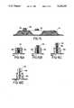
- FIG. 5is a cross-sectional view of the embodiment of the thermal compress shown in FIG. 3 along the line 5--5 illustrating spot welding to hold the wall of the inner compartment together in predetermined areas;
- FIG. 6is a cross-sectional view of an alternate embodiment of the thermal compress at the same section as 5--5 and illustrating tethers that hold the walls of the inner compartment in spaced relationship;
- FIG. 7is a diagrammatic representation of the novel pressure cuff placed about the knee of an extended leg
- FIG. 8is a view of the novel device placed on a flexed knee with one form of air pump attached thereto;
- FIG. 9is a view of the novel thermal compress placed on a flexed knee with the air pump attached thereto and folded after the compress has been inflated;
- FIG. 10is a side view of the compress quick disconnect in its connected relationship with the air pump hose
- FIG. 11is a side view of the compress quick disconnect after being disconnected from the air pump hose
- FIG. 12is a top view of one embodiment of the portable air pump used to pressurize the thermal cuff.
- FIG. 13is a cross-sectional view of the air pump taken along lines 13--13 of FIG. 2;
- FIG. 14is a side view of a bulb-type pump that may be used to pressurize the thermal cuff
- FIG. 15is a cross-sectional view of a thermal cuff with a pressure gauge thereon;
- FIGS. 16A-16Dare cross-sectional views of the pressure gauge in its various positions to indicate pressure in the thermal cuff compartments.
- FIG. 17is a plan view of an alternate embodiment of the novel compress that includes an extension for covering and applying cold and some moderate compression to the area in front of the knee and just below the patella.
- the novel thermal compress of the present inventioncan be used to apply cold or hot temperatures to the human body, it will be described herein with respect to providing a cold temperature where its greatest use is anticipated.
- the preferred embodiment of the novel thermal compress device or cuffdesignated generally by the numeral 10 is designed to be applied to the knee of the leg of an individual.
- the cuff 10has an upper transverse portion 12 and lower depending arms 13 and 14 extending from the upper portion 12.
- the cuff 10can be wrapped about the knee portion of a leg.
- the opening designated by the numeral 18is in the cuff 10 is intended to receive the knee cap or patella as will be shown hereafter. In this way, the pressure and temperature are not applied to the patella or kneecap of the person wearing the compress.
- a proximal strap 20 and a distal strap 22are attached to thermal compress cuff 10 at tabs or wings 21 and 23, respectively, on arm 14.
- Strap 22is made of any well-known flexible material having a portion with a fastening material thereon known as Velcro.
- Strap 20is made of a relatively inelastic material. Straps 20 and 22 are arranged for attaching relationship with mating Velcro strips 32 and 34 mounted on opposing tabs or wings 31 and 33, respectively, on arm 13 of thermal compress cuff 10. Further, the straps 20 and 22 have resilient foam attachments 28 and 30 attached respectively thereto for the purpose of providing a cushion for the underside of the person's leg to which the thermal compress cuff 10 is attached.
- a neck 25has a closable opening 26 therein for admitting the cold liquid to the interior of the cuff 10.
- the cuff 10is bifurcated beginning with opening 18, thus separating depending arms 13 and 14. This permits adjustment for knee angle and width.
- the gap between the arms 13 and 14includes a truncated triangular gap 19.
- the gap 19changes the profile of the applied cuff 10 from flat to conical for better conformation of the arms 13 and 14 to the leg when the knee is in the flexed position.
- Velcro fastener 34 and elastic strap 22connect the depending arms 13 and 14 together under (or behind) the leg while strap 36 and mating Velcro strip 38 connect the arms 13 and 14 together over the top of the leg.
- the upper (proximal) and lower (distal) straps 20 and 22are placed so as to avoid the popliteal area of the knee and minimize constriction thereof.
- This constructionpermits bending adjustment of the cuff for different degrees of flexation of the knee from full extension to about 30°.
- the arms 13 and 14could be fixed permanently to each other with flexible connectors without providing for adjustment if desired.
- the use of the flexible and elastic strap 22 under the legtends to limit the constriction of the leg below the knee and thus minimizes venous constriction below the knee which is desirable during treatment of the knee by use of the cuff 10.
- FIG. 2is a cross-sectional view of the novel cuff.
- the device 10includes a fluid impervious chamber formed so as to be divided into inner and outer generally coextensive compartments 42 and 44, respectively.
- Compartment 42has an outer wall 52 and compartment 44 has an outer wall 54.
- Each of the compartments 42 and 44has a common inner wall 56.
- the inner compartment 42is adapted for receiving and containing the thermal fluid in a desired temperature range in generally uniform and abutting contact via wall 52 with the encompassed portion of the leg being treated.
- a Y-shaped internal syphon having tubes 27 and 29connects to neck 25 and closable opening 26 for filling and draining the fluid from inner compartment 42.
- Tubes 27 and 29are formed of a material such as plastic and are approximately 5/16" on the inside diameter. They extend from the fill opening 26 to the distal end of each of the arms 13 and 14 as shown in phantom lines in FIG. 1. Thus, even though the fill port 26 is at the top of the compress, all of the fluid can be completely drained from the bottom.
- An open-cell urethane foam material 46 approximately 0.30" thick that will compress to about half its normal thickness under a 1 psi loadis suitable for use in outer compartment 44 for insulating the underlying inner compartment 42, for minimizing sweating of the outer compartment 44 and for maintaining the shape of the cuff 10 while permitting conformation of the cuff 10 while emcompassing the person's leg.
- the proximal step 20 and distal strap 22secure the cuff to the leg snugly but not tightly as described earlier.
- the cuffmay be pressurized with a fluid from an elevated container using a closed cycle system.
- a cooler or container 88which may be either a flexible pouch or a rigid container, holds a fluid such as ice and water sufficient for six to eight hours of cryotherapy.
- the cooler 88if a rigid container, has a lid 84 and a handle 85 and is coupled by a hose 90 to the connection 26 on the cuff 10.
- the cooler 88is elevated above the limb as illustrated in FIG. 7 and the ice chilled water flows into the cuff 10. Compression of the limb, due to the gravity flow of the ice water, is proportional to the elevation of the cooler 88 with respect to the cuff 10.
- a manually operated valve 92allows the flow of ice water to be stopped when the desired pressure is reached by manually closing the valve. Thus, the pressure is sealed in the cuff and skin temperature falls rapidly. After 15 to 30 minutes, body heat will warm the water in the cuff 10. The water is then "rechilled” by reversing the cycle. The cooler is lowered below the leg and the valve 92 is opened. The warmed water is drained by the syphon system back into the cooler 88. After a short interval allowing mixing of the water with the ice, the cooler 88 is again elevated and the cuff-filling process repeated.
- a closed chilled water systemis used and the water is recirculated between the container and the cuff in the closed system to maintain the water at the desired temperature.
- the Y-shaped internal syphon tubes 27 and 29extend to the distal areas of the inner compartment 42 of arms 13 and 14, thus either draining the warm water from or filling the compartment with cold water as set forth above.
- the vent 35(FIGS. 1 and 2) may be opened to allow air to escape as the chilled water is entering the compartment 42.
- the cuff 10As thermal fluid fills the inner compartment 42, it expands the cuff 10, compresses the limb 16 and tightens the straps 20 and 22. Normally, the cuff 10 would expand uniformly and both straps would be similarly tensioned around the upper and lower limb. Because most of the swelling after knee surgery takes place in the suprapatellar pouch--immediately above the knee, it is medically desirable to have more cold and compression in the proximal area above the patella and less in the distal area covered by the arms 13 and 14. Additionally, the risk of undesirable constriction is greater under the distal strap below the knee.
- the present inventionincludes means to restrict the amount of expansion of the fluid compartment in the distal area of the cuff or compress 10 but not in the proximal area. This causes more fluid to remain in the upper area 12 and less in the arms 13 and 14. This results in less tightening of the lower strap 22.
- the simplest and preferred manner of accomplishing thisis to spot weld the two sides 52 and 56 of the chamber in the area 57 of the distal portion of arms 13 and 14, similar to the manner of a quilt, as illustrated. (See FIGS. 2 & 5).
- An alternativeis to weld a short tethering strap 57' to each internal surface 52 and 56 as shown in FIG. 6, to permit some but limited expansion in the immediate area. Tests show that pressure under the distal strap 22 is reduced by about a third by this dual technique of an elastic strap and restricted expansion of the chamber.
- the outer compartment 44contains foam 46 that overlies the thermal fluid-filled compartment 42.
- the foam-filled outer compartment 44performs two functions. First, it insulates the underlying cold fluid compartment 42, thereby maintaining the cold temperature for a longer period of time while preventing sweating of the cuff upper surface 54. Second, it maintains the shape of the cuff 10 while permitting conformation of the cuff around the leg and it reduces sagging of the 30 device under the weight of the fluid.
- the foammay be an open-cell urethane foam about 0.30 inches thick that will compress to about half its normal thickness under a 1 psi load.
- external compressionis used to cause the outer wall 52 of the cold fluid compartment 42 to more uniformly engage the body area being treated. This is accomplished by applying a pressurized fluid such as air through a selectively closable opening 40 shown in detail in FIGS. 9-11.
- the selectively closable opening 40(as shown in FIG. 3) is attached to the outer compartment 44 for permitting pressurized fluid such as air to be introduced therein sufficient to force the inner compartment 42 with its thermal fluid in pressure engagement with the encompassed portion of the leg. This increases the pressure in the foam-filled chamber 44.
- FIGS. 8, 9, 12 and 13One form of a pump that may be coupled to orifice 40 for applying the supplemental pressure is illustrated in FIGS. 8, 9, 12 and 13.
- the pumpis designated generally by the numeral 58. It has a rectangular body portion 60 to which is attached a strap 59 having a Velcro strip 61 thereon.
- a hose 62extends from body portion 60 to carry the compressed air to opening 40 in the outer compartment or chamber 44 of the inflatable cuff.
- the unitmay be folded about center section 66 and Velcro strap 59 wrapped around the open end of the air pump 58 to have mating contact with a second Velcro strip 70 (FIG. 13) on the obverse side of the pump 58.
- FIG. 13A cross section of the novel pump is shown in FIG. 13.
- the pump 58is actually an air foam cell that is approximately six inches long and two inches wide and has strap 59 attached therewith with the Velcro strip 61 thereon.
- the lower portion 72is an air impervious resilient material such as plastic and has attached thereto first and second substantially rigid surfaces 74 and 76 which may be, for instance, thin, rigid plastic layers. Plastic layers 74 and 76 are separated from each other by a small gap 78.
- a cellular foam layer 80has a portion removed to form an indentation 66 and allow the foam cell to be easily folded about the indentation.
- An outer pliable surface 82such as this plastic is placed over the foam 80 and sealed to the lower plastic surface 72 to form an airtight compartment.
- Hose 62communicates with the inside of the airtight compartment.
- the air cellWhen the air cell is folded about separation 78 and indentation 66 as shown in FIGS. 8 and 9, the entrapped air in the cell is forced out via tube 62 and orifice 64 into the cuff 10 as shown in FIG. 10.
- the hose 62By clamping the selectively closable opening 40 with quick disconnect clamp 41, the hose 62 may be disconnected from orifice 64, as shown in FIG. 11, and the air cell 58 will expand to its straight configuration as in FIG. 12. In this process the cell 58 accumulates air through hose 62 to the interior thereof.
- the hose 62can then again be coupled to the cuff 10 to add additional air as needed when the air cell 58 is again folded.
- a one-way valvemay be coupled to the cell to allow air in but not out.
- the hose 62would not have to be disconnected from the orifice 64.
- only one pressurization cycle of the pump 58is required to sufficiently pressurize the cuff 10.
- the pump 58When the pump 58 is not in use, it may be disconnected from the cuff 10 and folded as illustrated in FIG. 9 with the strap 59 passing around the open end of the pump and the Velcro strip 61 thereon cooperating with the Velcro strip 70 on the bottom of the air cell 58 to hold the pump in the closed shape as shown.
- a bulb 63as shown in FIG. 14 and well known in the art, may be used to pressurize the outer compartment 44.
- the end 65 of bulb 63may be inserted in a hose such as hose 62 or directly in connector orifice 40 to pressurize outer compartment 44.
- FIG. 15is a cross-sectional view of the novel cuff in which a gauge means housing 100 has been placed to indicate the pressure in the outer compartment 44 so as to prevent over inflation.
- the gauge means housing 100may include an expandable bellows 102 such as shown in FIG. 16A (where it is entirely compressed) in communication with chamber 44 via aperture 101.
- the bellows 102is held in place with no pressure in compartment 44 by resilient means such as a spring 104.
- the bellows 102begins to expand against the force of spring 104 and protrudes from the housing 100 as illustrated in FIG. 16B.
- the bellows 102becomes fully extended as illustrated in FIG. 16C.
- the bellowsmay have markings 106 thereon as shown in FIG. 16D to indicate the amount of pressure within compartment 44.
- the marks 106may simply be reference points to enable the user to adjust the same pressure in the compartment 44 each time the thermal compress is used.
- FIG. 17discloses the compress having the means for supplying cold and some moderate degree of compression to the area in front of the leg just below the patella of the knee. As can be seen in FIG.
- a hollow triangular cuff section 110forms a part of the distal end of the hollow arm 14 in substantially superimposed relationship with the triangular open area 19 to allow cold and compression to be applied to the area adjacent, in front of and below the patella of the knee.
- the triangular cuff section 110also has a tethering dimple 57 to restrict the amount of fluids entering therein and thus controlling the amount of pressure that can be applied to the area in front of the knee and below the patella.
- the triangular cuff section 110may include adjacent thereto a pad for securing the Velcro strip 36. With such relationship, when the distal ends of the arms 13 and 14 are drawn together, they overlap so that the area of the knee just below the patella is covered with cold and some moderate compression.
- the compressmay have one or two chambers as previously discussed and is used in a similar manner.
- a novel thermal compress cuffwhich is adapted to encompass a knee of a person. It has a substantially fluid impervious chamber formed of flexible material having an upper portion and depending arms extending from the upper portion.
- the chamberis divided into inner and outer compartments each having an outer wall and a common wall.
- the inner compartmentis adapted for receiving and containing a thermal fluid and is in abutting contact with the encompassed portion of the person's knee.
- An openingis formed in the inner compartment for receiving a thermal fluid through a hose from an external container. As the container is lifted above the knee, the thermal fluid is under pressure and pressurizes the inner compartment to an amount corresponding to the height of the container above the knee.
- Open-cell urethane foam in the outer compartmentinsulates the underlying inner compartment thus minimizing sweating of the outer compartment in humid climates. It also maintains the shape of the device while permitting conformation of the device encompassing the person's limb.
- a selectively closable openingis attached to the outer compartment for permitting pressurized fluid to be introduced therein sufficient to force the inner compartment with its thermal fluid in pressure engagement with the encompassed portion of the knee.
- Means for restricting expansion of the cavity in the distal area of the armsis provided to cause a greater amount of thermal fluid to remain in the proximal area (providing more pressure) and allow less thermal fluid in the distal area of the arms.
- a novel portable air cellis provided to pressurize the cuff as needed.
- the container 88may be connected directly to neck 25 (FIG. 1) via a quick disconnect such as the type made by Colder Fittings (Model Nos. PLCD 170-06 & PLCD 220-06).
- neck 25 and opening 26may be made large enough to permit the direct introduction of ice cubes and water in lieu of a separate container 88.
- the outer compartment 44may be inflated orally by a tube connected to orifice 40.
Landscapes
- Health & Medical Sciences (AREA)
- Animal Behavior & Ethology (AREA)
- Biomedical Technology (AREA)
- Heart & Thoracic Surgery (AREA)
- Vascular Medicine (AREA)
- Life Sciences & Earth Sciences (AREA)
- Engineering & Computer Science (AREA)
- General Health & Medical Sciences (AREA)
- Public Health (AREA)
- Veterinary Medicine (AREA)
- Orthopedics, Nursing, And Contraception (AREA)
- Thermotherapy And Cooling Therapy Devices (AREA)
- Separation By Low-Temperature Treatments (AREA)
- Steroid Compounds (AREA)
Abstract
Description
Claims (9)
Priority Applications (7)
| Application Number | Priority Date | Filing Date | Title |
|---|---|---|---|
| US07/737,402US5230335A (en) | 1991-01-23 | 1991-07-29 | Thermal compress system |
| AU12623/92AAU663075B2 (en) | 1991-01-23 | 1992-01-08 | Thermal compress system |
| DE69230370TDE69230370T2 (en) | 1991-01-23 | 1992-01-08 | THERMAL COMPRESSING SYSTEM |
| PCT/US1992/000131WO1992013506A2 (en) | 1991-01-23 | 1992-01-08 | Thermal compress system |
| CA002101272ACA2101272A1 (en) | 1991-01-23 | 1992-01-08 | Thermal compress system |
| EP92905129AEP0572476B1 (en) | 1991-01-23 | 1992-01-08 | Thermal compress system |
| US08/109,382US5466250A (en) | 1991-01-23 | 1993-08-19 | Automatic fluid compress and circulating system |
Applications Claiming Priority (2)
| Application Number | Priority Date | Filing Date | Title |
|---|---|---|---|
| US07/644,835US5314455A (en) | 1991-01-23 | 1991-01-23 | Thermal compress system |
| US07/737,402US5230335A (en) | 1991-01-23 | 1991-07-29 | Thermal compress system |
Related Parent Applications (1)
| Application Number | Title | Priority Date | Filing Date |
|---|---|---|---|
| US07/644,835Continuation-In-PartUS5314455A (en) | 1991-01-23 | 1991-01-23 | Thermal compress system |
Related Child Applications (1)
| Application Number | Title | Priority Date | Filing Date |
|---|---|---|---|
| US08/109,382Continuation-In-PartUS5466250A (en) | 1991-01-23 | 1993-08-19 | Automatic fluid compress and circulating system |
Publications (1)
| Publication Number | Publication Date |
|---|---|
| US5230335Atrue US5230335A (en) | 1993-07-27 |
Family
ID=27094560
Family Applications (1)
| Application Number | Title | Priority Date | Filing Date |
|---|---|---|---|
| US07/737,402Expired - LifetimeUS5230335A (en) | 1991-01-23 | 1991-07-29 | Thermal compress system |
Country Status (6)
| Country | Link |
|---|---|
| US (1) | US5230335A (en) |
| EP (1) | EP0572476B1 (en) |
| AU (1) | AU663075B2 (en) |
| CA (1) | CA2101272A1 (en) |
| DE (1) | DE69230370T2 (en) |
| WO (1) | WO1992013506A2 (en) |
Cited By (120)
| Publication number | Priority date | Publication date | Assignee | Title |
|---|---|---|---|---|
| US5387185A (en)* | 1993-11-08 | 1995-02-07 | Aircast, Incorporated | Knee immobilizer splint |
| US5409500A (en)* | 1992-06-22 | 1995-04-25 | Ergomed, Inc. | Versatile therapeutic cold pack |
| US5411541A (en)* | 1993-08-05 | 1995-05-02 | Oansh Designs Ltd. | Portable fluid therapy device |
| US5411542A (en)* | 1993-10-20 | 1995-05-02 | Hollister Incorporated | Post-operative thermal blanket for ankle and foot |
| US5456701A (en)* | 1994-02-25 | 1995-10-10 | Southwest Technologies, Inc. | Therapy member including internal bladder with surrounding pliable gel |
| US5466250A (en)* | 1991-01-23 | 1995-11-14 | Aircast, Inc. | Automatic fluid compress and circulating system |
| US5470353A (en)* | 1993-10-20 | 1995-11-28 | Hollister Incorporated | Post-operative thermal blanket |
| USD365399S (en) | 1994-05-10 | 1995-12-19 | Medela, Inc. | Heating pad |
| US5476490A (en)* | 1994-05-10 | 1995-12-19 | Medela, Inc. | Heating pad |
| USD367711S (en) | 1994-07-18 | 1996-03-05 | Simmons William J | Combined hot and cold pack vest and harness |
| US5496358A (en)* | 1993-06-14 | 1996-03-05 | Sport Wrapz, Inc. | Thermal wrap for a body member |
| US5634890A (en)* | 1995-05-09 | 1997-06-03 | Aquasage, Inc. | Water massage therapy device and method for using the same |
| US5637077A (en)* | 1995-10-30 | 1997-06-10 | Smith & Nephew Casting, Inc. | Custom-molded ankle brace |
| US6117164A (en) | 1997-06-06 | 2000-09-12 | Dj Orthopedics, Llc | Flexible multijoint therapeutic pads |
| US6230501B1 (en) | 1994-04-14 | 2001-05-15 | Promxd Technology, Inc. | Ergonomic systems and methods providing intelligent adaptive surfaces and temperature control |
| US6238427B1 (en) | 1999-03-30 | 2001-05-29 | John G. Matta | Therapeutic heat transfer pads |
| US6409691B1 (en) | 1999-08-02 | 2002-06-25 | Daos Limited | Liquid brace |
| US20020107558A1 (en)* | 1998-04-23 | 2002-08-08 | Clifton Guy L. | Heat transfer blanket for and method of controlling a patient's temperature |
| US6440159B1 (en) | 2000-03-01 | 2002-08-27 | Joseph H. Edwards | Multiuse therapy wrap |
| US6464658B1 (en) | 2000-12-07 | 2002-10-15 | Bsn Medical Inc. | Custom-formable knee immobilizer product, knee immobilizer and method |
| US20030130600A1 (en)* | 2001-12-13 | 2003-07-10 | Branch Thomas P. | Shoulder extension control device |
| US6669660B2 (en)* | 1998-08-10 | 2003-12-30 | Thomas P. Branch | Orthotic apparatus and method for using same |
| US6695872B2 (en) | 2000-01-28 | 2004-02-24 | Coolsystems, Inc. | Therapy component of an animate body heat exchanger and method of manufacturing such component |
| US20040064168A1 (en)* | 2002-09-26 | 2004-04-01 | Eischen Clement G. | Thermal pack apparatus |
| US20040068310A1 (en)* | 2002-10-08 | 2004-04-08 | Howard Edelman | Therapy pad |
| US20040158303A1 (en)* | 2002-04-29 | 2004-08-12 | Medcool, Inc. | Method and device for rapidly inducing and then maintaining hypothermia |
| USD500140S1 (en) | 2003-08-29 | 2004-12-21 | Dj Orthopedics, Llc | Thermal therapy pad |
| USD505727S1 (en) | 2003-08-29 | 2005-05-31 | Dj Orthopedics, Llc | Thermal therapy pad |
| USD506553S1 (en) | 2004-02-23 | 2005-06-21 | Tyco Healthcare Group Lp | Compression sleeve |
| US20050187499A1 (en)* | 2004-02-23 | 2005-08-25 | Heather Gillis | Compression apparatus |
| USD510626S1 (en) | 2003-08-29 | 2005-10-11 | Dj Orthopedics, Llc | Thermal therapy pad |
| US20050251076A1 (en)* | 2004-04-09 | 2005-11-10 | Branch Thomas P | Method and apparatus for multidirectional positioning of a shoulder |
| US20050256556A1 (en)* | 2004-05-17 | 2005-11-17 | Coolsystems, Inc. | Modular apparatus for therapy of an animate body |
| US20060030915A1 (en)* | 2003-08-04 | 2006-02-09 | Medcool, Inc. | Method and apparatus for reducing body temperature of a subject |
| USD515218S1 (en) | 2004-01-22 | 2006-02-14 | Dj Orthopedics, Llc | Thermal therapy pad |
| US7008445B2 (en) | 2002-04-29 | 2006-03-07 | Medcool, Inc. | Method and device for rapidly inducing hypothermia |
| USD517695S1 (en) | 2004-02-23 | 2006-03-21 | Tyco Healthcare Group Ip | Compression sleeve |
| USD523147S1 (en) | 2004-02-23 | 2006-06-13 | Tyco Healthcare Group Lp | Compression sleeve |
| US20060155350A1 (en)* | 2005-01-10 | 2006-07-13 | Lu Nan C | Pressure adjustable structure for ice compress |
| USD527108S1 (en) | 2003-10-10 | 2006-08-22 | Dj Orthopedics, Llc | Thermal therapy pad |
| USD532523S1 (en) | 2003-08-29 | 2006-11-21 | Dj Orthopedics, Llc | Thermal therapy pad |
| US7219449B1 (en) | 1999-05-03 | 2007-05-22 | Promdx Technology, Inc. | Adaptively controlled footwear |
| US20070161932A1 (en)* | 2005-07-25 | 2007-07-12 | Djo, Llc | Temperature regulated compression brace |
| US20080039781A1 (en)* | 2006-08-08 | 2008-02-14 | Tammy Bjorge | Support device for a breast pump |
| US20080097561A1 (en)* | 2006-10-18 | 2008-04-24 | Medcool, Inc. | Dual cycle thermal system and method of use |
| US20080249455A1 (en)* | 2007-04-09 | 2008-10-09 | Tyco Healthcare Group Lp | Compression Device with Improved Moisture Evaporation |
| US20080249449A1 (en)* | 2007-04-09 | 2008-10-09 | Tyco Healthcare Group Lp | Methods of Making Compression Device with Improved Evaporation |
| US20080249447A1 (en)* | 2007-04-09 | 2008-10-09 | Tyco Healthcare Group Lp | Compression Device Having Cooling Capability |
| US20080249440A1 (en)* | 2007-04-09 | 2008-10-09 | Tyco Healthcare Group Lp | Method of Making Compression Sleeve with Structural Support Features |
| US20080269852A1 (en)* | 2005-04-07 | 2008-10-30 | Medcool, Inc | Methods and Apparatus for Thermal Regulation of a Body |
| US20090066079A1 (en)* | 2007-09-12 | 2009-03-12 | Coolsystems, Inc. | Make-brake connector assembly with opposing latches |
| US7513881B1 (en) | 2005-01-12 | 2009-04-07 | Ossur Hf | Knee immobilizer |
| US20090234317A1 (en)* | 2008-03-13 | 2009-09-17 | Navarro Lissa M | Flexible, flat pouch with port for mixing and delivering powder-liquid mixture |
| USD608006S1 (en) | 2007-04-09 | 2010-01-12 | Tyco Healthcare Group Lp | Compression device |
| US20100030306A1 (en)* | 2002-10-08 | 2010-02-04 | Howard Edelman | Therapeutic Cranial Wrap for a Contrast Therapy System |
| US7658205B1 (en) | 2002-12-19 | 2010-02-09 | Vitalwear, Inc. | Systems for a fluid circuit coupler |
| US7694693B1 (en) | 2002-10-08 | 2010-04-13 | Vitalwear, Inc. | Mixing valve for a contrast therapy system |
| US7717869B2 (en) | 2005-02-18 | 2010-05-18 | Eischco, Inc. | Pressure maintained inflatable boot |
| US20100137951A1 (en)* | 2002-12-12 | 2010-06-03 | Medcool, Inc. | Method and apparatus for reducing body temperature of a subject |
| US20100240668A1 (en)* | 2006-07-21 | 2010-09-23 | Watterson D M | Myosin Light Chain Kinase Inhibitor Compounds, Compositions and Related Methods of Use |
| US7837638B2 (en) | 2007-02-13 | 2010-11-23 | Coolsystems, Inc. | Flexible joint wrap |
| US7871387B2 (en) | 2004-02-23 | 2011-01-18 | Tyco Healthcare Group Lp | Compression sleeve convertible in length |
| US20110125183A1 (en)* | 2009-11-24 | 2011-05-26 | Circaid Medical Products | Graduated Compression Device for the Treatment of Circulatory Disorders |
| US8021388B2 (en) | 2007-04-09 | 2011-09-20 | Tyco Healthcare Group Lp | Compression device with improved moisture evaporation |
| US8029451B2 (en) | 2005-12-12 | 2011-10-04 | Tyco Healthcare Group Lp | Compression sleeve having air conduits |
| US8029450B2 (en) | 2007-04-09 | 2011-10-04 | Tyco Healthcare Group Lp | Breathable compression device |
| US8034007B2 (en) | 2007-04-09 | 2011-10-11 | Tyco Healthcare Group Lp | Compression device with structural support features |
| US8052628B1 (en) | 2002-10-08 | 2011-11-08 | Vitalwear, Inc. | Spinal column brace for a contrast therapy system |
| US8100956B2 (en) | 2006-05-09 | 2012-01-24 | Thermotek, Inc. | Method of and system for thermally augmented wound care oxygenation |
| US20120031142A1 (en)* | 2010-08-05 | 2012-02-09 | Hyper Ice, Inc. | Ice Bag with Air Release Valve for Therapeutic Treatment |
| US8114117B2 (en) | 2008-09-30 | 2012-02-14 | Tyco Healthcare Group Lp | Compression device with wear area |
| US8128672B2 (en) | 2006-05-09 | 2012-03-06 | Thermotek, Inc. | Wound care method and system with one or both of vacuum-light therapy and thermally augmented oxygenation |
| US8128584B2 (en) | 2007-04-09 | 2012-03-06 | Tyco Healthcare Group Lp | Compression device with S-shaped bladder |
| US8162861B2 (en) | 2007-04-09 | 2012-04-24 | Tyco Healthcare Group Lp | Compression device with strategic weld construction |
| USD662213S1 (en) | 2007-04-10 | 2012-06-19 | Thermotek, Inc. | Knee wrap |
| US8235923B2 (en) | 2008-09-30 | 2012-08-07 | Tyco Healthcare Group Lp | Compression device with removable portion |
| US8248798B2 (en) | 2004-08-12 | 2012-08-21 | Thermotek, Inc. | Thermal control system for rack mounting |
| US20130012847A1 (en)* | 2011-06-17 | 2013-01-10 | Coolsystems, Inc. | Adjustable patient therapy device |
| WO2013013059A1 (en)* | 2011-07-20 | 2013-01-24 | Scr Inc. | Athletic cooling and heating systems, devices and methods |
| USD679023S1 (en) | 2004-07-19 | 2013-03-26 | Thermotek, Inc. | Foot wrap |
| US8425579B1 (en) | 2002-10-08 | 2013-04-23 | Vitalwear, Inc. | Therapeutic knee brace for a contrast therapy system |
| US8506508B2 (en) | 2007-04-09 | 2013-08-13 | Covidien Lp | Compression device having weld seam moisture transfer |
| US8529613B2 (en) | 2006-10-18 | 2013-09-10 | Medcool, Inc. | Adjustable thermal cap |
| US8539647B2 (en) | 2005-07-26 | 2013-09-24 | Covidien Ag | Limited durability fastening for a garment |
| US8574278B2 (en) | 2006-05-09 | 2013-11-05 | Thermotek, Inc. | Wound care method and system with one or both of vacuum-light therapy and thermally augmented oxygenation |
| US8597217B2 (en) | 2010-12-30 | 2013-12-03 | Coolsystems, Inc. | Reinforced therapeutic wrap and method |
| US20140025145A1 (en)* | 2012-07-19 | 2014-01-23 | Christopher Kirkman | Segmented ice wrap |
| US8652079B2 (en) | 2010-04-02 | 2014-02-18 | Covidien Lp | Compression garment having an extension |
| US8715330B2 (en) | 2009-10-22 | 2014-05-06 | Coolsystems, Inc. | Temperature and flow control methods in a thermal therapy device |
| US8753383B2 (en) | 2003-07-18 | 2014-06-17 | Thermotek, Inc. | Compression sequenced thermal therapy system |
| US8758419B1 (en) | 2008-01-31 | 2014-06-24 | Thermotek, Inc. | Contact cooler for skin cooling applications |
| US8778005B2 (en) | 2003-07-18 | 2014-07-15 | Thermotek, Inc. | Method and system for thermal and compression therapy relative to the prevention of deep vein thrombosis |
| US20140316314A1 (en)* | 2011-06-14 | 2014-10-23 | Portable Therapeutix, LLC | Compression device |
| US8945027B2 (en) | 2010-09-23 | 2015-02-03 | Munish K. Batra | Heated compression therapy system and method |
| US8979915B2 (en) | 2010-04-19 | 2015-03-17 | Pulsar Scientific, LLC | Separable system for applying compression and thermal treatment |
| US9119705B2 (en) | 1998-06-08 | 2015-09-01 | Thermotek, Inc. | Method and system for thermal and compression therapy relative to the prevention of deep vein thrombosis |
| US9125787B2 (en) | 2011-09-30 | 2015-09-08 | Covidien Lp | Compression garment having a foam layer |
| US9205021B2 (en) | 2012-06-18 | 2015-12-08 | Covidien Lp | Compression system with vent cooling feature |
| USD757286S1 (en) | 2014-07-07 | 2016-05-24 | Deroyal Industries, Inc. | Thermal therapy blanket |
| USD757954S1 (en) | 2014-07-07 | 2016-05-31 | Deroyal Industries, Inc. | Thermal therapy blanket |
| US9402779B2 (en) | 2013-03-11 | 2016-08-02 | Covidien Lp | Compression garment with perspiration relief |
| US9615967B2 (en) | 2010-12-30 | 2017-04-11 | Coolsystems, Inc. | Reinforced therapeutic wrap and method |
| US9669233B2 (en) | 2013-11-11 | 2017-06-06 | Thermotek, Inc. | Method and system for wound care |
| US9872812B2 (en) | 2012-09-28 | 2018-01-23 | Kpr U.S., Llc | Residual pressure control in a compression device |
| US10016583B2 (en) | 2013-03-11 | 2018-07-10 | Thermotek, Inc. | Wound care and infusion method and system utilizing a thermally-treated therapeutic agent |
| WO2018183769A3 (en)* | 2017-03-29 | 2018-11-08 | Weinstein Randy H | A thermal pack that approximates a curved three-dimensional surface |
| US10149927B2 (en) | 2012-04-24 | 2018-12-11 | Thermotek, Inc. | Method and system for therapeutic use of ultra-violet light |
| US10300180B1 (en) | 2013-03-11 | 2019-05-28 | Thermotek, Inc. | Wound care and infusion method and system utilizing a therapeutic agent |
| US10456320B2 (en) | 2013-10-01 | 2019-10-29 | Coolsystems, Inc. | Hand and foot wraps |
| US10512587B2 (en) | 2011-07-27 | 2019-12-24 | Thermotek, Inc. | Method and apparatus for scalp thermal treatment |
| US10751221B2 (en) | 2010-09-14 | 2020-08-25 | Kpr U.S., Llc | Compression sleeve with improved position retention |
| US10765785B2 (en) | 2004-07-19 | 2020-09-08 | Thermotek, Inc. | Wound care and infusion method and system utilizing a therapeutic agent |
| US10859295B2 (en) | 2016-04-13 | 2020-12-08 | ZeoThermal Technologies, LLC | Cooling and heating platform |
| US10918557B2 (en) | 2009-11-24 | 2021-02-16 | Medi Manufacturing, Inc. | Two-part non-planar graduated compression device for the treatment of circulatory disorders |
| US11318042B2 (en) | 2016-09-29 | 2022-05-03 | Randy H Weinstein | Thermal pack that conforms to curved surfaces |
| US20230084612A1 (en)* | 2020-02-14 | 2023-03-16 | Vestel Elektronik Sanayi Ve Ticaret A.S. | Cooling system comprising cells for receiving a coolant |
| US11638675B2 (en) | 2018-11-07 | 2023-05-02 | Zenith Technical Innovations, Llc | System and method for heat or cold therapy and compression therapy |
| US11672693B2 (en) | 2014-08-05 | 2023-06-13 | Avent, Inc. | Integrated multisectional heat exchanger |
| US11779508B2 (en) | 2021-06-25 | 2023-10-10 | Aquilo Sports Llc | Therapeutic pressure, thermal, and/or other treatment modality systems and methods |
| US11857491B2 (en) | 2019-03-13 | 2024-01-02 | Breg, Inc. | Integrated cold therapy-compression therapy assembly and associated treatment protocols |
Families Citing this family (4)
| Publication number | Priority date | Publication date | Assignee | Title |
|---|---|---|---|---|
| US5728058A (en)* | 1995-06-29 | 1998-03-17 | The Procter & Gamble Company | Elastic knee wrap |
| DE202007007570U1 (en) | 2007-05-25 | 2008-10-09 | Barbknecht, Ingrid | Device for receiving a cooling medium for cooling a body part |
| WO2014184324A1 (en)* | 2013-05-15 | 2014-11-20 | Universite Libre De Bruxelles | Decongestion garment for treating lymphedema |
| CH710788B1 (en)* | 2015-02-27 | 2018-06-29 | Hauser Stefan | Heat clothing. |
Citations (15)
| Publication number | Priority date | Publication date | Assignee | Title |
|---|---|---|---|---|
| US1732380A (en)* | 1928-08-21 | 1929-10-22 | Sarason David | Apparatus for the external treatment of parts of the body by water |
| US2026747A (en)* | 1935-03-16 | 1936-01-07 | William P B Nemzek | Gravity thermal dilator |
| US2832336A (en)* | 1955-06-23 | 1958-04-29 | Davis | Physiotherapy device |
| US3584819A (en)* | 1969-05-23 | 1971-06-15 | Amp Inc | Storage reel |
| US3633567A (en)* | 1969-08-11 | 1972-01-11 | Survival Technology | Pneumatically actuated pressure dressing |
| US3871381A (en)* | 1971-12-30 | 1975-03-18 | Donald J Roslonski | Cold compress device |
| US3901225A (en)* | 1974-01-02 | 1975-08-26 | Jerry W Sconce | Inflatable splint |
| US4139004A (en)* | 1977-02-17 | 1979-02-13 | Gonzalez Jr Harry | Bandage apparatus for treating burns |
| US4338944A (en)* | 1980-06-16 | 1982-07-13 | The Kendall Company | Therapeutic device |
| US4407276A (en)* | 1981-01-22 | 1983-10-04 | Medical Designs, Inc. | Brace for articulated limbs |
| US4628932A (en)* | 1984-06-11 | 1986-12-16 | Morris Tampa | Knee ice pack |
| US4688572A (en)* | 1986-01-21 | 1987-08-25 | Tecnol, Inc. | Medical/sports thermal pack |
| US4872448A (en)* | 1986-10-22 | 1989-10-10 | Johnson Jr Glenn W | Knee brace having adjustable inflatable U-shaped air cell |
| US4951665A (en)* | 1989-02-08 | 1990-08-28 | Hollister Incorporated | Insulating, anti-kinking Y connector for arthroscopic surgery and method of making |
| US4964402A (en)* | 1988-08-17 | 1990-10-23 | Royce Medical Company | Orthopedic device having gel pad with phase change material |
Family Cites Families (2)
| Publication number | Priority date | Publication date | Assignee | Title |
|---|---|---|---|---|
| DE3341137A1 (en)* | 1983-11-14 | 1985-05-23 | Helmut 7804 Glottertal Rees | Cooling pressure quick bandage |
| US4976262A (en)* | 1989-01-27 | 1990-12-11 | Jed Palmacci | Ice bag holding device |
- 1991
- 1991-07-29USUS07/737,402patent/US5230335A/ennot_activeExpired - Lifetime
- 1992
- 1992-01-08EPEP92905129Apatent/EP0572476B1/ennot_activeExpired - Lifetime
- 1992-01-08WOPCT/US1992/000131patent/WO1992013506A2/enactiveIP Right Grant
- 1992-01-08DEDE69230370Tpatent/DE69230370T2/ennot_activeExpired - Fee Related
- 1992-01-08CACA002101272Apatent/CA2101272A1/ennot_activeAbandoned
- 1992-01-08AUAU12623/92Apatent/AU663075B2/ennot_activeExpired - Fee Related
Patent Citations (15)
| Publication number | Priority date | Publication date | Assignee | Title |
|---|---|---|---|---|
| US1732380A (en)* | 1928-08-21 | 1929-10-22 | Sarason David | Apparatus for the external treatment of parts of the body by water |
| US2026747A (en)* | 1935-03-16 | 1936-01-07 | William P B Nemzek | Gravity thermal dilator |
| US2832336A (en)* | 1955-06-23 | 1958-04-29 | Davis | Physiotherapy device |
| US3584819A (en)* | 1969-05-23 | 1971-06-15 | Amp Inc | Storage reel |
| US3633567A (en)* | 1969-08-11 | 1972-01-11 | Survival Technology | Pneumatically actuated pressure dressing |
| US3871381A (en)* | 1971-12-30 | 1975-03-18 | Donald J Roslonski | Cold compress device |
| US3901225A (en)* | 1974-01-02 | 1975-08-26 | Jerry W Sconce | Inflatable splint |
| US4139004A (en)* | 1977-02-17 | 1979-02-13 | Gonzalez Jr Harry | Bandage apparatus for treating burns |
| US4338944A (en)* | 1980-06-16 | 1982-07-13 | The Kendall Company | Therapeutic device |
| US4407276A (en)* | 1981-01-22 | 1983-10-04 | Medical Designs, Inc. | Brace for articulated limbs |
| US4628932A (en)* | 1984-06-11 | 1986-12-16 | Morris Tampa | Knee ice pack |
| US4688572A (en)* | 1986-01-21 | 1987-08-25 | Tecnol, Inc. | Medical/sports thermal pack |
| US4872448A (en)* | 1986-10-22 | 1989-10-10 | Johnson Jr Glenn W | Knee brace having adjustable inflatable U-shaped air cell |
| US4964402A (en)* | 1988-08-17 | 1990-10-23 | Royce Medical Company | Orthopedic device having gel pad with phase change material |
| US4951665A (en)* | 1989-02-08 | 1990-08-28 | Hollister Incorporated | Insulating, anti-kinking Y connector for arthroscopic surgery and method of making |
Cited By (203)
| Publication number | Priority date | Publication date | Assignee | Title |
|---|---|---|---|---|
| US5466250A (en)* | 1991-01-23 | 1995-11-14 | Aircast, Inc. | Automatic fluid compress and circulating system |
| US5409500A (en)* | 1992-06-22 | 1995-04-25 | Ergomed, Inc. | Versatile therapeutic cold pack |
| US5496358A (en)* | 1993-06-14 | 1996-03-05 | Sport Wrapz, Inc. | Thermal wrap for a body member |
| US5411541A (en)* | 1993-08-05 | 1995-05-02 | Oansh Designs Ltd. | Portable fluid therapy device |
| US5411542A (en)* | 1993-10-20 | 1995-05-02 | Hollister Incorporated | Post-operative thermal blanket for ankle and foot |
| US5470353A (en)* | 1993-10-20 | 1995-11-28 | Hollister Incorporated | Post-operative thermal blanket |
| US5683439A (en)* | 1993-10-20 | 1997-11-04 | Hollister Incorporated | Post-operative thermal blanket |
| US5387185A (en)* | 1993-11-08 | 1995-02-07 | Aircast, Incorporated | Knee immobilizer splint |
| US5456701A (en)* | 1994-02-25 | 1995-10-10 | Southwest Technologies, Inc. | Therapy member including internal bladder with surrounding pliable gel |
| US6230501B1 (en) | 1994-04-14 | 2001-05-15 | Promxd Technology, Inc. | Ergonomic systems and methods providing intelligent adaptive surfaces and temperature control |
| US5476490A (en)* | 1994-05-10 | 1995-12-19 | Medela, Inc. | Heating pad |
| US5897580A (en)* | 1994-05-10 | 1999-04-27 | Prism Enterprises, Inc. | Heated breast pump shield |
| USD365399S (en) | 1994-05-10 | 1995-12-19 | Medela, Inc. | Heating pad |
| USD367711S (en) | 1994-07-18 | 1996-03-05 | Simmons William J | Combined hot and cold pack vest and harness |
| US5634890A (en)* | 1995-05-09 | 1997-06-03 | Aquasage, Inc. | Water massage therapy device and method for using the same |
| US5637077A (en)* | 1995-10-30 | 1997-06-10 | Smith & Nephew Casting, Inc. | Custom-molded ankle brace |
| US6117164A (en) | 1997-06-06 | 2000-09-12 | Dj Orthopedics, Llc | Flexible multijoint therapeutic pads |
| US6352550B1 (en) | 1997-06-06 | 2002-03-05 | Dj Orthopedics, Llc | Flexible multijoint therapeutic pads |
| US20020107558A1 (en)* | 1998-04-23 | 2002-08-08 | Clifton Guy L. | Heat transfer blanket for and method of controlling a patient's temperature |
| US6682550B2 (en)* | 1998-04-23 | 2004-01-27 | The Board Of Regents Of The University Of Texas | Heat transfer blanket for and method of controlling a patient's temperature |
| US9119705B2 (en) | 1998-06-08 | 2015-09-01 | Thermotek, Inc. | Method and system for thermal and compression therapy relative to the prevention of deep vein thrombosis |
| US9180041B2 (en) | 1998-06-08 | 2015-11-10 | Thermotek, Inc. | Compression sequenced thermal therapy system |
| US9433525B2 (en) | 1998-06-08 | 2016-09-06 | Thermotek, Inc. | Compression sequenced thermal therapy system |
| US9877864B2 (en) | 1998-06-08 | 2018-01-30 | Thermotek, Inc. | Compression sequenced thermal therapy system |
| US10507131B2 (en) | 1998-06-08 | 2019-12-17 | Thermotek, Inc. | Method and system for thermal and compression therapy relative to the prevention of deep vein thrombosis |
| US6669660B2 (en)* | 1998-08-10 | 2003-12-30 | Thomas P. Branch | Orthotic apparatus and method for using same |
| US7479121B2 (en) | 1998-08-10 | 2009-01-20 | Branch Thomas P | Orthotic apparatus and method for using same |
| US20090143708A1 (en)* | 1998-08-10 | 2009-06-04 | Branch Thomas P | Orthotic apparatus and method for using same |
| US20110218469A1 (en)* | 1998-08-10 | 2011-09-08 | Branch Thomas P | Orthotic apparatus and method for using same |
| US20040171973A1 (en)* | 1998-08-10 | 2004-09-02 | Branch Thomas P. | Orthotic apparatus and method for using same |
| US8361002B2 (en) | 1998-08-10 | 2013-01-29 | Ermi, Inc. | Orthotic apparatus and method for using same |
| US6238427B1 (en) | 1999-03-30 | 2001-05-29 | John G. Matta | Therapeutic heat transfer pads |
| US7219449B1 (en) | 1999-05-03 | 2007-05-22 | Promdx Technology, Inc. | Adaptively controlled footwear |
| US6409691B1 (en) | 1999-08-02 | 2002-06-25 | Daos Limited | Liquid brace |
| US20040167594A1 (en)* | 2000-01-28 | 2004-08-26 | Coolsystems, Inc. | Therapy component of an animate body heat exchanger |
| US6695872B2 (en) | 2000-01-28 | 2004-02-24 | Coolsystems, Inc. | Therapy component of an animate body heat exchanger and method of manufacturing such component |
| US6440159B1 (en) | 2000-03-01 | 2002-08-27 | Joseph H. Edwards | Multiuse therapy wrap |
| US6464658B1 (en) | 2000-12-07 | 2002-10-15 | Bsn Medical Inc. | Custom-formable knee immobilizer product, knee immobilizer and method |
| US6712780B2 (en) | 2000-12-07 | 2004-03-30 | Bsn Medical Inc. | Custom-formable knee immobilizer product, knee immobilizer and method |
| US20030130600A1 (en)* | 2001-12-13 | 2003-07-10 | Branch Thomas P. | Shoulder extension control device |
| US7547289B2 (en) | 2001-12-13 | 2009-06-16 | Ermi Corporation | Shoulder extension control device |
| US7008445B2 (en) | 2002-04-29 | 2006-03-07 | Medcool, Inc. | Method and device for rapidly inducing hypothermia |
| US20040158303A1 (en)* | 2002-04-29 | 2004-08-12 | Medcool, Inc. | Method and device for rapidly inducing and then maintaining hypothermia |
| US7507250B2 (en) | 2002-04-29 | 2009-03-24 | Medcool, Inc. | Method and device for rapidly inducing hypothermia |
| US20060074469A1 (en)* | 2002-04-29 | 2006-04-06 | Medcool, Inc. | Method and apparatus for reducing body temperature of a subject |
| US7052509B2 (en) | 2002-04-29 | 2006-05-30 | Medcool, Inc. | Method and device for rapidly inducing and then maintaining hypothermia |
| US7621945B2 (en) | 2002-04-29 | 2009-11-24 | Medcool, Inc. | Method and apparatus for reducing body temperature of a subject |
| US20040064168A1 (en)* | 2002-09-26 | 2004-04-01 | Eischen Clement G. | Thermal pack apparatus |
| US8052628B1 (en) | 2002-10-08 | 2011-11-08 | Vitalwear, Inc. | Spinal column brace for a contrast therapy system |
| US7694693B1 (en) | 2002-10-08 | 2010-04-13 | Vitalwear, Inc. | Mixing valve for a contrast therapy system |
| US7211104B2 (en) | 2002-10-08 | 2007-05-01 | Vital Wear, Inc. | Contrast therapy system and method |
| US20100030306A1 (en)* | 2002-10-08 | 2010-02-04 | Howard Edelman | Therapeutic Cranial Wrap for a Contrast Therapy System |
| US20040068310A1 (en)* | 2002-10-08 | 2004-04-08 | Howard Edelman | Therapy pad |
| US8425579B1 (en) | 2002-10-08 | 2013-04-23 | Vitalwear, Inc. | Therapeutic knee brace for a contrast therapy system |
| US8226698B2 (en) | 2002-10-08 | 2012-07-24 | Vitalwear, Inc. | Therapeutic cranial wrap for a contrast therapy system |
| US20100137951A1 (en)* | 2002-12-12 | 2010-06-03 | Medcool, Inc. | Method and apparatus for reducing body temperature of a subject |
| US8454671B2 (en) | 2002-12-12 | 2013-06-04 | Medcool, Inc. | Method and apparatus for reducing body temperature of a subject |
| US7658205B1 (en) | 2002-12-19 | 2010-02-09 | Vitalwear, Inc. | Systems for a fluid circuit coupler |
| US9192539B2 (en) | 2003-07-18 | 2015-11-24 | Thermotek, Inc. | Method and system for thermal and compression therapy relative to the prevention of deep vein thrombosis |
| US10507140B2 (en) | 2003-07-18 | 2019-12-17 | Thermotek, Inc. | Wound care method and system with one or both of vacuum-light therapy and thermally augmented oxygenation |
| US8778005B2 (en) | 2003-07-18 | 2014-07-15 | Thermotek, Inc. | Method and system for thermal and compression therapy relative to the prevention of deep vein thrombosis |
| US8753383B2 (en) | 2003-07-18 | 2014-06-17 | Thermotek, Inc. | Compression sequenced thermal therapy system |
| US9616210B2 (en) | 2003-07-18 | 2017-04-11 | Thermotek, Inc. | Wound care method and system with one or both of vacuum-light therapy and thermally augmented oxygenation |
| US8425580B2 (en) | 2003-07-18 | 2013-04-23 | Thermotek, Inc. | Method of and system for thermally augmented wound care oxygenation |
| US20060030915A1 (en)* | 2003-08-04 | 2006-02-09 | Medcool, Inc. | Method and apparatus for reducing body temperature of a subject |
| USD505727S1 (en) | 2003-08-29 | 2005-05-31 | Dj Orthopedics, Llc | Thermal therapy pad |
| USD500140S1 (en) | 2003-08-29 | 2004-12-21 | Dj Orthopedics, Llc | Thermal therapy pad |
| USD532523S1 (en) | 2003-08-29 | 2006-11-21 | Dj Orthopedics, Llc | Thermal therapy pad |
| USD510626S1 (en) | 2003-08-29 | 2005-10-11 | Dj Orthopedics, Llc | Thermal therapy pad |
| USD527108S1 (en) | 2003-10-10 | 2006-08-22 | Dj Orthopedics, Llc | Thermal therapy pad |
| USD515218S1 (en) | 2004-01-22 | 2006-02-14 | Dj Orthopedics, Llc | Thermal therapy pad |
| USD523147S1 (en) | 2004-02-23 | 2006-06-13 | Tyco Healthcare Group Lp | Compression sleeve |
| US7282038B2 (en) | 2004-02-23 | 2007-10-16 | Tyco Healthcare Group Lp | Compression apparatus |
| USD506553S1 (en) | 2004-02-23 | 2005-06-21 | Tyco Healthcare Group Lp | Compression sleeve |
| USD517695S1 (en) | 2004-02-23 | 2006-03-21 | Tyco Healthcare Group Ip | Compression sleeve |
| US7871387B2 (en) | 2004-02-23 | 2011-01-18 | Tyco Healthcare Group Lp | Compression sleeve convertible in length |
| US20050187499A1 (en)* | 2004-02-23 | 2005-08-25 | Heather Gillis | Compression apparatus |
| US7686775B2 (en) | 2004-04-09 | 2010-03-30 | Branch Thomas P | Method and apparatus for multidirectional positioning of a shoulder |
| US20050251076A1 (en)* | 2004-04-09 | 2005-11-10 | Branch Thomas P | Method and apparatus for multidirectional positioning of a shoulder |
| US20110152983A1 (en)* | 2004-05-17 | 2011-06-23 | Tamara Lynn Schirrmacher | Modular apparatus for therapy of an animate body |
| US11013635B2 (en) | 2004-05-17 | 2021-05-25 | Coolsystems, Inc. | Modular apparatus for therapy of an animate body |
| US20050256556A1 (en)* | 2004-05-17 | 2005-11-17 | Coolsystems, Inc. | Modular apparatus for therapy of an animate body |
| US20090005841A1 (en)* | 2004-05-17 | 2009-01-01 | Tamara Lynn Schirrmacher | Modular apparatus for therapy of an animate body |
| US7896910B2 (en) | 2004-05-17 | 2011-03-01 | Coolsystems, Inc. | Modular apparatus for therapy of an animate body |
| USD679023S1 (en) | 2004-07-19 | 2013-03-26 | Thermotek, Inc. | Foot wrap |
| US8940034B2 (en) | 2004-07-19 | 2015-01-27 | Thermotek, Inc. | Wound care method and system with one or both of vacuum-light therapy and thermally augmented oxygenation |
| US10765785B2 (en) | 2004-07-19 | 2020-09-08 | Thermotek, Inc. | Wound care and infusion method and system utilizing a therapeutic agent |
| US8248798B2 (en) | 2004-08-12 | 2012-08-21 | Thermotek, Inc. | Thermal control system for rack mounting |
| US20060155350A1 (en)* | 2005-01-10 | 2006-07-13 | Lu Nan C | Pressure adjustable structure for ice compress |
| US7892195B2 (en) | 2005-01-12 | 2011-02-22 | Ossur Hf | Knee immobilizer |
| US20090182253A1 (en)* | 2005-01-12 | 2009-07-16 | Ossur Hf | Knee immobilizer |
| US7513881B1 (en) | 2005-01-12 | 2009-04-07 | Ossur Hf | Knee immobilizer |
| US7717869B2 (en) | 2005-02-18 | 2010-05-18 | Eischco, Inc. | Pressure maintained inflatable boot |
| US20080269852A1 (en)* | 2005-04-07 | 2008-10-30 | Medcool, Inc | Methods and Apparatus for Thermal Regulation of a Body |
| US20070161932A1 (en)* | 2005-07-25 | 2007-07-12 | Djo, Llc | Temperature regulated compression brace |
| US7744551B2 (en)* | 2005-07-25 | 2010-06-29 | Djo, Llc | Temperature regulated compression brace |
| US9364037B2 (en) | 2005-07-26 | 2016-06-14 | Covidien Ag | Limited durability fastening for a garment |
| US8539647B2 (en) | 2005-07-26 | 2013-09-24 | Covidien Ag | Limited durability fastening for a garment |
| US8029451B2 (en) | 2005-12-12 | 2011-10-04 | Tyco Healthcare Group Lp | Compression sleeve having air conduits |
| US8079970B2 (en) | 2005-12-12 | 2011-12-20 | Tyco Healthcare Group Lp | Compression sleeve having air conduits formed by a textured surface |
| US8128672B2 (en) | 2006-05-09 | 2012-03-06 | Thermotek, Inc. | Wound care method and system with one or both of vacuum-light therapy and thermally augmented oxygenation |
| US8632576B2 (en) | 2006-05-09 | 2014-01-21 | Thermotek, Inc. | Wound care method and system with one or both of vacuum-light therapy and thermally augmented oxygenation |
| US8574278B2 (en) | 2006-05-09 | 2013-11-05 | Thermotek, Inc. | Wound care method and system with one or both of vacuum-light therapy and thermally augmented oxygenation |
| US8142486B2 (en) | 2006-05-09 | 2012-03-27 | Thermotek, Inc. | Wound care method and system with one or both of vacuum-light therapy and thermally augmented oxygenation |
| US8100956B2 (en) | 2006-05-09 | 2012-01-24 | Thermotek, Inc. | Method of and system for thermally augmented wound care oxygenation |
| US10507311B2 (en) | 2006-05-09 | 2019-12-17 | Thermotek, Inc. | Wound care method and system with one or both of vacuum-light therapy and thermally augmented oxygenation |
| US9950148B2 (en) | 2006-05-09 | 2018-04-24 | Thermotek, Inc. | Wound care method and system with one or both of vacuum-light therapy and thermally augmented oxygenation |
| US20100240668A1 (en)* | 2006-07-21 | 2010-09-23 | Watterson D M | Myosin Light Chain Kinase Inhibitor Compounds, Compositions and Related Methods of Use |
| US20080039781A1 (en)* | 2006-08-08 | 2008-02-14 | Tammy Bjorge | Support device for a breast pump |
| US7811248B2 (en)* | 2006-08-08 | 2010-10-12 | Tammy Bjorge | Support device for a breast pump |
| US8529613B2 (en) | 2006-10-18 | 2013-09-10 | Medcool, Inc. | Adjustable thermal cap |
| US20080097561A1 (en)* | 2006-10-18 | 2008-04-24 | Medcool, Inc. | Dual cycle thermal system and method of use |
| US9980844B2 (en) | 2007-02-13 | 2018-05-29 | Coolsystems, Inc. | Flexible joint wrap |
| US7837638B2 (en) | 2007-02-13 | 2010-11-23 | Coolsystems, Inc. | Flexible joint wrap |
| US8029450B2 (en) | 2007-04-09 | 2011-10-04 | Tyco Healthcare Group Lp | Breathable compression device |
| US20080249449A1 (en)* | 2007-04-09 | 2008-10-09 | Tyco Healthcare Group Lp | Methods of Making Compression Device with Improved Evaporation |
| US20080249447A1 (en)* | 2007-04-09 | 2008-10-09 | Tyco Healthcare Group Lp | Compression Device Having Cooling Capability |
| US9107793B2 (en) | 2007-04-09 | 2015-08-18 | Covidien Lp | Compression device with structural support features |
| US9084713B2 (en) | 2007-04-09 | 2015-07-21 | Covidien Lp | Compression device having cooling capability |
| US8992449B2 (en) | 2007-04-09 | 2015-03-31 | Covidien Lp | Method of making compression sleeve with structural support features |
| US8034007B2 (en) | 2007-04-09 | 2011-10-11 | Tyco Healthcare Group Lp | Compression device with structural support features |
| US20080249440A1 (en)* | 2007-04-09 | 2008-10-09 | Tyco Healthcare Group Lp | Method of Making Compression Sleeve with Structural Support Features |
| US8506508B2 (en) | 2007-04-09 | 2013-08-13 | Covidien Lp | Compression device having weld seam moisture transfer |
| US9114052B2 (en) | 2007-04-09 | 2015-08-25 | Covidien Lp | Compression device with strategic weld construction |
| US8162861B2 (en) | 2007-04-09 | 2012-04-24 | Tyco Healthcare Group Lp | Compression device with strategic weld construction |
| US8128584B2 (en) | 2007-04-09 | 2012-03-06 | Tyco Healthcare Group Lp | Compression device with S-shaped bladder |
| US8597215B2 (en) | 2007-04-09 | 2013-12-03 | Covidien Lp | Compression device with structural support features |
| US8021388B2 (en) | 2007-04-09 | 2011-09-20 | Tyco Healthcare Group Lp | Compression device with improved moisture evaporation |
| US8622942B2 (en) | 2007-04-09 | 2014-01-07 | Covidien Lp | Method of making compression sleeve with structural support features |
| US20080249455A1 (en)* | 2007-04-09 | 2008-10-09 | Tyco Healthcare Group Lp | Compression Device with Improved Moisture Evaporation |
| USD608006S1 (en) | 2007-04-09 | 2010-01-12 | Tyco Healthcare Group Lp | Compression device |
| US8070699B2 (en) | 2007-04-09 | 2011-12-06 | Tyco Healthcare Group Lp | Method of making compression sleeve with structural support features |
| USD618358S1 (en) | 2007-04-09 | 2010-06-22 | Tyco Healthcare Group Lp | Opening in an inflatable member for a pneumatic compression device |
| US9808395B2 (en) | 2007-04-09 | 2017-11-07 | Covidien Lp | Compression device having cooling capability |
| US8016779B2 (en) | 2007-04-09 | 2011-09-13 | Tyco Healthcare Group Lp | Compression device having cooling capability |
| US8721575B2 (en) | 2007-04-09 | 2014-05-13 | Covidien Lp | Compression device with s-shaped bladder |
| US8740828B2 (en) | 2007-04-09 | 2014-06-03 | Covidien Lp | Compression device with improved moisture evaporation |
| US9387146B2 (en) | 2007-04-09 | 2016-07-12 | Covidien Lp | Compression device having weld seam moisture transfer |
| US8016778B2 (en) | 2007-04-09 | 2011-09-13 | Tyco Healthcare Group Lp | Compression device with improved moisture evaporation |
| US8109892B2 (en) | 2007-04-09 | 2012-02-07 | Tyco Healthcare Group Lp | Methods of making compression device with improved evaporation |
| USD662213S1 (en) | 2007-04-10 | 2012-06-19 | Thermotek, Inc. | Knee wrap |
| USD662212S1 (en) | 2007-04-10 | 2012-06-19 | Thermotek, Inc. | Butterfly wrap |
| USD683042S1 (en) | 2007-04-10 | 2013-05-21 | Thermotek, Inc. | Calf wrap |
| USD662214S1 (en) | 2007-04-10 | 2012-06-19 | Thermotek, Inc. | Circumferential leg wrap |
| USD664260S1 (en) | 2007-04-10 | 2012-07-24 | Thermotek, Inc. | Calf wrap |
| US7731244B2 (en) | 2007-09-12 | 2010-06-08 | Coolsystems, Inc. | Make-brake connector assembly with opposing latches |
| US20090066079A1 (en)* | 2007-09-12 | 2009-03-12 | Coolsystems, Inc. | Make-brake connector assembly with opposing latches |
| US8758419B1 (en) | 2008-01-31 | 2014-06-24 | Thermotek, Inc. | Contact cooler for skin cooling applications |
| US20090234317A1 (en)* | 2008-03-13 | 2009-09-17 | Navarro Lissa M | Flexible, flat pouch with port for mixing and delivering powder-liquid mixture |
| US10342733B2 (en) | 2008-03-13 | 2019-07-09 | Medtronic Xomed, Inc. | Flexible, flat pouch with port for mixing and delivering powder-liquid mixture |
| US10137052B2 (en) | 2008-04-07 | 2018-11-27 | Kpr U.S., Llc | Compression device with wear area |
| US8632840B2 (en) | 2008-09-30 | 2014-01-21 | Covidien Lp | Compression device with wear area |
| US8114117B2 (en) | 2008-09-30 | 2012-02-14 | Tyco Healthcare Group Lp | Compression device with wear area |
| US8235923B2 (en) | 2008-09-30 | 2012-08-07 | Tyco Healthcare Group Lp | Compression device with removable portion |
| US9943437B2 (en) | 2009-10-22 | 2018-04-17 | Coolsystems, Inc. | Temperature and flow control methods in a thermal therapy device |
| US8715330B2 (en) | 2009-10-22 | 2014-05-06 | Coolsystems, Inc. | Temperature and flow control methods in a thermal therapy device |
| US11529263B2 (en) | 2009-11-24 | 2022-12-20 | Medi Manufacturing, Inc. | Graduated compression device for the treatment of circulatory disorders |
| US10918557B2 (en) | 2009-11-24 | 2021-02-16 | Medi Manufacturing, Inc. | Two-part non-planar graduated compression device for the treatment of circulatory disorders |
| US10980675B2 (en) | 2009-11-24 | 2021-04-20 | Medi Manufacturing, Inc. | Graduated compression device for the treatment of circulatory disorders |
| US10117784B2 (en)* | 2009-11-24 | 2018-11-06 | Medi Manufacturing, Inc. | Graduated compression device for the treatment of circulatory disorders |
| US20110125183A1 (en)* | 2009-11-24 | 2011-05-26 | Circaid Medical Products | Graduated Compression Device for the Treatment of Circulatory Disorders |
| US12274656B2 (en) | 2009-11-24 | 2025-04-15 | Medi Manufacturing, Inc. | Two-part non-planar graduated compression device for the treatment of circulatory disorders |
| US8652079B2 (en) | 2010-04-02 | 2014-02-18 | Covidien Lp | Compression garment having an extension |
| US8979915B2 (en) | 2010-04-19 | 2015-03-17 | Pulsar Scientific, LLC | Separable system for applying compression and thermal treatment |
| US9289323B2 (en)* | 2010-08-05 | 2016-03-22 | Hyper Ice, Inc. | Ice bag with air release valve for therapeutic treatment |
| US20120031142A1 (en)* | 2010-08-05 | 2012-02-09 | Hyper Ice, Inc. | Ice Bag with Air Release Valve for Therapeutic Treatment |
| US10751221B2 (en) | 2010-09-14 | 2020-08-25 | Kpr U.S., Llc | Compression sleeve with improved position retention |
| US8945027B2 (en) | 2010-09-23 | 2015-02-03 | Munish K. Batra | Heated compression therapy system and method |
| US8597217B2 (en) | 2010-12-30 | 2013-12-03 | Coolsystems, Inc. | Reinforced therapeutic wrap and method |
| US9615967B2 (en) | 2010-12-30 | 2017-04-11 | Coolsystems, Inc. | Reinforced therapeutic wrap and method |
| US11547625B2 (en) | 2010-12-30 | 2023-01-10 | Avent, Inc. | Reinforced therapeutic wrap and method |
| US10813825B2 (en)* | 2011-06-14 | 2020-10-27 | Portable Therapeutix, LLC | Compression device |
| US20140316314A1 (en)* | 2011-06-14 | 2014-10-23 | Portable Therapeutix, LLC | Compression device |
| US10463565B2 (en)* | 2011-06-17 | 2019-11-05 | Coolsystems, Inc. | Adjustable patient therapy device |
| US20130012847A1 (en)* | 2011-06-17 | 2013-01-10 | Coolsystems, Inc. | Adjustable patient therapy device |
| WO2013013059A1 (en)* | 2011-07-20 | 2013-01-24 | Scr Inc. | Athletic cooling and heating systems, devices and methods |
| CN103763956A (en)* | 2011-07-20 | 2014-04-30 | Scr有限公司 | Athletic cooling and heating systems, devices and methods |
| US10512587B2 (en) | 2011-07-27 | 2019-12-24 | Thermotek, Inc. | Method and apparatus for scalp thermal treatment |
| US9125787B2 (en) | 2011-09-30 | 2015-09-08 | Covidien Lp | Compression garment having a foam layer |
| US10149927B2 (en) | 2012-04-24 | 2018-12-11 | Thermotek, Inc. | Method and system for therapeutic use of ultra-violet light |
| US9205021B2 (en) | 2012-06-18 | 2015-12-08 | Covidien Lp | Compression system with vent cooling feature |
| US20140025145A1 (en)* | 2012-07-19 | 2014-01-23 | Christopher Kirkman | Segmented ice wrap |
| US9872812B2 (en) | 2012-09-28 | 2018-01-23 | Kpr U.S., Llc | Residual pressure control in a compression device |
| US9402779B2 (en) | 2013-03-11 | 2016-08-02 | Covidien Lp | Compression garment with perspiration relief |
| US10016583B2 (en) | 2013-03-11 | 2018-07-10 | Thermotek, Inc. | Wound care and infusion method and system utilizing a thermally-treated therapeutic agent |
| US10300180B1 (en) | 2013-03-11 | 2019-05-28 | Thermotek, Inc. | Wound care and infusion method and system utilizing a therapeutic agent |
| US10918843B2 (en) | 2013-03-11 | 2021-02-16 | Thermotek, Inc. | Wound care and infusion method and system utilizing a thermally-treated therapeutic agent |
| US10456320B2 (en) | 2013-10-01 | 2019-10-29 | Coolsystems, Inc. | Hand and foot wraps |
| US9669233B2 (en) | 2013-11-11 | 2017-06-06 | Thermotek, Inc. | Method and system for wound care |
| US10272258B2 (en) | 2013-11-11 | 2019-04-30 | Thermotek, Inc. | Method and system for wound care |
| USD757954S1 (en) | 2014-07-07 | 2016-05-31 | Deroyal Industries, Inc. | Thermal therapy blanket |
| USD757286S1 (en) | 2014-07-07 | 2016-05-24 | Deroyal Industries, Inc. | Thermal therapy blanket |
| US11672693B2 (en) | 2014-08-05 | 2023-06-13 | Avent, Inc. | Integrated multisectional heat exchanger |
| US10859295B2 (en) | 2016-04-13 | 2020-12-08 | ZeoThermal Technologies, LLC | Cooling and heating platform |
| US11318042B2 (en) | 2016-09-29 | 2022-05-03 | Randy H Weinstein | Thermal pack that conforms to curved surfaces |
| CN108778199B (en)* | 2017-03-29 | 2021-06-22 | 兰迪·H·温斯坦 | Hot compress bag with approximately curved three-dimensional surface |
| US11304847B2 (en) | 2017-03-29 | 2022-04-19 | Randy Howard Weinstein | Thermal pack that approximates a curved three-dimensional surface |
| WO2018183769A3 (en)* | 2017-03-29 | 2018-11-08 | Weinstein Randy H | A thermal pack that approximates a curved three-dimensional surface |
| CN108778199A (en)* | 2017-03-29 | 2018-11-09 | 兰迪·H·温斯坦 | A heat pack with an approximate curved three-dimensional surface |
| US11638675B2 (en) | 2018-11-07 | 2023-05-02 | Zenith Technical Innovations, Llc | System and method for heat or cold therapy and compression therapy |
| US11857491B2 (en) | 2019-03-13 | 2024-01-02 | Breg, Inc. | Integrated cold therapy-compression therapy assembly and associated treatment protocols |
| US20230084612A1 (en)* | 2020-02-14 | 2023-03-16 | Vestel Elektronik Sanayi Ve Ticaret A.S. | Cooling system comprising cells for receiving a coolant |
| US11779508B2 (en) | 2021-06-25 | 2023-10-10 | Aquilo Sports Llc | Therapeutic pressure, thermal, and/or other treatment modality systems and methods |
Also Published As
| Publication number | Publication date |
|---|---|
| WO1992013506A3 (en) | 1992-10-15 |
| AU1262392A (en) | 1992-09-07 |
| EP0572476B1 (en) | 1999-12-01 |
| AU663075B2 (en) | 1995-09-28 |
| DE69230370D1 (en) | 2000-01-05 |
| EP0572476A1 (en) | 1993-12-08 |
| CA2101272A1 (en) | 1992-07-24 |
| EP0572476A4 (en) | 1994-02-02 |
| WO1992013506A2 (en) | 1992-08-20 |
| DE69230370T2 (en) | 2000-07-27 |
Similar Documents
| Publication | Publication Date | Title |
|---|---|---|
| US5230335A (en) | Thermal compress system | |
| US5314455A (en) | Thermal compress system | |
| US5407421A (en) | Compressive brace | |
| US20210022952A1 (en) | Compression device | |
| US5113877A (en) | Ankle sprain management system | |
| US5389065A (en) | Ankle brace with ATF compression | |
| US6945944B2 (en) | Therapeutic limb covering using hydrostatic pressure | |
| US5088478A (en) | Gel and air cushion ankle brace | |
| US5466250A (en) | Automatic fluid compress and circulating system | |
| US4335726A (en) | Therapeutic device with temperature and pressure control | |
| US6554785B1 (en) | Therapeutic combination gel and air bladder pack | |
| US6149617A (en) | Tennis elbow band and method | |
| US7559908B2 (en) | Compression apparatus for applying localized pressure to a wound or ulcer | |
| US5277695A (en) | Adjustable ankle compress | |
| US5339541A (en) | Footwear with therapeutic pad | |
| US5324318A (en) | Cold compress system | |
| US4945905A (en) | Compressible boot | |
| CA2618221A1 (en) | Temperature regulated compression brace | |
| US20120323152A1 (en) | Compression device | |
| US5873903A (en) | Therapeutic sleeve for human limb | |
| US20050033390A1 (en) | Thermal joint and bone compression system | |
| US20030028135A1 (en) | Support device with pressure adjustment section and method of use | |
| US5170783A (en) | Cryotherapeutic procedure | |
| JP2005532892A (en) | Support device with integrated pressure regulator and method of use | |
| US11432954B2 (en) | Inflatable flexion-correcting knee brace |
Legal Events
| Date | Code | Title | Description |
|---|---|---|---|
| AS | Assignment | Owner name:AIRCAST, INC. Free format text:ASSIGNMENT OF ASSIGNORS INTEREST.;ASSIGNORS:JOHNSON, GLENN W., JR.;MC VICKER, HENRY J.;REEL/FRAME:005843/0228 Effective date:19910719 | |
| STCF | Information on status: patent grant | Free format text:PATENTED CASE | |
| FPAY | Fee payment | Year of fee payment:4 | |
| FPAY | Fee payment | Year of fee payment:8 | |
| AS | Assignment | Owner name:BANK OF NEW YORK, THE, NEW JERSEY Free format text:SECURITY INTEREST;ASSIGNOR:AIRCAST INCORPORATED;REEL/FRAME:012621/0100 Effective date:20020213 | |
| AS | Assignment | Owner name:MERRILL LYNCH FINANCIAL SERVICES, INC., ILLINOIS Free format text:SECURITY AGREEMENT;ASSIGNOR:AIRCAST INCORPORATED;REEL/FRAME:013599/0074 Effective date:20021217 | |
| AS | Assignment | Owner name:AIRCAST INCORPORATED, NEW JERSEY Free format text:ASSIGNMENT OF ASSIGNORS INTEREST;ASSIGNOR:BANK OF NEW YORK, THE;REEL/FRAME:013669/0437 Effective date:20030110 | |
| AS | Assignment | Owner name:CREDIT SUISSE FIRST BOSTON, AS FIRST LIEN COLLATER Free format text:SECURITY AGREEMENT;ASSIGNOR:AIRCAST LLC;REEL/FRAME:016153/0229 Effective date:20041207 | |
| AS | Assignment | Owner name:CREDIT SUISSE FIRST BOSTON, AS SECOND LIEN COLLATE Free format text:SECURITY INTEREST;ASSIGNOR:AIRCAST LLC;REEL/FRAME:016547/0792 Effective date:20041207 | |
| FPAY | Fee payment | Year of fee payment:12 | |
| AS | Assignment | Owner name:AIRCAST, INCORPORATED, NEW JERSEY Free format text:RELEASE OF SECURITY INTEREST;ASSIGNOR:MERRILL LYNCH BUSINESS FINANCIAL SERVICES, INC.;REEL/FRAME:015841/0915 Effective date:20041207 Owner name:AIRCAST LLC, NEW JERSEY Free format text:ASSIGNMENT OF ASSIGNORS INTEREST;ASSIGNOR:AI ASSET ACQUISITION COMPANY LLC;REEL/FRAME:015841/0921 Effective date:20041207 Owner name:AI ASSET ACQUISITION COMPANY LLC, NEW JERSEY Free format text:ASSIGNMENT OF ASSIGNORS INTEREST;ASSIGNOR:AIRCAST INCORPORATED;REEL/FRAME:015870/0621 Effective date:20041207 Owner name:AIRCAST, INCORPORATED,NEW JERSEY Free format text:RELEASE OF SECURITY INTEREST;ASSIGNOR:MERRILL LYNCH BUSINESS FINANCIAL SERVICES, INC.;REEL/FRAME:015841/0915 Effective date:20041207 Owner name:AIRCAST LLC,NEW JERSEY Free format text:ASSIGNMENT OF ASSIGNORS INTEREST;ASSIGNOR:AI ASSET ACQUISITION COMPANY LLC;REEL/FRAME:015841/0921 Effective date:20041207 | |
| AS | Assignment | Owner name:AIRCAST LLC,NEW JERSEY Free format text:RELEASE BY SECURED PARTY;ASSIGNOR:CREDIT SUISSE FIRST BOSTON, AS SECOND LIEN COLLATERAL AGENT;REEL/FRAME:017480/0381 Effective date:20060407 Owner name:AIRCAST LLC, NEW JERSEY Free format text:RELEASE BY SECURED PARTY;ASSIGNOR:CREDIT SUISSE FIRST BOSTON, AS SECOND LIEN COLLATERAL AGENT;REEL/FRAME:017480/0381 Effective date:20060407 | |
| AS | Assignment | Owner name:WACHOVIA BANK, N.A.,NORTH CAROLINA Free format text:SECURITY AGREEMENT;ASSIGNOR:AIRCAST LLC;REEL/FRAME:017619/0445 Effective date:20060406 Owner name:WACHOVIA BANK, N.A., NORTH CAROLINA Free format text:SECURITY AGREEMENT;ASSIGNOR:AIRCAST LLC;REEL/FRAME:017619/0445 Effective date:20060406 | |
| AS | Assignment | Owner name:AIRCAST LLC, NEW JERSEY Free format text:RELEASE BY SECURED PARTY;ASSIGNOR:CREDIT SUISSE FIRST BOSTON AS FIRST LIEN ADMINISTRATIVE AGENT AND FIRST LIEN COLLATERAL AGENT;REEL/FRAME:017681/0773 Effective date:20060407 Owner name:AIRCAST HOLDING COMPANY LLC, NEW JERSEY Free format text:RELEASE BY SECURED PARTY;ASSIGNOR:CREDIT SUISSE FIRST BOSTON AS FIRST LIEN ADMINISTRATIVE AGENT AND FIRST LIEN COLLATERAL AGENT;REEL/FRAME:017681/0773 Effective date:20060407 Owner name:AIRCAST LLC,NEW JERSEY Free format text:RELEASE BY SECURED PARTY;ASSIGNOR:CREDIT SUISSE FIRST BOSTON AS FIRST LIEN ADMINISTRATIVE AGENT AND FIRST LIEN COLLATERAL AGENT;REEL/FRAME:017681/0773 Effective date:20060407 Owner name:AIRCAST HOLDING COMPANY LLC,NEW JERSEY Free format text:RELEASE BY SECURED PARTY;ASSIGNOR:CREDIT SUISSE FIRST BOSTON AS FIRST LIEN ADMINISTRATIVE AGENT AND FIRST LIEN COLLATERAL AGENT;REEL/FRAME:017681/0773 Effective date:20060407 | |
| AS | Assignment | Owner name:DJO, LLC, CALIFORNIA Free format text:ASSIGNMENT OF ASSIGNORS INTEREST;ASSIGNOR:AIRCAST LLC;REEL/FRAME:019628/0712 Effective date:20070220 Owner name:DJO, LLC,CALIFORNIA Free format text:ASSIGNMENT OF ASSIGNORS INTEREST;ASSIGNOR:AIRCAST LLC;REEL/FRAME:019628/0712 Effective date:20070220 | |
| AS | Assignment | Owner name:DJO, LLC, CALIFORNIA Free format text:RELEASE BY SECURED PARTY;ASSIGNOR:WACHOVIA BANK, NATIONAL ASSOCIATION, AS ADMINISTRATIVE AGENT;REEL/FRAME:020196/0931 Effective date:20071120 Owner name:DJO, LLC,CALIFORNIA Free format text:RELEASE BY SECURED PARTY;ASSIGNOR:WACHOVIA BANK, NATIONAL ASSOCIATION, AS ADMINISTRATIVE AGENT;REEL/FRAME:020196/0931 Effective date:20071120 | |
| AS | Assignment | Owner name:DJO, LLC, CALIFORNIA Free format text:CORRECTIVE ASSIGNMENT TO CORRECT THE ASSIGEE'S NAME IN ORIGINAL ASSIGNMENT DOCUMENT PREVIOUSLY RECORDED ON REEL 019628 FRAME 0712;ASSIGNOR:AIRCAST, LLC;REEL/FRAME:020234/0252 Effective date:20070220 Owner name:DJO, LLC,CALIFORNIA Free format text:CORRECTIVE ASSIGNMENT TO CORRECT THE ASSIGEE'S NAME IN ORIGINAL ASSIGNMENT DOCUMENT PREVIOUSLY RECORDED ON REEL 019628 FRAME 0712. ASSIGNOR(S) HEREBY CONFIRMS THE THE ASSIGNEE'S NAME IS DJO, LLC.;ASSIGNOR:AIRCAST, LLC;REEL/FRAME:020234/0252 Effective date:20070220 Owner name:DJO, LLC, CALIFORNIA Free format text:CORRECTIVE ASSIGNMENT TO CORRECT THE ASSIGEE'S NAME IN ORIGINAL ASSIGNMENT DOCUMENT PREVIOUSLY RECORDED ON REEL 019628 FRAME 0712. ASSIGNOR(S) HEREBY CONFIRMS THE THE ASSIGNEE'S NAME IS DJO, LLC.;ASSIGNOR:AIRCAST, LLC;REEL/FRAME:020234/0252 Effective date:20070220 Owner name:CREDIT SUISSE, AS COLLATERAL AGENT, NEW YORK Free format text:SECURITY AGREEMENT;ASSIGNOR:DJO, LLC;REEL/FRAME:020234/0393 Effective date:20071120 Owner name:CREDIT SUISSE, AS COLLATERAL AGENT,NEW YORK Free format text:SECURITY AGREEMENT;ASSIGNOR:DJO, LLC;REEL/FRAME:020234/0393 Effective date:20071120 | |
| AS | Assignment | Owner name:ENCORE MEDICAL ASSET CORPORATION, CALIFORNIA Free format text:RELEASE BY SECURED PARTY;ASSIGNOR:CREDIT SUISSE AG, AS COLLATERAL AGENT;REEL/FRAME:035706/0497 Effective date:20150507 Owner name:DJO, LLC, CALIFORNIA Free format text:RELEASE BY SECURED PARTY;ASSIGNOR:CREDIT SUISSE AG, AS COLLATERAL AGENT;REEL/FRAME:035706/0497 Effective date:20150507 Owner name:RIKCO INTERNATIONAL, LLC, WISCONSIN Free format text:RELEASE BY SECURED PARTY;ASSIGNOR:CREDIT SUISSE AG, AS COLLATERAL AGENT;REEL/FRAME:035706/0497 Effective date:20150507 |