US5230309A - Spark plug heater control system for internal combustion engine - Google Patents
Spark plug heater control system for internal combustion engineDownload PDFInfo
- Publication number
- US5230309A US5230309AUS07/974,024US97402492AUS5230309AUS 5230309 AUS5230309 AUS 5230309AUS 97402492 AUS97402492 AUS 97402492AUS 5230309 AUS5230309 AUS 5230309A
- Authority
- US
- United States
- Prior art keywords
- spark plug
- fuel
- heater
- control means
- current
- Prior art date
- Legal status (The legal status is an assumption and is not a legal conclusion. Google has not performed a legal analysis and makes no representation as to the accuracy of the status listed.)
- Expired - Lifetime
Links
Images


Classifications
- F—MECHANICAL ENGINEERING; LIGHTING; HEATING; WEAPONS; BLASTING
- F02—COMBUSTION ENGINES; HOT-GAS OR COMBUSTION-PRODUCT ENGINE PLANTS
- F02N—STARTING OF COMBUSTION ENGINES; STARTING AIDS FOR SUCH ENGINES, NOT OTHERWISE PROVIDED FOR
- F02N19/00—Starting aids for combustion engines, not otherwise provided for
- F02N19/02—Aiding engine start by thermal means, e.g. using lighted wicks
- F02N19/04—Aiding engine start by thermal means, e.g. using lighted wicks by heating of fluids used in engines
- F02N19/06—Aiding engine start by thermal means, e.g. using lighted wicks by heating of fluids used in engines by heating of combustion-air by flame generating means, e.g. flame glow-plugs
- F02N19/08—Arrangement thereof
- F—MECHANICAL ENGINEERING; LIGHTING; HEATING; WEAPONS; BLASTING
- F02—COMBUSTION ENGINES; HOT-GAS OR COMBUSTION-PRODUCT ENGINE PLANTS
- F02P—IGNITION, OTHER THAN COMPRESSION IGNITION, FOR INTERNAL-COMBUSTION ENGINES; TESTING OF IGNITION TIMING IN COMPRESSION-IGNITION ENGINES
- F02P13/00—Sparking plugs structurally combined with other parts of internal-combustion engines
- H—ELECTRICITY
- H01—ELECTRIC ELEMENTS
- H01T—SPARK GAPS; OVERVOLTAGE ARRESTERS USING SPARK GAPS; SPARKING PLUGS; CORONA DEVICES; GENERATING IONS TO BE INTRODUCED INTO NON-ENCLOSED GASES
- H01T13/00—Sparking plugs
- H01T13/02—Details
- H01T13/18—Means for heating, e.g. for drying
- F—MECHANICAL ENGINEERING; LIGHTING; HEATING; WEAPONS; BLASTING
- F02—COMBUSTION ENGINES; HOT-GAS OR COMBUSTION-PRODUCT ENGINE PLANTS
- F02B—INTERNAL-COMBUSTION PISTON ENGINES; COMBUSTION ENGINES IN GENERAL
- F02B1/00—Engines characterised by fuel-air mixture compression
- F02B1/02—Engines characterised by fuel-air mixture compression with positive ignition
- F02B1/04—Engines characterised by fuel-air mixture compression with positive ignition with fuel-air mixture admission into cylinder
Definitions
- This inventionrelates to a system for controlling a heater mounted on a spark plug igniting the air-fuel mixture introduced into the combustion chamber of an internal combustion engine, and more particularly to such a system for use in an internal combustion engine which uses a hybrid fuel consisting of a blend of gasoline and alcohol.
- the spark producing portion of the spark plug(the discharge electrode portion) is disposed in the combustion chamber, a phenomenon known as "carbon fouling" occurs when the spark plug temperature is too low. Namely, the spark producing portion may be fouled with carbon and other products of incomplete combustion. When this happens, electricity leaks through the adhering carbon, reducing the voltage between the discharge electrodes and weakening the spark.
- Another object of the inventionis therefore to provide a control system which further improve low-temperature engine startability.
- the engine starting performancetends to worsen with increasing alcohol concentration because a fuel with a high alcohol concentration is poorer in atomization property and, as such, tends to wet the spark plug at time of a cold engine start.
- This problemis coped with, as earlier proposed, by turning on the heater so as to vaporize any fuel adhering to the spark plug.
- Further object of the inventionis therefore to provide a control system which enables the starter motor to be supplied with sufficient electric power for its operation if the engine uses the gasoline-alcohol blend fuel, when the starter motor is turned on.
- FIG. 1is a schematic view showing a spark plug heater control system for an internal combustion engine having a spark plug with a heater mounted thereon according to the invention
- FIG. 5is an explanatory view showing the characteristics of current level to be supplied to the heater mounted on the spark plug referred in the flow chart of FIG. 3;
- FIG. 6is a flow chart showing the operation of the system according to a second embodiment of the invention.
- FIG. 7is a graph showing current supplied to the heater with respect to time
- FIG. 8is a timing chart for determining a correction coefficient to be used for reducing an amount of fuel injection
- FIG. 9is a subroutine flow chart showing the operation of a heater control referred in the flow chart of FIG. 6;
- FIG. 11is a timing chart showing the operation of the heater control according to the subroutine flow chart of FIG. 9.
- a main engine unit 10has a combustion chamber 12. Air is supplied to the combustion chamber 12 through an air intake manifold 14 having a throttle valve 16 therein and an air cleaner 18 at its distal end. A fuel injector 20 is provided at the connection between the intake manifold 14 and the main engine unit 10 for injecting fuel into the air drawn into the combustion chamber 12. An air-fuel mixture is thus supplied to the combustion chamber 12.
- the fuel injector 20is connected with a fuel tank 22 via a fuel pipe 24.
- the fuel tank 22contains a blend of gasoline and alcohol, which is pumped by a fuel pump (not shown) mounted inside the fuel tank 22 and then delivered to the fuel injector 20.
- An alcohol sensor 26is provided in the fuel pipe 24 for detecting the alcohol concentration of the blended fuel passing therethrough.
- a spark plug 30is installed at the top center of the combustion chamber 12 for igniting the air-fuel mixture introduced therein.
- the spark plug 30is formed at its tip with a pair of discharge electrodes, namely a center electrode 30a and a ground electrode 30b, and is mounted on the main engine unit 10 with the electrodes 30a, 30b projecting into the combustion chamber 12.
- the electrodes 30a, 30bare separated from each other by a small gap.
- a high voltageis applied across the electrodes 30a, 30b to produce a spark discharge and ignite the air-fuel mixture.
- An electric heater 32is provided to encompass the periphery of an insulator 30c at the tip of the spark plug 30.
- a lead wire 34 connected with the spark plug 30supplies the electric current for the heater 32.
- the other end of the lead wire 34is connected with an electronic control unit (ECU) 36 made up of a microcomputer.
- the ECU 36determines the time and amount of current to be supplied to the heater 32 of the spark plug 30. The amount or level of the current is detected through an ammeter 38.
- a crankshaft angle sensor 40is provided at a portion of the main engine unit 10 to successively produce a pulse signal ⁇ cr once per predetermined crankshaft angles, which is sent to the ECU 36 to be counted to detect an engine speed.
- a pressure sensor 42is installed in the intake manifold 14 downstream of the throttle valve 16 to detect a manifold pressure PB and a throttle position sensor 44 is equipped in the proximity of the throttle valve 16 to detect its opening degree ⁇ th.
- a temperature sensor 46is provided at a water-filled jacket, not shown, to detect a temperature Tw thereat and an oxygen sensor 48 is provided at an exhaust pipe 50 to detect an oxygen content VO 2 in the exhaust gas.
- a speed sensor 52is provided at a drive shaft, not shown, of a drive train, not shown, to generate a pulse signal which is also sent to the ECU 36 to be counted to detect a vehicle road speed, and a starter switch is provided to detect if a starter motor, not shown, is turning on. As well as the sensors 40, 52, output signals of the other sensors or the switch are similarly forwarded to the ECU 36.
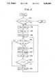
- step S10After it is confirmed in step S10 that the ignition switch has been turned on, control passes to steps S12, S14 in which the alcohol concentration VALC and the engine coolant temperature Tw are read. Control then advances to step S16 in which the read-in values are used as address data for retrieving a heater on-time tH from a map, whereby the heater on-time tH is determined. Next, having confirmed at step S18 that the vehicle speed is below 15 km/h, control moves to step S20 in which the alcohol concentration VALC and engine coolant temperature Tw are again used as address data for retrieving the amount of current (current level) IH to be supplied to the heater 32 from a second map, whereby the heater current level IH is determined.
- FIGS. 4 and 5illustrate the characteristics of the maps referred above.
- the heater on-time tHis predetermined such that it decreases with increasing engine temperature, i.e. engine coolant temperature Tw and also decreases with increasing alcohol concentration VALC.
- the amount of current IH to be supplied to the heaterincreases with increasing alcohol concentration VALC and decreases with increasing engine coolant temperature Tw.
- the "map"means look-up table(s) to be retrieved by two parameters, while a "table” a look-up table to be retrieved by a single parameter.
- step S26If the heater-on time tH is found, at step S26, to be zero or less, control passes to step S28 in which supply of current to the heater 32 is discontinued.
- the outputs of the alcohol sensor 26 and the coolant temperature sensor 46namely the alcohol concentration VALC and the engine coolant temperature Tw, are again read and the same procedure is repeated.
- the ECU 36continues to output control signals for controlling the supply of current to the heater 32 for as long as the ignition switch is on.
- control by the ECU 36is discontinued.
- supply of current to the heater 32 at the current level IHis continued until the originally decided heater on-time tH has lapsed.
- blended alcohol-gasoline fuelis supplied from the fuel tank 22 to the fuel injector 20 which injects it toward the combustion chamber 12 of the main engine unit 10.
- the injected fuelmixes with the air being introduced through the intake manifold to form an air-fuel mixture that is introduced into the combustion chamber 12 of the main engine unit 10.
- the air-fuel mixtureis compressed by a piston.
- a high voltageis applied across the electrodes 30a, 30b of the spark plug 30.
- the resulting spark dischargeignites the air-fuel mixture in the combustion chamber 12, causing it to burn explosively and drive down the piston.
- the temperature in the vicinity of the spark plug 30 in the combustion chamber 12is low.
- the present systemeliminates this problem.
- the alcohol concentration of the blended fuel being supplied to the combustion chamber 12is detected by the alcohol sensor 26 and the engine temperature is detected by the coolant temperature sensor 46. If it is found that the alcohol concentration is high and the engine temperature low, i.e. if the condition is one in which liquid alcohol is apt to adhere to the electrodes 30a, 30b of the spark plug 30, the ECU 36 supplies a large current to the heater 32 mounted on the spark plug 30. The heater 32 therefore produces a large amount of heat, which raises the temperature of the spark plug electrodes 30a, 30b to a high level. As a result, any liquid alcohol adhering to the electrodes 30a, 30b is immediately vaporized. The high electrical insulation between the electrodes 30a,30b can therefore be maintained.
- the system according to this embodimentis able to prevent liquid alcohol from adhering between the electrodes 30a, 30b of the spark plug 30. As this makes it possible to use a blended fuel with a high alcohol concentration even during the winter, it enables a reduction in gasoline consumption.
- the time period for which heating of the spark plug 30 has to be continued for vaporizing liquid alcohol adhering between the electrodesis short, the period of time over which current has to be supplied to the heater 32 is also short. Since this means that a large current need be supplied only for a short period, the amount of electric power consumed by the heater 32 can be kept to a low level.
- the ECU 36responds to the increasing engine temperature by selecting the optimum current level for the engine supplied to the heater 32. It also shortens the heater on-time. The amount of power consumed by the heater 32 is therefore minimized.
- the on-time of the heater 32is varied in proportion to the alcohol content of the blended fuel, this is not absolutely necessary and, in some cases, it is possible to set a fixed heater on-time.
- FIG. 6is the flow chart of a subroutine for calculating the correction coefficient Kd.
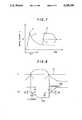
- the resistance of the heater 32is normally relatively low at the beginning and increases as the temperature of the heater 32 rises owing to the passage of current therethrough.
- the spark plug 30becomes wet with fuel, its resistance decreases because its temperature falls owing to heat lost to the adhering fuel.
- FIG. 7shows the change in current through the heater 32 under application of a fixed voltage. When current first starts to flow, it rises to a high level peaked at "a" because the resistance is low. Then as the resistance increases, the current decreases as illustrated by a dashed line.
- the coefficient Kdis first increased by delta P and is then progressively increased by increments of delta Q at each time interval (tm2 ⁇ N2) until it reaches the upper limit value of KdH.
- Another time period tm1is prepared for masking the initial high level peaked at "a" which is not caused by the plug's wetting.
- step S100 of the flow chartthe coolant temperature Tw is compared with a prescribed value Tws (-20° C., for example). If coolant temperature Tw is at or below the prescribed value Tws, control passes to step S102 in which it is checked if a high-load increased fuel injection flag Fwot (which is set to one when the amount of fuel injected is increased under high load) is set to zero and, if the result is affirmative, to step S104 in which the engine speed Ne is compared with a prescribed value Nes (400 rpm, for example).
- Fwotwhich is set to one when the amount of fuel injected is increased under high load
- step S110in which the heater 32 is turned on
- step S112in which the time value tm2 (10 sec., for example) is set to a second countdown timer to start countdown
- step S114in which the coefficient Kd is set to 1
- step S116in which the time value tm1 (0.8 msec., for example) is set to the first countdown timer to start countdown
- step S118in which the injection amount Tout is determined as illustrated (no reduction is made at this stage) and the program is once terminated.
- Ffcwhich is set to one when the supply of fuel is cutoff as when, for example, the engine braking is being used
- step S124it is checked if the detected current value I crosses the reference value Is and if it does, control passes to step S126 in which the count values N1, N2 (both 4, for example) are set to first and second counters, to step S128 in which it is checked if the current value I is at or below the reference value Is. If the current value I is found to be larger than the reference value Is, control passes to step S130 in which the coefficient Kd is updated to the value obtained by subtracting the prescribed value delta P from the value of Kd in the preceding cycle.
- step S142If it is found in step S124 that the detected current values I does not cross the reference value Is, control passes step S142 in which it is checked if the detected current value I is at or below the reference value Is. If the current value I is found to be larger than the reference value Is, control passes to step S144 in which the count value N1 of the first counter is decremented by one, to step S146 in which it is checked if the value N1 has become zero and, if it does, to step S148 in which the coefficient Kd is updated to the value obtained by subtracting the prescribed value delta Q (delta Q ⁇ delta P) from the value of Kd in the preceding cycle, and then to step S150 in which the value N1 is again set to the counter, and to step S134 and thereafter. If the value N1 is found to be not zero at step S146, control skips S148, S150.
- step S142If it is found in step S142 that the current value I is at or less than the reference value Is, control passes to step S152 in which the count value N2 of the second counter is decremented by one, to step S154 in which it is checked if the value N2 has reached zero and, if so, to step S156 in which the coefficient Kd is updated to the value obtained by adding the prescribed value of delta Q to the value of Kd in the preceding cycle, and then to step S158 in which the value N2 is again set to the counter, and to step S134 and thereafter. If the value N2 is found to be not zero at step S154, control jumps to step S134.
- step S100 or S104when it is found at step S100 or S104 that when Tw is greater than Tws or Ne is greater than Nes, there is no danger of the spark plug 30 being wetted. And if it is found in step S102 that the flag Fwot being set to one indicates that an increased amount of fuel is being supplied for raising the power output and that combustion is stable, namely a situation in which the amount of fuel supply should not be reduced. In these cases, therefore, control passes to step S162 in which the coefficient Kd is set to 1 so that no reduction of fuel supply is carried out. This is the same when the fuel cut flag is found to be set to one at step S122 so that control moves to step S164.
- FIG. 9is the subroutine flow chart showing the control of supplying the current to the heater 32 mentioned earlier.
- Japanese Patent Publication No. 48(1983)-8651teaches that the starting performance of an engine can be improved by mounting heater on the engine's spark plugs and turning on the heater to warm the spark plug tip when the ignition switch is turned on.
- the heateris turned on when the ignition switch is turned and remain on even after the starter switch is turned on.
- the starter switchis turned on, a large amount of power is suddenly required to operate the starter motor Because of this, if, as in arrangement described in the aforesaid prior art, the heater is left on even after the starter switch is turned on, there may be insufficient power available to operate the starter motor.
- the control illustrated in FIG. 9enables the starter motor to be supplied with sufficient electric power for its operation when the starter switch is turned on, for the engine, in particular, using the gasoline-alcohol blend fuel.
- step S200the alcohol concentration VALC is compared with a prescribed value VALCs (60%, for example). If the alcohol concentration VALC is found to be greater than the value VALCs, control passes to step S202 in which the coolant temperature Tw is compared with a prescribed value Tws (-20 ° C., for example). If the coolant temperature Tw is found to be at or below the value Tws, control passes to step S204 in which it is checked if the engine is in the starting (cranking) mode. Before an engine has started i.e.
- step S206an after-heating countdown timer is set to a time period tmAF retrieved from a map to be explained later to start countdown, and then to step S208 in which it is checked if the starter switch is on.
- step S210another countdown timer for determining the period during which the heater is to be turned off following turn-on of the starter switch is set to a prescribed value tmD to start countdown and then passes to step S212 in which it is checked if a timer check flag F is set to 1.
- step S220when the time tmPR is found to have become zero in step S220, control passes to step S226 in which it is checked if the time tmPRF, which is repeatedly restarted each time control passes step S222, has become zero. Following the time at which tmPR becomes zero but during the lapse of the time to which the time tmPRF becomes zero, control passes to step S228 in which the time value tmWT is set to the countdown counter to start countdown and to step S230 in which the heater 32 is turned off.
- step S226When it is found in step S226 that the time tmPRF has become zero, control passes to step S232 in which it is checked if the time tmWT has become zero. Following the time at which tmPRF becomes zero but during the time tmWT becomes zero, control passes to step S224 to keep the heater 32 on. After the time value tmWT has become zero, control passes to step S230 to turn the heater 32 off.
- the heater 32is turned on for the time tmPR. As a result, the temperature of the heater 32 rises high enough to vaporize the fuel. Although the operator turns on the starter switch shortly after the heater 32 is turned on, so long as the starter switch is still in the off position, once the time to which tmPRF was set has lapsed, the heater 32 is again turned on for the time to which the tmWT is set.
- step S208When the starter switch has been turned on, control passes from step S208 to step S234, whereby the flag F is set to zero, and, following this, to step S236 in which it is checked if the time value tmD is zero.
- step S210i.e, just before the starter switch is turned on so that the time tmD is not zero between the point in time at which the starter is turned on and the point in time at which the set period of time lapses.
- step S230in which the heater is turned off and then, when the it is found in step S236 that time value tmD has become zero, passes to step S224, via step S222, for turning on the heater 32.
- step S204control passes from step S204 to step S238 in which it is checked if the time tmAF has lapsed.
- the coefficient Kdis decreased for reducing the amount of fuel supplied when the current value I is above the reference value Is, it is alternatively possible to use an arrangement in which the coefficient Kd is made zero for cutting off the supply of fuel at such times.
- the engineuses a gosoline-alcohol blend fuel, it can also be applied to an engine using a neat gasoline fuel to improve its startability.
Landscapes
- Engineering & Computer Science (AREA)
- Chemical & Material Sciences (AREA)
- Combustion & Propulsion (AREA)
- Mechanical Engineering (AREA)
- General Engineering & Computer Science (AREA)
- Output Control And Ontrol Of Special Type Engine (AREA)
- Electrical Control Of Air Or Fuel Supplied To Internal-Combustion Engine (AREA)
Abstract
Description
Claims (22)
Applications Claiming Priority (6)
| Application Number | Priority Date | Filing Date | Title |
|---|---|---|---|
| JP3-321558 | 1991-11-11 | ||
| JP32155891AJP2577674B2 (en) | 1991-11-11 | 1991-11-11 | Engine ignition device |
| JP3-339258 | 1991-12-24 | ||
| JP33925891AJP2932118B2 (en) | 1991-12-24 | 1991-12-24 | Engine fuel supply control device |
| JP34287291AJPH05172027A (en) | 1991-12-25 | 1991-12-25 | Power supply control device for ignition plug heater |
| JP3-342872 | 1991-12-25 |
Publications (1)
| Publication Number | Publication Date |
|---|---|
| US5230309Atrue US5230309A (en) | 1993-07-27 |
Family
ID=27339863
Family Applications (1)
| Application Number | Title | Priority Date | Filing Date |
|---|---|---|---|
| US07/974,024Expired - LifetimeUS5230309A (en) | 1991-11-11 | 1992-11-10 | Spark plug heater control system for internal combustion engine |
Country Status (1)
| Country | Link |
|---|---|
| US (1) | US5230309A (en) |
Cited By (42)
| Publication number | Priority date | Publication date | Assignee | Title |
|---|---|---|---|---|
| EP1138940A3 (en)* | 2000-03-29 | 2005-04-13 | Ngk Spark Plug Co., Ltd. | Control system for an internal combustion engine and method carried out by the same |
| US20070119391A1 (en)* | 2005-11-30 | 2007-05-31 | Marcus Fried | Control for alcohol/water/gasoline injection |
| US20070119421A1 (en)* | 2005-11-30 | 2007-05-31 | Lewis Donald J | System and method for compensation of fuel injector limits |
| US20070119415A1 (en)* | 2005-11-30 | 2007-05-31 | Lewis Donald J | System and method for engine air-fuel ratio control |
| US20070119412A1 (en)* | 2005-11-30 | 2007-05-31 | Leone Thomas G | Engine with two port fuel injectors |
| US20070119416A1 (en)* | 2005-11-30 | 2007-05-31 | Boyarski Nicholas J | System for fuel vapor purging |
| US20070119394A1 (en)* | 2005-11-30 | 2007-05-31 | Leone Thomas G | Fuel mass control for ethanol direct injection plus gasoline port fuel injection |
| US20070119413A1 (en)* | 2005-11-30 | 2007-05-31 | Lewis Donald J | Event based engine control system and method |
| US7255080B1 (en)* | 2006-03-17 | 2007-08-14 | Ford Global Technologies, Llc | Spark plug heating for a spark ignited engine |
| US20070215130A1 (en)* | 2006-03-17 | 2007-09-20 | Michael Shelby | Spark control for improved engine operation |
| US20070215102A1 (en)* | 2006-03-17 | 2007-09-20 | Russell John D | First and second spark plugs for improved combustion control |
| US20070215111A1 (en)* | 2006-03-17 | 2007-09-20 | Gopichandra Surnilla | System and method for reducing knock and preignition in an internal combustion engine |
| US20070215072A1 (en)* | 2006-03-17 | 2007-09-20 | Mark Dearth | Apparatus with mixed fuel separator and method of separating a mixed fuel |
| US20070215104A1 (en)* | 2006-03-17 | 2007-09-20 | Stephen Hahn | Combustion control system for an engine utilizing a first fuel and a second fuel |
| US20070215101A1 (en)* | 2006-03-17 | 2007-09-20 | Russell John D | First and second spark plugs for improved combustion control |
| US20070215069A1 (en)* | 2006-03-17 | 2007-09-20 | Leone Thomas G | Control for knock suppression fluid separator in a motor vehicle |
| US20070215071A1 (en)* | 2006-03-17 | 2007-09-20 | Mark Dearth | Apparatus with mixed fuel separator and method of separating a mixed fuel |
| US20070219674A1 (en)* | 2006-03-17 | 2007-09-20 | Leone Thomas G | Control of peak engine output in an engine with a knock suppression fluid |
| US20070289573A1 (en)* | 2005-11-30 | 2007-12-20 | Ford Global Technologies, Llc | Warm Up Strategy for Ethanol Direct Injection Plus Gasoline Port Fuel Injection |
| US20070295307A1 (en)* | 2005-11-30 | 2007-12-27 | Ford Global Technologies, Llc | System and Method for Engine with Fuel Vapor Purging |
| US20080017171A1 (en)* | 2006-07-24 | 2008-01-24 | Ford Global Technologies, Llc | Approach for Reducing Injector Fouling and Thermal Degradation for a Multi-Injector Engine System |
| US20080035106A1 (en)* | 2006-08-11 | 2008-02-14 | Stein Robert A | Direct Injection Alcohol Engine with Boost and Spark Control |
| US7406947B2 (en) | 2005-11-30 | 2008-08-05 | Ford Global Technologies, Llc | System and method for tip-in knock compensation |
| US7412966B2 (en) | 2005-11-30 | 2008-08-19 | Ford Global Technologies, Llc | Engine output control system and method |
| US7426908B2 (en) | 2006-08-11 | 2008-09-23 | Ford Global Technologies, Llc | Direct injection alcohol engine with variable injection timing |
| US7428895B2 (en) | 2005-11-30 | 2008-09-30 | Ford Global Technologies, Llc | Purge system for ethanol direct injection plus gas port fuel injection |
| US20080288158A1 (en)* | 2006-03-17 | 2008-11-20 | Ford Global Technologies, Llc | Control for knock suppression fluid separator in a motor vehicle |
| US7461628B2 (en) | 2006-12-01 | 2008-12-09 | Ford Global Technologies, Llc | Multiple combustion mode engine using direct alcohol injection |
| US20090038586A1 (en)* | 2007-08-10 | 2009-02-12 | Ford Global Technologies, Llc | Hybrid Vehicle Propulsion System Utilizing Knock Suppression |
| US20090157277A1 (en)* | 2007-12-12 | 2009-06-18 | Ford Global Technologies, Llc | On-Board Fuel Vapor Separation for Multi-Fuel Vehicle |
| US20090178654A1 (en)* | 2008-01-16 | 2009-07-16 | Ford Global Technologies, Llc | Ethanol Separation Using Air from Turbo Compressor |
| US7581528B2 (en) | 2006-03-17 | 2009-09-01 | Ford Global Technologies, Llc | Control strategy for engine employng multiple injection types |
| US7665428B2 (en) | 2006-03-17 | 2010-02-23 | Ford Global Technologies, Llc | Apparatus with mixed fuel separator and method of separating a mixed fuel |
| US7730872B2 (en) | 2005-11-30 | 2010-06-08 | Ford Global Technologies, Llc | Engine with water and/or ethanol direct injection plus gas port fuel injectors |
| US7845315B2 (en) | 2008-05-08 | 2010-12-07 | Ford Global Technologies, Llc | On-board water addition for fuel separation system |
| US7971567B2 (en) | 2007-10-12 | 2011-07-05 | Ford Global Technologies, Llc | Directly injected internal combustion engine system |
| US8214130B2 (en) | 2007-08-10 | 2012-07-03 | Ford Global Technologies, Llc | Hybrid vehicle propulsion system utilizing knock suppression |
| US8550058B2 (en) | 2007-12-21 | 2013-10-08 | Ford Global Technologies, Llc | Fuel rail assembly including fuel separation membrane |
| CN110005564A (en)* | 2018-01-05 | 2019-07-12 | 福特全球技术公司 | Method and system for engine control |
| US11359594B2 (en)* | 2018-05-23 | 2022-06-14 | Hitachi Astemo, Ltd. | Internal combustion engine control device |
| US20220349359A1 (en)* | 2020-02-26 | 2022-11-03 | Clearflame Engines, Inc. | Fuel agnostic compression ignition engine |
| US11536239B2 (en) | 2019-05-21 | 2022-12-27 | Cummins Inc. | Variable energy ignition systems, methods, and apparatuses |
Citations (10)
| Publication number | Priority date | Publication date | Assignee | Title |
|---|---|---|---|---|
| US1805040A (en)* | 1928-01-10 | 1931-05-12 | Groves Cecil Reginald Downer | Electrical warming means or device for use with internal combustion engines to facilitate starting thereof |
| US2048481A (en)* | 1935-09-12 | 1936-07-21 | Arnois Charles Lennig | Spark plug |
| JPS498651A (en)* | 1972-05-26 | 1974-01-25 | ||
| US3868939A (en)* | 1972-03-03 | 1975-03-04 | Bosch Gmbh Robert | Fuel injection system especially for cold starting and warming up externally ignited internal combustion engines |
| US4205650A (en)* | 1978-05-15 | 1980-06-03 | Szymon Szwarcbier | Start aid for combustion engine |
| US4387676A (en)* | 1980-09-04 | 1983-06-14 | General Motors Corporation | Cold starting system for alcohol fueled engine |
| US4433665A (en)* | 1981-03-23 | 1984-02-28 | Nippon Soken, Inc. | Device for controlling choke valve in carburetor for internal combustion engine |
| JPS6042291A (en)* | 1983-08-18 | 1985-03-06 | Furukawa Electric Co Ltd:The | Method and device for growing gallium arsenide single crystal |
| US4870932A (en)* | 1988-11-21 | 1989-10-03 | Chrysler Motors Corporation | Fuel injection heating system |
| US5044331A (en)* | 1989-12-28 | 1991-09-03 | Honda Motor Co., Ltd. | Air-fuel ratio control method for an internal combustion engine having spark plugs with heaters |
- 1992
- 1992-11-10USUS07/974,024patent/US5230309A/ennot_activeExpired - Lifetime
Patent Citations (10)
| Publication number | Priority date | Publication date | Assignee | Title |
|---|---|---|---|---|
| US1805040A (en)* | 1928-01-10 | 1931-05-12 | Groves Cecil Reginald Downer | Electrical warming means or device for use with internal combustion engines to facilitate starting thereof |
| US2048481A (en)* | 1935-09-12 | 1936-07-21 | Arnois Charles Lennig | Spark plug |
| US3868939A (en)* | 1972-03-03 | 1975-03-04 | Bosch Gmbh Robert | Fuel injection system especially for cold starting and warming up externally ignited internal combustion engines |
| JPS498651A (en)* | 1972-05-26 | 1974-01-25 | ||
| US4205650A (en)* | 1978-05-15 | 1980-06-03 | Szymon Szwarcbier | Start aid for combustion engine |
| US4387676A (en)* | 1980-09-04 | 1983-06-14 | General Motors Corporation | Cold starting system for alcohol fueled engine |
| US4433665A (en)* | 1981-03-23 | 1984-02-28 | Nippon Soken, Inc. | Device for controlling choke valve in carburetor for internal combustion engine |
| JPS6042291A (en)* | 1983-08-18 | 1985-03-06 | Furukawa Electric Co Ltd:The | Method and device for growing gallium arsenide single crystal |
| US4870932A (en)* | 1988-11-21 | 1989-10-03 | Chrysler Motors Corporation | Fuel injection heating system |
| US5044331A (en)* | 1989-12-28 | 1991-09-03 | Honda Motor Co., Ltd. | Air-fuel ratio control method for an internal combustion engine having spark plugs with heaters |
Cited By (93)
| Publication number | Priority date | Publication date | Assignee | Title |
|---|---|---|---|---|
| EP1138940A3 (en)* | 2000-03-29 | 2005-04-13 | Ngk Spark Plug Co., Ltd. | Control system for an internal combustion engine and method carried out by the same |
| US7694666B2 (en) | 2005-11-30 | 2010-04-13 | Ford Global Technologies, Llc | System and method for tip-in knock compensation |
| US7584740B2 (en) | 2005-11-30 | 2009-09-08 | Ford Global Technologies, Llc | Engine system for multi-fluid operation |
| US20070119415A1 (en)* | 2005-11-30 | 2007-05-31 | Lewis Donald J | System and method for engine air-fuel ratio control |
| US20070119412A1 (en)* | 2005-11-30 | 2007-05-31 | Leone Thomas G | Engine with two port fuel injectors |
| US20070119416A1 (en)* | 2005-11-30 | 2007-05-31 | Boyarski Nicholas J | System for fuel vapor purging |
| US20070119394A1 (en)* | 2005-11-30 | 2007-05-31 | Leone Thomas G | Fuel mass control for ethanol direct injection plus gasoline port fuel injection |
| US20070119413A1 (en)* | 2005-11-30 | 2007-05-31 | Lewis Donald J | Event based engine control system and method |
| US8434431B2 (en) | 2005-11-30 | 2013-05-07 | Ford Global Technologies, Llc | Control for alcohol/water/gasoline injection |
| US8393312B2 (en) | 2005-11-30 | 2013-03-12 | Ford Global Technologies, Llc | Event based engine control system and method |
| US8132555B2 (en) | 2005-11-30 | 2012-03-13 | Ford Global Technologies, Llc | Event based engine control system and method |
| US7877189B2 (en) | 2005-11-30 | 2011-01-25 | Ford Global Technologies, Llc | Fuel mass control for ethanol direct injection plus gasoline port fuel injection |
| US7730872B2 (en) | 2005-11-30 | 2010-06-08 | Ford Global Technologies, Llc | Engine with water and/or ethanol direct injection plus gas port fuel injectors |
| US7721710B2 (en) | 2005-11-30 | 2010-05-25 | Ford Global Technologies, Llc | Warm up strategy for ethanol direct injection plus gasoline port fuel injection |
| US7426925B2 (en) | 2005-11-30 | 2008-09-23 | Ford Global Technologies, Llc | Warm up strategy for ethanol direct injection plus gasoline port fuel injection |
| US20070119421A1 (en)* | 2005-11-30 | 2007-05-31 | Lewis Donald J | System and method for compensation of fuel injector limits |
| US7647916B2 (en) | 2005-11-30 | 2010-01-19 | Ford Global Technologies, Llc | Engine with two port fuel injectors |
| US7357101B2 (en) | 2005-11-30 | 2008-04-15 | Ford Global Technologies, Llc | Engine system for multi-fluid operation |
| US7594498B2 (en) | 2005-11-30 | 2009-09-29 | Ford Global Technologies, Llc | System and method for compensation of fuel injector limits |
| US20070289573A1 (en)* | 2005-11-30 | 2007-12-20 | Ford Global Technologies, Llc | Warm Up Strategy for Ethanol Direct Injection Plus Gasoline Port Fuel Injection |
| US20070295307A1 (en)* | 2005-11-30 | 2007-12-27 | Ford Global Technologies, Llc | System and Method for Engine with Fuel Vapor Purging |
| US7640914B2 (en) | 2005-11-30 | 2010-01-05 | Ford Global Technologies, Llc | Engine output control system and method |
| US20090070021A1 (en)* | 2005-11-30 | 2009-03-12 | Ford Global Technologies, Llc | Warm Up Strategy for Ethanol Direct Injection Plus Gasoline Port Fuel Injection |
| US7640912B2 (en) | 2005-11-30 | 2010-01-05 | Ford Global Technologies, Llc | System and method for engine air-fuel ratio control |
| US20070119391A1 (en)* | 2005-11-30 | 2007-05-31 | Marcus Fried | Control for alcohol/water/gasoline injection |
| US7406947B2 (en) | 2005-11-30 | 2008-08-05 | Ford Global Technologies, Llc | System and method for tip-in knock compensation |
| US7412966B2 (en) | 2005-11-30 | 2008-08-19 | Ford Global Technologies, Llc | Engine output control system and method |
| US20080210207A1 (en)* | 2005-11-30 | 2008-09-04 | Ford Global Technologies, Llc | Engine System for Multi-Fluid Operation |
| US7424881B2 (en) | 2005-11-30 | 2008-09-16 | Ford Global Technologies, Llc | System and method for engine with fuel vapor purging |
| US20080228382A1 (en)* | 2005-11-30 | 2008-09-18 | Ford Global Technologies, Llc | Engine output control system and method |
| US7428895B2 (en) | 2005-11-30 | 2008-09-30 | Ford Global Technologies, Llc | Purge system for ethanol direct injection plus gas port fuel injection |
| US7389751B2 (en) | 2006-03-17 | 2008-06-24 | Ford Global Technology, Llc | Control for knock suppression fluid separator in a motor vehicle |
| US8015951B2 (en) | 2006-03-17 | 2011-09-13 | Ford Global Technologies, Llc | Apparatus with mixed fuel separator and method of separating a mixed fuel |
| US7426907B2 (en) | 2006-03-17 | 2008-09-23 | Ford Global Technologies, Llc | Apparatus with mixed fuel separator and method of separating a mixed fuel |
| US20080288158A1 (en)* | 2006-03-17 | 2008-11-20 | Ford Global Technologies, Llc | Control for knock suppression fluid separator in a motor vehicle |
| US7255080B1 (en)* | 2006-03-17 | 2007-08-14 | Ford Global Technologies, Llc | Spark plug heating for a spark ignited engine |
| US20070215130A1 (en)* | 2006-03-17 | 2007-09-20 | Michael Shelby | Spark control for improved engine operation |
| US8267074B2 (en) | 2006-03-17 | 2012-09-18 | Ford Global Technologies, Llc | Control for knock suppression fluid separator in a motor vehicle |
| US7533651B2 (en) | 2006-03-17 | 2009-05-19 | Ford Global Technologies, Llc | System and method for reducing knock and preignition in an internal combustion engine |
| CN101037968B (en)* | 2006-03-17 | 2012-08-15 | 福特环球技术公司 | First and second spark plugs for improved combustion control |
| US20070215102A1 (en)* | 2006-03-17 | 2007-09-20 | Russell John D | First and second spark plugs for improved combustion control |
| US7578281B2 (en) | 2006-03-17 | 2009-08-25 | Ford Global Technologies, Llc | First and second spark plugs for improved combustion control |
| US7581528B2 (en) | 2006-03-17 | 2009-09-01 | Ford Global Technologies, Llc | Control strategy for engine employng multiple injection types |
| US7933713B2 (en) | 2006-03-17 | 2011-04-26 | Ford Global Technologies, Llc | Control of peak engine output in an engine with a knock suppression fluid |
| US20070234976A1 (en)* | 2006-03-17 | 2007-10-11 | Mark Dearth | Apparatus with Mixed Fuel Separator and Method of Separating a Mixed Fuel |
| US20070219674A1 (en)* | 2006-03-17 | 2007-09-20 | Leone Thomas G | Control of peak engine output in an engine with a knock suppression fluid |
| US20070215071A1 (en)* | 2006-03-17 | 2007-09-20 | Mark Dearth | Apparatus with mixed fuel separator and method of separating a mixed fuel |
| US7647899B2 (en) | 2006-03-17 | 2010-01-19 | Ford Global Technologies, Llc | Apparatus with mixed fuel separator and method of separating a mixed fuel |
| US20070215069A1 (en)* | 2006-03-17 | 2007-09-20 | Leone Thomas G | Control for knock suppression fluid separator in a motor vehicle |
| US7665428B2 (en) | 2006-03-17 | 2010-02-23 | Ford Global Technologies, Llc | Apparatus with mixed fuel separator and method of separating a mixed fuel |
| US7665452B2 (en) | 2006-03-17 | 2010-02-23 | Ford Global Technologies, Llc | First and second spark plugs for improved combustion control |
| US20070215111A1 (en)* | 2006-03-17 | 2007-09-20 | Gopichandra Surnilla | System and method for reducing knock and preignition in an internal combustion engine |
| US7779813B2 (en) | 2006-03-17 | 2010-08-24 | Ford Global Technologies, Llc | Combustion control system for an engine utilizing a first fuel and a second fuel |
| US20070215101A1 (en)* | 2006-03-17 | 2007-09-20 | Russell John D | First and second spark plugs for improved combustion control |
| US20070215104A1 (en)* | 2006-03-17 | 2007-09-20 | Stephen Hahn | Combustion control system for an engine utilizing a first fuel and a second fuel |
| US20070215072A1 (en)* | 2006-03-17 | 2007-09-20 | Mark Dearth | Apparatus with mixed fuel separator and method of separating a mixed fuel |
| US7740009B2 (en) | 2006-03-17 | 2010-06-22 | Ford Global Technologies, Llc | Spark control for improved engine operation |
| US20080017171A1 (en)* | 2006-07-24 | 2008-01-24 | Ford Global Technologies, Llc | Approach for Reducing Injector Fouling and Thermal Degradation for a Multi-Injector Engine System |
| US7681554B2 (en) | 2006-07-24 | 2010-03-23 | Ford Global Technologies, Llc | Approach for reducing injector fouling and thermal degradation for a multi-injector engine system |
| US8245690B2 (en) | 2006-08-11 | 2012-08-21 | Ford Global Technologies, Llc | Direct injection alcohol engine with boost and spark control |
| US7909019B2 (en) | 2006-08-11 | 2011-03-22 | Ford Global Technologies, Llc | Direct injection alcohol engine with boost and spark control |
| US7426908B2 (en) | 2006-08-11 | 2008-09-23 | Ford Global Technologies, Llc | Direct injection alcohol engine with variable injection timing |
| US20080035106A1 (en)* | 2006-08-11 | 2008-02-14 | Stein Robert A | Direct Injection Alcohol Engine with Boost and Spark Control |
| US7461628B2 (en) | 2006-12-01 | 2008-12-09 | Ford Global Technologies, Llc | Multiple combustion mode engine using direct alcohol injection |
| US8453627B2 (en) | 2007-08-10 | 2013-06-04 | Ford Global Technologies, Llc | Hybrid vehicle propulsion system utilizing knock suppression |
| US7676321B2 (en) | 2007-08-10 | 2010-03-09 | Ford Global Technologies, Llc | Hybrid vehicle propulsion system utilizing knock suppression |
| US20090038586A1 (en)* | 2007-08-10 | 2009-02-12 | Ford Global Technologies, Llc | Hybrid Vehicle Propulsion System Utilizing Knock Suppression |
| US8733330B2 (en) | 2007-08-10 | 2014-05-27 | Ford Global Technologies, Llc | Hybrid vehicle propulsion system utilizing knock suppression |
| US8214130B2 (en) | 2007-08-10 | 2012-07-03 | Ford Global Technologies, Llc | Hybrid vehicle propulsion system utilizing knock suppression |
| US7971567B2 (en) | 2007-10-12 | 2011-07-05 | Ford Global Technologies, Llc | Directly injected internal combustion engine system |
| US8235024B2 (en) | 2007-10-12 | 2012-08-07 | Ford Global Technologies, Llc | Directly injected internal combustion engine system |
| US8495983B2 (en) | 2007-10-12 | 2013-07-30 | Ford Global Technologies, Llc | Directly injected internal combustion engine system |
| US20090157277A1 (en)* | 2007-12-12 | 2009-06-18 | Ford Global Technologies, Llc | On-Board Fuel Vapor Separation for Multi-Fuel Vehicle |
| US8312867B2 (en) | 2007-12-12 | 2012-11-20 | Ford Global Technologies, Llc | On-board fuel vapor separation for multi-fuel vehicle |
| US8118009B2 (en) | 2007-12-12 | 2012-02-21 | Ford Global Technologies, Llc | On-board fuel vapor separation for multi-fuel vehicle |
| US8459238B2 (en) | 2007-12-12 | 2013-06-11 | Ford Global Technologies, Llc | On-board fuel vapor separation for multi-fuel vehicle |
| US8550058B2 (en) | 2007-12-21 | 2013-10-08 | Ford Global Technologies, Llc | Fuel rail assembly including fuel separation membrane |
| US9038613B2 (en) | 2007-12-21 | 2015-05-26 | Ford Global Technologies, Llc | Fuel rail assembly including fuel separation membrane |
| US8141356B2 (en) | 2008-01-16 | 2012-03-27 | Ford Global Technologies, Llc | Ethanol separation using air from turbo compressor |
| US20090178654A1 (en)* | 2008-01-16 | 2009-07-16 | Ford Global Technologies, Llc | Ethanol Separation Using Air from Turbo Compressor |
| US8375899B2 (en) | 2008-05-08 | 2013-02-19 | Ford Global Technologies, Llc | On-board water addition for fuel separation system |
| US8656869B2 (en) | 2008-05-08 | 2014-02-25 | Ford Global Technologies, Llc | On-board water addition for fuel separation system |
| US7845315B2 (en) | 2008-05-08 | 2010-12-07 | Ford Global Technologies, Llc | On-board water addition for fuel separation system |
| CN110005564A (en)* | 2018-01-05 | 2019-07-12 | 福特全球技术公司 | Method and system for engine control |
| CN110005564B (en)* | 2018-01-05 | 2025-09-19 | 福特全球技术公司 | Method and system for engine control |
| US11359594B2 (en)* | 2018-05-23 | 2022-06-14 | Hitachi Astemo, Ltd. | Internal combustion engine control device |
| US11840996B2 (en) | 2019-05-21 | 2023-12-12 | Cummins Inc. | Variable energy ignition systems, methods, and apparatuses |
| US11536239B2 (en) | 2019-05-21 | 2022-12-27 | Cummins Inc. | Variable energy ignition systems, methods, and apparatuses |
| US20230258143A1 (en)* | 2020-02-26 | 2023-08-17 | Clearflame Engines, Inc. | Full agnostic compression ignition engine |
| US11952954B2 (en) | 2020-02-26 | 2024-04-09 | Clearflame Engines, Inc. | Fuel agnostic compression ignition engine |
| US11959434B2 (en)* | 2020-02-26 | 2024-04-16 | Clearflame Engines, Inc. | Fuel agnostic compression ignition engine |
| US11976606B2 (en)* | 2020-02-26 | 2024-05-07 | Clearflame Engines, Inc. | Full agnostic compression ignition engine |
| US20220349359A1 (en)* | 2020-02-26 | 2022-11-03 | Clearflame Engines, Inc. | Fuel agnostic compression ignition engine |
Similar Documents
| Publication | Publication Date | Title |
|---|---|---|
| US5230309A (en) | Spark plug heater control system for internal combustion engine | |
| JP2857660B2 (en) | Air-fuel ratio control method for internal combustion engine having spark plug with heater | |
| KR100881877B1 (en) | Control apparatus for internal combustion engine | |
| US4995367A (en) | System and method of control of internal combustion engine using methane fuel mixture | |
| KR100916737B1 (en) | Control device of internal combustion engine | |
| EP1505293A1 (en) | Fuel supply system and fuel supply method for in-cylinder direct fuel injection engine | |
| KR100898884B1 (en) | Control apparatus for internal combustion engine | |
| CN1989330B (en) | Control device for internal combustion engine | |
| CN112664366B (en) | Oil rail heating system and method and vehicle | |
| JP2001012286A (en) | Fuel injection control device for in-cylinder injection internal combustion engine | |
| JP3867508B2 (en) | Fuel supply device for internal combustion engine | |
| JPH0261612B2 (en) | ||
| JPH10274076A (en) | Cylinder injection type engine | |
| JPH0626414A (en) | Start control for engine for ffv | |
| JPWO2006027853A1 (en) | Engine control device | |
| JPH0626427A (en) | Start control of engine for ffv | |
| JPH0642417A (en) | Fuel heating control method for ffv engine | |
| JPH11148441A (en) | Fuel supply device for internal combustion engine | |
| JPH03117650A (en) | Starting device for engine | |
| JP2577674B2 (en) | Engine ignition device | |
| JP2022030578A (en) | Fuel heating device | |
| JP2543922B2 (en) | Diesel engine glow plug controller | |
| JPH0617656B2 (en) | Fuel supply device for alcohol blended fuel | |
| JPH06101608A (en) | Control method for ffv engine | |
| JP2855227B2 (en) | Fuel injection control device for lean-burn internal combustion engine |
Legal Events
| Date | Code | Title | Description |
|---|---|---|---|
| AS | Assignment | Owner name:HONDA GIKEN KOGYO KABUSHIKI KAISHA, JAPAN Free format text:ASSIGNMENT OF ASSIGNORS INTEREST.;ASSIGNORS:SUGA, TOSHIYUKI;KODAMA, HIROKI;KITAJIMA, SHINICHI;AND OTHERS;REEL/FRAME:006302/0180 Effective date:19920922 | |
| FEPP | Fee payment procedure | Free format text:PAYOR NUMBER ASSIGNED (ORIGINAL EVENT CODE: ASPN); ENTITY STATUS OF PATENT OWNER: LARGE ENTITY | |
| STCF | Information on status: patent grant | Free format text:PATENTED CASE | |
| FEPP | Fee payment procedure | Free format text:PAYOR NUMBER ASSIGNED (ORIGINAL EVENT CODE: ASPN); ENTITY STATUS OF PATENT OWNER: LARGE ENTITY Free format text:PAYER NUMBER DE-ASSIGNED (ORIGINAL EVENT CODE: RMPN); ENTITY STATUS OF PATENT OWNER: LARGE ENTITY | |
| FPAY | Fee payment | Year of fee payment:4 | |
| FEPP | Fee payment procedure | Free format text:PAYER NUMBER DE-ASSIGNED (ORIGINAL EVENT CODE: RMPN); ENTITY STATUS OF PATENT OWNER: LARGE ENTITY Free format text:PAYOR NUMBER ASSIGNED (ORIGINAL EVENT CODE: ASPN); ENTITY STATUS OF PATENT OWNER: LARGE ENTITY | |
| FPAY | Fee payment | Year of fee payment:8 | |
| FPAY | Fee payment | Year of fee payment:12 |