US5230031A - Barrier for a connector - Google Patents
Barrier for a connectorDownload PDFInfo
- Publication number
- US5230031A US5230031AUS07/887,986US88798692AUS5230031AUS 5230031 AUS5230031 AUS 5230031AUS 88798692 AUS88798692 AUS 88798692AUS 5230031 AUS5230031 AUS 5230031A
- Authority
- US
- United States
- Prior art keywords
- handle
- junction
- open ended
- sheath
- distal end
- Prior art date
- Legal status (The legal status is an assumption and is not a legal conclusion. Google has not performed a legal analysis and makes no representation as to the accuracy of the status listed.)
- Expired - Fee Related
Links
Images
Classifications
- G—PHYSICS
- G02—OPTICS
- G02B—OPTICAL ELEMENTS, SYSTEMS OR APPARATUS
- G02B6/00—Light guides; Structural details of arrangements comprising light guides and other optical elements, e.g. couplings
- G02B6/24—Coupling light guides
- G02B6/36—Mechanical coupling means
- G02B6/38—Mechanical coupling means having fibre to fibre mating means
- G02B6/3807—Dismountable connectors, i.e. comprising plugs
- G02B6/3833—Details of mounting fibres in ferrules; Assembly methods; Manufacture
- G02B6/3847—Details of mounting fibres in ferrules; Assembly methods; Manufacture with means preventing fibre end damage, e.g. recessed fibre surfaces
- G02B6/3849—Details of mounting fibres in ferrules; Assembly methods; Manufacture with means preventing fibre end damage, e.g. recessed fibre surfaces using mechanical protective elements, e.g. caps, hoods, sealing membranes
- G—PHYSICS
- G02—OPTICS
- G02B—OPTICAL ELEMENTS, SYSTEMS OR APPARATUS
- G02B6/00—Light guides; Structural details of arrangements comprising light guides and other optical elements, e.g. couplings
- G02B6/24—Coupling light guides
- G02B6/36—Mechanical coupling means
- G02B6/38—Mechanical coupling means having fibre to fibre mating means
- G02B6/3807—Dismountable connectors, i.e. comprising plugs
- G02B6/381—Dismountable connectors, i.e. comprising plugs of the ferrule type, e.g. fibre ends embedded in ferrules, connecting a pair of fibres
- G02B6/3816—Dismountable connectors, i.e. comprising plugs of the ferrule type, e.g. fibre ends embedded in ferrules, connecting a pair of fibres for use under water, high pressure connectors
Definitions
- This inventionrelates to a barrier for a connector and more particularly an elastic open ended sheath for the junction between an interengaging member and a conjugating part that are the components of the connector.
- Connectors to easily and repeatedly attach and disconnect conductors without tools or the to unfasten permanent connectionsare in use in many areas and applications.
- plugs and receptaclesare used in every home and business for electrical circuits.
- Conductors other than electricalare sometimes split with connectors, where required.
- Light transmission through a fiber opticmay need a simple coupling that can be attached and disconnected repeatedly without concern about the quality of the connection.
- Seals for weather proofing connectorsare a problem in many environments. With medical devices the need to keep connections made by a connector clean and free from dirt and fluids is particularly important since a human life could depend on the quality of the connection making able the transmission through the conductors connected thereby the required signal, energy or the like.
- a barrier for a junction between an interengaging member and a conjugating partpreferably has the interengaging member with a body which terminates in a distal end.
- the distal endmost preferably has pieces thereon for engaging and an edge thereabout.
- the barrieralso preferably has the conjugating part which has a handle reaching to a terminal face having a periphery thereabout and having features associated therewith for matingly engaging with the pieces on the distal end.
- the body or the handlemay have a proximal portion of reduced cross section which terminates in a centrally positioned shoulder facing proximally.
- a resilient sleevewhich has an internal passage shaped to snugly fit the proximal portion Of reduced cross section and an abutting end to abut the proximally facing shoulder for capture thereagainst.
- the interengaging member and the conjugating partform a connector when the distal end pieces engage the terminal face features mating at the junction therebetween.
- the connectorpreferably has a key and a keyway therebetween to prealign the distal end pieces and the terminal face features.
- the distal end pieces and the terminal face featurespreferably include conductors for electrical circuits and optical paths.
- the junctionwhich is formed about and between the interengaging member and the conjugating part when joined with the pieces and the features when fully united with the distal end of the body against the terminal face, preferably includes releasable locking means.
- the releasable locking meansare located for and accessible to movement when covered over by the elastic open ended sheath extended over the body to the handle or over the handle to the body thereby covering the junction so when covered it may be locked or released while protected within the elastic open ended sheath.
- the elastic open ended sheathwhen appended to the body or the handle, is capable of being extended over the body to the handle or over the handle to the body for covering the junction and is preferably gatherable to uncover the junction and to reveal either the handle or the body.
- the elastic open ended sheathmost preferably forms a rolling seal with the end opposite the captured end everted and rolled back along the extended sheath to form a compact toroidal shaped accumulation.
- the sheathmay preferrably be formed of a latex material stretched slightly to fit about the handle and body when extended.
- the method of assembling the barrier to the body of the interengaging member or handle of the conjugating part for placement over the junction therebetweencomprises the steps of placing the abutting end of the elastic open ended sheath about either the body or the handle, attaching the open end to either the body or the handle, and gathering the remainder of the elastic open ended sheath toward the body or the handle to which it is attached in position for placement over the junction toward the other.
- the step of gatheringpreferably includes the further steps of revealing either the handle or the body by rolling the elastic open end sheath, forming the rolling seal with the end opposite the captured end by everting and rolling back along the extended sheath to form the compact toroidal shaped accumulation
- the methodpreferably may also have the added steps of attaching or placing the resilient sleeve with an internal passage shaped to snugly fit a proximal portion of the handle or body having the reduced cross section, abutting the proximally facing shoulder with an abutting end of the sleeve, and capturing the elastic open ended sheath between the abutting end and the shoulder.
- the method for using the barrier for the junction between the interengaging member having the body terminating in the distal endis performed with steps including extending the elastic flexible sheath from the handle to the body or from the body to the handle for covering the junction, and gathering the elastic flexible sheath from the body toward or the handle from the handle toward the body uncovering the junction and for respectively revealing either the handle or the body when extended over the body to the handle or over the handle to the body.
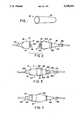
- FIG. 1is a perspective view of the barrier as would be seen if removed from the connector; for example., before it is used or applied.
- FIG. 2is a perspective view of the barrier for the connector illustrating an elastic open ended sheath for a junction between an interengaging member and a conjugating part that are the components of the connector.
- FIG. 3is a side view partially in section of the connector of FIG. 2 but the interengaging member and the conjugating part are shown engaged and the area with a reduced cross section is shown where the sleeve is cut away for illustrative purposes.
- FIG. 4is a side view as in FIG. 3 but the elastic open ended sheath for covering the juncture, is shown rolled out thereover to protect and seal the junction.
- the barrier 10 in FIG. 1is for a junction 11 in FIG. 3 between an interengaging member 12 and a conjugating part 13.
- the interengaging member 12has a body 14 which terminates in a distal end 15.
- the distal end 15most preferably has pieces 16 thereon in FIG. 2 for engaging and an edge 7 thereabout.
- the conjugating part 13 in the preferred embodimenthas a handle 18 reaching to a terminal face 19 with a periphery 20 in FIG. 2thereabout and features 21 associated therewith for matingly engaging with the pieces 16 on the distal end 15.
- the body 14 or the handle 18may have a proximal portion 22 of reduced cross section which terminates in a centrally positioned shoulder 23 facing proximally. While only one of the mentioned alternatives is shown i.e.
- a resilient sleeve 24which has an internal passage 25 shaped to snugly fit the proximal portion 22 of reduced cross section and an abutting end 26 to abut the proximally facing shoulder 23 for capture thereagainst as shown in FIG. 2.
- the interengaging member 12 and the conjugating part 13form a connector 27 when the distal end 15 pieces 16 engage the features 21 mating to form the junction 11 therebetween as seen in FIG. 3.
- the connector 27preferably has a key 28 and a keyway 29 therebetween to prealign and/or prevent rotation between the distal end 15, pieces 16 and the terminal face 19 features 21.
- the distal end 15 pieces 16 and the terminal face 19 features 21preferably include conductors with, for example, electrical circuits and optical paths.
- the junction 11is in the preferred embodiment formed about and between the interengaging member 12 and the conjugating part 13 when the pieces 16 and the features 21 are joined.
- the junctionis fully united when the distal end 15 of the body 14 is against the terminal face 19.
- a releasable locking means 30located on the body 14 for and accessible to movement when covered over by the barrier 10.
- the barrier 10is an elastic open ended sheath 31 shown in FIG. 1 and is designed for extending over the body 14 to the handle 18 or over the handle 18 to the body 14 thereby covering the junction 11.
- the sheathis shown extending from the handle 18 to the body 14.
- the covered junction 11may be locked or released by the releasable locking means 30 while within the elastic open ended sheath 31.
- the elastic open ended sheath 31is preferably gatherable to uncover the junction 11 and to reveal either the handle 18 or the body 14.
- the elastic open ended sheath 31most preferably forms a rolling seal 32 with its end opposite the captured end everted and rolled back along the extended sheath 31 to form a compact toroidal shaped accumulation 33
- sheath 31may in the preferred embodiment be formed of a latex material stretched slightly to fit about the handle 18 and body 14 when extended as shown in FIG. 4.
- the method of assembling the barrier 10 to the body 14 of the interengaging member 12 or handle 18 of the conjugating part 13 for placement over the junction 11 therebetweenmay have the steps of placing the elastic open ended sheath 31 over the reduced section of the proximal portion 22 on either the body 14 or the handle 18, placing the abutting end 26 of the sleeve 24 to capture the elastic open ended sheath 31 against the shoulder 23 of either the body 14 or the handle 18, and gathering the remainder of the elastic open ended sheath 31 toward the body 14 or the handle 18 to which it is attached for placing the sheath 31 in position for placement over the juncture 11 and toward the other.
- the step of gatheringpreferably includes the further steps of revealing either the handle 18 or the body 14 by rolling the elastic open ended sheath 31, forming the rolling seal 32 with the end opposite the captured end by everting and rolling back along the extended sheath 31 to form the compact toroidal shaped accumulation 33.
- the methodpreferably may also have the added steps of attaching of placing the resilient sleeve 24 with an internal passage 25 shaped to snugly fit the proximal portion 22 of the handle 18 or body 14 having the reduced cross section, abutting the proximally facing shoulder 23, and capturing the elastic open ended sheath 31 against the shoulder 23 with the abutting end 26.
- the method for using the barrier 10 for the junction 11 between the interengaging member 12 having the body 14 terminating in the distal end 15,is performed with steps including extending the elastic flexible sheath 31 from the handle 18 to the body 14 or from the body 14 to the handle 18 for covering the junction 11, and gathering the elastic flexible sheath 31 from the body 14 toward or the handle 18 from the handle 18 toward the body 14 for uncovering the junction 11 and for respectively revealing either the handle 18 or the body 14.
- the methodmay be reversed by extending the sheath 31 over the body 14 to the handle 18 or over the handle 18 to the body 14.
Landscapes
- Physics & Mathematics (AREA)
- General Physics & Mathematics (AREA)
- Optics & Photonics (AREA)
- Connector Housings Or Holding Contact Members (AREA)
- Electrotherapy Devices (AREA)
- Infusion, Injection, And Reservoir Apparatuses (AREA)
- Piezo-Electric Or Mechanical Vibrators, Or Delay Or Filter Circuits (AREA)
- Light Receiving Elements (AREA)
- Cable Accessories (AREA)
- Coupling Device And Connection With Printed Circuit (AREA)
Abstract
Description
Claims (1)
Priority Applications (11)
| Application Number | Priority Date | Filing Date | Title |
|---|---|---|---|
| US07/887,986US5230031A (en) | 1992-05-22 | 1992-05-22 | Barrier for a connector |
| DK93303573.5TDK0572132T3 (en) | 1992-05-22 | 1993-05-07 | Barrier to a connecting element |
| DE69304254TDE69304254T2 (en) | 1992-05-22 | 1993-05-07 | Seal for a connector |
| AT93303573TATE142052T1 (en) | 1992-05-22 | 1993-05-07 | GASKET FOR A PLUG |
| ES93303573TES2090870T3 (en) | 1992-05-22 | 1993-05-07 | SEALING DEVICE FOR CONNECTOR. |
| EP93303573AEP0572132B1 (en) | 1992-05-22 | 1993-05-07 | Barrier for a connector |
| DE9307573UDE9307573U1 (en) | 1992-05-22 | 1993-05-18 | PROTECTIVE DEVICE FOR A CONNECTOR |
| CA002096695ACA2096695C (en) | 1992-05-22 | 1993-05-20 | Barrier for a connector |
| AU38731/93AAU656468B2 (en) | 1992-05-22 | 1993-05-21 | Barrier for a connector |
| JP5120132AJPH0636822A (en) | 1992-05-22 | 1993-05-21 | Barrier for connector and mounting method of barrier |
| GR960402451TGR3021091T3 (en) | 1992-05-22 | 1996-09-19 | Barrier for a connector |
Applications Claiming Priority (1)
| Application Number | Priority Date | Filing Date | Title |
|---|---|---|---|
| US07/887,986US5230031A (en) | 1992-05-22 | 1992-05-22 | Barrier for a connector |
Publications (1)
| Publication Number | Publication Date |
|---|---|
| US5230031Atrue US5230031A (en) | 1993-07-20 |
Family
ID=25392280
Family Applications (1)
| Application Number | Title | Priority Date | Filing Date |
|---|---|---|---|
| US07/887,986Expired - Fee RelatedUS5230031A (en) | 1992-05-22 | 1992-05-22 | Barrier for a connector |
Country Status (10)
| Country | Link |
|---|---|
| US (1) | US5230031A (en) |
| EP (1) | EP0572132B1 (en) |
| JP (1) | JPH0636822A (en) |
| AT (1) | ATE142052T1 (en) |
| AU (1) | AU656468B2 (en) |
| CA (1) | CA2096695C (en) |
| DE (2) | DE69304254T2 (en) |
| DK (1) | DK0572132T3 (en) |
| ES (1) | ES2090870T3 (en) |
| GR (1) | GR3021091T3 (en) |
Cited By (9)
| Publication number | Priority date | Publication date | Assignee | Title |
|---|---|---|---|---|
| US20090018426A1 (en)* | 2007-05-10 | 2009-01-15 | Glumetrics, Inc. | Device and methods for calibrating analyte sensors |
| US20100274110A1 (en)* | 2007-02-06 | 2010-10-28 | GluMetrics, Inc | Optical determination of ph and glucose |
| US8088097B2 (en) | 2007-11-21 | 2012-01-03 | Glumetrics, Inc. | Use of an equilibrium intravascular sensor to achieve tight glycemic control |
| US8467843B2 (en) | 2009-11-04 | 2013-06-18 | Glumetrics, Inc. | Optical sensor configuration for ratiometric correction of blood glucose measurement |
| US8512245B2 (en) | 2008-04-17 | 2013-08-20 | Glumetrics, Inc. | Sensor for percutaneous intravascular deployment without an indwelling cannula |
| US8715589B2 (en) | 2009-09-30 | 2014-05-06 | Medtronic Minimed, Inc. | Sensors with thromboresistant coating |
| US8738107B2 (en) | 2007-05-10 | 2014-05-27 | Medtronic Minimed, Inc. | Equilibrium non-consuming fluorescence sensor for real time intravascular glucose measurement |
| US8838195B2 (en) | 2007-02-06 | 2014-09-16 | Medtronic Minimed, Inc. | Optical systems and methods for ratiometric measurement of blood glucose concentration |
| CN106125208A (en)* | 2016-08-29 | 2016-11-16 | 中天海洋系统有限公司 | A kind of high density watertight optical connector |
Families Citing this family (2)
| Publication number | Priority date | Publication date | Assignee | Title |
|---|---|---|---|---|
| WO2006085043A1 (en)* | 2005-02-09 | 2006-08-17 | Sandal Plc | Electrical plug adaptor |
| DE102022131364A1 (en)* | 2022-11-28 | 2024-05-29 | HARTING Electronics GmbH | Protective device for sealing a plug connection |
Citations (3)
| Publication number | Priority date | Publication date | Assignee | Title |
|---|---|---|---|---|
| JPS58162921A (en)* | 1982-03-23 | 1983-09-27 | Nec Corp | Optical connector |
| US5007704A (en)* | 1983-10-28 | 1991-04-16 | Baxter International Inc. | Oximeter |
| US5109452A (en)* | 1990-07-16 | 1992-04-28 | Puritan-Bennett Corporation | Electrical-optical hybrid connector |
Family Cites Families (5)
| Publication number | Priority date | Publication date | Assignee | Title |
|---|---|---|---|---|
| US3571782A (en)* | 1969-02-25 | 1971-03-23 | Pulse Communications Inc | Moisture and dust proof cover for an electrical connector and tool for applying same |
| JPS5256804Y2 (en)* | 1972-07-07 | 1977-12-22 | ||
| JPS5498987A (en)* | 1978-01-20 | 1979-08-04 | Nissan Motor | Waterproof connector |
| US4869683A (en)* | 1989-01-26 | 1989-09-26 | Nelson Llewellyn W | Protective enclosure for electrical plug connections |
| US5000177A (en)* | 1990-01-29 | 1991-03-19 | Cardiac Pacemakers, Inc. | Bipolar lead adapter with resilient housing and rigid retainers for plug seals |
- 1992
- 1992-05-22USUS07/887,986patent/US5230031A/ennot_activeExpired - Fee Related
- 1993
- 1993-05-07DKDK93303573.5Tpatent/DK0572132T3/enactive
- 1993-05-07EPEP93303573Apatent/EP0572132B1/ennot_activeExpired - Lifetime
- 1993-05-07ATAT93303573Tpatent/ATE142052T1/ennot_activeIP Right Cessation
- 1993-05-07DEDE69304254Tpatent/DE69304254T2/ennot_activeExpired - Fee Related
- 1993-05-07ESES93303573Tpatent/ES2090870T3/ennot_activeExpired - Lifetime
- 1993-05-18DEDE9307573Upatent/DE9307573U1/ennot_activeExpired - Lifetime
- 1993-05-20CACA002096695Apatent/CA2096695C/ennot_activeExpired - Fee Related
- 1993-05-21AUAU38731/93Apatent/AU656468B2/ennot_activeCeased
- 1993-05-21JPJP5120132Apatent/JPH0636822A/enactivePending
- 1996
- 1996-09-19GRGR960402451Tpatent/GR3021091T3/enunknown
Patent Citations (3)
| Publication number | Priority date | Publication date | Assignee | Title |
|---|---|---|---|---|
| JPS58162921A (en)* | 1982-03-23 | 1983-09-27 | Nec Corp | Optical connector |
| US5007704A (en)* | 1983-10-28 | 1991-04-16 | Baxter International Inc. | Oximeter |
| US5109452A (en)* | 1990-07-16 | 1992-04-28 | Puritan-Bennett Corporation | Electrical-optical hybrid connector |
Cited By (15)
| Publication number | Priority date | Publication date | Assignee | Title |
|---|---|---|---|---|
| US20100274110A1 (en)* | 2007-02-06 | 2010-10-28 | GluMetrics, Inc | Optical determination of ph and glucose |
| US9839378B2 (en) | 2007-02-06 | 2017-12-12 | Medtronic Minimed, Inc. | Optical systems and methods for ratiometric measurement of blood glucose concentration |
| US8983565B2 (en) | 2007-02-06 | 2015-03-17 | Medtronic Minimed, Inc. | Optical determination of pH and glucose |
| US8498682B2 (en) | 2007-02-06 | 2013-07-30 | Glumetrics, Inc. | Optical determination of pH and glucose |
| US8838195B2 (en) | 2007-02-06 | 2014-09-16 | Medtronic Minimed, Inc. | Optical systems and methods for ratiometric measurement of blood glucose concentration |
| US8738107B2 (en) | 2007-05-10 | 2014-05-27 | Medtronic Minimed, Inc. | Equilibrium non-consuming fluorescence sensor for real time intravascular glucose measurement |
| US20090018426A1 (en)* | 2007-05-10 | 2009-01-15 | Glumetrics, Inc. | Device and methods for calibrating analyte sensors |
| US8535262B2 (en) | 2007-11-21 | 2013-09-17 | Glumetrics, Inc. | Use of an equilibrium intravascular sensor to achieve tight glycemic control |
| US8979790B2 (en) | 2007-11-21 | 2015-03-17 | Medtronic Minimed, Inc. | Use of an equilibrium sensor to monitor glucose concentration |
| US8088097B2 (en) | 2007-11-21 | 2012-01-03 | Glumetrics, Inc. | Use of an equilibrium intravascular sensor to achieve tight glycemic control |
| US8512245B2 (en) | 2008-04-17 | 2013-08-20 | Glumetrics, Inc. | Sensor for percutaneous intravascular deployment without an indwelling cannula |
| US8715589B2 (en) | 2009-09-30 | 2014-05-06 | Medtronic Minimed, Inc. | Sensors with thromboresistant coating |
| US8700115B2 (en) | 2009-11-04 | 2014-04-15 | Glumetrics, Inc. | Optical sensor configuration for ratiometric correction of glucose measurement |
| US8467843B2 (en) | 2009-11-04 | 2013-06-18 | Glumetrics, Inc. | Optical sensor configuration for ratiometric correction of blood glucose measurement |
| CN106125208A (en)* | 2016-08-29 | 2016-11-16 | 中天海洋系统有限公司 | A kind of high density watertight optical connector |
Also Published As
| Publication number | Publication date |
|---|---|
| EP0572132A3 (en) | 1993-12-15 |
| DE69304254T2 (en) | 1997-01-16 |
| EP0572132B1 (en) | 1996-08-28 |
| DE69304254D1 (en) | 1996-10-02 |
| AU656468B2 (en) | 1995-02-02 |
| DK0572132T3 (en) | 1996-09-16 |
| EP0572132A2 (en) | 1993-12-01 |
| AU3873193A (en) | 1994-01-13 |
| GR3021091T3 (en) | 1996-12-31 |
| ATE142052T1 (en) | 1996-09-15 |
| CA2096695A1 (en) | 1993-11-23 |
| ES2090870T3 (en) | 1996-10-16 |
| DE9307573U1 (en) | 1993-09-23 |
| JPH0636822A (en) | 1994-02-10 |
| CA2096695C (en) | 1996-12-24 |
Similar Documents
| Publication | Publication Date | Title |
|---|---|---|
| US5230031A (en) | Barrier for a connector | |
| CA2204746C (en) | Bayonet connector for surgical handpiece | |
| US7497484B2 (en) | Medical coupling system | |
| US5390898A (en) | Needleless dual direction check valve | |
| US7763013B2 (en) | Swabable fluid connectors and fluid connector pairs | |
| US5109452A (en) | Electrical-optical hybrid connector | |
| US4068870A (en) | Flexible hose coupling | |
| WO2002096503A3 (en) | Staging medical treatment using ultrasound | |
| EP1205173A3 (en) | Safety device for a syringe assembly | |
| ES2076535T3 (en) | UNIVERSAL CONNECTOR. | |
| EP0845274A3 (en) | Angiographic syringe and luer connector | |
| WO2003066125A3 (en) | Single access dialysis needle | |
| EP0888794A3 (en) | Syringe filling and delivery device | |
| US5632643A (en) | Electronic cable yoke socket with locking mechanism | |
| JP2004536671A5 (en) | ||
| WO2022218934A1 (en) | Endoscope, in particular a medical single-use endoscope | |
| CN111405878A (en) | Robotic surgical system, instrument drive assembly and drive assembly | |
| WO2020102275A1 (en) | Method of securing the shaft of a surgical instrument to the instrument housing | |
| EP1758210B1 (en) | Return pad cable connector | |
| JP3120894B2 (en) | Endoscope connector device | |
| JP2837081B2 (en) | Gas conduit connections in gas appliances | |
| EP4580540A1 (en) | Connection systems and methods thereof | |
| JPH087954A (en) | Connector | |
| JPH04108508U (en) | Induction cord chip and its protector | |
| DE8528724U1 (en) | Electrical plug connection consisting of several plugs and a plug receptacle |
Legal Events
| Date | Code | Title | Description |
|---|---|---|---|
| AS | Assignment | Owner name:BIOMEDICAL SENSORS, LTD. A CORP. OF ENGLAND, ENG Free format text:ASSIGNMENT OF ASSIGNORS INTEREST.;ASSIGNOR:MARKLE, DAVID R.;REEL/FRAME:006126/0205 Effective date:19920325 | |
| FEPP | Fee payment procedure | Free format text:PAYOR NUMBER ASSIGNED (ORIGINAL EVENT CODE: ASPN); ENTITY STATUS OF PATENT OWNER: LARGE ENTITY | |
| FPAY | Fee payment | Year of fee payment:4 | |
| AS | Assignment | Owner name:DIAMETRICS MEDICAL LIMITED, MINNESOTA Free format text:CHANGE OF NAME;ASSIGNOR:BIOMEDICAL SENSORS LIMITED;REEL/FRAME:008579/0790 Effective date:19970407 | |
| REMI | Maintenance fee reminder mailed | ||
| LAPS | Lapse for failure to pay maintenance fees | ||
| FP | Lapsed due to failure to pay maintenance fee | Effective date:20010720 | |
| AS | Assignment | Owner name:TGC RESEARCH LIMITED, UNITED KINGDOM Free format text:ASSIGNMENT OF ASSIGNORS INTEREST;ASSIGNOR:DIAMETRICS MEDICAL LIMITED - IN LIQUIDATION;REEL/FRAME:018015/0670 Effective date:20060721 Owner name:TGC RESEARCH LIMITED, UNITED KINGDOM Free format text:ASSIGNMENT OF ASSIGNORS INTEREST;ASSIGNOR:BIOMEDICAL SENSORS LIMITED (NOW KNOWN AS DIAMETRICS MEDICAL LIMITED - IN LIQUIDATION);REEL/FRAME:018015/0694 Effective date:20060721 Owner name:TGC RESEARCH LIMITED, UNITED KINGDOM Free format text:QUITCLAIM;ASSIGNOR:DIAMETRICS MEDICAL INC.;REEL/FRAME:018015/0666 Effective date:20060724 | |
| AS | Assignment | Owner name:MEDTRONIC MINIMED, INC., CALIFORNIA Free format text:ASSIGNMENT OF ASSIGNORS INTEREST;ASSIGNOR:GLUMETRICS, INC.;REEL/FRAME:033276/0489 Effective date:20140320 | |
| STCH | Information on status: patent discontinuation | Free format text:PATENT EXPIRED DUE TO NONPAYMENT OF MAINTENANCE FEES UNDER 37 CFR 1.362 |