US5229975A - Vehicle proximity sensor - Google Patents
Vehicle proximity sensorDownload PDFInfo
- Publication number
- US5229975A US5229975AUS07/893,325US89332592AUS5229975AUS 5229975 AUS5229975 AUS 5229975AUS 89332592 AUS89332592 AUS 89332592AUS 5229975 AUS5229975 AUS 5229975A
- Authority
- US
- United States
- Prior art keywords
- bus
- sensor
- coupled
- microprocessor
- transducer
- Prior art date
- Legal status (The legal status is an assumption and is not a legal conclusion. Google has not performed a legal analysis and makes no representation as to the accuracy of the status listed.)
- Expired - Lifetime
Links
- 238000012545processingMethods0.000claimsabstractdescription34
- 230000004044responseEffects0.000claimsdescription7
- 230000000007visual effectEffects0.000claimsdescription7
- 238000000034methodMethods0.000claimsdescription5
- 230000005236sound signalEffects0.000claimsdescription5
- 238000012544monitoring processMethods0.000claims1
- 238000001514detection methodMethods0.000description21
- 238000010586diagramMethods0.000description13
- 238000013459approachMethods0.000description3
- 230000003750conditioning effectEffects0.000description2
- 238000002405diagnostic procedureMethods0.000description2
- 230000009977dual effectEffects0.000description2
- 230000000694effectsEffects0.000description2
- 238000010438heat treatmentMethods0.000description2
- 238000007689inspectionMethods0.000description2
- 230000013011matingEffects0.000description2
- 238000012360testing methodMethods0.000description2
- 101100172132Mus musculus Eif3a geneProteins0.000description1
- 230000009118appropriate responseEffects0.000description1
- 230000000712assemblyEffects0.000description1
- 238000000429assemblyMethods0.000description1
- 239000003086colorantSubstances0.000description1
- 230000003247decreasing effectEffects0.000description1
- 229910003460diamondInorganic materials0.000description1
- 239000010432diamondSubstances0.000description1
- 230000007613environmental effectEffects0.000description1
- 238000011156evaluationMethods0.000description1
- 230000008014freezingEffects0.000description1
- 238000007710freezingMethods0.000description1
- 230000001105regulatory effectEffects0.000description1
- 230000035945sensitivityEffects0.000description1
- 230000001360synchronised effectEffects0.000description1
Images


Classifications
- G—PHYSICS
- G01—MEASURING; TESTING
- G01S—RADIO DIRECTION-FINDING; RADIO NAVIGATION; DETERMINING DISTANCE OR VELOCITY BY USE OF RADIO WAVES; LOCATING OR PRESENCE-DETECTING BY USE OF THE REFLECTION OR RERADIATION OF RADIO WAVES; ANALOGOUS ARRANGEMENTS USING OTHER WAVES
- G01S15/00—Systems using the reflection or reradiation of acoustic waves, e.g. sonar systems
- G01S15/88—Sonar systems specially adapted for specific applications
- G01S15/93—Sonar systems specially adapted for specific applications for anti-collision purposes
- G01S15/931—Sonar systems specially adapted for specific applications for anti-collision purposes of land vehicles
- G—PHYSICS
- G01—MEASURING; TESTING
- G01S—RADIO DIRECTION-FINDING; RADIO NAVIGATION; DETERMINING DISTANCE OR VELOCITY BY USE OF RADIO WAVES; LOCATING OR PRESENCE-DETECTING BY USE OF THE REFLECTION OR RERADIATION OF RADIO WAVES; ANALOGOUS ARRANGEMENTS USING OTHER WAVES
- G01S7/00—Details of systems according to groups G01S13/00, G01S15/00, G01S17/00
- G01S7/52—Details of systems according to groups G01S13/00, G01S15/00, G01S17/00 of systems according to group G01S15/00
- G01S7/64—Luminous indications
- G—PHYSICS
- G01—MEASURING; TESTING
- G01S—RADIO DIRECTION-FINDING; RADIO NAVIGATION; DETERMINING DISTANCE OR VELOCITY BY USE OF RADIO WAVES; LOCATING OR PRESENCE-DETECTING BY USE OF THE REFLECTION OR RERADIATION OF RADIO WAVES; ANALOGOUS ARRANGEMENTS USING OTHER WAVES
- G01S7/00—Details of systems according to groups G01S13/00, G01S15/00, G01S17/00
- G01S7/003—Transmission of data between radar, sonar or lidar systems and remote stations
- Y—GENERAL TAGGING OF NEW TECHNOLOGICAL DEVELOPMENTS; GENERAL TAGGING OF CROSS-SECTIONAL TECHNOLOGIES SPANNING OVER SEVERAL SECTIONS OF THE IPC; TECHNICAL SUBJECTS COVERED BY FORMER USPC CROSS-REFERENCE ART COLLECTIONS [XRACs] AND DIGESTS
- Y10—TECHNICAL SUBJECTS COVERED BY FORMER USPC
- Y10S—TECHNICAL SUBJECTS COVERED BY FORMER USPC CROSS-REFERENCE ART COLLECTIONS [XRACs] AND DIGESTS
- Y10S367/00—Communications, electrical: acoustic wave systems and devices
- Y10S367/907—Coordinate determination
Definitions
- This inventionrelates to alternate vision systems and more particularly to vehicle mounted proximity sensing systems.
- alternate vision systemsare near proximity detection systems designed to be used in conjunction with the mirroring system of a motor vehicle.
- Such systemsalert the driver of the vehicle on which the system is mounted to the existence of an object in a vehicle's blind spot, e.g., that area to the side and rear of the vehicle which is not visible through the use of mirrors or other means.
- blind spotsgenerally exist, for example, near the rear ends of a car, next to the rear wheels of a truck or next to the right side of a truck and in particular next to the right side of the cab of the truck.
- a school busmay have a need to detect the presence of small children near a front region of the bus when the children enter and exit the bus.
- One solution to this problemis to provide a proximity sensor on every side of a vehicle.
- sensorsare typically provided as infrared, radar, or ultrasonic detectors.
- the sensorsare typically coupled to a central computer system which is in turn coupled to a control and display console which is typically disposed where the driver of the vehicle may view the display.
- the display consoletypically does not provide an indication of which sensor is in close proximity to an object.
- the operator of a vehiclemay know that he is in close proximity to some object, he may not be aware of the particular location of the object.
- a second problem with this approachis that it is often difficult to determine if the sensors disposed on the vehicles are operating correctly. To determine if the sensors are operating correctly requires a first person bringing an object in proximity to a sensor and a second person viewing the display console inside the vehicle to determine if the sensor is sending a proximity signal to the console.
- a third problem with this approachis that such systems generally fail to detect and report the failure of a particular sensor.
- a vehicle sensing systemincludes a data bus, a first microprocessor coupled to the bus and a plurality of sensor modules coupled to the bus, with each of such sensor modules capable of detecting the presence of objects within a first predetermined distance of the sensor module.
- Each sensor moduleincludes a transducer, a second microprocessor coupled between the transducer and the bus, for processing information received from the transducer, a light emitting diode coupled to the second microprocessor for providing a visual indication of when an object is within the first predetermined distance of the sensor module or when the sensor module is faulty.
- the vehicle sensing systemfurther includes a temperature sensing circuit coupled to the second microprocessor and a bus transceiver coupled between the second microprocessor and the bus for receiving information from the bus and for transmitting information to the bus.
- a vehicle sensing systemfor use on a motor vehicle, such as a truck for example, is provided.
- the plurality of sensor modulesmay be disposed about a vehicle body and a driver alert module display may be coupled to the first microprocessor and disposed on the vehicle such that an operator of the vehicle may view the driver alert module display.
- the light emitting diode (LED)may be disposed on a first surface of a housing in which the transducer is also disposed.
- the second microprocessorWhen an object is within the detection range of the sensor module the second microprocessor provides a signal to the LED which causes the LED to illuminate indicating that an object has been detected.
- an objectWhen inspecting the sensor module an object may be placed within the detection range of the sensor module. If the sensor module is operating correctly the LED provides a visual indication that the sensor module has detected an object.
- the LEDprovides a visual indication which may be viewed external to the sensor module during inspection and diagnostics of each sensor module of whether the sensor module is operating correctly.
- the inspection and diagnostics of the vehicle sensing systemmay be performed by a single person.
- each sensor modulemay be programmed to recognize its location on the vehicle and along the bus.
- each of the sensor modulesmay be programmed to respond to objects at varying distances from the sensor module.
- a varying number of sensor modulesmay be parallel coupled along the bus to provide a vehicle sensing system capable of being disposed on a variety of different motor vehicles, each having a different length. That is the number of sensors may be increased or decreased, as required, depending on the size of the vehicle and the areas around the vehicle within which it is desired to detect objects.
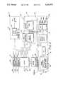
- FIG. 1is a block diagram view of a vehicle sensing system
- FIG. 1Ais a block diagram of a bus which may be used in the vehicle sensing system of FIG. 1;
- FIG. 2is a block diagram view of a driver alert module
- FIG. 2Ais a block diagram view of an enhanced display module which may be used in the driver alert module of FIG. 2;
- FIG. 3is a block diagram of a sensor which may be used in the vehicle sensing system of FIG. 1;
- FIG. 4is an exemplary flow diagram of processing steps which may be performed by the microprocessor in the driver alert module of FIG. 2;
- FIG. 5is an exemplary flow diagram of the processing steps which may be performed by the microprocessor in the sensor of FIG. 3;
- FIG. 6is a block diagram of a sensor system disposed on a loading dock.
- a vehicle sensing system 10includes a driver alert module 11 coupled to a bus, here an asynchronous three-wire data bus 14 which may be of the type, for example, used in a local area network and having the carrier sense multiple access/collision detect (hereinafter CSMA/CD) protocol. Those of skill in the art however will recognize that other network protocols may also be used.
- the driver alert module 11provides an interface between an electrical system of a vehicle (not shown) on which the vehicle sensing system 10 is disposed and the vehicle sensing system 10.
- the driver alert module 11includes a plurality of input and output terminals 12a-12e generally denoted 12.
- Terminals 12a and 12bare coupled to first and second reference potentials which may be a positive and a ground terminal of a 12 volt battery, for example.
- Terminals 12c through 12emay be coupled to left-turn, right-turn and rear-motion signal indicators respectively of the vehicle (not shown) on which the system 10 is disposed.
- a single driver alert module 11is coupled to the bus 14.
- the bus 14has coupled thereto a plurality of, here female, connectors 16a-16n to which mating, here male, connectors 18a-18n may be connected. Those of skill in the art will recognize that other connector types may also be used. It should also be noted that the bus 14 maybe provided as a plurality of bus sections as will be described in conjunction with FIG. 1A.
- a bus 14'may be provided as a plurality of bus sections 15a-15n.
- bus section 15aincludes a first bus connector 17a coupled to a first end of the bus section 15a, a second bus connector 17b coupled to a second end of the bus section 15a, and a third bus connector 16a' coupled to the bus section 15a in a region between the first and second bus connectors.
- a plurality of such bus sectionsmay be coupled with first ones of the bus connectors 17a being coupled to second ones of the second bus connectors 17b to provide the bus 14'.
- the plurality of sensors 22a-22n(FIG.
- bus sections 15a and 15bmay be parallel coupled (i.e., daisy- chained) to the bus connectors 16a'-16n'.
- the last bus section 15nincludes only the first bus connector 17a and the third bus connector 16n' which may be coupled to a sensor module 22n (FIG. 1) for example.
- the last bus section 15nmay be provided as a 3 connector bus section similar to bus section 15a for example.
- bus sections 15a and 15bmay be coupled together via an intermediate bus section (not shown) which simply spaces the bus sections 15a and 15b a predetermined distance apart.
- the connectors 16a and 18ahere couple a driver alert module 20 to the bus 14.
- Power signals and data signalsare provided to the driver alert module 20 via power line 20a, ground line 20b and data line 20c.
- the driver alert module 20will be described further in conjunction with FIG. 2. Suffice it here to say that the driver alert module interfaces with a plurality of sensor modules 22a-22n through the bus 14.
- Each sensor module 22a-22nis coupled to the bus 14 via the bus connectors 16b-16n and the mating connector 18b-18n as shown. Also, each sensor module 22a-22n includes a sensor 24 having an external object detection indicator 26, here provided as a light emitting diode, disposed thereon. The light emitting diode 26 indicates when an object is within a first predetermined range of distances of the corresponding sensor 22a-22n.
- sensor 22amay have a plurality of predetermined range of distances in which it detects objects.
- LED 26may illuminate in a first color, yellow for example, to indicate the presence of an object in a first one of the plurality of predetermined range of distances of sensor 22a.
- the LED 26may also illuminate in a second color, red for example, to indicate the presence of an object in a second different one of the plurality of predetermined range of distances of the sensor 22a.
- LED 26may be provided as an LED assembly disposed in a single LED housing (not shown). LED assemblies which emit two or more different colors of light are commercially available and well known to those of skill in the art.
- the LED 26may indicate, by flashing for example, when the corresponding sensor 22a-22n is faulty as will be described further in conjunction with FIG. 3.
- the present bus structure 14 or 14'(FIG. 1A) is capable of supporting a combination of sensors 22a-22n and driver alert modules 11 totalling two hundred and fifty-six.
- one driver alert module and two hundred fifty-five sensorsmay be coupled to the bus 14.
- two driver alert modules and two hundred and fifty-four sensorsmay be coupled to the bus 14.
- Other combinations of driver alert and sensor modulesmay also be used.
- Other bus structuresmay, of course, be capable of supporting more than a total two hundred and fifty-six sensors and driver alert modules.
- driver alert module 11having the input and output terminals 12a-12e described above in conjunction with FIG. 1 is shown to include a microprocessor 28.
- the driver alert module 11further includes a power conditioning circuit 30 and a plurality of protection circuits 32a-32d which protect voltage sensitive circuit elements such as the microprocessor 28, for example, from signals having voltage levels capable of damaging such voltage sensitive circuit elements.
- the microprocessor 28is coupled to a memory 34, here an electrically, erasable, programmable read only memory (EEPROM).
- the microprocessor 28is further coupled to a bus transceiver 36 which is coupled to the data line 14c of the bus 14 via the terminal 20c.
- the microprocessor 28is also coupled to a display interface 38 and provides clock, data and load signals thereto.
- the display interface 38is coupled to a display 40 which includes a photo-cell (not shown) coupled to an LED driver circuit 42.
- the LED driver circuit 42is coupled to here three LEDs generally denoted 44.
- a first LED 44aemits a green light to indicate the sensor modules 22a-22n (FIG. 1) are operating within their normal parameters. If one of the operating parameters of a sensor module is not within the normal operating parameters however then the LED 44a emits a red rather than green light. Thus the color of the light emitted by LED 44a may change in response to diagnostics performed by one or all of the sensors 22a-22n (FIG. 1).
- a second LED 44bemits a green light to indicate the driver alert module 11 (FIG. 1) is operating within its normal parameters and is properly coupled to the bus 14 (FIG. 1). If one of the operating parameters of the driver alert module 11 is not within the normal operating parameters however then the LED 44b emits a red rather than green light to indicate the existence of a problem in the driver alert module 11.
- a third LED 44cemits a light when any one of the plurality of proximity sensors 22a-22n detect an object within a first predetermined distance.
- the photo-cellis here used to adjust the brightness of the LEDs to in response to the surrounding light.
- an enhanced display module 40'is shown to include here a shift register 46 and an LED segment and digit driver 48 coupled to a dual seven segment display 50 to indicate a distance to a detected object.
- a shift register 46and an LED segment and digit driver 48 coupled to a dual seven segment display 50 to indicate a distance to a detected object.
- any means well known to those of skill in the arte.g. a direct connection, etc . . . ) may be used to provide data from the microprocessor 28 (FIG. 2) to the LED segment digit driver 48.
- a plurality of LEDs 44a'-44g' generally denoted 44'are disposed about a diagrammatical view of the vehicle 45, here a truck for example, on which the sensor modules 22a-22n (FIG. 1) are disposed.
- the number of LEDs 44'need not have a one to one correspondence with the number of sensors 22 (FIG. 1) disposed on the vehicle. Thus either more or fewer sensors than LEDs may be disposed to provide the vehicle sensing system 10 (FIG. 1).
- microprocessor 28performs the processing required to determine which particular LED 44' will be illuminated.
- the corresponding LED 44a'-44g'In operation when an object enters the detection zone of each of the sensors 22a-22n the corresponding LED 44a'-44g' emits a light.
- the LED 44' representative of the sensor 22a-22n (FIG. 1) to which the object is closestwill blink and the distance between the object and that particular sensor will be displayed on the dual seven segment display 50.
- the range displayed on the seven segment display 50will correspond to the zone of the particular LED 44a'-44g' to which the object (not shown) is closest.
- First and second LED's 44h', 44i'illuminate to indicate when the vehicle sensing system 10 (FIG. 1) is on or off.
- a third LED 44j'is automatically illuminated to indicate to an operator of the vehicle the failure of one of the sensors 22a-22n (FIG. 1).
- the driver alert module 11further includes an audio circuit 51 coupled to the microprocessor 28.
- the audio circuit 51includes an audio driver circuit 52 coupled between the microprocessor 28 and a speaker 54.
- the audio circuit 51provides an audio tone to indicate a failure in one of the sensor modules 22a-22n (FIG. 1) or a failure in the driver alert module 11 (FIG. 1).
- a volume control circuit 56here provided as a variable resistor provides volume control to the speaker 54.
- the microprocessor 28may be programmed such that, in response to an object entering a predetermined distance of one of the sensors 22a-22n (FIG. 1), the microprocessor 28 provides a signal to the audio driver circuit 52 and generates an audio signal via the speaker 54.
- the vehicle sensing system 10actively alerts the user of the system 10 of the existence of a proximate object.
- Passive systemsrequire the operator to continuously monitor and interrogate such systems for information on proximate objects.
- the sensor module 22a(FIG. 1) includes a microprocessor 60 coupled to a memory 62, here an electrically erasable programmable read only memory (EEPROM).
- the microprocessor 60is also coupled to a pair of detector LEDs 64a, 64b, here, a first one 64a of said pair being red and a second one 64b of said pair being yellow.
- the LED's 64a, 64bprovide the external object detection indicator 26 (FIG. 1).
- the red LED 64awhich is visible external to the sensor 24, is coupled to the microprocessor and indicates when an object is detected in a first selected active range of detection.
- the yellow LED 64bemits a yellow light when an object is detected in a second selected active range of detection. This permits the operator of a vehicle on which the vehicle sensing system 10 (FIG. 1) is disposed to isolate faulty sensors.
- constant flashing of the red LED 64amay indicate the existence of a single faulty sensor module in a plurality of sensor modules 22a-22n (FIG. 1).
- the LEDs 64a, 64b and transducerare disposed on a first external surface of a housing inside which the microprocessor 60 and other electronics, to be descrbed below, which provide the sensor module 22a are disposed.
- the sensor module 22aincludes a power conditioning circuit 61 coupled to the power line 14a of the bus 14 (FIG. 1) via the line 24a.
- a voltage regulator circuit 61aprovides regulated voltage to other circuit elements of the sensor module 22a.
- the sensor module 22aalso includes a bus transceiver 65 coupled between a data terminal 24c and the microprocessor 60.
- the bus transceiver 65transmits and receives signals between the microprocessor 60 and the data line 14c of the bus 14 (FIG. 1).
- a protection circuit 63is disposed between the terminal 24c and the bus transceiver 65 to protect the bus transceiver 65 and microprocessor 60 from signals on the data line 14c (FIG. 1) having voltage levels which may damage either the microprocessor 60 or the bus transceiver 65.
- a transducer 66here provided as an ultrasonic transducer but alternatively provided as an infrared transducer, for example, is coupled to a transducer driver 68.
- the transducer driver 68is coupled to the microprocessor 60 and a voltage step-up circuit 70.
- the voltage step-up circuit 70provides the requisite voltage needed to drive the particular type of transducer 66 coupled thereto.
- a heating element 72is disposed near the ultrasonic transducer 66 to maintain a predetermined range of temperatures on the transducer 66.
- a temperature sensing circuit 74is here coupled to an analog to digital converter 76 (hereinafter ADC) which is coupled to the microprocessor 60.
- ADCanalog to digital converter
- the temperature sensing circuit 74monitors ambient temperature about the sensor 24 and provides such information to the ADC 76 and consequently to the microprocessor 60.
- the microprocessor 60controls the heating temperature of the heater 72 and thus provides the transducer 66 having a surface temperature above freezing to prevent ice and snow, for example, from accumulating on the transducer 66.
- the transducer 66is also coupled to an envelope detector 78 and a gain circuit 80.
- the gain circuit 80provides amplified signals to the microprocessor 60.
- the envelope detector 78provides signals to the ADC 76 which receives the analog signals fed thereto and provides a digital representation of such signals to the microprocessor 60.
- the microprocessor 60may adjust the frequency, amplitude and gain characteristics of the transmitted signal to improve the received signal characteristic and provide optimum sensor module performance (e.g., reduce number of false alarms, etc. . . . )
- the microprocessor 60 disposed in each sensor module 22a-22nimproves the real time processing of the transmit and receive signal pulses and thereby improves the performance of the sensor module 22a.
- the microprocessor 60is also programmed to provide a plurality of detection levels.
- the microprocessor 60may provide continuous acquisition of objects and resultant range information.
- the microprocessor 60may provide a continuous evaluation of the performance of the sensor module 22a and detect and report failures which occur within the sensor module 22a.
- each sensor module 22a-22nmay be disposed in a particular location on the vehicle and have its own particular detection range or ranges. That is, each sensor module 22a-22n (FIG. 1) may have a first detection range of fifteen feet for example and a second detection range of ten feet for example.
- LED 26may emit a yellow light when an object is within 15 feet of the corresponding sensor module and the LED 26 may emit a red light when the object is within 10 feet of the sensor module.
- the microprocessor 60may operate in a stand-alone mode for applications that only require object detection (e.g., discriminating alarms, door opening, etc. . . . )
- the microprocessor 60may also be programmed to provide continuous or synchronized modes for the parallel sensor modules 22a-22n. Furthermore, the microprocessor 60 determines the object proximity required prior to alarm output and provides the upper pulse duration and signature as well as the minimum detection threshold.
- the sensor module 22ais a stand-alone object detection module.
- the three wire connection to the bus 14 (FIG. 1) via the connectors 18b-18npermits relatively easy replacement of a damaged or faulty sensor module 22a-22n.
- a damaged or inoperative sensor modulemay simply be "unplugged” from the bus 14 and in replacement thereof a properly operating sensor module may be "plugged in” to the bus 14.
- FIG. 4shows a flow diagram of the processing performed in the microprocessor 28 (FIG. 2) of the driver alert module 11 (FIG. 2) to produce an output on the display (40 FIG. 2 or 40' FIG. 2A).
- processing blocksrepresent computer software instructions or groups of instructions.
- diamond shaped elementsrepresent computer software instructions or groups of instructions which affect the execution of the computer software instructions represented by the processing blocks.
- decision blocksrepresent computer software instructions or groups of instructions which affect the execution of the computer software instructions represented by the processing blocks.
- the flow diagramdoes not depict syntax or any particular computer programming language. Rather, the flow diagram illustrates the functional information one skilled in the art requires to generate computer software to perform the processing required of driver alert module 20'. It should be noted that many routine program elements such as initialization of loops and variables and the use of temporary variables are not shown.
- the driver alert module 11is coupled to the bus 14 and monitors the signals which appear on the bus 14.
- a plurality of sensor modules 22a-22nare coupled to the bus 14.
- processing block 82performs an initialization procedure in which the driver alert module 11, for example, detects the presence of each sensor module 22a-22n on the bus 14 and creates a "list" of active sensor modules. Furthermore the microprocessor 28 will ascertain the parameters of each sensor module 22a-22n and include such parameters in its list of active sensor modules. Parameters of the sensor modules 22a-22n may include but are not limited to sonar frequency, sonar pulse duration, sonar pulse amplitude, sonar pulse transmit voltage drain, positional identification, unique identification number, distance warning range and distance alert for example.
- the driver alert module 11will detect the presence of a sensor module 22a-22n which has not previously been "logged on” and will detect the addition of new sensor modules and their parameters and include the information in the list of active sensor modules.
- a signal on the bus 14indicates a simultaneous loss of all trailer resident sensor modules and the reinstatement of sensor modules with differing unique identification addresses, the driver alert module 11 assumes a trailer detached and reconnect has occurred and resets the list of active sensor modules 22a-22n without operator intervention.
- Each driver alert module and each sensor modulehas a first unique identification code. This allows the cab containing the driver alert module and the trailer equipped with sensor modules to be uniquely identified. This information may be used, for example, to allow automated systems to make certain that predetermined trailers are connected to corresponding predetermined cabs and assigned to a corresponding predetermined driver.
- Each sensor module 22a-22nhas a second unique identification code which corresponds to the location at which the sensor is disposed.
- Decision block 84determines whether self or system diagnostics should be performed. That is, each sensor module 22a-22n may independently decide to run diagnostic tests on itself. Furthermore all or a particular one of the driver alert modules 22a-22n may receive a message on the bus from the driver alert module or other device coupled to the bus, for example, which prompts the sensor module to perform a diagnostic self test or system test.
- decision block 84If a decision is made in decision block 84 to perform the diagnostics then either the self or system diagnostic routine may be performed as shown in processing block 88. If a decision is made not to perform diagnostics then processing continues at decision block 86.
- Decision block 86implements a loop wherein the driver alert module 11 monitors the bus 14 and determines if a valid message signal is on the bus 14.
- the source of the signalmay be from one of a plurality of sources including but not limited to any one of the sensor modules 22a-22n.
- the source of the signalmay be a directional indicator of the cab (e.g., to indicate the vehicle will turn), a reverse signal from the cab (e.g. to indicate the vehicle will back up) or the like.
- the driver alert modulemay modify the signal provided to the audio driver 52 in the driver alert module 11 or retrieve data from the EEPROM 34.
- the driver alert modulemay provide a signal to the bus which commands the sensor to perform diagnostics.
- decision block 90determines if the message is a proximity message being sent from one of the plurality of sensor modules 22a-22n. If the signal is not a proximity signal, the driver alert module 11 provides an appropriate response to the signal as shown in processing block 92. For example the driver alert module may modify the signal provided to the audio driver circuit 52 or retrieve data from the EEPROM 34. Alternatively, the driver alert module may provide a signal to the bus which commands the sensor to perform diagnostics.
- the microprocessor 28provides the appropriate signal to the display which is coupled thereto.
- the microprocessor 28provides to the display 40' both the location of the sensor 22a-22n and the distance between the sensor and the detected object as shown in processing block 94.
- the driver alert module 11examines the sender (i.e., the particular sensor module) of the proximity message to determine the physical location of the sensor.
- the microprocessor 28determines the data to be displayed based upon the type of display mechanism provided in the driver alert module.
- the enhanced driver alert module display 40'(FIG. 2A) provides the ability to indicate seven zones around a vehicle.
- the color, position, and flash rate of the LEDs 44a-44g'also convey information on the severity of the warning and the status of the individual sensors 22a-22n. Processing then continues at decision block 84 as described hereinabove.
- the driver alert module 11may also operate in a programming mode wherein the microprocessor 28 may modify one or several parameters of a particular one or of all of the sensors. This mode may be activated, for example, by providing power to the driver alert module 11 and within ten seconds indicating three right turns followed by three left turns. Thereafter, the left turn signal, the right turn signal, and the reverse selection signal are used to select, for example, the sensor of interest, the parameter to modify, (e.g., threshold, position identification, etc.) and sets of parameter values.
- the programming mode of operationmay, of course, be entered into at any time during the processing steps described hereinabove in conjunction with FIG. 4. Other schemes to enter the programming mode or a diagnostic mode, for example, may also be used.
- Processing block 96includes an initialization process in which the sensor module 22a may "log on” to the bus 14 and provide to the driver alert module 11 data corresponding to presence, location and unique identification number of the sensor module 22a. Alternatively and or in addition to the sensor “logging on” the driver alert module 11 (FIG. 1) periodically requests identification information from devices, such as the sensors 22a-22n (FIG. 1) for example, coupled to the bus 14.
- the driver alert module 11may inspect or modify parameters which are stored in the memory 62 (FIG. 3) of the sensor module 22a including but not limited to sonar frequency, sonar pulse duration, sonar pulse amplitude, sonar pulse transmit voltage drain, positional identification, unique identification number, distance warning range and distance alert range.
- decision block 98the sensor module determines if it has received a valid message signal on the bus 14.
- sensor module 22aprocesses the message as shown in processing block 100. If the message signal is not valid then decision block 98 skips processing block 100 and processing continues at decision block 102.
- the sensor module 22amay perform self-diagnostics. If it is desirable to perform such diagnostics, then the sensor module 22a runs a diagnostic subroutine as shown in processing block 104. After completion of the diagnostics routine the result of the diagnostic tests may be reported both locally to the sensor module itself and the diagnostic results may also be transmitted to the bus in the form of a diagnostic message signal. Regardless of whether diagnostics are performed, the sensor module 22a proceeds into its detection mode.
- a signal pulseis transmitted from the sensor module 22a via the transducer 66 (FIG. 3).
- Processing block 110receives a return pulse and processing block 112 computes the distance of the object nearest to the proximity sensor. Distance is sensed by first developing a varying voltage electrical signal which is converted into a sound pulse of a given frequency and duration. Next the sensor measures the time it takes for the transmitted signal pulse to return as an echo signal.
- the voltage step up circuit 70(FIG. 3) allows the voltage level of the transmitted signal pulse to be varied to accommodate various types of electrical to sound transducers which may be used in the sensor module 22a.
- the detection circuit 78(FIG. 3) measures the voltage level of the transmitted pulse to determine if the proper voltage has been generated and transmitted.
- the microprocessor 60 in the sensor module 22aprovides a means for varying the frequency of the transmitted pulse to thus accommodate various types of electrical to sound transducers which may be disposed in the sensor.
- the temperature sensor datais used in the calculations which convert the measured time data to a corresponding distance.
- the microprocessor 60may vary the repetition rate of the transmitted sound pulse in a random fashion to minimize interference with other like sensor modules.
- the sensor module 22ais frequency agile, transmit power agile, and receive sensitivity agile. This technique allows ranging the above-mentioned parameters in response to surrounding environmental or other conditions, for example, to maximize the number of valid signals and minimize the number of erroneous responses (i.e., false alarms).
- Decision block 114determines if the distance computed in processing block 112 should be reported to the bus 14.
- the microprocessor 60selectively decides to report a distance based on a minimum threshold per sensor module. If the minimum threshold per sensor module is not met then processing loops to the decision block 98 where diagnostics may again be performed. If the reporting distance is met (i.e., if the distance between the detected object and the sensor module 22a is within a first predetermined range of distances), then processing continues to processing block 116 where the output distance data and the sensor identification are output to the bus 14 to be received by the driver alert module 11 as described hereinabove in conjunction with FIG. 4.
- the microprocessors 28 and 60are preferably provided having multi-tasking operating systems. Thus, many of the above-described steps may be performed simultaneously.
- the driver alert module 11may simultaneously monitor the bus activity, send and receive messages as required and perform any required computations.
- the sensor module 22amay, for example, simultaneously monitor the bus 14 and perform the required computations to compute the distance between the module 22a and a detected object.
- the vehicle sensing system 10(FIG. 1) is shown disposed on a stationary object, here a loading dock 120 having a plurality of loading bays 121a-121n.
- the vehicle sensing system 10detects objects moving in relation to the loading dock 120.
- a portion of a vehicle 122is shown moving in the direction of the loading dock.
- the sensor module 22ais disposed along the edge of the loading bay 121a and detects the movement of the vehicle 122.
- Sensor 22aprovides the information along the bus 14 to the driver alert module 11 which may be located for example in office of the truck dispatcher along with an appropriate display 40" coupled thereto.
- the display 40"may provide an indication via a corresponding LED 44a"-44n" of which loading bays 122a-122n have objects within the detection range of the corresponding sensors 22a-22n.
- an audio signalmay be provided as to indicate movement as described hereinabove in conjunction with FIG. 2.
- a truck dispatchermay monitor movement of vehicles or other objects moving in the proximity of the loading bays 121a-121n of the loading dock 120.
Landscapes
- Engineering & Computer Science (AREA)
- Radar, Positioning & Navigation (AREA)
- Remote Sensing (AREA)
- Physics & Mathematics (AREA)
- Computer Networks & Wireless Communication (AREA)
- General Physics & Mathematics (AREA)
- Acoustics & Sound (AREA)
- Length Measuring Devices With Unspecified Measuring Means (AREA)
Abstract
Description
Claims (24)
Priority Applications (1)
| Application Number | Priority Date | Filing Date | Title |
|---|---|---|---|
| US07/893,325US5229975A (en) | 1992-06-03 | 1992-06-03 | Vehicle proximity sensor |
Applications Claiming Priority (1)
| Application Number | Priority Date | Filing Date | Title |
|---|---|---|---|
| US07/893,325US5229975A (en) | 1992-06-03 | 1992-06-03 | Vehicle proximity sensor |
Publications (1)
| Publication Number | Publication Date |
|---|---|
| US5229975Atrue US5229975A (en) | 1993-07-20 |
Family
ID=25401379
Family Applications (1)
| Application Number | Title | Priority Date | Filing Date |
|---|---|---|---|
| US07/893,325Expired - LifetimeUS5229975A (en) | 1992-06-03 | 1992-06-03 | Vehicle proximity sensor |
Country Status (1)
| Country | Link |
|---|---|
| US (1) | US5229975A (en) |
Cited By (84)
| Publication number | Priority date | Publication date | Assignee | Title |
|---|---|---|---|---|
| US5786772A (en)* | 1996-03-22 | 1998-07-28 | Donnelly Corporation | Vehicle blind spot detection display system |
| DE19707651A1 (en)* | 1997-02-26 | 1998-08-27 | Itt Mfg Enterprises Inc | Ultrasonic distance measuring system with digital measuring signals transmitted in time-division multiplex |
| WO1998038528A1 (en)* | 1997-02-27 | 1998-09-03 | Drexelbrook Controls, Inc. | Condensate free ultrasonic transmitter |
| US5844471A (en)* | 1997-06-13 | 1998-12-01 | Itt Manufacturing Enterprises, Inc. | Heated vehicle exterior object sensor |
| US5895441A (en)* | 1995-04-28 | 1999-04-20 | Schneider Electric Sa | Learning proximity detector |
| EP0977304A1 (en)* | 1998-07-28 | 2000-02-02 | Koninklijke Philips Electronics N.V. | Communication apparatus, mobile radio equipment, base station and procedure to control the output power |
| US6067080A (en)* | 1997-02-21 | 2000-05-23 | Electronics For Imaging | Retrofittable apparatus for converting a substantially planar surface into an electronic data capture device |
| US6163505A (en)* | 1996-07-01 | 2000-12-19 | Itt Manufacturing Enterprises, Inc. | contact member for an ultrasonic transducer |
| US6282969B1 (en) | 1998-09-30 | 2001-09-04 | Veleo Electrical Systems, Inc. | Optically clear housing and reduced cure time potting compound for use with object sensor |
| US6292177B1 (en) | 1997-03-05 | 2001-09-18 | Tidenet, Inc. | Marking device for electronic presentation board |
| EP1150135A1 (en)* | 2000-04-28 | 2001-10-31 | Valeo Schalter und Sensoren GmbH | Parking assistance device with temperature compensation |
| WO2001085491A1 (en)* | 2000-05-08 | 2001-11-15 | Automotive Technologies International, Inc. | Vehicular blind spot identification and monitoring system |
| US6326565B1 (en) | 1997-02-28 | 2001-12-04 | Electronics For Imaging, Inc. | Marking device for electronic presentation board |
| WO2001061377A3 (en)* | 2000-02-16 | 2002-06-27 | Altra Technologies Inc | Scalable sensor systems based on sensor modules |
| WO2002006852A3 (en)* | 2000-07-18 | 2002-06-27 | Sense Technolgies Inc | Programmable microwave back-up warning system and method |
| US20030034883A1 (en)* | 2001-08-14 | 2003-02-20 | Yoshihisa Sato | Obstacle detecting apparatus and related communication apparatus |
| WO2003073126A1 (en)* | 2002-02-22 | 2003-09-04 | Robert Bosch Gmbh | Method and device for transmitting measurement data via a can bus in an object detection system for motor vehicles |
| US6690616B1 (en)* | 1998-08-06 | 2004-02-10 | Ulrich Bahr | Method and device for detecting objects, especially used as a parking assistance device in a motor vehicle |
| US6710302B1 (en)* | 2002-10-31 | 2004-03-23 | Mark Rennick | Vehicle sensor assembly including integral heating unit |
| US6714132B2 (en) | 2001-10-11 | 2004-03-30 | The United States Of America As Represented By The Administrator Of The National Aeronautics And Space Administration | Self-activating system and method for alerting when an object or a person is left unattended |
| US6717515B1 (en)* | 1999-10-29 | 2004-04-06 | Omron Corporation | Sensor system |
| US6774810B2 (en) | 1998-02-18 | 2004-08-10 | Donnelly Corporation | Rearview mirror assembly incorporating supplemental inflatable restraint system status information display |
| US6788190B2 (en) | 2001-11-28 | 2004-09-07 | Sense Technologies, Inc. | Trailer hitch mount for vehicle backup sensor |
| US20040254713A1 (en)* | 2003-06-10 | 2004-12-16 | Mitsubishi Denki Kabushiki Kaisha | Vehicle safety apparatus |
| GB2404250A (en)* | 2003-07-25 | 2005-01-26 | Shih-Hsiung Li | Vehicular obstacle detection system with ultrasonic sensors connected to firing sequence controller through data bus |
| US20050062591A1 (en)* | 2003-09-05 | 2005-03-24 | Ervin Cheryl P. | Rear turning signal sensor |
| US20050075770A1 (en)* | 2003-10-07 | 2005-04-07 | Taylor Ronald M. | Motor vehicle back-up system |
| US6894608B1 (en) | 1999-07-22 | 2005-05-17 | Altra Technologies Incorporated | System and method for warning of potential collisions |
| US6933837B2 (en) | 2002-01-25 | 2005-08-23 | Altra Technologies Incorporated | Trailer based collision warning system and method |
| US20050278098A1 (en)* | 1994-05-23 | 2005-12-15 | Automotive Technologies International, Inc. | Vehicular impact reactive system and method |
| US20060055520A1 (en)* | 2004-09-13 | 2006-03-16 | Spencer Irvine | Actuated braking and distance sensing system for operational regulation of belt loader equipment |
| US7050509B2 (en) | 1997-04-22 | 2006-05-23 | Silicon Laboratories Inc. | Digital isolation system with hybrid circuit in ADC calibration loop |
| US20060197521A1 (en)* | 2005-03-03 | 2006-09-07 | Trw Automotive U.S. Llc | Apparatus for sensing the proximity of a vehicle to an object |
| US20060273927A1 (en)* | 2005-06-01 | 2006-12-07 | Denso Corporation | Obstacle detection device for vehicle |
| US20070058257A1 (en)* | 2005-09-14 | 2007-03-15 | Lynam Niall R | Display device for exterior rearview mirror |
| US20080042865A1 (en)* | 2006-08-09 | 2008-02-21 | Dock Watch, Llc | Loading dock monitoring device and method |
| US20080202243A1 (en)* | 2005-06-13 | 2008-08-28 | Robert Ray Gross | Methods and Device for Ultrasonic Range Sensing |
| WO2009040155A1 (en)* | 2007-09-24 | 2009-04-02 | Robert Bosch Gmbh | Driver assistance system and method for the operation thereof |
| WO2009109243A1 (en) | 2008-03-07 | 2009-09-11 | Robert Bosch Gmbh | Ultrasound-based driver assistance system |
| US20090261979A1 (en)* | 1992-05-05 | 2009-10-22 | Breed David S | Driver Fatigue Monitoring System and Method |
| WO2010025864A1 (en)* | 2008-09-06 | 2010-03-11 | Valeo Schalter Und Sensoren Gmbh | Method and arrangement for controlling sensors on a vehicle |
| US7689360B2 (en)* | 2004-07-28 | 2010-03-30 | Denso Corporation | Obstacle detecting apparatus with error detection and recovery |
| US7815326B2 (en) | 2002-06-06 | 2010-10-19 | Donnelly Corporation | Interior rearview mirror system |
| US7826123B2 (en) | 2002-09-20 | 2010-11-02 | Donnelly Corporation | Vehicular interior electrochromic rearview mirror assembly |
| US7832882B2 (en) | 2002-06-06 | 2010-11-16 | Donnelly Corporation | Information mirror system |
| US7859737B2 (en) | 2002-09-20 | 2010-12-28 | Donnelly Corporation | Interior rearview mirror system for a vehicle |
| US7864399B2 (en) | 2002-09-20 | 2011-01-04 | Donnelly Corporation | Reflective mirror assembly |
| US7888629B2 (en) | 1998-01-07 | 2011-02-15 | Donnelly Corporation | Vehicular accessory mounting system with a forwardly-viewing camera |
| US7906756B2 (en) | 2002-05-03 | 2011-03-15 | Donnelly Corporation | Vehicle rearview mirror system |
| US7916009B2 (en) | 1998-01-07 | 2011-03-29 | Donnelly Corporation | Accessory mounting system suitable for use in a vehicle |
| US7914188B2 (en) | 1997-08-25 | 2011-03-29 | Donnelly Corporation | Interior rearview mirror system for a vehicle |
| US7926960B2 (en) | 1999-11-24 | 2011-04-19 | Donnelly Corporation | Interior rearview mirror system for vehicle |
| GB2476060A (en)* | 2009-12-09 | 2011-06-15 | Luke Malpass | Trailer proximity sensing system |
| US8000894B2 (en) | 2000-03-02 | 2011-08-16 | Donnelly Corporation | Vehicular wireless communication system |
| US8019505B2 (en) | 2003-10-14 | 2011-09-13 | Donnelly Corporation | Vehicle information display |
| WO2011127063A1 (en)* | 2010-04-05 | 2011-10-13 | Kaz Europe Sa | Insertion detector for a medical probe |
| US8049640B2 (en) | 2003-05-19 | 2011-11-01 | Donnelly Corporation | Mirror assembly for vehicle |
| US20110292667A1 (en)* | 2010-05-27 | 2011-12-01 | Boxx Corp. | Two wheeled vehicle with lighting system that generates defined image on riding surface |
| US8164817B2 (en) | 1994-05-05 | 2012-04-24 | Donnelly Corporation | Method of forming a mirrored bent cut glass shape for vehicular exterior rearview mirror assembly |
| US8179586B2 (en) | 2003-10-02 | 2012-05-15 | Donnelly Corporation | Rearview mirror assembly for vehicle |
| US8179236B2 (en) | 2000-03-02 | 2012-05-15 | Donnelly Corporation | Video mirror system suitable for use in a vehicle |
| US8288711B2 (en) | 1998-01-07 | 2012-10-16 | Donnelly Corporation | Interior rearview mirror system with forwardly-viewing camera and a control |
| US8427288B2 (en) | 2000-03-02 | 2013-04-23 | Donnelly Corporation | Rear vision system for a vehicle |
| US8462204B2 (en) | 1995-05-22 | 2013-06-11 | Donnelly Corporation | Vehicular vision system |
| US8503062B2 (en) | 2005-05-16 | 2013-08-06 | Donnelly Corporation | Rearview mirror element assembly for vehicle |
| US8508383B2 (en) | 2008-03-31 | 2013-08-13 | Magna Mirrors of America, Inc | Interior rearview mirror system |
| US8511841B2 (en) | 1994-05-05 | 2013-08-20 | Donnelly Corporation | Vehicular blind spot indicator mirror |
| US8525703B2 (en) | 1998-04-08 | 2013-09-03 | Donnelly Corporation | Interior rearview mirror system |
| US8610992B2 (en) | 1997-08-25 | 2013-12-17 | Donnelly Corporation | Variable transmission window |
| US8653959B2 (en) | 2001-01-23 | 2014-02-18 | Donnelly Corporation | Video mirror system for a vehicle |
| US20140097957A1 (en)* | 1995-06-07 | 2014-04-10 | American Vehicular Sciences Llc | Driver fatigue monitoring system and method |
| US20140137644A1 (en)* | 2005-01-14 | 2014-05-22 | Locator IP, L.P. | Interactive advisory system |
| US8908039B2 (en) | 2000-03-02 | 2014-12-09 | Donnelly Corporation | Vehicular video mirror system |
| US9019091B2 (en) | 1999-11-24 | 2015-04-28 | Donnelly Corporation | Interior rearview mirror system |
| US9487144B2 (en) | 2008-10-16 | 2016-11-08 | Magna Mirrors Of America, Inc. | Interior mirror assembly with display |
| US9554246B2 (en) | 2000-07-24 | 2017-01-24 | Locator Ip, Lp | Interactive weather advisory system |
| US10021514B2 (en) | 2007-02-23 | 2018-07-10 | Locator IP, L.P. | Interactive advisory system for prioritizing content |
| DE102008005317B4 (en) | 2008-01-21 | 2018-07-12 | Robert Bosch Gmbh | Method for configuring an ultrasound-based driver assistance system and corresponding ultrasound sensor |
| US20180210444A1 (en)* | 2017-01-20 | 2018-07-26 | Kubota Corporation | Sensor management device and sensor management method |
| US20180209820A1 (en)* | 2017-01-26 | 2018-07-26 | Infineon Technologies Ag | Sensor controller, sensor signal receiver, incremental magnetic speed sensor module, method for a sensor controller, method for a sensor signal receiver and computer program |
| DE102017104147A1 (en) | 2017-02-28 | 2018-08-30 | Valeo Schalter Und Sensoren Gmbh | Method for operating an ultrasonic sensor device for a motor vehicle with improved signal evaluation, ultrasonic sensor device, driver assistance system and motor vehicle |
| US10362435B2 (en) | 2006-01-19 | 2019-07-23 | Locator IP, L.P. | Interactive advisory system |
| US10949680B2 (en)* | 2017-06-15 | 2021-03-16 | Blackberry Limited | Method and system for rear status detection |
| US11431136B2 (en)* | 2018-08-23 | 2022-08-30 | Stoneridge Control Devices, Inc. | System and method for detecting the position of a cover of an electrical connector |
Citations (9)
| Publication number | Priority date | Publication date | Assignee | Title |
|---|---|---|---|---|
| US3573817A (en)* | 1968-02-28 | 1971-04-06 | North American Rockwell | Monitoring system |
| US3898652A (en)* | 1973-12-26 | 1975-08-05 | Rashid Mary D | Vehicle safety and protection system |
| US4203632A (en)* | 1977-06-09 | 1980-05-20 | Regie Nationale Des Usines Renault | Electronic control circuit for an electromagnetic decelerator |
| US4500977A (en)* | 1980-09-25 | 1985-02-19 | Egon Gelhard | Method and apparatus for measuring a distance using ultrasonic echo signals, particularly for use on a motor vehicle |
| US4694295A (en)* | 1986-05-15 | 1987-09-15 | Miller Brett A | Vehicle blind spot detector |
| US4833469A (en)* | 1987-08-03 | 1989-05-23 | David Constant V | Obstacle proximity detector for moving vehicles and method for use thereof |
| US4916450A (en)* | 1988-05-12 | 1990-04-10 | Radar Control Systems Corporation | Radar system for headway control of a vehicle |
| US4937796A (en)* | 1989-01-10 | 1990-06-26 | Tendler Robert K | Vehicle backing aid |
| US4974215A (en)* | 1989-11-29 | 1990-11-27 | Portec, Inc. | Loading dock range finding system |
- 1992
- 1992-06-03USUS07/893,325patent/US5229975A/ennot_activeExpired - Lifetime
Patent Citations (9)
| Publication number | Priority date | Publication date | Assignee | Title |
|---|---|---|---|---|
| US3573817A (en)* | 1968-02-28 | 1971-04-06 | North American Rockwell | Monitoring system |
| US3898652A (en)* | 1973-12-26 | 1975-08-05 | Rashid Mary D | Vehicle safety and protection system |
| US4203632A (en)* | 1977-06-09 | 1980-05-20 | Regie Nationale Des Usines Renault | Electronic control circuit for an electromagnetic decelerator |
| US4500977A (en)* | 1980-09-25 | 1985-02-19 | Egon Gelhard | Method and apparatus for measuring a distance using ultrasonic echo signals, particularly for use on a motor vehicle |
| US4694295A (en)* | 1986-05-15 | 1987-09-15 | Miller Brett A | Vehicle blind spot detector |
| US4833469A (en)* | 1987-08-03 | 1989-05-23 | David Constant V | Obstacle proximity detector for moving vehicles and method for use thereof |
| US4916450A (en)* | 1988-05-12 | 1990-04-10 | Radar Control Systems Corporation | Radar system for headway control of a vehicle |
| US4937796A (en)* | 1989-01-10 | 1990-06-26 | Tendler Robert K | Vehicle backing aid |
| US4974215A (en)* | 1989-11-29 | 1990-11-27 | Portec, Inc. | Loading dock range finding system |
Non-Patent Citations (18)
| Title |
|---|
| Magazine Advertisement for Ranger II, entitled "Ranger II Distance Measuring System," Fleet Owner/May 1992. |
| Magazine Advertisement for Ranger II, entitled Ranger II Distance Measuring System, Fleet Owner/May 1992.* |
| Newspaper article, USA Today, 12A Friday, Apr. 17, 1992, entitled "Greyhounds tries anti-crash radar on buses". |
| Newspaper article, USA Today, 12A Friday, Apr. 17, 1992, entitled Greyhounds tries anti crash radar on buses .* |
| Product Information for BackStop Inc., entitled "A Crash Course In Avoiding Reverse Crashes." |
| Product Information for BackStop Inc., entitled A Crash Course In Avoiding Reverse Crashes.* |
| Product Information for C.A.R.E., Inc., entitled "C.A.R.E-The Eyes of Safety". |
| Product Information for C.A.R.E., Inc., entitled C.A.R.E The Eyes of Safety .* |
| Product Information for Clarion entitled "An Eye Toward Safety". |
| Product Information for Clarion entitled An Eye Toward Safety .* |
| Product Information for Poly Optical Products Inc., entitled Open Your Eyes With Optiview .* |
| Product Information for Poly-Optical Products Inc., entitled "Open Your Eyes With Optiview". |
| Product Information for Safety Technology, Inc., entitled "The Ultrasonic Sensor With A Rear View." |
| Product Information for Safety Technology, Inc., entitled The Ultrasonic Sensor With A Rear View.* |
| Product Information for Technodyne Research International, Inc., entitled "Don't Back Up Without Protex Safety Sensors". |
| Product Information for Technodyne Research International, Inc., entitled Don t Back Up Without Protex Safety Sensors .* |
| Product Information for Vehicle Components Corporation, entitled "The Blind Spotter Sees When the Driver Can't". |
| Product Information for Vehicle Components Corporation, entitled The Blind Spotter Sees When the Driver Can t .* |
Cited By (235)
| Publication number | Priority date | Publication date | Assignee | Title |
|---|---|---|---|---|
| US20090261979A1 (en)* | 1992-05-05 | 2009-10-22 | Breed David S | Driver Fatigue Monitoring System and Method |
| US8604932B2 (en)* | 1992-05-05 | 2013-12-10 | American Vehicular Sciences, LLC | Driver fatigue monitoring system and method |
| US8511841B2 (en) | 1994-05-05 | 2013-08-20 | Donnelly Corporation | Vehicular blind spot indicator mirror |
| US8164817B2 (en) | 1994-05-05 | 2012-04-24 | Donnelly Corporation | Method of forming a mirrored bent cut glass shape for vehicular exterior rearview mirror assembly |
| US20050278098A1 (en)* | 1994-05-23 | 2005-12-15 | Automotive Technologies International, Inc. | Vehicular impact reactive system and method |
| US7359782B2 (en) | 1994-05-23 | 2008-04-15 | Automotive Technologies International, Inc. | Vehicular impact reactive system and method |
| US8559093B2 (en) | 1995-04-27 | 2013-10-15 | Donnelly Corporation | Electrochromic mirror reflective element for vehicular rearview mirror assembly |
| US5895441A (en)* | 1995-04-28 | 1999-04-20 | Schneider Electric Sa | Learning proximity detector |
| US8462204B2 (en) | 1995-05-22 | 2013-06-11 | Donnelly Corporation | Vehicular vision system |
| US9129505B2 (en)* | 1995-06-07 | 2015-09-08 | American Vehicular Sciences Llc | Driver fatigue monitoring system and method |
| US20140097957A1 (en)* | 1995-06-07 | 2014-04-10 | American Vehicular Sciences Llc | Driver fatigue monitoring system and method |
| US6198409B1 (en) | 1996-03-22 | 2001-03-06 | Donnelly Corporation | Vehicle rearview mirror display system |
| US5929786A (en)* | 1996-03-22 | 1999-07-27 | Donnelly Corporation | Vehicle blind spot detection display system |
| US5786772A (en)* | 1996-03-22 | 1998-07-28 | Donnelly Corporation | Vehicle blind spot detection display system |
| US6163505A (en)* | 1996-07-01 | 2000-12-19 | Itt Manufacturing Enterprises, Inc. | contact member for an ultrasonic transducer |
| US6067080A (en)* | 1997-02-21 | 2000-05-23 | Electronics For Imaging | Retrofittable apparatus for converting a substantially planar surface into an electronic data capture device |
| US6326886B1 (en) | 1997-02-26 | 2001-12-04 | Itt Manufacturing Enterprises, Inc. | Ultrasound distance measuring system with digital measuring signals transmitted by time multiplexing |
| DE19707651A1 (en)* | 1997-02-26 | 1998-08-27 | Itt Mfg Enterprises Inc | Ultrasonic distance measuring system with digital measuring signals transmitted in time-division multiplex |
| WO1998038528A1 (en)* | 1997-02-27 | 1998-09-03 | Drexelbrook Controls, Inc. | Condensate free ultrasonic transmitter |
| US6326565B1 (en) | 1997-02-28 | 2001-12-04 | Electronics For Imaging, Inc. | Marking device for electronic presentation board |
| US6292177B1 (en) | 1997-03-05 | 2001-09-18 | Tidenet, Inc. | Marking device for electronic presentation board |
| US7050509B2 (en) | 1997-04-22 | 2006-05-23 | Silicon Laboratories Inc. | Digital isolation system with hybrid circuit in ADC calibration loop |
| US5844471A (en)* | 1997-06-13 | 1998-12-01 | Itt Manufacturing Enterprises, Inc. | Heated vehicle exterior object sensor |
| US7898398B2 (en) | 1997-08-25 | 2011-03-01 | Donnelly Corporation | Interior mirror system |
| US8100568B2 (en) | 1997-08-25 | 2012-01-24 | Donnelly Corporation | Interior rearview mirror system for a vehicle |
| US8309907B2 (en) | 1997-08-25 | 2012-11-13 | Donnelly Corporation | Accessory system suitable for use in a vehicle and accommodating a rain sensor |
| US7914188B2 (en) | 1997-08-25 | 2011-03-29 | Donnelly Corporation | Interior rearview mirror system for a vehicle |
| US8063753B2 (en) | 1997-08-25 | 2011-11-22 | Donnelly Corporation | Interior rearview mirror system |
| US8779910B2 (en) | 1997-08-25 | 2014-07-15 | Donnelly Corporation | Interior rearview mirror system |
| US8610992B2 (en) | 1997-08-25 | 2013-12-17 | Donnelly Corporation | Variable transmission window |
| US8267559B2 (en) | 1997-08-25 | 2012-09-18 | Donnelly Corporation | Interior rearview mirror assembly for a vehicle |
| US7888629B2 (en) | 1998-01-07 | 2011-02-15 | Donnelly Corporation | Vehicular accessory mounting system with a forwardly-viewing camera |
| US8288711B2 (en) | 1998-01-07 | 2012-10-16 | Donnelly Corporation | Interior rearview mirror system with forwardly-viewing camera and a control |
| US7994471B2 (en) | 1998-01-07 | 2011-08-09 | Donnelly Corporation | Interior rearview mirror system with forwardly-viewing camera |
| US8134117B2 (en) | 1998-01-07 | 2012-03-13 | Donnelly Corporation | Vehicular having a camera, a rain sensor and a single-ball interior electrochromic mirror assembly attached at an attachment element |
| US8325028B2 (en) | 1998-01-07 | 2012-12-04 | Donnelly Corporation | Interior rearview mirror system |
| US8094002B2 (en) | 1998-01-07 | 2012-01-10 | Donnelly Corporation | Interior rearview mirror system |
| US7916009B2 (en) | 1998-01-07 | 2011-03-29 | Donnelly Corporation | Accessory mounting system suitable for use in a vehicle |
| US6774810B2 (en) | 1998-02-18 | 2004-08-10 | Donnelly Corporation | Rearview mirror assembly incorporating supplemental inflatable restraint system status information display |
| US7468651B2 (en) | 1998-02-18 | 2008-12-23 | Donnelly Corporation | Interior mirror system |
| US20060176165A1 (en)* | 1998-02-18 | 2006-08-10 | Donnelly Corporation, A Corporation Of The State Of Michigan | Interior mirror system |
| US7012543B2 (en) | 1998-02-18 | 2006-03-14 | Donnelly Corporation | Rearview mirror assembly incorporating accessories |
| US7667579B2 (en) | 1998-02-18 | 2010-02-23 | Donnelly Corporation | Interior mirror system |
| US20050007256A1 (en)* | 1998-02-18 | 2005-01-13 | Donnelly Corporation | Rearview mirror assembly incorporating accessories |
| US8525703B2 (en) | 1998-04-08 | 2013-09-03 | Donnelly Corporation | Interior rearview mirror system |
| US9481306B2 (en) | 1998-04-08 | 2016-11-01 | Donnelly Corporation | Automotive communication system |
| US9221399B2 (en) | 1998-04-08 | 2015-12-29 | Magna Mirrors Of America, Inc. | Automotive communication system |
| US8884788B2 (en) | 1998-04-08 | 2014-11-11 | Donnelly Corporation | Automotive communication system |
| US6456856B1 (en) | 1998-07-28 | 2002-09-24 | Koninklijke Philips Electronics N.V. | Mobile radio equipment forming antenna pattern to project user from radiation |
| EP0977304A1 (en)* | 1998-07-28 | 2000-02-02 | Koninklijke Philips Electronics N.V. | Communication apparatus, mobile radio equipment, base station and procedure to control the output power |
| US6690616B1 (en)* | 1998-08-06 | 2004-02-10 | Ulrich Bahr | Method and device for detecting objects, especially used as a parking assistance device in a motor vehicle |
| US20040218471A1 (en)* | 1998-08-06 | 2004-11-04 | Ulrich Bahr | Method and device for detecting objects, especially used as a parking assistance device in a motor vehicle |
| US7027356B2 (en) | 1998-08-06 | 2006-04-11 | Volkswagen Ag | Method and device for detecting objects, especially used as a parking assistance device in a motor vehicle |
| US6282969B1 (en) | 1998-09-30 | 2001-09-04 | Veleo Electrical Systems, Inc. | Optically clear housing and reduced cure time potting compound for use with object sensor |
| US6894608B1 (en) | 1999-07-22 | 2005-05-17 | Altra Technologies Incorporated | System and method for warning of potential collisions |
| US6717515B1 (en)* | 1999-10-29 | 2004-04-06 | Omron Corporation | Sensor system |
| US10144355B2 (en) | 1999-11-24 | 2018-12-04 | Donnelly Corporation | Interior rearview mirror system for vehicle |
| US7926960B2 (en) | 1999-11-24 | 2011-04-19 | Donnelly Corporation | Interior rearview mirror system for vehicle |
| US9019091B2 (en) | 1999-11-24 | 2015-04-28 | Donnelly Corporation | Interior rearview mirror system |
| US9376061B2 (en) | 1999-11-24 | 2016-06-28 | Donnelly Corporation | Accessory system of a vehicle |
| US9278654B2 (en) | 1999-11-24 | 2016-03-08 | Donnelly Corporation | Interior rearview mirror system for vehicle |
| US8162493B2 (en) | 1999-11-24 | 2012-04-24 | Donnelly Corporation | Interior rearview mirror assembly for vehicle |
| WO2001061377A3 (en)* | 2000-02-16 | 2002-06-27 | Altra Technologies Inc | Scalable sensor systems based on sensor modules |
| US20040155759A1 (en)* | 2000-02-16 | 2004-08-12 | Altra Technologies Incorporated | System and method of providing scalable sensor systems based on stand alone sensor modules |
| US6642839B1 (en) | 2000-02-16 | 2003-11-04 | Altra Technologies Incorporated | System and method of providing scalable sensor systems based on stand alone sensor modules |
| US7061372B2 (en) | 2000-02-16 | 2006-06-13 | Altra Technologies, Incorporated | System and method of providing scalable sensor systems based on stand alone sensor modules |
| US10179545B2 (en) | 2000-03-02 | 2019-01-15 | Magna Electronics Inc. | Park-aid system for vehicle |
| US9809171B2 (en) | 2000-03-02 | 2017-11-07 | Magna Electronics Inc. | Vision system for vehicle |
| US8543330B2 (en) | 2000-03-02 | 2013-09-24 | Donnelly Corporation | Driver assist system for vehicle |
| US10131280B2 (en) | 2000-03-02 | 2018-11-20 | Donnelly Corporation | Vehicular video mirror system |
| US9783114B2 (en) | 2000-03-02 | 2017-10-10 | Donnelly Corporation | Vehicular video mirror system |
| US9809168B2 (en) | 2000-03-02 | 2017-11-07 | Magna Electronics Inc. | Driver assist system for vehicle |
| US8179236B2 (en) | 2000-03-02 | 2012-05-15 | Donnelly Corporation | Video mirror system suitable for use in a vehicle |
| US8121787B2 (en) | 2000-03-02 | 2012-02-21 | Donnelly Corporation | Vehicular video mirror system |
| US9014966B2 (en) | 2000-03-02 | 2015-04-21 | Magna Electronics Inc. | Driver assist system for vehicle |
| US10239457B2 (en) | 2000-03-02 | 2019-03-26 | Magna Electronics Inc. | Vehicular vision system |
| US8908039B2 (en) | 2000-03-02 | 2014-12-09 | Donnelly Corporation | Vehicular video mirror system |
| US10053013B2 (en) | 2000-03-02 | 2018-08-21 | Magna Electronics Inc. | Vision system for vehicle |
| US8271187B2 (en) | 2000-03-02 | 2012-09-18 | Donnelly Corporation | Vehicular video mirror system |
| US9315151B2 (en) | 2000-03-02 | 2016-04-19 | Magna Electronics Inc. | Driver assist system for vehicle |
| US8427288B2 (en) | 2000-03-02 | 2013-04-23 | Donnelly Corporation | Rear vision system for a vehicle |
| US8676491B2 (en) | 2000-03-02 | 2014-03-18 | Magna Electronics Inc. | Driver assist system for vehicle |
| US8000894B2 (en) | 2000-03-02 | 2011-08-16 | Donnelly Corporation | Vehicular wireless communication system |
| EP1150135A1 (en)* | 2000-04-28 | 2001-10-31 | Valeo Schalter und Sensoren GmbH | Parking assistance device with temperature compensation |
| GB2369737A (en)* | 2000-05-08 | 2002-06-05 | Automotive Tech Int | Vehicular blind spot identification and monitoring system |
| WO2001085491A1 (en)* | 2000-05-08 | 2001-11-15 | Automotive Technologies International, Inc. | Vehicular blind spot identification and monitoring system |
| GB2369737B (en)* | 2000-05-08 | 2005-02-02 | Automotive Tech Int | Vehicular blind spot identification and monitoring system |
| WO2002006852A3 (en)* | 2000-07-18 | 2002-06-27 | Sense Technolgies Inc | Programmable microwave back-up warning system and method |
| US9560480B2 (en) | 2000-07-24 | 2017-01-31 | Locator Ip, Lp | Interactive advisory system |
| US9554246B2 (en) | 2000-07-24 | 2017-01-24 | Locator Ip, Lp | Interactive weather advisory system |
| US9661457B2 (en) | 2000-07-24 | 2017-05-23 | Locator Ip, Lp | Interactive advisory system |
| US9668091B2 (en) | 2000-07-24 | 2017-05-30 | Locator IP, L.P. | Interactive weather advisory system |
| US8654433B2 (en) | 2001-01-23 | 2014-02-18 | Magna Mirrors Of America, Inc. | Rearview mirror assembly for vehicle |
| US8083386B2 (en) | 2001-01-23 | 2011-12-27 | Donnelly Corporation | Interior rearview mirror assembly with display device |
| US9694749B2 (en) | 2001-01-23 | 2017-07-04 | Magna Electronics Inc. | Trailer hitching aid system for vehicle |
| US10272839B2 (en) | 2001-01-23 | 2019-04-30 | Magna Electronics Inc. | Rear seat occupant monitoring system for vehicle |
| US9352623B2 (en) | 2001-01-23 | 2016-05-31 | Magna Electronics Inc. | Trailer hitching aid system for vehicle |
| US8653959B2 (en) | 2001-01-23 | 2014-02-18 | Donnelly Corporation | Video mirror system for a vehicle |
| US6897768B2 (en)* | 2001-08-14 | 2005-05-24 | Denso Corporation | Obstacle detecting apparatus and related communication apparatus |
| FR2856480A1 (en)* | 2001-08-14 | 2004-12-24 | Denso Corp | OBSTACLE DETECTION DEVICE AND RELATED COMMUNICATION DEVICE |
| US20030034883A1 (en)* | 2001-08-14 | 2003-02-20 | Yoshihisa Sato | Obstacle detecting apparatus and related communication apparatus |
| US20040160320A1 (en)* | 2001-10-11 | 2004-08-19 | Administrator Of The National Aeronautics And Space Administration | Self-activating system and method for alerting when an object or a person is left unattended |
| US6714132B2 (en) | 2001-10-11 | 2004-03-30 | The United States Of America As Represented By The Administrator Of The National Aeronautics And Space Administration | Self-activating system and method for alerting when an object or a person is left unattended |
| US7106203B2 (en) | 2001-10-11 | 2006-09-12 | The United States Of America As Represented By The Administrator Of The National Aeronautics And Space Administration | Self-activating system and method for alerting when an object or a person is left unattended |
| US6788190B2 (en) | 2001-11-28 | 2004-09-07 | Sense Technologies, Inc. | Trailer hitch mount for vehicle backup sensor |
| USRE40878E1 (en)* | 2001-11-28 | 2009-08-25 | Sense Technologies, Inc. | Trailer hitch mount for vehicle backup sensor |
| US6933837B2 (en) | 2002-01-25 | 2005-08-23 | Altra Technologies Incorporated | Trailer based collision warning system and method |
| US20050209765A1 (en)* | 2002-02-22 | 2005-09-22 | Robert Erhart | Method and device for transmitting measurement data via a can bus in an object detection system for motor vehicles |
| US7519758B2 (en) | 2002-02-22 | 2009-04-14 | Robert Bosch Gmbh | Method and apparatus for transmitting measurement data between an object detection device and an evaluation device |
| WO2003073126A1 (en)* | 2002-02-22 | 2003-09-04 | Robert Bosch Gmbh | Method and device for transmitting measurement data via a can bus in an object detection system for motor vehicles |
| US7906756B2 (en) | 2002-05-03 | 2011-03-15 | Donnelly Corporation | Vehicle rearview mirror system |
| US8106347B2 (en) | 2002-05-03 | 2012-01-31 | Donnelly Corporation | Vehicle rearview mirror system |
| US8304711B2 (en) | 2002-05-03 | 2012-11-06 | Donnelly Corporation | Vehicle rearview mirror system |
| US7815326B2 (en) | 2002-06-06 | 2010-10-19 | Donnelly Corporation | Interior rearview mirror system |
| US7832882B2 (en) | 2002-06-06 | 2010-11-16 | Donnelly Corporation | Information mirror system |
| US8465162B2 (en) | 2002-06-06 | 2013-06-18 | Donnelly Corporation | Vehicular interior rearview mirror system |
| US8282226B2 (en) | 2002-06-06 | 2012-10-09 | Donnelly Corporation | Interior rearview mirror system |
| US7918570B2 (en) | 2002-06-06 | 2011-04-05 | Donnelly Corporation | Vehicular interior rearview information mirror system |
| US8047667B2 (en) | 2002-06-06 | 2011-11-01 | Donnelly Corporation | Vehicular interior rearview mirror system |
| US8465163B2 (en) | 2002-06-06 | 2013-06-18 | Donnelly Corporation | Interior rearview mirror system |
| US8177376B2 (en) | 2002-06-06 | 2012-05-15 | Donnelly Corporation | Vehicular interior rearview mirror system |
| US8608327B2 (en) | 2002-06-06 | 2013-12-17 | Donnelly Corporation | Automatic compass system for vehicle |
| US9545883B2 (en) | 2002-09-20 | 2017-01-17 | Donnelly Corporation | Exterior rearview mirror assembly |
| US9090211B2 (en) | 2002-09-20 | 2015-07-28 | Donnelly Corporation | Variable reflectance mirror reflective element for exterior mirror assembly |
| US8797627B2 (en) | 2002-09-20 | 2014-08-05 | Donnelly Corporation | Exterior rearview mirror assembly |
| US7859737B2 (en) | 2002-09-20 | 2010-12-28 | Donnelly Corporation | Interior rearview mirror system for a vehicle |
| US8400704B2 (en) | 2002-09-20 | 2013-03-19 | Donnelly Corporation | Interior rearview mirror system for a vehicle |
| US8727547B2 (en) | 2002-09-20 | 2014-05-20 | Donnelly Corporation | Variable reflectance mirror reflective element for exterior mirror assembly |
| US7826123B2 (en) | 2002-09-20 | 2010-11-02 | Donnelly Corporation | Vehicular interior electrochromic rearview mirror assembly |
| US7864399B2 (en) | 2002-09-20 | 2011-01-04 | Donnelly Corporation | Reflective mirror assembly |
| US8277059B2 (en) | 2002-09-20 | 2012-10-02 | Donnelly Corporation | Vehicular electrochromic interior rearview mirror assembly |
| US8228588B2 (en) | 2002-09-20 | 2012-07-24 | Donnelly Corporation | Interior rearview mirror information display system for a vehicle |
| US9878670B2 (en) | 2002-09-20 | 2018-01-30 | Donnelly Corporation | Variable reflectance mirror reflective element for exterior mirror assembly |
| US9341914B2 (en) | 2002-09-20 | 2016-05-17 | Donnelly Corporation | Variable reflectance mirror reflective element for exterior mirror assembly |
| US8506096B2 (en) | 2002-09-20 | 2013-08-13 | Donnelly Corporation | Variable reflectance mirror reflective element for exterior mirror assembly |
| US10363875B2 (en) | 2002-09-20 | 2019-07-30 | Donnelly Corportion | Vehicular exterior electrically variable reflectance mirror reflective element assembly |
| US10029616B2 (en) | 2002-09-20 | 2018-07-24 | Donnelly Corporation | Rearview mirror assembly for vehicle |
| US8335032B2 (en) | 2002-09-20 | 2012-12-18 | Donnelly Corporation | Reflective mirror assembly |
| US9073491B2 (en) | 2002-09-20 | 2015-07-07 | Donnelly Corporation | Exterior rearview mirror assembly |
| US10538202B2 (en) | 2002-09-20 | 2020-01-21 | Donnelly Corporation | Method of manufacturing variable reflectance mirror reflective element for exterior mirror assembly |
| US10661716B2 (en) | 2002-09-20 | 2020-05-26 | Donnelly Corporation | Vehicular exterior electrically variable reflectance mirror reflective element assembly |
| US6710302B1 (en)* | 2002-10-31 | 2004-03-23 | Mark Rennick | Vehicle sensor assembly including integral heating unit |
| US8325055B2 (en) | 2003-05-19 | 2012-12-04 | Donnelly Corporation | Mirror assembly for vehicle |
| US10166927B2 (en) | 2003-05-19 | 2019-01-01 | Donnelly Corporation | Rearview mirror assembly for vehicle |
| US10449903B2 (en) | 2003-05-19 | 2019-10-22 | Donnelly Corporation | Rearview mirror assembly for vehicle |
| US8508384B2 (en) | 2003-05-19 | 2013-08-13 | Donnelly Corporation | Rearview mirror assembly for vehicle |
| US11433816B2 (en) | 2003-05-19 | 2022-09-06 | Magna Mirrors Of America, Inc. | Vehicular interior rearview mirror assembly with cap portion |
| US8049640B2 (en) | 2003-05-19 | 2011-11-01 | Donnelly Corporation | Mirror assembly for vehicle |
| US10829052B2 (en) | 2003-05-19 | 2020-11-10 | Donnelly Corporation | Rearview mirror assembly for vehicle |
| US9557584B2 (en) | 2003-05-19 | 2017-01-31 | Donnelly Corporation | Rearview mirror assembly for vehicle |
| US9783115B2 (en) | 2003-05-19 | 2017-10-10 | Donnelly Corporation | Rearview mirror assembly for vehicle |
| US20040254713A1 (en)* | 2003-06-10 | 2004-12-16 | Mitsubishi Denki Kabushiki Kaisha | Vehicle safety apparatus |
| US7505843B2 (en)* | 2003-06-10 | 2009-03-17 | Mitsubishi Denki Kabushiki Kaisha | Vehicle safety apparatus |
| GB2404250A (en)* | 2003-07-25 | 2005-01-26 | Shih-Hsiung Li | Vehicular obstacle detection system with ultrasonic sensors connected to firing sequence controller through data bus |
| US6967568B2 (en) | 2003-09-05 | 2005-11-22 | Ervin Cheryl P | Rear turning signal sensor |
| US20050062591A1 (en)* | 2003-09-05 | 2005-03-24 | Ervin Cheryl P. | Rear turning signal sensor |
| US8179586B2 (en) | 2003-10-02 | 2012-05-15 | Donnelly Corporation | Rearview mirror assembly for vehicle |
| US8705161B2 (en) | 2003-10-02 | 2014-04-22 | Donnelly Corporation | Method of manufacturing a reflective element for a vehicular rearview mirror assembly |
| US8379289B2 (en) | 2003-10-02 | 2013-02-19 | Donnelly Corporation | Rearview mirror assembly for vehicle |
| US20050075770A1 (en)* | 2003-10-07 | 2005-04-07 | Taylor Ronald M. | Motor vehicle back-up system |
| US8019505B2 (en) | 2003-10-14 | 2011-09-13 | Donnelly Corporation | Vehicle information display |
| US8355839B2 (en) | 2003-10-14 | 2013-01-15 | Donnelly Corporation | Vehicle vision system with night vision function |
| US8577549B2 (en) | 2003-10-14 | 2013-11-05 | Donnelly Corporation | Information display system for a vehicle |
| US8095260B1 (en) | 2003-10-14 | 2012-01-10 | Donnelly Corporation | Vehicle information display |
| US8170748B1 (en) | 2003-10-14 | 2012-05-01 | Donnelly Corporation | Vehicle information display system |
| US7689360B2 (en)* | 2004-07-28 | 2010-03-30 | Denso Corporation | Obstacle detecting apparatus with error detection and recovery |
| US20060055520A1 (en)* | 2004-09-13 | 2006-03-16 | Spencer Irvine | Actuated braking and distance sensing system for operational regulation of belt loader equipment |
| US20070290824A1 (en)* | 2004-09-13 | 2007-12-20 | Spencer Irvine | Actuated braking and distance sensing system for operational regulation of belt loader equipment |
| WO2006031266A3 (en)* | 2004-09-13 | 2006-10-19 | Spencer Irvine | Actuated braking and distance sensing system for operational regulation of belt loader equipment |
| US7268676B2 (en)* | 2004-09-13 | 2007-09-11 | Spencer Irvine | Actuated braking and distance sensing system for operational regulation of belt loader equipment |
| US7583183B2 (en) | 2004-09-13 | 2009-09-01 | Spencer Irvine | Actuated braking and distance sensing system for operational regulation of belt loader equipment |
| US8282253B2 (en) | 2004-11-22 | 2012-10-09 | Donnelly Corporation | Mirror reflective element sub-assembly for exterior rearview mirror of a vehicle |
| US11150378B2 (en)* | 2005-01-14 | 2021-10-19 | Locator IP, L.P. | Method of outputting weather/environmental information from weather/environmental sensors |
| US20140137644A1 (en)* | 2005-01-14 | 2014-05-22 | Locator IP, L.P. | Interactive advisory system |
| US20210405251A1 (en)* | 2005-01-14 | 2021-12-30 | Locator IP, L.P. | Method of outputting weather/environmental information from weather/environmental sensors |
| US20060197521A1 (en)* | 2005-03-03 | 2006-09-07 | Trw Automotive U.S. Llc | Apparatus for sensing the proximity of a vehicle to an object |
| US7148682B2 (en) | 2005-03-03 | 2006-12-12 | Trw Automotive U.S Llc | Apparatus for sensing the proximity of a vehicle to an object |
| US8503062B2 (en) | 2005-05-16 | 2013-08-06 | Donnelly Corporation | Rearview mirror element assembly for vehicle |
| US20060273927A1 (en)* | 2005-06-01 | 2006-12-07 | Denso Corporation | Obstacle detection device for vehicle |
| US20080202243A1 (en)* | 2005-06-13 | 2008-08-28 | Robert Ray Gross | Methods and Device for Ultrasonic Range Sensing |
| US7679996B2 (en)* | 2005-06-13 | 2010-03-16 | Robert Ray Gross | Methods and device for ultrasonic range sensing |
| US10308186B2 (en) | 2005-09-14 | 2019-06-04 | Magna Mirrors Of America, Inc. | Vehicular exterior rearview mirror assembly with blind spot indicator |
| US20070058257A1 (en)* | 2005-09-14 | 2007-03-15 | Lynam Niall R | Display device for exterior rearview mirror |
| US9694753B2 (en) | 2005-09-14 | 2017-07-04 | Magna Mirrors Of America, Inc. | Mirror reflective element sub-assembly for exterior rearview mirror of a vehicle |
| US9758102B1 (en) | 2005-09-14 | 2017-09-12 | Magna Mirrors Of America, Inc. | Mirror reflective element sub-assembly for exterior rearview mirror of a vehicle |
| US10829053B2 (en) | 2005-09-14 | 2020-11-10 | Magna Mirrors Of America, Inc. | Vehicular exterior rearview mirror assembly with blind spot indicator |
| US8833987B2 (en) | 2005-09-14 | 2014-09-16 | Donnelly Corporation | Mirror reflective element sub-assembly for exterior rearview mirror of a vehicle |
| US11072288B2 (en) | 2005-09-14 | 2021-07-27 | Magna Mirrors Of America, Inc. | Vehicular exterior rearview mirror assembly with blind spot indicator element |
| US11285879B2 (en) | 2005-09-14 | 2022-03-29 | Magna Mirrors Of America, Inc. | Vehicular exterior rearview mirror assembly with blind spot indicator element |
| US9045091B2 (en) | 2005-09-14 | 2015-06-02 | Donnelly Corporation | Mirror reflective element sub-assembly for exterior rearview mirror of a vehicle |
| US10150417B2 (en) | 2005-09-14 | 2018-12-11 | Magna Mirrors Of America, Inc. | Mirror reflective element sub-assembly for exterior rearview mirror of a vehicle |
| US7581859B2 (en) | 2005-09-14 | 2009-09-01 | Donnelly Corp. | Display device for exterior rearview mirror |
| US11970113B2 (en) | 2005-11-01 | 2024-04-30 | Magna Electronics Inc. | Vehicular vision system |
| US11124121B2 (en) | 2005-11-01 | 2021-09-21 | Magna Electronics Inc. | Vehicular vision system |
| US10362435B2 (en) | 2006-01-19 | 2019-07-23 | Locator IP, L.P. | Interactive advisory system |
| US20080042865A1 (en)* | 2006-08-09 | 2008-02-21 | Dock Watch, Llc | Loading dock monitoring device and method |
| US10616708B2 (en) | 2007-02-23 | 2020-04-07 | Locator Ip, Lp | Interactive advisory system for prioritizing content |
| US10021514B2 (en) | 2007-02-23 | 2018-07-10 | Locator IP, L.P. | Interactive advisory system for prioritizing content |
| US9000902B2 (en)* | 2007-09-24 | 2015-04-07 | Robert Bosch Gmbh | Driver assistance system and method for operating same |
| DE102007045561B4 (en)* | 2007-09-24 | 2018-02-15 | Robert Bosch Gmbh | Method for operating a driver assistance system |
| WO2009040155A1 (en)* | 2007-09-24 | 2009-04-02 | Robert Bosch Gmbh | Driver assistance system and method for the operation thereof |
| CN101809460B (en)* | 2007-09-24 | 2013-04-24 | 罗伯特·博世有限公司 | Driver assistance system and method for the operation thereof |
| US20100277297A1 (en)* | 2007-09-24 | 2010-11-04 | Matthias Eckel | Driver assistance system and method for operating same |
| DE102008005317B4 (en) | 2008-01-21 | 2018-07-12 | Robert Bosch Gmbh | Method for configuring an ultrasound-based driver assistance system and corresponding ultrasound sensor |
| CN101960328A (en)* | 2008-03-07 | 2011-01-26 | 罗伯特·博世有限公司 | Ultrasound-based driver assistance systems |
| WO2009109243A1 (en) | 2008-03-07 | 2009-09-11 | Robert Bosch Gmbh | Ultrasound-based driver assistance system |
| US10175477B2 (en) | 2008-03-31 | 2019-01-08 | Magna Mirrors Of America, Inc. | Display system for vehicle |
| US8508383B2 (en) | 2008-03-31 | 2013-08-13 | Magna Mirrors of America, Inc | Interior rearview mirror system |
| CN102138081A (en)* | 2008-09-06 | 2011-07-27 | 法雷奥开关和传感器有限责任公司 | Method and arrangement for controlling sensors on a vehicle |
| CN102138081B (en)* | 2008-09-06 | 2015-04-29 | 法雷奥开关和传感器有限责任公司 | Method and arrangement for controlling sensors on a vehicle |
| WO2010025864A1 (en)* | 2008-09-06 | 2010-03-11 | Valeo Schalter Und Sensoren Gmbh | Method and arrangement for controlling sensors on a vehicle |
| US11021107B2 (en) | 2008-10-16 | 2021-06-01 | Magna Mirrors Of America, Inc. | Vehicular interior rearview mirror system with display |
| US9487144B2 (en) | 2008-10-16 | 2016-11-08 | Magna Mirrors Of America, Inc. | Interior mirror assembly with display |
| US12391183B2 (en) | 2008-10-16 | 2025-08-19 | Magna Mirrors Of America, Inc. | Vehicular video camera display system |
| US12054098B2 (en) | 2008-10-16 | 2024-08-06 | Magna Mirrors Of America, Inc. | Vehicular video camera display system |
| US11807164B2 (en) | 2008-10-16 | 2023-11-07 | Magna Mirrors Of America, Inc. | Vehicular video camera display system |
| US11577652B2 (en) | 2008-10-16 | 2023-02-14 | Magna Mirrors Of America, Inc. | Vehicular video camera display system |
| US10583782B2 (en) | 2008-10-16 | 2020-03-10 | Magna Mirrors Of America, Inc. | Interior mirror assembly with display |
| GB2476060A (en)* | 2009-12-09 | 2011-06-15 | Luke Malpass | Trailer proximity sensing system |
| TWI576087B (en)* | 2010-04-05 | 2017-04-01 | 卡茲歐洲公司 | Medical probe insertion detector |
| WO2011127063A1 (en)* | 2010-04-05 | 2011-10-13 | Kaz Europe Sa | Insertion detector for a medical probe |
| CN103654740A (en)* | 2010-04-05 | 2014-03-26 | Kaz欧洲有限公司 | Insertion detector for a medical probe |
| US9591971B2 (en) | 2010-04-05 | 2017-03-14 | Helen Of Troy Limited | Insertion detector for medical probe |
| US20110292667A1 (en)* | 2010-05-27 | 2011-12-01 | Boxx Corp. | Two wheeled vehicle with lighting system that generates defined image on riding surface |
| US9090207B2 (en)* | 2010-05-27 | 2015-07-28 | Boxx Corp. | Two wheeled vehicle with lighting system that generates defined image on riding surface |
| US20180210444A1 (en)* | 2017-01-20 | 2018-07-26 | Kubota Corporation | Sensor management device and sensor management method |
| US10732628B2 (en)* | 2017-01-20 | 2020-08-04 | Kubota Corporation | Sensor management device and sensor management method |
| US20180209820A1 (en)* | 2017-01-26 | 2018-07-26 | Infineon Technologies Ag | Sensor controller, sensor signal receiver, incremental magnetic speed sensor module, method for a sensor controller, method for a sensor signal receiver and computer program |
| US10520337B2 (en)* | 2017-01-26 | 2019-12-31 | Infineon Technologies Ag | Sensor controller, sensor signal receiver, incremental magnetic speed sensor module, method for a sensor controller, method for a sensor signal receiver and computer program |
| DE102017104147B4 (en) | 2017-02-28 | 2023-03-02 | Valeo Schalter Und Sensoren Gmbh | Method for operating an ultrasonic sensor device for a motor vehicle with improved signal evaluation, ultrasonic sensor device, driver assistance system and motor vehicle |
| DE102017104147A1 (en) | 2017-02-28 | 2018-08-30 | Valeo Schalter Und Sensoren Gmbh | Method for operating an ultrasonic sensor device for a motor vehicle with improved signal evaluation, ultrasonic sensor device, driver assistance system and motor vehicle |
| US10949680B2 (en)* | 2017-06-15 | 2021-03-16 | Blackberry Limited | Method and system for rear status detection |
| US11431136B2 (en)* | 2018-08-23 | 2022-08-30 | Stoneridge Control Devices, Inc. | System and method for detecting the position of a cover of an electrical connector |
| US20220385002A1 (en)* | 2018-08-23 | 2022-12-01 | Stoneridge Control Devices, Inc. | System and method for detecting the position of a cover of an electrical connector |
| US12027804B2 (en)* | 2018-08-23 | 2024-07-02 | Stoneridge Control Devices, Inc. | System and method for detecting the position of a cover of an electrical connector |
Similar Documents
| Publication | Publication Date | Title |
|---|---|---|
| US5229975A (en) | Vehicle proximity sensor | |
| EP0830266B1 (en) | Obstacle detection system for vehicles moving in reverse | |
| US6268803B1 (en) | System and method of avoiding collisions | |
| US6894608B1 (en) | System and method for warning of potential collisions | |
| US5701122A (en) | Electronic curb feeler | |
| US5303205A (en) | Vehicular distance measuring system with integral mirror display | |
| US5373482A (en) | Distance measuring system arranged to limit false indications of distance measurements | |
| US5734336A (en) | Collision avoidance system | |
| US6879914B2 (en) | Distance-measuring device | |
| US20010030599A1 (en) | Device and method for monitoring the interior space of a transport container | |
| JPH11301383A (en) | On-vehicle obstacle detecting system | |
| KR101743721B1 (en) | Appartus for anti-collision for bicycle | |
| CN101391563A (en) | Tire inflation pressure detecting apparatus | |
| US4542489A (en) | Object detecting system of reflection type | |
| US6054936A (en) | Moving body detection system | |
| CN113552575B (en) | Parking obstacle detection method and device | |
| KR100541164B1 (en) | Obstacle detection method of excavator and its device | |
| US20030011471A1 (en) | Motion sensing apparatus having a control module and a slave module | |
| US6774815B2 (en) | On-road facility fault information communication apparatus | |
| JP2003205841A (en) | Transponder maintenance device | |
| KR100264608B1 (en) | Apparatus capable of preventing collision between vehicles for examination, and method therefor | |
| CN116768104A (en) | Vehicle safety zone alarm system | |
| KR20040052725A (en) | Automobile alarm system and method using expert system | |
| WO2009127906A1 (en) | A vehicle dealership security system | |
| JPH0733187Y2 (en) | Vessel berth speed meter |
Legal Events
| Date | Code | Title | Description |
|---|---|---|---|
| AS | Assignment | Owner name:DYNATECH CORPORATION, A CORP. OF MASSACHUSETTS, MA Free format text:ASSIGNMENT OF ASSIGNORS INTEREST.;ASSIGNORS:TRUESDELL, DAVE;MARINER, E. THOMAS;REEL/FRAME:006143/0765 Effective date:19920603 | |
| STCF | Information on status: patent grant | Free format text:PATENTED CASE | |
| AS | Assignment | Owner name:ELECTRONIC CONTROLS CO., IDAHO Free format text:ASSIGNMENT OF ASSIGNORS INTEREST;ASSIGNOR:DYNATECH SALES CORPORATION;REEL/FRAME:007268/0414 Effective date:19941213 Owner name:DYNATECH SALES CORPORATION, MASSACHUSETTS Free format text:ASSIGNMENT OF ASSIGNORS INTEREST;ASSIGNOR:DYNATECH CORPORATION;REEL/FRAME:007268/0417 Effective date:19941213 | |
| FEPP | Fee payment procedure | Free format text:PAT HOLDER CLAIMS SMALL ENTITY STATUS - SMALL BUSINESS (ORIGINAL EVENT CODE: SM02); ENTITY STATUS OF PATENT OWNER: SMALL ENTITY | |
| FPAY | Fee payment | Year of fee payment:4 | |
| AS | Assignment | Owner name:T.R. TECHNOLOGIES, KY, INC., KENTUCKY Free format text:ASSIGNMENT OF ASSIGNORS INTEREST;ASSIGNOR:ELECTRONIC CONTROLS COMPANY;REEL/FRAME:009808/0923 Effective date:19990303 | |
| AS | Assignment | Owner name:NATIONAL CITY BANK OF KENTUCKY, KENTUCKY Free format text:ASSIGNMENT OF ASSIGNORS INTEREST;ASSIGNOR:THOMPSON, JAMES A.;REEL/FRAME:010996/0108 Effective date:20000315 | |
| FEPP | Fee payment procedure | Free format text:PAYOR NUMBER ASSIGNED (ORIGINAL EVENT CODE: ASPN); ENTITY STATUS OF PATENT OWNER: SMALL ENTITY | |
| FPAY | Fee payment | Year of fee payment:8 | |
| AS | Assignment | Owner name:TST, LLC, KENTUCKY Free format text:ASSIGNMENT OF ASSIGNORS INTEREST;ASSIGNOR:T.R. TECHNOLOGIES KY, INC.;REEL/FRAME:012252/0274 Effective date:20000929 | |
| AS | Assignment | Owner name:TRANSPORTATION OF SAFETY TECHNOLOGIES, INC., INDIA Free format text:ASSIGNMENT OF ASSIGNORS INTEREST;ASSIGNOR:TST, LLC;REEL/FRAME:012287/0149 Effective date:20011022 | |
| AS | Assignment | Owner name:TRANSPORTATION SAFETY TECHNOLOGIES, INC., INDIANA Free format text:ASSIGNMENT OF ASSIGNORS INTEREST;ASSIGNOR:NATIONAL CITY BANK OF KENTUCKY;REEL/FRAME:012785/0709 Effective date:20020226 | |
| FPAY | Fee payment | Year of fee payment:12 |