US5229735A - Wide frequency deviation voltage controlled crystal oscillator having plural parallel crystals - Google Patents
Wide frequency deviation voltage controlled crystal oscillator having plural parallel crystalsDownload PDFInfo
- Publication number
- US5229735A US5229735AUS07/860,643US86064392AUS5229735AUS 5229735 AUS5229735 AUS 5229735AUS 86064392 AUS86064392 AUS 86064392AUS 5229735 AUS5229735 AUS 5229735A
- Authority
- US
- United States
- Prior art keywords
- oscillator
- conduction paths
- crystal
- bandpass filter
- frequencies
- Prior art date
- Legal status (The legal status is an assumption and is not a legal conclusion. Google has not performed a legal analysis and makes no representation as to the accuracy of the status listed.)
- Expired - Lifetime
Links
- 239000013078crystalSubstances0.000titleclaimsabstractdescription171
- 239000000919ceramicSubstances0.000claimsabstractdescription49
- 239000003990capacitorSubstances0.000claimsabstractdescription31
- 230000010363phase shiftEffects0.000claimsdescription49
- 230000001939inductive effectEffects0.000claims1
- 230000006870functionEffects0.000description8
- 238000010586diagramMethods0.000description6
- 239000000872bufferSubstances0.000description5
- 230000003993interactionEffects0.000description4
- 230000010355oscillationEffects0.000description4
- 230000008901benefitEffects0.000description3
- 238000002955isolationMethods0.000description3
- 230000004044responseEffects0.000description3
- 239000002131composite materialSubstances0.000description2
- 101001106795Homo sapiens Refilin-AProteins0.000description1
- 102100021329Refilin-AHuman genes0.000description1
- 230000003321amplificationEffects0.000description1
- 230000005540biological transmissionEffects0.000description1
- 230000008859changeEffects0.000description1
- 238000012937correctionMethods0.000description1
- 230000003247decreasing effectEffects0.000description1
- 230000001419dependent effectEffects0.000description1
- 230000009977dual effectEffects0.000description1
- 238000002474experimental methodMethods0.000description1
- 230000004048modificationEffects0.000description1
- 238000012986modificationMethods0.000description1
- 238000003199nucleic acid amplification methodMethods0.000description1
- 238000012545processingMethods0.000description1
- 230000008929regenerationEffects0.000description1
- 238000011069regeneration methodMethods0.000description1
- 239000003381stabilizerSubstances0.000description1
Images


Classifications
- H—ELECTRICITY
- H04—ELECTRIC COMMUNICATION TECHNIQUE
- H04N—PICTORIAL COMMUNICATION, e.g. TELEVISION
- H04N9/00—Details of colour television systems
- H04N9/44—Colour synchronisation
- H04N9/455—Generation of colour burst signals; Insertion of colour burst signals in colour picture signals or separation of colour burst signals from colour picture signals
- H—ELECTRICITY
- H03—ELECTRONIC CIRCUITRY
- H03B—GENERATION OF OSCILLATIONS, DIRECTLY OR BY FREQUENCY-CHANGING, BY CIRCUITS EMPLOYING ACTIVE ELEMENTS WHICH OPERATE IN A NON-SWITCHING MANNER; GENERATION OF NOISE BY SUCH CIRCUITS
- H03B5/00—Generation of oscillations using amplifier with regenerative feedback from output to input
- H03B5/30—Generation of oscillations using amplifier with regenerative feedback from output to input with frequency-determining element being electromechanical resonator
- H03B5/32—Generation of oscillations using amplifier with regenerative feedback from output to input with frequency-determining element being electromechanical resonator being a piezoelectric resonator
- H03B5/36—Generation of oscillations using amplifier with regenerative feedback from output to input with frequency-determining element being electromechanical resonator being a piezoelectric resonator active element in amplifier being semiconductor device
- H03B5/366—Generation of oscillations using amplifier with regenerative feedback from output to input with frequency-determining element being electromechanical resonator being a piezoelectric resonator active element in amplifier being semiconductor device and comprising means for varying the frequency by a variable voltage or current
- H—ELECTRICITY
- H03—ELECTRONIC CIRCUITRY
- H03H—IMPEDANCE NETWORKS, e.g. RESONANT CIRCUITS; RESONATORS
- H03H9/00—Networks comprising electromechanical or electro-acoustic elements; Electromechanical resonators
- H03H9/46—Filters
- H03H9/54—Filters comprising resonators of piezoelectric or electrostrictive material
- H03H9/545—Filters comprising resonators of piezoelectric or electrostrictive material including active elements
Definitions
- This inventionrelates to oscillating and ringing circuits and in particular to oscillating circuits in which the frequency of oscillation is determined by a resonating crystal or ringing circuit and by an input voltage applied to the circuit.
- inductor-capacitor (LC) oscillatorstypically use a variable capacitor to achieve different frequencies, but LC oscillators do not provide consistent frequency output when they are exposed to temperature variations.
- FIG. 1shows a phase shift circuit 11 connected in a series loop with a resistor 12, a crystal 13 and an amplifier 14. Crystal 13 is cut to a particular frequency f r at which it will oscillate with a phase shift of 0°. When a phase shift is introduced into the circuit by phase shift circuit 11, crystal 13 is moved to an equal but opposite phase shift, and this alters the frequency at which the circuit oscillates.
- FIG. 2Ashows crystal 13 connected in series with resistor 12.
- the series combination of resistor 12-crystal 13is driven by a driving transistor 25.
- Phase shift circuit 11includes a "varactor" (voltage controlled variable capacitor) diode 20 along with an LC circuit including capacitors 21, 22 and 23 and an inductance 24.
- the component numbered 16 in FIG. 1represents an attenuation factor "K" which is a function of capacitors 22 and 23 and transistor 25.
- Amplifier 14is represented by a transistor 26.
- Current supplies 27 and 28connect the emitters of transistors 25 and 26 to a negative supply voltage V HH , and the collector of transistor 25 is connected to a positive supply voltage V CC .
- phase shift circuit Ilis varied by adjusting V 20 , which changes the capacitance of varactor diode 20.
- Diodes 29limit the amplitude of the oscillations in the circuit. Varying the capacitance of varactor diode 20 changes the resonant frequency of the LC filter consisting of varactor diode 20, capacitors 21, 22 and 23 and inductance 24 and thereby changes the phase of the signal in oscillator 10.
- the frequency of crystal 13 as a function of phaseis illustrated in FIG. 3A, which shows that as the phase at which crystal 13 operates is shifted from 0° to + ⁇ 0, the frequency is reduced to f r - ⁇ f, and if the phase is shifted to - ⁇ 0, the frequency is increased to f r + ⁇ f.
- FIG. 3BAn important characteristic of the oscillator 10 is illustrated in FIG. 3B, which shows that the amplitude of the oscillations falls off quite rapidly as crystal 13 is pulled off its preferred frequency by phase shift circuit 11.
- the function of resistor 12, in fact,is to decrease the Q of crystal 13 and thereby allow a greater frequency shift from f r .
- oscillator 10As the frequency of crystal 13 is pulled downward, at some point the amplitude is reduced to the extent that oscillator 10 ceases to oscillate. As the frequency is pulled upward, at some point oscillator 10 shifts abruptly to a "spurious frequency" f s , at which it will remain fixed until the circuit is turned off. For example, at a resonant frequency f r of about 17 MHz, a prior art oscillator can be pulled upward only 1-2 KHz before it will jump to a spurious frequency 2-5 KHz above f r .
- the operative range of oscillator 10is bounded on the low end by the point at which it simply shuts down, and on the high end by the point at which it jumps to a spurious frequency.
- this rangehas been somewhat limited.
- the prior art voltage-controlled crystal oscillator (VXCO) shown in FIG. 2Adesigned to operate at 15 MHz, might have a total deviation of ⁇ 1.5 KHz before one of these conditions occurs.
- This rangecan be approximately doubled by using crystals specially manufactured for use in VXCOs (i.e., to ⁇ 3 KHz at 15 MHz), but these crystals can be quite expensive.
- a television transmission signalnormally contains a "color burst" in each horizontal blanking interval.
- the color burstis a signal at a reference frequency ( ⁇ 3.58 MHz in the NTSC standard) which is used in the television receiver's color demodulation circuits.
- Each color burstlasts approximately 8-10 cycles, and the color bursts are separated (blanked) by about 220 cycles of the reference frequency.
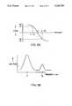
- FIG. 11Aillustrates the color burst portion of a television signal.
- a ringing circuitis used to provide a continuous reference frequency in the periods between the color bursts. Each color burst activates the ringing circuit and the latter continues to resonate at a gradually decreasing amplitude until it is activated by the next color burst. The decay which occurs between color bursts must be small enough that the ringing circuit continues to deliver a reference frequency of sufficient amplitude for the color demodulation circuits.
- VCRvideo cassette recorder
- chromareference color
- a PAL VHS video cassette recordertypically has a chroma phase "jitter" of 15°-25° or more, measured peak-to-peak ( ⁇ 1000 Hz).
- a standard crystal circuit or color burst ringing circuithas a range of only ⁇ 200 Hz and therefore merely locks to average out the phase jitter of the color frequency off the tape rather than following the color phase and frequency faithfully.
- the ringing circuitmust track the incoming burst more accurately than this.
- a wide deviation color frequency oscillator circuitnormally includes a lower frequency (580 KHz) LC oscillator and a stable 3.0 MHz VXCO whose output signals are mixed.
- the upper sideband component from the mixeris selected by a bandpass filter to obtain the 3.58 MHz signal as part of a color burst phase lock loop.
- a 3.58 MHz LC oscillator circuitmay be used with its center frequency stabilized during the vertical blanking interval, as described in U.S. Pat. No. 4,544,943 to Quan, by using a fixed 3.58 MHz crystal oscillator as a reference.
- An LC circuitmay not be used as a color burst ringing circuit (unless stabilized as described above) because the 8-10 cycle color burst (at 3.58 MHz) is repeated at a 15.7 KHz rate, yielding sidebands separated at 15.7 KHz intervals. If an LC ringing circuit drifts by 15.7 KHz or more, it will lock onto an upper or lower sideband (3.58 MHz ⁇ 15.7 KHz) rather than the reference frequency. Thus, a highly stable crystal-based circuit is required for this purpose.
- the frequency range of the oscillatoris broadened by replacing the single crystal with a multiple section bandpass filter containing a plurality of crystal or ceramic elements.
- two or more crystalsare connected in parallel conduction paths.
- the crystalshave resonant frequencies which are at preselected intervals within a desired range.
- crystals having the same resonant frequencymay be used if each of them is connected in series with a capacitor which alters the resonant frequency of the crystal-capacitor combination to one of the preselected frequencies. (Optionally, one of the crystals may be used at its natural frequency without a capacitor.) All of the crystals operate simultaneously.
- the oscillatoris therefore distinguishable from prior art oscillators having multiple crystals which are switched into the circuit one at a time.
- the parallel crystalsare driven by separate transistors.
- the crystalsshare a common current summing node transistor, but have their outputs connected to separate amplifiers.
- the crystalsare driven by separate driving transistors and have their outputs connected to separate amplifiers, whose outputs are then summed.
- the crystalsshare a common driving transistor and have their outputs connected to a single current summing amplifier.
- a multiple section crystal or ceramic bandpass filteris substituted for the arrangement of parallel-connected crystals.
- the phase shift circuit used in the oscillators of this inventionmay include an LC circuit with a variable capacitance (varactor diode), or it may include single pole lead and lag networks.
- An oscillator or ringing circuit in accordance with this inventionis essentially a highly stable oscillating circuit with the equivalent of a lower Q (broader band). Moreover, it may use standard off-the-shelf crystals (AT cut, for example), rather than the more expensive crystals specially cut for use in VXCOs, while providing a greater range of frequency deviation than VXCOs using specially cut crystals.
- AT cutfor example
- FIG. 1illustrates a block diagram of a known crystal oscillator.
- FIG. 2Aillustrates a circuit diagram of the oscillator shown in FIG. 1.
- FIG. 2Billustrates the oscillator of FIG. 2A modified in accordance with this invention.
- FIG. 3Aillustrates the variation of the frequency of a crystal as a function of phase
- FIG. 3Billustrates the variation of its amplitude as a function of frequency.
- FIG. 4illustrates an oscillator according to the invention.
- FIG. 5illustrates a first variation of the oscillator shown in FIG. 4.
- FIG. 6illustrates a second variation of the oscillator shown in FIG. 4.
- FIG. 7illustrates an alternative embodiment according to the invention.
- FIG. 8Aillustrates an oscillator constructed with crystals having the same resonant frequency.
- FIG. 8Billustrates the oscillator of FIG. 8A modified to contain variable capacitors.
- FIG. 9A-9Cillustrate several characteristics of the crystals employed in the oscillators illustrated in FIGS. 4-7.
- FIG. 10Aillustrates a ringing circuit according to the invention.
- FIG. 10Billustrates a more detailed circuit diagram of the ringing circuit shown in FIG. 10A.
- FIG. 11A and 11Billustrate the color burst portion of a television signal, and the response of the ringing circuit of FIG. 10A to the color burst.
- FIG. 12Aillustrates a wide frequency deviation VXCO using the ringing circuit illustrated in FIG. 10A.
- FIG. 12Billustrates the phase shift circuit used in the VXCO of FIG. 12A.
- FIG. 12Cillustrates an alternative embodiment of the VXCO of FIG. 12A which has an even wider frequency range.
- FIG. 13illustrates an alternative form of phase shift circuit.
- FIG. 14illustrates an alternative form of oscillator which includes a multiple section crystal or ceramic bandpass filter.
- FIG. 4illustrates a preferred embodiment according to the invention.
- Oscillator 40is similar to the oscillator illustrated in FIG. 2A, except that an additional driving emitter-follower transistor 25', a crystal 13' and a resistor 12' are connected to driving transistor 25.
- the emitter of driving transistor 25'is connected through a current source 27' to negative supply voltage V EE , and the collector of driving transistor 25' is connected to positive supply voltage V CC .
- Crystals 13 and 13'are driven in phase with each other.
- the varactor diode 20has a relatively low ratio (e.g., 2:1) of maximum to minimum capacitance.
- Prior art oscillatorsrequire capacitance ratios as high as 40:1 (see, e.g., "Survey of Crystal Oscillators", Ham Radio, March 1976, FIGS. 34 and 35).
- the resonant frequencies of crystals 13 and 13', respectively,are selected such that they are spaced at a predetermined interval (e.g., 3 KHz), as shown in FIG. 9A.
- FIG. 9Ashows crystal 13 having a resonant frequency f r and crystal 13' having a resonant frequency f r ', The spurious frequencies f s and f s ' of crystals 13 and 13', respectively, are also shown.
- FIG. 9Billustrates the composite frequency response curve of the combination of crystals 13 and 13' illustrated in FIG. 4 when driven in phase. It is apparent that the curve of FIG. 9B is wider than the curve of FIG.
- the frequencies of the crystalsmust not be spaced too far apart (e.g., for an oscillator having a frequency of around 15 MHz, ideally about 3 KHz, or 200 ppm) or the oscillator will jump from one frequency to another, and will not vary over a continuous band of frequencies between the crystal frequencies.
- FIG. 9Cillustrates a phase versus frequency curve for crystal 13, for crystal 13' and for the composite of crystals 13 and 13'.
- Resistors 12 and 12'function importantly to increase the frequency deviation of crystals 13 and 13' (from f r and f r ' respectively) as a function of phase shift.
- An advantage of the embodiment shown in FIG. 4arises from the fact that crystals 13 and 13' are driven in phase separately by driving transistors 25 and 25', respectively. If transistor 25' were omitted from oscillator 40, by connecting the terminal of crystal 13' to the emitter of transistor 25 (as in FIG. 7, discussed below), the finite output impedance of transistor 25 might allow an interaction between crystals 13 and 13' as the frequency increases.
- the magnitude of resistors 12 and 12'is typically low (150-300 ohms), and with increasing frequency the output impedance of transistor 25 may rise to 20-50 ohms or even more, as the output impedance of transistor 25 increases with frequency due to its finite beta f t .
- crystal 13 and crystal 13'may cause oscillator 40 to jump to the spurious frequency of either crystal as the oscillator tries to change frequency. This phenomenon has been observed empirically and is believed to occur because the currents through crystals 13 and 13' can cause minor voltage variations at the emitter of transistor 25 when the output impedance of transistor 2 is sufficiently high.
- this isolationis achieved by separating the termination paths of the crystal-resistor combinations.
- the terminals of crystals 13 and 13'are both tied to the emitter of driving transistor 25.
- the other side of the series combination of resistor 12' and crystal 13'is linked to the emitter of a summing transistor 26' and through a current source 28' to the negative voltage supply. Because the termination summing paths of crystals 13 and 13' are separate (Via the emitters of summing transistors 26 and 26'), oscillator 50 avoids interaction between crystals 13 and 13' and the consequent problems mentioned above.
- Oscillator 60 shown in FIG. 6exhibits superior isolation between crystals 13 and 13'.
- Crystal 13 and crystal 13'are driven by separate driving transistors 25 and 25' in the manner of oscillator 40 shown in FIG. 4.
- Crystal 13is connected through resistor 12 to the emitter of summing transistor 26, and crystal 13' is connected through resistor 12' to the emitter of summing transistor 26', in the manner of oscillator 50 shown in FIG. 5.
- Oscillator 60is somewhat more expensive to construct, but
- FIG. 4shows (in broken lines) a series combination of a resistor 12", crystal 13" and a driving transistor 25" connected in parallel with the resistor-crystal-transistor combinations described above.
- additional crystalsmay be connected into the embodiments illustrated in FIGS. 5 and 6.
- FIG. 7shows a simplified alternative embodiment according to the invention.
- oscillator 70the combination of resistor 12 and crystal 13 is connected in parallel with the combination of resistor 12' and crystal 13'. This parallel circuit is linked to the emitter of driving transistor 25 and the emitter of transistor 26.
- oscillator 70may show some of the interaction problems between crystals 13 and 13' that were described above. As a result, oscillator 70 is more likely to jump to a spurious frequency than the embodiments described above if the frequency deviation is large. However, oscillator 70 is less expensive to construct than oscillators 40, 50 or 60, and it may show satisfactory performance in certain applications.
- Crystals having the same resonant frequencymay be used if capacitors are connected in series with them.
- An exampleis shown in FIG. 8A, which is identical to FIG. 4 except that oscillator 80 has a capacitor 81 connected to resistor 12 and crystal 13, a capacitor 81' connected to resistor 12' and crystal 13', and a capacitor 81" connected to resistor 12" and crystal 13".
- the values of capacitors 81-81"are selected such that each of the crystal-resistor-capacitor combinations of which they are a part has a desired resonant frequency.
- resistors 12 and 12'each had a resistance of 270 ⁇
- capacitors 81 and 81'had values of 470 pF and 18 pF, respectively
- crystals 13 and 13'had series resonant frequencies of 17.734 MHz.
- a frequency range of +5 KHz to -6 KHzwas obtained, equivalent to -340 ppm to +280 ppm.
- VXCOstypically have frequency ranges of less than ⁇ 170 ppm. (The path containing crystal 13" was not included in the experimental device, but adding more crystals would increase the frequency range further.)
- the frequency range of oscillator 80may be increased further by connecting varactor diodes in place of capacitors 81-81".
- FIG. 8Bshows an oscillator 80B.
- Oscillator 80Bis identical to oscillator 80 except that a varactor diode 81V is connected to resistor 12 and crystal, a varactor diode 81V' is connected to resistor 12' and crystal 13', and a varactor diode 81V" is connected to resistor 12" and crystal 13".
- the capacitance of varactor diodes 81V, 81V' and 81V"are controlled by control voltages V 81V , V 81V , and V 81V" respectively.
- An increased frequency rangeis achieved by varying control voltages V 81V - 81V" in conjunction with V 20 . Control voltages V 81V -V 81V" may actually be linked to V 20 , but this is not necessary.
- FIG. 2Bshows an oscillator 10B which is a modification of the prior art oscillator 10 shown in FIG. 2A.
- Oscillator 10Bincludes a varactor diode 30 connected to resistor 12 and crystal 13. Varactor diode 30 is controlled by a control voltage V 30 . Control voltage V 30 may or may not be linked to V 20 . It has been found that oscillator 10B has a frequency range over 20% broader than oscillator 10 when V 30 and V 20 are tied together.
- the oscillator of this inventionmay be used in a variety of applications where a highly stable, wide range oscillator is required: for example, as a TV monitor subcarrier phase lock loop (PLL) oscillator; as a master clock generator for digital TV processing systems that tracks the frequency of the incoming waveform; and as the incoming tape subcarrier regeneration circuit in demodulation-remodulation and heterodyne color stabilizers.
- PLLphase lock loop
- FIG. 10Aillustrates a color burst ringing circuit 100 in accordance with the invention which has a broad frequency range and is therefore particularly suitable for use with VCRs.
- ringing circuit 100a television signal including color bursts is fed through a burst gate 101 and a voltage amplifier 102.
- the output of amplifier 102is passed to three parallel branches containing crystals 103, 103' and 103", respectively.
- Resistors 104, 104' and 104"are connected to crystals 103, 103', and 103", respectively, and the outputs of crystals 103-103' are delivered to the input terminals of an amplifier 105, which is a high input impedance summing amplifier.
- FIG. 10BA circuit diagram of color burst ringing circuit 100 is illustrated in FIG. 10B.
- the color video (NTSC) signalis delivered to burst gate 101.
- Burst gate 101transmits the color burst when a burst gate signal is present; otherwise burst gate 101 is grounded.
- Voltage amplifier 102includes an emitter-follower transistor 108 which is connected to a current source 109. Amplifier 102 has a gain of 1 and drives the circuitry in the parallel branches containing crystals 103-103".
- Transistors 110, 110' and 110" in amplifier 105are emitter-follower buffers similar to transistor 108, and buffer the voltages across capacitors 106-106", respectively.
- Resistors 111, 111' and 111"are summing resistors, the other sides of which are connected in common to the emitter (input) of a summing amplifier transistor 112. The sum of the outputs of resistors 111-111" appears at the collector of transistor 112. From there it is sent through an emitter-follower transistor 113 to the output of ringing circuit 100.
- Current sources 109 and 114serve to bias transistors 108 and 113, respectively.
- the voltage V B at the base of transistor 112is generally a few volts so that current flows through resistors 111-111" to bias transistors 110-110", respectively.
- Resistors 111-111"are normally equal in value but this need not be the case.
- color burst ringing circuit 100crystal 103 is tuned to the reference frequency f sc ⁇ 3.58 MHz of the color burst signal, crystal 103' is tuned to f sc -1 KHz, and crystal 103" is tuned to f sc +1 KHz.
- the values of resistors 104-104"are in the range of 100-500 ohms.
- Color burst ringing circuit 100is capable of following the expected fluctuations in the frequency of the color burst signal without locking onto the sidebands which are separated by about 15.7 KHz from the 3.58 MHz reference frequency.
- ringing circuit 100receives the color bursts through gate 101, and delivers an output at the output terminal of amplifier 105, which is normally connected to color demodulation circuitry.
- FIG. 11Billustrates the response of ringing circuit 100 to the color bursts in the horizontal blanking interval.
- FIG. 12Aillustrates ringing circuit 100 used in a wide frequency deviation crystal oscillator.
- the circuitry of amplifier 102 and summing amplifier 105are as shown in FIG. 10B.
- the structure of phase shift circuit 120is shown in FIG. 12B.
- the RLC combination of resistor 121, inductance 122 and varactor diode 123has a phase shift of approximately -90°
- Transistors 124 and 125are buffer amplifiers having a gain of 1.
- Amplifier 126is a CMOS inverter or equivalent inverting amplifier which has a phase shift of -180° and a gain much larger than 1.
- phase shift circuit 120has a nominal phase shift of -270°, which can be varied by adjusting the control voltage V 123 delivered to varactor diode 123, and a gain much greater than 1. Since the combination of 103-103" crystals and capacitors 106-106" has a phase shift of -90°, the total phase shift of the oscillator shown in FIG. 12A is close to -360°, and the oscillator has a gain greater than 1. Adjusting the control voltage V 123 delivered to varactor diode 123 changes the phase of phase shift circuit 120 and thereby alters the frequency of the oscillator.
- additional frequency deviation in the oscillator of FIG. 12Amay be obtained by substituting varactor diodes 106V, 106V' and 106V" for fixed capacitors 106, 106' and 106".
- FIG. 13illustrates a phase shift circuit 130 which may be used in place of phase shift circuit 11 (FIG. 2B)
- phase shift circuit 130the combination of a resistor 135 and an inductance 133 provides a lag current to the collector of a transistor 131.
- the combination of a resistor 136 and a capacitor 134provides a lead current to the collector of a transistor 132.
- the collectors of transistors 131 and 132are coupled and passed to an input of a unity gain buffer 137.
- a control voltage V 131is applied to the base of transistor 131. When V 131 is negative, the output has a positive phase shift because transistor 131 is turned off. When V 131 is positive, the output has a negative phase shift because transistor 132 is turned off.
- phase shift circuit 130essentially adds differing amounts of positive and negative phase shift from single pole lead and lag networks. This provides superior linearity of phase versus control voltage as compared with the resonating RLC varactor circuit illustrated in FIG. 12B. This in turn improves the linearity of the oscillator frequency as a function of control voltage. Circuit 130 may also be used in place of phase shift circuit 120 (FIGS. 12A and 12B) if circuit 130 is modified by adding another +90° of phase shift. This can be done by replacing resistor 138 with an inductance. A phase shift network of the kind shown in FIG. 13 is also shown in FIG. 4-20 of the Service Manual for the International Video Corporation IVC-900 Video Tape Recorder (February, 1972).
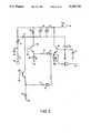
- FIG. 14illustrates an oscillator 140 which includes a multiple section bandpass filter 141.
- Multiple section bandpass filter 141may be either a crystal or ceramic bandpass filter but it must have a phase shift between -180° and +180° in the pass band.
- a 455 KHz multisection ceramic bandpass filtermay be used (e.g., Toko part CFM2, (part number HCFM2-455D) dual (section) resonating element filter).
- Inverters 142 and 143are CMOS inverters which are provided for amplification. Inverters 142 and 143 each provide a phase shift of -180°, or a total of -360° (equivalent to 0° phase shift).
- Oscillator 140also includes phase shift circuits 144 and 145 and a buffer transistor 146.
- phase shift circuits 144 and 145As the phase shift applied by phase shift circuits 144 and 145 is varied by adjusting the control voltages V 144 and V 145 , bandpass filter 141 is forced to an equal but opposite phase shift so that the total phase shift in the oscillator remains at -360° (0°), and thus oscillator 140 moves to a new frequency.
- Two phase shift circuits 144 and 145are included to increase the frequency range of the oscillator, because many multisection crystal and ceramic filters require a phase shift of more than 90° to take advantage of their entire frequency range. (Compare FIG. 9C, which shows a phase shift of 90° to be sufficient to take advantage of the frequency range of a single crystal.) However, a single phase shift circuit may be used in some circumstances. If bandpass filter 141 has a phase shift which is less than -180° or greater than 180° in the pass band, the oscillations of oscillator 140 may stop or power up to an unreliable frequency.
- Phase shift circuits 144 and 145may be either the RLC type illustrated in FIG. 12B or the more linear version illustrated in FIG. 13.
- a multiple section crystal or ceramic bandpass filtermay be substituted for the parallel-connected crystals in the ringing circuit shown in FIG. 10A.
- ceramic resonatorsmay be substituted for the individual crystals in circuits according to this invention.
- the circuits describedmay be further stabilized in frequency against changes in temperature by using temperature compensated capacitors and/or inductances or by superimposing a temperature-dependent voltage on the control voltages provided to the varactor diodes.
- the frequency of a crystal oscillatormay also be varied by changing the control voltages on the varactor diodes (e.g., 81V, 81V' and 81V" in FIG. 8B), while leaving the phase shift circuit at a fixed phase (e.g., 0°).
Landscapes
- Engineering & Computer Science (AREA)
- Multimedia (AREA)
- Signal Processing (AREA)
- Physics & Mathematics (AREA)
- Acoustics & Sound (AREA)
- Oscillators With Electromechanical Resonators (AREA)
Abstract
Description
Claims (57)
Priority Applications (1)
| Application Number | Priority Date | Filing Date | Title |
|---|---|---|---|
| US07/860,643US5229735A (en) | 1992-03-30 | 1992-03-30 | Wide frequency deviation voltage controlled crystal oscillator having plural parallel crystals |
Applications Claiming Priority (1)
| Application Number | Priority Date | Filing Date | Title |
|---|---|---|---|
| US07/860,643US5229735A (en) | 1992-03-30 | 1992-03-30 | Wide frequency deviation voltage controlled crystal oscillator having plural parallel crystals |
Publications (1)
| Publication Number | Publication Date |
|---|---|
| US5229735Atrue US5229735A (en) | 1993-07-20 |
Family
ID=25333673
Family Applications (1)
| Application Number | Title | Priority Date | Filing Date |
|---|---|---|---|
| US07/860,643Expired - LifetimeUS5229735A (en) | 1992-03-30 | 1992-03-30 | Wide frequency deviation voltage controlled crystal oscillator having plural parallel crystals |
Country Status (1)
| Country | Link |
|---|---|
| US (1) | US5229735A (en) |
Cited By (25)
| Publication number | Priority date | Publication date | Assignee | Title |
|---|---|---|---|---|
| US5543756A (en)* | 1995-05-12 | 1996-08-06 | Hewlett-Packard Company | Combined crystal and LC filter |
| EP0794611A1 (en)* | 1996-03-04 | 1997-09-10 | Motorola, Inc. | Method and apparatus for switching crystals in a crystal controlled oscillator |
| WO2002095930A1 (en)* | 2001-05-21 | 2002-11-28 | Thomson Licensing S.A. | Wide band voltage controlled crystal oscillator |
| US6654470B1 (en)* | 1999-07-13 | 2003-11-25 | Fisher-Rosemount Systems, Inc. | Frequency warping for improving resonator signal-to-noise ratio |
| US20070026822A1 (en)* | 2004-10-22 | 2007-02-01 | Sorrells David F | Systems and methods of RF power transmission, modulation, and amplification, including multiple input single output (MISO) amplifiers |
| US20090072663A1 (en)* | 2007-09-19 | 2009-03-19 | Georgia Tech Research Corporation | Single-resonator dual-frequency lateral-extension mode piezoelectric oscillators, and operating methods thereof |
| US20090202215A1 (en)* | 2005-06-27 | 2009-08-13 | Baolin Tan | Copy Protection Method and Apparatus |
| US20100060111A1 (en)* | 2008-09-10 | 2010-03-11 | Farrokh Ayazi | Thin-Film Piezoelectric-on-Insulator Resonators Having Perforated Resonator Bodies Therein |
| US20100194241A1 (en)* | 2009-01-30 | 2010-08-05 | Integrated Device Technology, Inc. | Thin-film bulk acoustic resonators having perforated bodies that provide reduced susceptibility to process-induced lateral dimension variations |
| US20100319185A1 (en)* | 2009-06-19 | 2010-12-23 | Farrokh Ayazi | Methods of Forming Micromechanical Resonators Having High Density Trench Arrays Therein that Provide Passive Temperature Compensation |
| US7885682B2 (en) | 2006-04-24 | 2011-02-08 | Parkervision, Inc. | Systems and methods of RF power transmission, modulation, and amplification, including architectural embodiments of same |
| US7911272B2 (en) | 2007-06-19 | 2011-03-22 | Parkervision, Inc. | Systems and methods of RF power transmission, modulation, and amplification, including blended control embodiments |
| US7932776B2 (en) | 2004-10-22 | 2011-04-26 | Parkervision, Inc. | RF power transmission, modulation, and amplification embodiments |
| US8013675B2 (en) | 2007-06-19 | 2011-09-06 | Parkervision, Inc. | Combiner-less multiple input single output (MISO) amplification with blended control |
| US8031804B2 (en) | 2006-04-24 | 2011-10-04 | Parkervision, Inc. | Systems and methods of RF tower transmission, modulation, and amplification, including embodiments for compensating for waveform distortion |
| US8106724B1 (en) | 2009-07-23 | 2012-01-31 | Integrated Device Technologies, Inc. | Thin-film bulk acoustic resonators having perforated resonator body supports that enhance quality factor |
| US8193869B1 (en)* | 2007-02-15 | 2012-06-05 | Discera, Inc. | Feedthrough capacitance compensation for resonant devices |
| US8315336B2 (en) | 2007-05-18 | 2012-11-20 | Parkervision, Inc. | Systems and methods of RF power transmission, modulation, and amplification, including a switching stage embodiment |
| US8334722B2 (en) | 2007-06-28 | 2012-12-18 | Parkervision, Inc. | Systems and methods of RF power transmission, modulation and amplification |
| US8501515B1 (en) | 2011-02-25 | 2013-08-06 | Integrated Device Technology Inc. | Methods of forming micro-electromechanical resonators using passive compensation techniques |
| US8610336B1 (en) | 2011-09-30 | 2013-12-17 | Integrated Device Technology Inc | Microelectromechanical resonators having resistive heating elements therein configured to provide frequency tuning through convective heating of resonator bodies |
| US8755454B2 (en) | 2011-06-02 | 2014-06-17 | Parkervision, Inc. | Antenna control |
| US9106316B2 (en) | 2005-10-24 | 2015-08-11 | Parkervision, Inc. | Systems and methods of RF power transmission, modulation, and amplification |
| US9608677B2 (en) | 2005-10-24 | 2017-03-28 | Parker Vision, Inc | Systems and methods of RF power transmission, modulation, and amplification |
| US10278131B2 (en) | 2013-09-17 | 2019-04-30 | Parkervision, Inc. | Method, apparatus and system for rendering an information bearing function of time |
Citations (5)
| Publication number | Priority date | Publication date | Assignee | Title |
|---|---|---|---|---|
| DE1045480B (en)* | 1957-04-17 | 1958-12-04 | Pintsch Electro Gmbh | Frequency stabilized oscillator |
| US3170120A (en)* | 1960-09-23 | 1965-02-16 | Garold K Jensen | Active comb filter |
| US3358244A (en)* | 1965-05-03 | 1967-12-12 | Hughes Aircraft Co | Highly linear voltage controlled crystal oscillator |
| US4063194A (en)* | 1975-11-07 | 1977-12-13 | Compagnie D'electronique Et De Piezo-Electricite | Wide-band frequency-controlled crystal oscillator |
| US4994764A (en)* | 1988-11-24 | 1991-02-19 | U.S. Philips Corporation | Single-pin oscillator |
- 1992
- 1992-03-30USUS07/860,643patent/US5229735A/ennot_activeExpired - Lifetime
Patent Citations (5)
| Publication number | Priority date | Publication date | Assignee | Title |
|---|---|---|---|---|
| DE1045480B (en)* | 1957-04-17 | 1958-12-04 | Pintsch Electro Gmbh | Frequency stabilized oscillator |
| US3170120A (en)* | 1960-09-23 | 1965-02-16 | Garold K Jensen | Active comb filter |
| US3358244A (en)* | 1965-05-03 | 1967-12-12 | Hughes Aircraft Co | Highly linear voltage controlled crystal oscillator |
| US4063194A (en)* | 1975-11-07 | 1977-12-13 | Compagnie D'electronique Et De Piezo-Electricite | Wide-band frequency-controlled crystal oscillator |
| US4994764A (en)* | 1988-11-24 | 1991-02-19 | U.S. Philips Corporation | Single-pin oscillator |
Non-Patent Citations (6)
| Title |
|---|
| "Survey of Crystal Oscillators", Roger Harrison, Ham Radio, Mar. 1976, pp. 10-22. |
| Handbook of Filter Synthesis , A. I. Zverev, John Wiley & Sons, Inc., 1967, pp. 425, 426, 446, 452, 486 487.* |
| Handbook of Filter Synthesis, A. I. Zverev, John Wiley & Sons, Inc., 1967, pp. 425, 426, 446, 452, 486-487. |
| Science Manual Video Tape Recorder , IVC 900, International Video Corp., Feb. 1972, pp. 4 30.* |
| Science Manual--Video Tape Recorder, IVC-900, International Video Corp., Feb. 1972, pp. 4-30. |
| Survey of Crystal Oscillators , Roger Harrison, Ham Radio , Mar. 1976, pp. 10 22.* |
Cited By (78)
| Publication number | Priority date | Publication date | Assignee | Title |
|---|---|---|---|---|
| US5543756A (en)* | 1995-05-12 | 1996-08-06 | Hewlett-Packard Company | Combined crystal and LC filter |
| EP0794611A1 (en)* | 1996-03-04 | 1997-09-10 | Motorola, Inc. | Method and apparatus for switching crystals in a crystal controlled oscillator |
| KR100460813B1 (en)* | 1996-03-04 | 2005-06-02 | 모토로라 인코포레이티드 | Multi Crystal Control Oscillator |
| US6654470B1 (en)* | 1999-07-13 | 2003-11-25 | Fisher-Rosemount Systems, Inc. | Frequency warping for improving resonator signal-to-noise ratio |
| US7180382B2 (en) | 2001-05-21 | 2007-02-20 | Thomson Licensing | Wide band voltage controlled crystal oscillator |
| WO2002095930A1 (en)* | 2001-05-21 | 2002-11-28 | Thomson Licensing S.A. | Wide band voltage controlled crystal oscillator |
| US20040130405A1 (en)* | 2001-05-21 | 2004-07-08 | Chandra Mohan | Wide band voltage controlled crystal oscillator |
| US8639196B2 (en) | 2004-10-22 | 2014-01-28 | Parkervision, Inc. | Control modules |
| US9166528B2 (en) | 2004-10-22 | 2015-10-20 | Parkervision, Inc. | RF power transmission, modulation, and amplification embodiments |
| US9768733B2 (en) | 2004-10-22 | 2017-09-19 | Parker Vision, Inc. | Multiple input single output device with vector signal and bias signal inputs |
| US20070178859A1 (en)* | 2004-10-22 | 2007-08-02 | Parkervision, Inc. | Systems and methods of RF power transmission, modulation, and amplification, including cartesian 4-branch embodiments |
| US8433264B2 (en) | 2004-10-22 | 2013-04-30 | Parkervision, Inc. | Multiple input single output (MISO) amplifier having multiple transistors whose output voltages substantially equal the amplifier output voltage |
| US8233858B2 (en) | 2004-10-22 | 2012-07-31 | Parkervision, Inc. | RF power transmission, modulation, and amplification embodiments, including control circuitry for controlling power amplifier output stages |
| US20100119010A1 (en)* | 2004-10-22 | 2010-05-13 | Parkervision, Inc. | Control Modules |
| US8280321B2 (en) | 2004-10-22 | 2012-10-02 | Parkervision, Inc. | Systems and methods of RF power transmission, modulation, and amplification, including Cartesian-Polar-Cartesian-Polar (CPCP) embodiments |
| US8351870B2 (en)* | 2004-10-22 | 2013-01-08 | Parkervision, Inc. | Systems and methods of RF power transmission, modulation, and amplification, including cartesian 4-branch embodiments |
| US7835709B2 (en) | 2004-10-22 | 2010-11-16 | Parkervision, Inc. | RF power transmission, modulation, and amplification using multiple input single output (MISO) amplifiers to process phase angle and magnitude information |
| US7844235B2 (en) | 2004-10-22 | 2010-11-30 | Parkervision, Inc. | RF power transmission, modulation, and amplification, including harmonic control embodiments |
| US9197164B2 (en) | 2004-10-22 | 2015-11-24 | Parkervision, Inc. | RF power transmission, modulation, and amplification, including direct cartesian 2-branch embodiments |
| US9197163B2 (en) | 2004-10-22 | 2015-11-24 | Parkvision, Inc. | Systems, and methods of RF power transmission, modulation, and amplification, including embodiments for output stage protection |
| US8428527B2 (en) | 2004-10-22 | 2013-04-23 | Parkervision, Inc. | RF power transmission, modulation, and amplification, including direct cartesian 2-branch embodiments |
| US9143088B2 (en) | 2004-10-22 | 2015-09-22 | Parkervision, Inc. | Control modules |
| US8626093B2 (en) | 2004-10-22 | 2014-01-07 | Parkervision, Inc. | RF power transmission, modulation, and amplification embodiments |
| US7932776B2 (en) | 2004-10-22 | 2011-04-26 | Parkervision, Inc. | RF power transmission, modulation, and amplification embodiments |
| US8406711B2 (en) | 2004-10-22 | 2013-03-26 | Parkervision, Inc. | Systems and methods of RF power transmission, modulation, and amplification, including a Cartesian-Polar-Cartesian-Polar (CPCP) embodiment |
| US8913974B2 (en) | 2004-10-22 | 2014-12-16 | Parkervision, Inc. | RF power transmission, modulation, and amplification, including direct cartesian 2-branch embodiments |
| US7945224B2 (en) | 2004-10-22 | 2011-05-17 | Parkervision, Inc. | Systems and methods of RF power transmission, modulation, and amplification, including waveform distortion compensation embodiments |
| US8781418B2 (en) | 2004-10-22 | 2014-07-15 | Parkervision, Inc. | Power amplification based on phase angle controlled reference signal and amplitude control signal |
| US20070026822A1 (en)* | 2004-10-22 | 2007-02-01 | Sorrells David F | Systems and methods of RF power transmission, modulation, and amplification, including multiple input single output (MISO) amplifiers |
| US8577313B2 (en) | 2004-10-22 | 2013-11-05 | Parkervision, Inc. | Systems and methods of RF power transmission, modulation, and amplification, including output stage protection circuitry |
| US8447248B2 (en) | 2004-10-22 | 2013-05-21 | Parkervision, Inc. | RF power transmission, modulation, and amplification, including power control of multiple input single output (MISO) amplifiers |
| US8498519B2 (en)* | 2005-06-27 | 2013-07-30 | Dcs Copy Protection Ltd. | Copy protection method and apparatus |
| US20090202215A1 (en)* | 2005-06-27 | 2009-08-13 | Baolin Tan | Copy Protection Method and Apparatus |
| US9419692B2 (en) | 2005-10-24 | 2016-08-16 | Parkervision, Inc. | Antenna control |
| US9094085B2 (en) | 2005-10-24 | 2015-07-28 | Parkervision, Inc. | Control of MISO node |
| US9106316B2 (en) | 2005-10-24 | 2015-08-11 | Parkervision, Inc. | Systems and methods of RF power transmission, modulation, and amplification |
| US9608677B2 (en) | 2005-10-24 | 2017-03-28 | Parker Vision, Inc | Systems and methods of RF power transmission, modulation, and amplification |
| US9614484B2 (en) | 2005-10-24 | 2017-04-04 | Parkervision, Inc. | Systems and methods of RF power transmission, modulation, and amplification, including control functions to transition an output of a MISO device |
| US9705540B2 (en) | 2005-10-24 | 2017-07-11 | Parker Vision, Inc. | Control of MISO node |
| US7937106B2 (en) | 2006-04-24 | 2011-05-03 | ParkerVision, Inc, | Systems and methods of RF power transmission, modulation, and amplification, including architectural embodiments of same |
| US8050353B2 (en) | 2006-04-24 | 2011-11-01 | Parkervision, Inc. | Systems and methods of RF power transmission, modulation, and amplification, including embodiments for compensating for waveform distortion |
| US7885682B2 (en) | 2006-04-24 | 2011-02-08 | Parkervision, Inc. | Systems and methods of RF power transmission, modulation, and amplification, including architectural embodiments of same |
| US7949365B2 (en) | 2006-04-24 | 2011-05-24 | Parkervision, Inc. | Systems and methods of RF power transmission, modulation, and amplification, including architectural embodiments of same |
| US9106500B2 (en) | 2006-04-24 | 2015-08-11 | Parkervision, Inc. | Systems and methods of RF power transmission, modulation, and amplification, including embodiments for error correction |
| US8059749B2 (en) | 2006-04-24 | 2011-11-15 | Parkervision, Inc. | Systems and methods of RF power transmission, modulation, and amplification, including embodiments for compensating for waveform distortion |
| US7929989B2 (en) | 2006-04-24 | 2011-04-19 | Parkervision, Inc. | Systems and methods of RF power transmission, modulation, and amplification, including architectural embodiments of same |
| US8026764B2 (en) | 2006-04-24 | 2011-09-27 | Parkervision, Inc. | Generation and amplification of substantially constant envelope signals, including switching an output among a plurality of nodes |
| US8036306B2 (en) | 2006-04-24 | 2011-10-11 | Parkervision, Inc. | Systems and methods of RF power transmission, modulation and amplification, including embodiments for compensating for waveform distortion |
| US8031804B2 (en) | 2006-04-24 | 2011-10-04 | Parkervision, Inc. | Systems and methods of RF tower transmission, modulation, and amplification, including embodiments for compensating for waveform distortion |
| US8913691B2 (en) | 2006-08-24 | 2014-12-16 | Parkervision, Inc. | Controlling output power of multiple-input single-output (MISO) device |
| US8193869B1 (en)* | 2007-02-15 | 2012-06-05 | Discera, Inc. | Feedthrough capacitance compensation for resonant devices |
| US8315336B2 (en) | 2007-05-18 | 2012-11-20 | Parkervision, Inc. | Systems and methods of RF power transmission, modulation, and amplification, including a switching stage embodiment |
| US8548093B2 (en) | 2007-05-18 | 2013-10-01 | Parkervision, Inc. | Power amplification based on frequency control signal |
| US8461924B2 (en) | 2007-06-19 | 2013-06-11 | Parkervision, Inc. | Systems and methods of RF power transmission, modulation, and amplification, including embodiments for controlling a transimpedance node |
| US8013675B2 (en) | 2007-06-19 | 2011-09-06 | Parkervision, Inc. | Combiner-less multiple input single output (MISO) amplification with blended control |
| US7911272B2 (en) | 2007-06-19 | 2011-03-22 | Parkervision, Inc. | Systems and methods of RF power transmission, modulation, and amplification, including blended control embodiments |
| US8410849B2 (en) | 2007-06-19 | 2013-04-02 | Parkervision, Inc. | Systems and methods of RF power transmission, modulation, and amplification, including blended control embodiments |
| US8766717B2 (en) | 2007-06-19 | 2014-07-01 | Parkervision, Inc. | Systems and methods of RF power transmission, modulation, and amplification, including varying weights of control signals |
| US8502600B2 (en) | 2007-06-19 | 2013-08-06 | Parkervision, Inc. | Combiner-less multiple input single output (MISO) amplification with blended control |
| US8884694B2 (en) | 2007-06-28 | 2014-11-11 | Parkervision, Inc. | Systems and methods of RF power transmission, modulation, and amplification |
| US8334722B2 (en) | 2007-06-28 | 2012-12-18 | Parkervision, Inc. | Systems and methods of RF power transmission, modulation and amplification |
| US7800282B2 (en) | 2007-09-19 | 2010-09-21 | Integrated Device Technology, Inc. | Single-resonator dual-frequency lateral-extension mode piezoelectric oscillators, and operating methods thereof |
| WO2009038736A3 (en)* | 2007-09-19 | 2009-08-06 | Georgia Tech Res Inst | Single-resonator dual-frequency lateral-extension mode piezoelectric oscillators, and operating methods thereof |
| US20090072663A1 (en)* | 2007-09-19 | 2009-03-19 | Georgia Tech Research Corporation | Single-resonator dual-frequency lateral-extension mode piezoelectric oscillators, and operating methods thereof |
| US8242663B2 (en) | 2008-09-10 | 2012-08-14 | Georgia Tech Research Corporation | Oscillator having micro-electromechanical resonators and driver circuits therein that support in-phase and out-of-phase signals |
| US20110133848A1 (en)* | 2008-09-10 | 2011-06-09 | Farrokh Ayazi | Thin-Film Piezoelectric-on-Insulator Resonators Having Perforated Resonator Bodies Therein |
| US20100060111A1 (en)* | 2008-09-10 | 2010-03-11 | Farrokh Ayazi | Thin-Film Piezoelectric-on-Insulator Resonators Having Perforated Resonator Bodies Therein |
| US7888843B2 (en) | 2008-09-10 | 2011-02-15 | Georgia Tech Research Corporation | Thin-film piezoelectric-on-insulator resonators having perforated resonator bodies therein |
| US20100194241A1 (en)* | 2009-01-30 | 2010-08-05 | Integrated Device Technology, Inc. | Thin-film bulk acoustic resonators having perforated bodies that provide reduced susceptibility to process-induced lateral dimension variations |
| US7939990B2 (en) | 2009-01-30 | 2011-05-10 | Integrated Device Technology, Inc. | Thin-film bulk acoustic resonators having perforated bodies that provide reduced susceptibility to process-induced lateral dimension variations |
| US8381378B2 (en) | 2009-06-19 | 2013-02-26 | Georgia Tech Research Corporation | Methods of forming micromechanical resonators having high density trench arrays therein that provide passive temperature compensation |
| US20100319185A1 (en)* | 2009-06-19 | 2010-12-23 | Farrokh Ayazi | Methods of Forming Micromechanical Resonators Having High Density Trench Arrays Therein that Provide Passive Temperature Compensation |
| US8106724B1 (en) | 2009-07-23 | 2012-01-31 | Integrated Device Technologies, Inc. | Thin-film bulk acoustic resonators having perforated resonator body supports that enhance quality factor |
| US8785229B1 (en) | 2011-02-25 | 2014-07-22 | Integrated Device Technology, Inc. | Methods of forming micro-electromechanical resonators having passive temperature compensation regions therein |
| US8501515B1 (en) | 2011-02-25 | 2013-08-06 | Integrated Device Technology Inc. | Methods of forming micro-electromechanical resonators using passive compensation techniques |
| US8755454B2 (en) | 2011-06-02 | 2014-06-17 | Parkervision, Inc. | Antenna control |
| US8610336B1 (en) | 2011-09-30 | 2013-12-17 | Integrated Device Technology Inc | Microelectromechanical resonators having resistive heating elements therein configured to provide frequency tuning through convective heating of resonator bodies |
| US10278131B2 (en) | 2013-09-17 | 2019-04-30 | Parkervision, Inc. | Method, apparatus and system for rendering an information bearing function of time |
Similar Documents
| Publication | Publication Date | Title |
|---|---|---|
| US5229735A (en) | Wide frequency deviation voltage controlled crystal oscillator having plural parallel crystals | |
| EP0660504B1 (en) | Oscillator circuit | |
| US4131862A (en) | Phase lock loop with narrow band lock-in and wideband acquisition characteristics | |
| US4347484A (en) | Synthesizer having an injection synchronized divider | |
| EP0432052B1 (en) | RF modulator | |
| JP2729028B2 (en) | Method and circuit for demodulating FM carrier | |
| US4134085A (en) | Narrow deviation voltage controlled crystal oscillator for mobile radio | |
| CA2154811C (en) | Fast acting control system | |
| US4550293A (en) | Narrow deviation voltage controlled crystal oscillator | |
| US3806828A (en) | Combined high-frequency bias generator and amplifier for recording systems | |
| US4243953A (en) | Voltage controlled oscillator presenting high impedance to parallel resonant tank circuit | |
| US20030112080A1 (en) | Temperature compensation device and electronic apparatus comprising such a device | |
| JP2541559B2 (en) | Clock signal regenerator | |
| US4633316A (en) | Stable low cost 4.5 MHz remodulator | |
| EP0639893B1 (en) | Negative feedback control circuit having a common line for input and output signals | |
| US6181217B1 (en) | VCXO with reduced PWM effects high slew rate conditions | |
| US4081766A (en) | Crystal tuned voltage controlled oscillator | |
| EP0140429B1 (en) | Voltage controlled oscillator | |
| US4366451A (en) | Chrominance subcarrier regeneration network | |
| JPS59100604A (en) | Oscillator | |
| US4620226A (en) | Apparatus for producing audio and visual signals for modulating a television system carrier signal | |
| JPH0241934B2 (en) | ||
| US4904962A (en) | Gated high stability LC stabilized oscillator | |
| US4346351A (en) | High frequency voltage-controlled oscillator | |
| US3030585A (en) | Frequency-modulation detector circuit |
Legal Events
| Date | Code | Title | Description |
|---|---|---|---|
| AS | Assignment | Owner name:MACROVISION CORPORATION A CORPORATION OF DELAWA Free format text:ASSIGNMENT OF ASSIGNORS INTEREST.;ASSIGNOR:QUAN, RONALD;REEL/FRAME:006092/0039 Effective date:19920326 | |
| STCF | Information on status: patent grant | Free format text:PATENTED CASE | |
| FPAY | Fee payment | Year of fee payment:4 | |
| FEPP | Fee payment procedure | Free format text:PAYOR NUMBER ASSIGNED (ORIGINAL EVENT CODE: ASPN); ENTITY STATUS OF PATENT OWNER: LARGE ENTITY | |
| FEPP | Fee payment procedure | Free format text:PAT HLDR NO LONGER CLAIMS SMALL ENT STAT AS SMALL BUSINESS (ORIGINAL EVENT CODE: LSM2); ENTITY STATUS OF PATENT OWNER: LARGE ENTITY | |
| FPAY | Fee payment | Year of fee payment:8 | |
| FPAY | Fee payment | Year of fee payment:12 | |
| AS | Assignment | Owner name:JPMORGAN CHASE BANK, N.A., NEW YORK Free format text:SECURITY AGREEMENT;ASSIGNORS:APTIV DIGITAL, INC.;GEMSTAR DEVELOPMENT CORPORATION;GEMSTAR-TV GUIDE INTERNATIONAL, INC.;AND OTHERS;REEL/FRAME:020986/0074 Effective date:20080502 Owner name:JPMORGAN CHASE BANK, N.A.,NEW YORK Free format text:SECURITY AGREEMENT;ASSIGNORS:APTIV DIGITAL, INC.;GEMSTAR DEVELOPMENT CORPORATION;GEMSTAR-TV GUIDE INTERNATIONAL, INC.;AND OTHERS;REEL/FRAME:020986/0074 Effective date:20080502 | |
| AS | Assignment | Owner name:STARSIGHT TELECAST, INC., CALIFORNIA Free format text:RELEASE BY SECURED PARTY;ASSIGNOR:JPMORGAN CHASE BANK, N.A. (A NATIONAL ASSOCIATION);REEL/FRAME:025222/0731 Effective date:20100317 Owner name:ROVI SOLUTIONS CORPORATION (FORMERLY KNOWN AS MACR Free format text:RELEASE BY SECURED PARTY;ASSIGNOR:JPMORGAN CHASE BANK, N.A. (A NATIONAL ASSOCIATION);REEL/FRAME:025222/0731 Effective date:20100317 Owner name:ODS PROPERTIES, INC., CALIFORNIA Free format text:RELEASE BY SECURED PARTY;ASSIGNOR:JPMORGAN CHASE BANK, N.A. (A NATIONAL ASSOCIATION);REEL/FRAME:025222/0731 Effective date:20100317 Owner name:INDEX SYSTEMS INC., CALIFORNIA Free format text:RELEASE BY SECURED PARTY;ASSIGNOR:JPMORGAN CHASE BANK, N.A. (A NATIONAL ASSOCIATION);REEL/FRAME:025222/0731 Effective date:20100317 Owner name:ROVI SOLUTIONS LIMITED (FORMERLY KNOWN AS MACROVIS Free format text:RELEASE BY SECURED PARTY;ASSIGNOR:JPMORGAN CHASE BANK, N.A. (A NATIONAL ASSOCIATION);REEL/FRAME:025222/0731 Effective date:20100317 Owner name:ROVI DATA SOLUTIONS, INC. (FORMERLY KNOWN AS TV GU Free format text:RELEASE BY SECURED PARTY;ASSIGNOR:JPMORGAN CHASE BANK, N.A. (A NATIONAL ASSOCIATION);REEL/FRAME:025222/0731 Effective date:20100317 Owner name:UNITED VIDEO PROPERTIES, INC., CALIFORNIA Free format text:RELEASE BY SECURED PARTY;ASSIGNOR:JPMORGAN CHASE BANK, N.A. (A NATIONAL ASSOCIATION);REEL/FRAME:025222/0731 Effective date:20100317 Owner name:GEMSTAR DEVELOPMENT CORPORATION, CALIFORNIA Free format text:RELEASE BY SECURED PARTY;ASSIGNOR:JPMORGAN CHASE BANK, N.A. (A NATIONAL ASSOCIATION);REEL/FRAME:025222/0731 Effective date:20100317 Owner name:TV GUIDE ONLINE, LLC, CALIFORNIA Free format text:RELEASE BY SECURED PARTY;ASSIGNOR:JPMORGAN CHASE BANK, N.A. (A NATIONAL ASSOCIATION);REEL/FRAME:025222/0731 Effective date:20100317 Owner name:APTIV DIGITAL, INC., CALIFORNIA Free format text:RELEASE BY SECURED PARTY;ASSIGNOR:JPMORGAN CHASE BANK, N.A. (A NATIONAL ASSOCIATION);REEL/FRAME:025222/0731 Effective date:20100317 Owner name:ROVI GUIDES, INC. (FORMERLY KNOWN AS GEMSTAR-TV GU Free format text:RELEASE BY SECURED PARTY;ASSIGNOR:JPMORGAN CHASE BANK, N.A. (A NATIONAL ASSOCIATION);REEL/FRAME:025222/0731 Effective date:20100317 Owner name:ALL MEDIA GUIDE, LLC, CALIFORNIA Free format text:RELEASE BY SECURED PARTY;ASSIGNOR:JPMORGAN CHASE BANK, N.A. (A NATIONAL ASSOCIATION);REEL/FRAME:025222/0731 Effective date:20100317 Owner name:ROVI TECHNOLOGIES CORPORATION, CALIFORNIA Free format text:RELEASE BY SECURED PARTY;ASSIGNOR:JPMORGAN CHASE BANK, N.A. (A NATIONAL ASSOCIATION);REEL/FRAME:025222/0731 Effective date:20100317 Owner name:TV GUIDE, INC., CALIFORNIA Free format text:RELEASE BY SECURED PARTY;ASSIGNOR:JPMORGAN CHASE BANK, N.A. (A NATIONAL ASSOCIATION);REEL/FRAME:025222/0731 Effective date:20100317 | |
| AS | Assignment | Owner name:JPMORGAN CHASE BANK, N.A., AS COLLATERAL AGENT, NE Free format text:SECURITY INTEREST;ASSIGNORS:APTIV DIGITAL, INC., A DELAWARE CORPORATION;GEMSTAR DEVELOPMENT CORPORATION, A CALIFORNIA CORPORATION;INDEX SYSTEMS INC, A BRITISH VIRGIN ISLANDS COMPANY;AND OTHERS;REEL/FRAME:027039/0168 Effective date:20110913 | |
| AS | Assignment | Owner name:STARSIGHT TELECAST, INC., CALIFORNIA Free format text:PATENT RELEASE;ASSIGNOR:JPMORGAN CHASE BANK, N.A., AS COLLATERAL AGENT;REEL/FRAME:033396/0001 Effective date:20140702 Owner name:ROVI SOLUTIONS CORPORATION, CALIFORNIA Free format text:PATENT RELEASE;ASSIGNOR:JPMORGAN CHASE BANK, N.A., AS COLLATERAL AGENT;REEL/FRAME:033396/0001 Effective date:20140702 Owner name:INDEX SYSTEMS INC., CALIFORNIA Free format text:PATENT RELEASE;ASSIGNOR:JPMORGAN CHASE BANK, N.A., AS COLLATERAL AGENT;REEL/FRAME:033396/0001 Effective date:20140702 Owner name:ROVI GUIDES, INC., CALIFORNIA Free format text:PATENT RELEASE;ASSIGNOR:JPMORGAN CHASE BANK, N.A., AS COLLATERAL AGENT;REEL/FRAME:033396/0001 Effective date:20140702 Owner name:ALL MEDIA GUIDE, LLC, CALIFORNIA Free format text:PATENT RELEASE;ASSIGNOR:JPMORGAN CHASE BANK, N.A., AS COLLATERAL AGENT;REEL/FRAME:033396/0001 Effective date:20140702 Owner name:ROVI TECHNOLOGIES CORPORATION, CALIFORNIA Free format text:PATENT RELEASE;ASSIGNOR:JPMORGAN CHASE BANK, N.A., AS COLLATERAL AGENT;REEL/FRAME:033396/0001 Effective date:20140702 Owner name:ROVI CORPORATION, CALIFORNIA Free format text:PATENT RELEASE;ASSIGNOR:JPMORGAN CHASE BANK, N.A., AS COLLATERAL AGENT;REEL/FRAME:033396/0001 Effective date:20140702 Owner name:GEMSTAR DEVELOPMENT CORPORATION, CALIFORNIA Free format text:PATENT RELEASE;ASSIGNOR:JPMORGAN CHASE BANK, N.A., AS COLLATERAL AGENT;REEL/FRAME:033396/0001 Effective date:20140702 Owner name:APTIV DIGITAL, INC., CALIFORNIA Free format text:PATENT RELEASE;ASSIGNOR:JPMORGAN CHASE BANK, N.A., AS COLLATERAL AGENT;REEL/FRAME:033396/0001 Effective date:20140702 Owner name:TV GUIDE INTERNATIONAL, INC., CALIFORNIA Free format text:PATENT RELEASE;ASSIGNOR:JPMORGAN CHASE BANK, N.A., AS COLLATERAL AGENT;REEL/FRAME:033396/0001 Effective date:20140702 Owner name:UNITED VIDEO PROPERTIES, INC., CALIFORNIA Free format text:PATENT RELEASE;ASSIGNOR:JPMORGAN CHASE BANK, N.A., AS COLLATERAL AGENT;REEL/FRAME:033396/0001 Effective date:20140702 |