US5228450A - Methods and apparatus for ambulatory physiological monitoring - Google Patents
Methods and apparatus for ambulatory physiological monitoringDownload PDFInfo
- Publication number
- US5228450A US5228450AUS07/695,600US69560091AUS5228450AUS 5228450 AUS5228450 AUS 5228450AUS 69560091 AUS69560091 AUS 69560091AUS 5228450 AUS5228450 AUS 5228450A
- Authority
- US
- United States
- Prior art keywords
- data
- ambulatory
- electrocardiography
- physiological
- patient
- Prior art date
- Legal status (The legal status is an assumption and is not a legal conclusion. Google has not performed a legal analysis and makes no representation as to the accuracy of the status listed.)
- Expired - Fee Related
Links
- 238000000034methodMethods0.000titleclaimsdescription12
- 238000012544monitoring processMethods0.000titledescription16
- 238000002565electrocardiographyMethods0.000claimsabstractdescription98
- 239000000872bufferSubstances0.000claimsabstractdescription59
- 230000004044responseEffects0.000claimsabstractdescription10
- 230000004913activationEffects0.000claimsabstractdescription5
- 230000015654memoryEffects0.000claimsdescription27
- 238000005070samplingMethods0.000claimsdescription14
- 238000004458analytical methodMethods0.000claimsdescription7
- 238000003745diagnosisMethods0.000claims8
- 238000012546transferMethods0.000description20
- 102100026827Protein associated with UVRAG as autophagy enhancerHuman genes0.000description14
- 101710102978Protein associated with UVRAG as autophagy enhancerProteins0.000description14
- 238000012545processingMethods0.000description14
- 238000012360testing methodMethods0.000description10
- 238000010586diagramMethods0.000description6
- 230000008569processEffects0.000description6
- 239000007787solidSubstances0.000description6
- 230000001960triggered effectEffects0.000description5
- 238000007906compressionMethods0.000description4
- 230000006835compressionEffects0.000description4
- 238000011084recoveryMethods0.000description4
- 238000004891communicationMethods0.000description3
- 238000001514detection methodMethods0.000description3
- 238000013144data compressionMethods0.000description2
- 230000006870functionEffects0.000description2
- WABPQHHGFIMREM-UHFFFAOYSA-Nlead(0)Chemical compound[Pb]WABPQHHGFIMREM-UHFFFAOYSA-N0.000description2
- 239000004973liquid crystal related substanceSubstances0.000description2
- 230000003068static effectEffects0.000description2
- 230000026676system processEffects0.000description2
- 0C=CCNCC1C(C(C*(C2)=C)=C)=C2C11CCC1Chemical compoundC=CCNCC1C(C(C*(C2)=C)=C)=C2C11CCC10.000description1
- 206010008479Chest PainDiseases0.000description1
- 102100031699Choline transporter-like protein 1Human genes0.000description1
- 102100035954Choline transporter-like protein 2Human genes0.000description1
- 102100039497Choline transporter-like protein 3Human genes0.000description1
- 101000940912Homo sapiens Choline transporter-like protein 1Proteins0.000description1
- 101000948115Homo sapiens Choline transporter-like protein 2Proteins0.000description1
- 101000889279Homo sapiens Choline transporter-like protein 3Proteins0.000description1
- 229910021607Silver chlorideInorganic materials0.000description1
- 230000005856abnormalityEffects0.000description1
- 238000013459approachMethods0.000description1
- 230000005540biological transmissionEffects0.000description1
- 230000036772blood pressureEffects0.000description1
- 206010061592cardiac fibrillationDiseases0.000description1
- 230000008602contractionEffects0.000description1
- 239000013078crystalSubstances0.000description1
- 230000000694effectsEffects0.000description1
- 230000002600fibrillogenic effectEffects0.000description1
- 230000036541healthEffects0.000description1
- 239000000463materialSubstances0.000description1
- 230000002093peripheral effectEffects0.000description1
- 230000002028prematureEffects0.000description1
- 230000035939shockEffects0.000description1
- HKZLPVFGJNLROG-UHFFFAOYSA-Msilver monochlorideChemical compound[Cl-].[Ag+]HKZLPVFGJNLROG-UHFFFAOYSA-M0.000description1
- 230000002861ventricularEffects0.000description1
Images


Classifications
- A—HUMAN NECESSITIES
- A61—MEDICAL OR VETERINARY SCIENCE; HYGIENE
- A61B—DIAGNOSIS; SURGERY; IDENTIFICATION
- A61B5/00—Measuring for diagnostic purposes; Identification of persons
- A61B5/24—Detecting, measuring or recording bioelectric or biomagnetic signals of the body or parts thereof
- A61B5/316—Modalities, i.e. specific diagnostic methods
- A61B5/318—Heart-related electrical modalities, e.g. electrocardiography [ECG]
- A61B5/333—Recording apparatus specially adapted therefor
- A61B5/336—Magnetic recording apparatus
- A—HUMAN NECESSITIES
- A61—MEDICAL OR VETERINARY SCIENCE; HYGIENE
- A61B—DIAGNOSIS; SURGERY; IDENTIFICATION
- A61B5/00—Measuring for diagnostic purposes; Identification of persons
- A61B5/24—Detecting, measuring or recording bioelectric or biomagnetic signals of the body or parts thereof
- A61B5/30—Input circuits therefor
- A61B5/303—Patient cord assembly, e.g. cable harness
- A—HUMAN NECESSITIES
- A61—MEDICAL OR VETERINARY SCIENCE; HYGIENE
- A61B—DIAGNOSIS; SURGERY; IDENTIFICATION
- A61B5/00—Measuring for diagnostic purposes; Identification of persons
- A61B5/24—Detecting, measuring or recording bioelectric or biomagnetic signals of the body or parts thereof
- A61B5/30—Input circuits therefor
- A61B5/307—Input circuits therefor specially adapted for particular uses
- A61B5/308—Input circuits therefor specially adapted for particular uses for electrocardiography [ECG]
- A—HUMAN NECESSITIES
- A61—MEDICAL OR VETERINARY SCIENCE; HYGIENE
- A61B—DIAGNOSIS; SURGERY; IDENTIFICATION
- A61B5/00—Measuring for diagnostic purposes; Identification of persons
- A61B5/24—Detecting, measuring or recording bioelectric or biomagnetic signals of the body or parts thereof
- A61B5/316—Modalities, i.e. specific diagnostic methods
- A61B5/318—Heart-related electrical modalities, e.g. electrocardiography [ECG]
- A61B5/332—Portable devices specially adapted therefor
Definitions
- This inventionrelates generally to patient monitoring systems and, more particularly, to ambulatory electrocardiography (ECG) monitors.
- ECGelectrocardiography
- ECG monitoringhas become a useful tool in monitoring the health of a patient's heart.
- a prominent type of ECG monitoringis Holter monitoring in which ECG data is acquired continuously over a 24 hour period. Data acquired by Holter monitoring is useful in identifying patients who are at risk of ventricular tachycadia.
- Late potentialsare low level electrical signals that cause late activation of the heart within its cycle. Such late potentials can cause premature contraction and, eventually, severe fibrillation.
- Such late potentialshave been difficult to detect because they are of too low a level (i.e., approximately 5 microvolts) and too high a frequency (i.e., approximately 250 hertz) for detection by conventional Holter monitoring systems.
- ECG Holter monitoring systemshave generally fallen into two categories: solid state systems and tape based systems. Both types of systems are referred to as ambulatory systems because they are worn by a patient outside the hospital during the patient's normal daily routine.
- the tape based systemsare provided with a magnetic tape recorder that records ECG signals acquired from electrodes that are attached at specific locations on the patient. When the 24 hour period has expired, the tape is removed from the monitor unit and the ECG signals stored therein are analyzed.
- Such tape based systemssuffer three primary drawbacks.
- Theyhave a limited frequency response. This limitation stems primarily from the limited speed of operation of the tapes which limits the frequency band of ECG signals stored on the tape in a given time frame.
- the tapeshave to move slowly so as to ensure that there is sufficient tape to record the ECG signals for the entire 24 hour monitoring.
- the tape unitstypically move at a rate in the range of one millimeter per second.
- the highest frequency responseis limited by the small record zone size on the tape, which also limits the frequency band of ECG signals stored on the tape. In general, such systems can operate, at best, up to a maximum frequency of 40 hertz.
- a second problem suffered with such tape based systemsis tape motion error problems.
- Solid state unitsgenerally utilize a memory such as a RAM built into the monitor unit.
- Solid state systemsmust rely on data compression in order to hold all of the data generated during a recording session. Typically, they have a memory capacity of 2 to 4 megabytes.
- Such solid state unitssuffer two major drawbacks. First, such memories are typically volatile so that data held in the memory is lost upon an interruption of power.
- a second difficulty with such solid state unitsconcerns loss of data due to the compression. As a high level of compression is generally required to store the large amount of data acquired over the 24 monitoring hour period, the compression necessarily involves a high degree of data loss.
- an object of the present inventionto provide an ambulatory ECG monitor with sufficient dynamic range and frequency response to accurately record late potentials.
- an ambulatory physiological monitorfor recording physiological data from a patient.
- the monitorincludes a set of electrodes or other means for obtaining such physiological data, like ECG data.
- the monitorfurther includes a disk drive for storing the physiological data which is transferred to the disk drive by a means such as a processor.
- This monitorpreferably includes a buffer for holding the obtained physiological data. The use of the buffer minimizes the time which the disk drive must be active and, thus, conserves the power resources of the monitor.
- the physiological datais generally obtained in analog form.
- another feature that may be incorporated into the monitor unitis a sampler for sampling the analog data to produce digital samples.
- the samplesmay be taken at many different rates including a rate greater than or equal to 200 samples per second or even a rate greater than approximately 800 samples per second.
- the higher sampling ratei.e., greater than 800 samples per second
- the monitorWhen ECG data is being obtained, the high resolution is helpful in locating late potentials. Also helpful in locating late potentials is for the monitor to have a wide dynamic range. Preferably, the monitor has a dynamic range of approximately 60 to 70 decibels.
- the monitorWhen the monitor is used to obtain and record ECG information, it preferably includes a means for detecting pacemaker pulses in the ECG information.
- the appropriate circuitry for detecting the pacemaker pulsesincludes a bandpass filter for removing bands of information in which the pacemaker pulses are not likely to be found.
- the circuitryadditionally includes a level detector for detecting the level of the ECG information. This circuitry may be provided with appropriate means for indicating on the disk recording medium that a pacemaker pulse has been detected by the circuitry.
- the monitoris preferably independently powered by a self-contained power supply.
- This power supplymay comprise at least one battery.
- One means for conserving the power usageis to only transfer data to the disk drive when the buffer for holding the data is substantially full.
- the datais preferably stored on the disk recording means in non-compressed form so that no data is lost.
- Additional components that may be incorporated into the monitorinclude an interface for interfacing the monitor with a data processing system. Through this interface, the data processing system may read data stored on the disk recording medium.
- the monitormay also include a display for displaying information such as status and error messages to a user of the monitor.
- a suitable displayis a liquid crystal display (LCD).
- the monitormay be provided with a means wherein the patient may mark the occurrence of an important event on the disk recording medium.
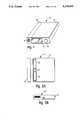
- FIG. 1is a perspective view of the ambulatory ECG monitor unit.
- FIG. 2Ais a top view of the ambulatory ECG monitor unit of FIG. 1.
- FIG. 2Bis a rear view of the ambulatory ECG monitor unit of FIG. 1.
- FIG. 3diagrammically illustrates typical electrode placements and the connection of the electrodes to the ambulatory ECG monitor unit.
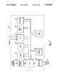
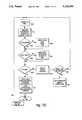
- FIG. 4is a block diagram depicting the major components of the ambulatory ECG monitor unit of FIG. 1.
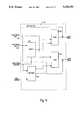
- FIG. 5is a more detailed block diagram illustrating the components of the analog circuitry shown in FIG. 4.
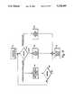
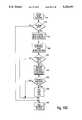
- FIG. 6is a more detailed block diagram illustrating the components of the pace pulse detector circuit of FIG. 4.
- FIG. 7is a more detailed block diagram illustrating, the components of the controller of FIG. 4.
- FIG. 8is a block diagram illustrating the inputs and outputs of the controller of FIG. 4.
- FIG. 9is a more detailed block diagram depicting the components of the data buffer of FIG. 4.
- FIG. 10diagrammically illustrates the connection of the ambulatory ECG monitor unit to a data processing system.
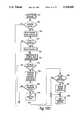
- FIG. 11is a flow chart of the basic operation of software for the CPU of FIG. 7.
- FIGS. 12A, 12B and 12Care flow charts depicting the steps of the Holter mode routine performed by the CPU of FIG. 7.
- FIG. 12Dis a flow chart of the interrupt routine performed by the CPU of FIG. 7 when in the Holter mode.
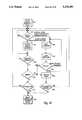
- FIGS. 13A, 13B and 13Care flow charts depicting the steps performed by the CPU of FIG. 7 when operating in high resolution mode.
- FIG. 13Dis a flow chart depicting the steps performed by the CPU of FIG. 7 when running an interrupt routine in high resolution mode.
- FIG. 14is a flow chart depicting the steps performed by the CPU of FIG. 7 when running the external connect routine.
- an ambulatory ECG systemincludes a monitor recording unit 10 such as shown in FIG. 1 for recording ECG data from a patient.
- the monitor unit 10is encased within a durable housing 12 made of plastic or other durable material which can withstand reasonable shock, temperatures and compression.
- the monitor unit 10is of an appropriate size and shape so that it may be readily carried by the patient.
- the illustrative embodiment of FIG. 1is polyhedral in shape and has dimensions of 1.3 inches in height, 3.6 inches in width and 5.1 inches in depth. The entire unit 10 only weighs 15 ounces. It should be appreciated that the shape, weight, and the dimensions shown in FIG. 1 are purely illustrative. Those skilled in the art will know of other suitable shapes and dimensions.
- monitor unit 10is of an appropriate size and shape so that it may be conveniently worn on a patient's belt with a suitable attachment such as a holster 11 shown in FIG. 3.
- a display 14for displaying status messages and the time of day.
- the display 14may be a conventional liquid crystal display (LCD).
- an event button 16located on the front face of the monitor unit 10 is an event button 16. This button allows the patient to record the time an event such as the suffering of chest pains occurred so that the ECG data recorded at that time can be flagged for closer examination.
- the front face of the monitor unit 10includes a seven pin connector 18 for connecting electrodes that gather ECG signals with the monitor unit 10.
- the monitor unit 10is powered by two conventional 9 volt radio batteries 22 and 24 which fit into the housing 12 underneath a sliding battery door 20. These batteries serve as a power supply to energize the monitor unit 10.
- the inventionis not limited to use of such 9 volt batteries; rather battery configurations, such as configurations employing AA batteries, may similarly be used. Batteries 22 and 24 are connected to the internal components of the unit via electrical connectors 26.
- the rear face of the monitor 10incorporates a pin connector 28 for connecting the monitor unit 10 to an external system such as a data processing system.
- an external systemsuch as a data processing system.
- This connectionallows data recorded by the monitor unit 10 to be retrieved by such an external system and facilitates communications between the external system and the monitor unit.
- Data retrieved via the connector 28may be processed by such an external system using well known algorithms for analyzing ECG data. Processing hardware, however, may also be directly incorporated within the monitor unit.
- the monitor unit 10is designed for use with a set of electrodes. In most applications, either two or three sets of electrodes are employed. For illustrative purposes, the discussion that follows will focus on the use of three sets of electrodes.
- three sets of electrodes 34a, 34b, 36a, 36b, 38a and 38bare employed to provide a three dimensional view of heart activity.
- the three pairs of electrodesprovide ECG signals from the X, Y and Z axes of the patient, respectively.
- the lead wire 33 for electrode 38bis shown in phantom because the electrode is placed on the patient's back (i.e., it is displaced relative to electrode 38a in the Z direction). This pattern of electrode placement corresponds to a standard established by the Association for the Advancement of Medical Instrumentation (AAMI).
- AAMIAssociation for the Advancement of Medical Instrumentation
- AAMIAssociation for the Advancement of Medical Instrumentation
- the electrodesmay be conventional are pre-gelled ECG silver chloride electrodes. These electrodes operate in pairs (i.e., 34a works as a pair with 34b, etc.) so that the three sets of electrodes 34a, 34b, 36 a, 36b, 38a and 38b provide three channels of analog ECG input. Each electrode is provided with a lead wire 33 that leads to the pin connector 18. As shown in FIG. 1, connector 18 has seven pins, that is one pin for each electrode.
- ECG signals retrieved from the electrodesare processed and stored by hardware located inside the monitor unit 10.
- This hardwareincludes a 21/2 inch disk drive 40 (see FIG. 4) such as a Prairie 242 disk drive sold by PrairieTek Corporation.
- the hardwareadditionally includes a printed circuit board containing components which will be described in more detail below.
- the disk drive 40 and the printed circuit boardare connected to the external pin connector 28 through a driver circuit 58.
- FIG. 4diagrammically illustrates the major components of the monitor unit 10 in block form.
- the monitor unit 10includes electrode connector 18 as previously described. This connector 18 is coupled to analog circuitry 46 that amplifies and processes the input ECG signals received through connector 18.
- the analog circuitry 46is connected to a controller 48 that controls the operation of the monitor and converts amplified analog ECG signals into digital form.
- the controller 48is connected to a power supply 54, which, as described above, may constitute two conventional 9 volt batteries 22 and 24 (see FIG. 2a).
- the controller 48is also coupled to the disk drive 40 which is used to store the digital ECG data.
- the disk drive 40like the controller 48, is powered by the power supply 54.
- the controller 48is coupled to a data buffer 56 which temporarily holds the digital ECG data before this data is written to disk by the disk drive 40.
- the internal components of the monitor unit 10also include an operator interface 50 which is connected to the display 14 and the event button 16. Still further, the monitor is provided with a real time clock 52.
- the real time clock 52has a non-volatile memory which is used to hold system status information. This memory is provided with its own battery to protect the data held therein in the event that main monitor power is interrupted.
- FIG. 5depicts the analog circuitry 46 of FIG. 4 in more detail.
- the analog circuitry 46contains separate sets of like circuitry 60 that operate on input from a respective pair of electrodes 34a, 34b, 36a, 36b, 38a and 38b. Hence, when three pairs of electrodes are used, the analog circuitry 46 includes three sets of circuitry 60.
- Each such set of circuitryincludes a differential amplifier circuit 62 employing amplifiers such as the Motorola MC34184D.
- the differential amplifier circuit 62receives the inputs from a respective pair of electrodes and generates an output corresponding to the difference between the levels of the two signals.
- each of the differential amplifier circuits 62is dictated by a respective set of control signals which are denoted as CTL1, CTL2 and CTL3 in FIG. 5. These control signals originate from a control unit 72 that receives gain and frequency information from the controller 48.
- control signalsoriginate from a control unit 72 that receives gain and frequency information from the controller 48.
- the use of such control signals and differential amplifier circuitsis well known in the prior art and will not be discussed in detail herein.
- each differential amplifier circuit 62passes to a conventional common mode and base line recovery circuit 64. Suitable amplifiers for this circuit include Motorola MC34184D amplifiers.
- the output from each common mode and base line recovery circuit 64passes to output circuitry 66.
- the output circuitry 66forwards the output (which constitutes a respective channel of data) to the controller 48. As seen in FIG. 5, a separate output circuit 66 provided for the channel 1, channel 2 and channel 3 outputs.
- Each common mode and base line recovery circuits 64also forwards the output to a pacemaker pulse detection circuit 70 which analyses the signal to determine if it includes a pacemaker pulse.
- the ability to identify the presence of a pacemaker pulse and the time it occursis greatly helpful to medical personnel who are examining a patient. In particular, it allows the determination of the time delay between a stimulus (i.e. a pacemaker pulse) and a heart beat. Further, such monitoring can help to determine whether a pacemaker is malfunctioning.
- FIG. 6depicts the pacemaker pulse detector circuit 70 in more detail.
- This circuitinterrupts the controller 48 with an output denoted as "Pacer" when a pacemaker pulse is detected.
- this circuit 70determines whether the amplitude of each of the received signals exceeds a given threshold level; hence indicating that the signal is likely a pacemaker pulse.
- the pacemaker pulse detector circuit 70includes a filter 74 for each input 68.
- the filters 74are bandpass filters that pass signals in the range of approximately 40 to 100 hertz. These filters may be implemented using amplifiers such as the Maxim ICL761DCSE and other conventional components. This filter eliminates those sections of the frequency range in which pacemaker pulses are not likely to be detected.
- the filtered outputsare then compared by a comparator circuit 78 that compares the filtered outputs with an amplitude threshold
- the thresholdis programmably selectable so that appropriate threshold may be selected for a particular patient.
- the circuitincludes a multiplexer 76 such as a Maxim DG212CSE which selects the filter output be compared by the comparator circuit 78. Due to the use of the multiplexer, one or more channels may be selectively monitored for the presence of such pacemaker pulses.
- the result of the comparison by the comparator circuit 78is passed to the controller as the "Pacer" signal.
- the "Pacer" signalinterrupts the controller 48 when a pace pulse is detected.
- FIG. 7diagrammically illustrates the components of the controller 48 in more detail.
- the controller 48is provided with two separate memories, an EPROM 84 and a RAM 86.
- the EPROM 84holds approximately 8 kilobytes of memory, whereas the RAM 86 holds 256 bytes of memory.
- the EPROM 84is used to store instructions to be executed by the CPU 90.
- the RAMis used as a buffer for incoming ECG data and for other special types of data including pacer and event data.
- the controller 48further includes a CPU 90 for controlling operation of the monitor unit 10.
- the CPU 90, the EPROM 84 and the RAM 86are all individually coupled to an internal bus 92 which facilitates communication between components connected thereto.
- the controller 48has an interrupt controller 82.
- the controllerincludes an oscillator 94 with an external crystal 93 which is connected to the CPU 90.
- the internal oscillatormay operate at 12 megahertz wherein each system clock cycle is comprised of twelve oscillator cycles (i.e., 1 microsecond).
- the controlleradditionally includes three counters 101 that are used for system timing.
- the third timeris a watchdog timer that is used to reset the microcontroller if the controller enters an erroneous processor state.
- a bus controller 96The bus controller 96 regulates access to the internal bus 92.
- An additional component connected to the internal bus 92is an analog to digital converter (ADC) 88.
- ADC 88produces 10 bit digital samples from the analog channels 1, 2 and 3.
- the ADC 88includes a buffer for temporarily holding the digital samples it produces. All 10 bits are used when the system is operating in a high resolution mode. The eight highest order bits are used when the system operates in a lower resolution mode. These two modes of operation will be discussed in more detail below.
- the internal busis also connected to input/output (I/0) ports 98 and a serial port 100.
- I/0input/output
- a suitable controller incorporating all of these componentsis the Signetics 87C552 sold by the Signetics Company. Nevertheless, other controllers can be used.
- FIG. 8illustrates the pin configuration of the controller 48.
- the controllerreceives analog ECG signals as input over channels 1, 2 and 3 from the analog circuitry through sets of pins 102, 104, 106. As mentioned previously, signals in these three channels are converted into digital samples by the internal ADC 88 of the controller 48 (see FIG. 7).
- the controller 48also receives, status information through pins 108 regarding the status of the batteries or power supply. If the batteries are too low, this status information is used to prompt a message on the LCD, warning the user of the drained batteries. Also, the controller 48 receives the "Pacer" interrupt through pin 110 when a pacemaker pulse is detected by the analog circuitry 46.
- the controller 48also has a number of pins used to carry output signals. In particular, it includes a serial port 112. Likewise, it has a number of address lines for sending addresses to the data buffer 56 (see FIG. 4). Furthermore, the controller includes a number of data pins 118 that may be used to transmit either data or addresses to the data buffer. As will be explained below in more detail, in the preferred embodiment, two RAMs 130 and 132 (see FIG. 9) are employed in the data buffer 56. As a result, when communicating with the data buffer 56, the controller 48 must indicate which RAM is selected. To accomplish such a selection, the controller has pins that are connected to RAM select lines. Only the selected RAM will be active at any time. Also provided at the controller 48 are read/write lines 124 which carry read or write pulses to the RAMs from the controller and a RAM refresh line 126 for refreshing the pseudo static RAMs of the data buffer.
- the controller 48further includes lines for carrying signals to the disk drive 40 (see FIG. 4).
- the controller 48has a number of output pins 120 that are used for carrying data to the disk drive 40. It is over these lines that the digital samples of ECG data are forwarded for storage in the buffer and on the disk. Further, a pin 122 is provided for connection to lines that carry read and write pulses to the disk drive.
- the data buffer 56is shown in more detail in FIG. 9. Specifically, the data buffer 56 includes two pseudo-static RAMs, 130 and 132. Suitable RAMs are Hitachi HM 658512 pseudo static RAMs. Other RAMs may, likewise, be used. Each of these RAMs holds 524,288 bytes of memory. In the present case, each of these RAMs are divided into three buffers: a data buffer, an event buffer and a pacer buffer. Separate read and write pointers are maintained for each of the three buffers.
- the data buffer 56also includes a demultiplexer 134 and a decoder 136.
- the function of the demultiplexer 134is best understood by looking at the data and address outputs of the data buffer 56. As shown in FIG. 9, the low order bits for an address to access either of the RAMs 130 or 132 come from pins 138 that are exclusively dedicated to transmitting address bits. However, the high order bits for an address to access either of the RAMs 130 or 132 are output from the controller on pins that can carry both addresses and data. As a result, it is necessary to differentiate whether data or an address is being transmitted over these pins when a transfer is made. The demultiplexer 134 latches the addresses into the RAMs as the higher order bits of the address when addresses are being transmitted to the RAMs.
- the demultiplexerdoes not latch the address into the RAMs. Instead, the data is passed to the data lines of the respective RAMs 130 and 132 so that the active. RAM receives the data.
- the select for the demultiplexer 134is the read/write signal for the RAMs which is issued by the controller. When the signal indicates a read, the demultiplexer 134 latches the address into the respective RAMs, whereas if the signal indicates a write, the data is forwarded to the data lines.
- the data buffer 56further includes a decoder 136 for decoding the control signals forwarded from the controller to the data buffer 56.
- decoder 136receives the RAM refresh signal from the controller as well as the read/write signal for the RAMs of the data buffer. It then generates appropriate signals to the respective RAMs.
- analog ECG signalsare acquired through the electrodes 34a, 34b, 36a, 36b, 38a and 38b.
- the analog ECG signalstravel over the lead wires 33 to the monitor unit 10 (see FIG. 3).
- This datapasses through the seven pin connector 18 to the analog circuitry 46 as shown in FIG. 4.
- the signals from the respective pairs of electrodesare processed in parallel by the circuitry 60 as shown in FIG. 5.
- the differential amplifiers 62amplify the input signals which are passed to the common mode and base line recovery circuits 64 in accordance with the gain and frequency response that is programmed by the controller.
- the ECG signalsare then forwarded to the output circuitry 66.
- the output circuitrypasses the signals onto the controller 48.
- the pacemaker pulse detector circuit 70examines the signals to determine whether their amplitude exceeds a given threshold, hence constituting a pacemaker pulse. Specifically, as depicted in FIG. 6, selected channel outputs pass through the bandpass filter 74 to the multiplexer 76, which selects the outputs for comparison by the comparator circuit 78. The selected output is compared by the comparator circuit 78, and the results of the comparison are passed to a buffer 80. If a pacemaker pulse is detected an interrupt is forwarded to the controller 48 (FIG. 4).
- the ECG signals from the three channelspass from the analog circuitry 46 (see FIG. 4) to the controller 48.
- the signalspass to ADC 88.
- ADC 88converts the signals into ten bit digital samples.
- the sampling rate of ADC 88is controlled by the CPU 90 of the controller 48 as will be explained in more detail below.
- the CPU 90forwards the digitized data to the data buffer 56 over the RAM data/address line 118 (see FIG. 8), and the data is written into one of the RAMs 130, 132 in the data buffer 56.
- the CPU 90 of the controller 48reads out the entire contents of the respective RAM 130, 132 and forwards the contents to the disk drive 40 (see FIG. 4) wherein the data is written onto disk.
- the disk drive 40is active only when a RAM is nearly full This approach conserves power by only operating the disk drive when necessary.
- the use of the buffer RAMsallows the disk drive only to be active for short intervals. Generally, the disk is active for twenty seconds for every eighty minutes of monitoring. Furthermore, since the disk can store approximately 42 megabytes of data, it has sufficient memory capacity to store all of the data received over the twenty four hour monitoring period without the need for data compression.
- the CPU 90(see FIG. 6) is programmed such that it will only operate for twenty four hours. Once twenty four hours have elapsed, the system idles and does not accept any more ECG signals from the patient.
- the data on the disk of the disk drive 40(see FIG. 4) is downloaded to a computer system such as shown in FIG. 10. If the analysis processing hardware is included in the monitor unit 10, however, such downloading is not necessary.
- a cable 136is connected to the external connector 28 and a data processing system 134. This allows the transmission of data between the monitor unit 10 and the data processing system 134.
- a dedicated data busconnects the disk drive 40 to the external connector 28. This data bus is within the driver circuitry 58 connecting the disk drive 40 with the connector 28 and allows the data processing system 134 to gain direct access to the data on the disk drive 40.
- the controlleris not involved in the data transfer. Rather, the disk drive 40 is isolated from the controller.
- the data processing system 134may treat the disk drive 40 as if it were a typical peripheral device connected to the data processing system.
- a typical data processing system 134such as a personal computer need not be used to download the data. Rather, a special module for interfacing with the external connector 28 may be provided to extract the data from the monitor unit 10.
- the monitoring unitWhen the monitoring unit is recording data, it can be operated in either a high resolution mode or a low resolution mode.
- the unit 10takes samples at a rate of 1,000 samples per second, thereby recording the ECG signals over a wide frequency band. As mentioned above, in this mode all ten bits of the samples are stored.
- the low resolution modeonly 200 samples per second are taken. In this mode, only eight bits of the samples are stored. This rate of sampling in the low resolution mode is still higher than conventional systems and, thus, is better able to detect late potentials.
- the monitor unit 10is also better able to detect late potentials because of its large dynamic range, which is on the order of 40 to 60 decibels.
- the CPU 90(see FIG. 7) of the controller 48 is programmed such that it initially operates in a mode specified by the non volatile memory of the clock 52. This memory holds status information that is used to recover the state of the monitor, should the monitor lose power or otherwise stop operating.
- the modesinclude the high resolution mode.
- the CPU 90may be toggled into the high resolution mode in two ways. First, the software for the CPU 90 may be programmed such that when the event button 16 (see FIG. 1) is pushed, the CPU shifts the unit 10 to high resolution mode for a predetermined time period. Second, the CPU may be programmed so that at predetermined intervals it automatically enters the high resolution mode.
- the high resolution modeis generally active for a short duration, such as ten minutes.
- the duration that the system is active in the high resolution modeis programmable. Further, the system may be programmed such that when this high resolution mode is completed, the monitor unit 10 switches back to the low resolution mode. In general, when the high resolution mode is completed, the system returns to an initial state wherein it looks to the non volatile memory of the clock to determine its current mode of operation.
- FIG. 11shows a flow chart of the basic steps performed by the CPU 90 when the monitor is powered up.
- the CPU 90executes an initialization routine to prepare the monitor unit for operation (step 140). Part of the initialization routine is to examine the status information held in the non-volatile clock memory, including information regarding the current mode of operation.
- the CPUdetermines the current mode of operation of the system (step 142). If the system is operating in high resolution mode, the controller 48 runs a high resolution mode routine (step 143). Similarly, if the system is in Holter mode, the controller 48 runs a Holter mode routine (step 144). Lastly, the system may run an external connection routine that facilitate connection of the monitor unit to an external device.
- the CPUWhen running the external connection routine, the CPU communicates with the connected external system (step 146). In addition, the CPU checks for errors (step 148). If an error has not occurred during the communication with tho external system, the CPU returns to its initial state wherein it again determines its current mode of operation (step 142). However, if an error occurs, the CPU idles and prompts the display of an error message (step 150). The CPU also idles and displays a final status message upon completion of the Holter mode or the high resolution mode.
- FIGS. 12A-12Dare flow charts of the steps performed when the unit is operating in the Holter mode.
- the CPUinitially sets system variables including status flags in the non-volatile memory so that the variables are proper for operation in the Holter mode (step 152). It then initiates the interrupt routine shown in FIG. 12D but does not begin data acquisition (step 154). Next, a short test sequence is initiated and the status is displayed on the display 14 (step 156). The system subsequently checks to see whether all tests have been passed (step 158), and if a test has failed, the error is displayed on the display 14 and the processor idles (step 160).
- step 162the system determines the time of day from clock 52 (see FIG. 4) and displays this time on the display 14 (step 164 in FIG. 12A).
- the CPU 90then enters power-down mode (step 166) and waits for an interrupt (see step 168).
- the CPU 90awakens and enters a process mode (step 170).
- the systemdetermines if the monitor unit 10 has completed data acquisition (step 172), (i.e., whether time has expired). If the system has reached completion, the CPU 90 updates the status on the display and acquires no more data (step 174).
- the systemthen idles until it is connected to an external device (step 178).
- the systemcontinuously tests for connection to an external device (step 180).
- the monitor unitruns the external interface routine (step 188).
- the unitUpon completion of the external interface routine, the unit returns to the power up initialization step of FIG. 11 (step 192).
- the systemdetermines whether the RAMs of the data buffer are full by checking whether a RAM FULL flag as been set (step 176). If the RAM FULL flag has not been set, the system determines whether an event/external connect flag has been set (step 182). If the event/external connect flag has not been set, the system determines whether the display should be updated (step 184). If it is not time to update the display, (i.e., does the time of the clock matches the displayed time), the system returns to the power down mode (step 166). In contrast, if the display requires updating, the system reads the updated time from the clock 52 (FIG. 4) and displays the updated time on the display (step 164, FIG. 12A).
- the CPU 90determines which of the two possible events that may set this flag has occurred. If the event button triggered setting of the flag, the event data held in the event buffer section of the internal RAM 86 (see FIG. 7) is updated (step 190, FIG. 12A). Specifically, when the event button is pushed, the system records the time from clock 52 and from counters 101 in the internal RAM that is eventually forwarded to an event buffer of the RAMs 130 and 132 of the data buffer as will be described below. Next, the above-described step of determining whether it is time to update the display (i.e., step 184) is performed. If, an external connection triggered the flag, the external interface routine is run (step 188).
- the RAM FULL flagindicates that the RAM is not full.
- the steps of FIG. 12Care performed.
- the disk driveis powered up (step 206). Powering up the disk drive only for short intervals, as mentioned above, helps to conserve power.
- the disk driveis fully powered up, the Holter ECG data is transferred from the RAM in the data buffer to the disk drive (step 204).
- the systemdetermines whether the transfer is a first transfer (step 202). In the case of a first transfer, the status information of the non-volatile memory of the clock is updated to reflect the start time of the transfer.
- the CPUdetermines whether event data is present in the event buffer portion of the RAM (step 200). If event data is present, the event data is written from the event data buffer portion of the RAM to the disk (step 210). The system then determines whether pacer data is present in the pacer buffer portion of the RAM (step 198). If pacer data is present, the pacer data is written from the appropriate portion of the RAM to the disk (step 212). In particular, when a pacer interrupt is sent, the system stores the time of the pacer interrupt. The pacer data referred to above is this time information. Subsequently, the system determines whether any errors have occurred (step 196). If an error has occurred, the error counter is updated (step 214).
- the systemdetermines whether a predetermined error limit has been exceeded (step 216). If the limit has not been exceeded, the system returns to transferring Holter data. If the error limit has been exceeded, the system halts operation and displays an error code (step 218). In the event that no errors have occurred, the system updates read and write pointers contained within the RAMs, clears the RAM FULL flag and, updates the disk read and write pointers (step 194). The system then returns to step 182 as depicted in FIG. 12B.
- the interrupt routine that is called in step 154 of FIG. 12A(ais depicted as a flow chart in FIG. 12D.
- the interrupt routineis run in the foreground of the CPU of the controller.
- the remaining time slots of the CPUare filled by the routines of FIGS. 12A-12C which may be said to run in the background of the CPU.
- the interrupt routineserves primarily to acquire new ECG data.
- the counters 101 in the controllersare initially updated (step 220). If the system is in a mode wherein it is not acquiring data, (see step 222) the system exits the interrupt routine (step 244). If the system, however, is in a mode where it is acquiring data, (see step 222) it reads the first and second channels of data from the buffer of the ADC (step 224). The system determines whether the third channel is enabled (step 226). The monitor unit 10 may be used with either two or set three sets of electrodes. If the third channel is not enabled (step 226), the system skips the third channel. If, in contrast, the third channel is enabled, the system reads the data in the third channel (step 228).
- the data read by the systemis stored in the internal RAM of the controller, and the external RAMs of the data buffer are refreshed via the refresh RAM signal sent from the controller (step 230).
- the systemnext determines whether the internal RAM is full (step 232). If the internal RAM is full, the data held in the internal RAM is transferred to the external RAMs of the data buffer (step 234).
- the systemsubsequently determines whether the external RAM of the data buffer is nearly full (step 236). If the external RAM is nearly full, the RAM FULL flag is set (step 238).
- the systemdetermines whether a pacemaker pulse has been detected by the pacemaker pulse detector circuit (step 240). If no pacemaker pulse has been detected, the system exits the interrupt routine. If a pacemaker pulse has been detected by the pacer detection circuit, pacemaker data held in the internal RAM is updated to include the time of the detected pulse (step 242). The controller then exits the interrupt routine (step 244).
- FIGS. 13A-13Dshow the steps performed by the system when operating in the high resolution mode.
- the controllerinitially sets system variables for operation in the high resolution mode (step 246).
- the systemthen starts an appropriate interrupt routine but does not yet begin data acquisition (step 248).
- the systemthen tests the functions of the monitor and posts the results of the tests on the display (step 250).
- the systemdetermines whether all tests have been passed (step 252) and idles if an error has occurred. When an error arises during the testing, the display exhibits an error message identifying the error (step 254). If all tests are passed, the system displays a ready code on the LCD (step 256).
- the systemdetermines whether the event button has been pressed (step 262).
- the systemdetermines whether a software programmable trigger time has been reached (step 266).
- the trigger timeis reached when a predetermined clock value is obtained. The system continues to check for these two events until one such event occurs. If the event button is pressed or if the trigger time is reached, the system enters a data acquisition mode (step 260). The system then reads and displays the time of day on the display (step 264).
- the controllernext enters a power down mode (step 268) wherein it checks continuously for an interrupt (step 270) that awakens it from the power down mode.
- an interruptoccurs, the system enters a process mode similar to operation in the Holter mode (step 272).
- the systemdetermines whether the system is done with the monitor procedure (step 274). If the system is done with the monitor procedure (i.e., no more data is to be acquired), it updates the system status on the display and stops acquiring data (step 278). The system then displays a ready code (step 256).
- step 276determines whether the RAM FULL flag has been set. If the RAM FULL flag has not been set, the system determines whether the event/external connect flag has been set (step 280). When the event/external connect flag has been set, the system determines whether an event or an external connection triggered the flag (step 284). If the event button triggered the flag, the information is updated in the event portion of the internal RAM (step 286). If an external connection triggered the flag, the external interface routine is run (step 288). Upon completion of the external interface routine, the system exits to the power up initialization sequence (step 290).
- step 280the system determines whether it is time to update the display (step 182). If it is not time to update the display, the system returns to the power-down mode (step 268). If it is time to update the display, the system reads and displays the updated time of day (step 264).
- step 276If the RAM FULL flag has been set (step 276), the steps shown in FIG. 13C are performed.
- the disk driveis powered-up (step 292), and ECG data then is transferred from the data buffer to the disk drive (step 294).
- the systemdetermines whether the transfer is the first data transfer (step 296). In the case of a first transfer, the non-volatile memory of the clock is updated to reflect the time of the first transfer.
- the systemalso determines whether there is an event data held in the RAM (step 300). If event data is present, the event data is written from the RAM buffer to the disk (step 302).
- the systemdetermines whether any errors have occurred (step 304). If an error does occur, the system updates the error counter (step 306). When the error limit is exceeded (step 308), monitor operation is halted and an error code is displayed (step 312). Upon completion of the data transfer, the read and write pointers for the RAMs are updated and the RAM FULL flag is cleared (step 310). Moreover, the read and write pointers for the disks are updated. The system then returns to check the event/external connect flag (step 280, FIG. 13B).
- FIG. 13Ddepicts the steps of the interrupt routine which is called in step 248 of FIG. 13A. Like the interrupt routine for the Holter mode, this routine runs in the foreground while the routine of FIGS. 13A-13C runs in the background. Initially in this routine, the timer registers are updated (step 314). The system then determines whether it is in a data acquisition mode (step 316). If the system is not in a data acquisition mode, it exits the interrupt routine (step 330). If the system is in a data acquisition mode, it reads the three channels of digitized ECG data (step 318, FIG. 13D) from the ADC buffers of the amplifier 46 (see FIG. 5). In this instance, the system does not determine whether the third channel is enabled because in the high resolution mode, all three channels are utilized. Then the system stores the data in the internal RAM of the controller and refreshes the external RAM of the data buffer (step 320).
- the systemdetermines whether the external RAM is near full (step 326). If the external RAM is near full, the RAM FULL flag is set (step 328). If the internal RAM is not full, as checked in step 322 or if the external RAM is not near full, as checked in step 326, or if the RAM full flag has been set, as in step 328, the system exits the interrupt routine (step 330).
- FIG. 14is a flow chart showing the steps of the external interface routine.
- the systemsets up the external interface state (step 332).
- the systemsubsequently determines its current mode of operation (step 334). If the system is in an idle mode, it continues to loop and determines its operating mode.
- the systemmay also operate in a mode where the external device communicates directly with the disk drive. When operating in such a mode, the system connects the disk drive to the external data bus (step 336).
- the external data busis exclusively dedicated for access by an external data processing system.
- the systemwaits until the transfer has been completed (see step 340). If an error occurred during the transfer (see step 344), the system processes the error (step 348).
- the systemdetermines whether the error is a recoverable error (step 352). If the error is a non-recoverable error, the system displays appropriate information indicating the error status (step 354). However, if the error is recoverable, the system continues in the external mode.
- the systemwaits until it is disconnected. Upon being disconnected, it displays the completion status on the display (step 354).
- the systemmay also operate in a mode where the external device communicates with the controller 48 (FIG. 4). When operating in this mode, the controller 48 reads a command (step 338) and sends a response (step 342). The CPU then checks the status of the system. If an error occurred, the system processes the error (step 348). If the CPU is done communicating with the external device, it, again, returns to step 334, wherein it checks the current mode of operation. Lastly, if the system is ready to accept a new command, it reads the next command (step 338) and again sends a response (step 342).
- the present inventionis not limited to ECG data.
- the monitor unitmay also be used to record other types of physiological data such as blood pressure.
Landscapes
- Health & Medical Sciences (AREA)
- Life Sciences & Earth Sciences (AREA)
- Heart & Thoracic Surgery (AREA)
- Surgery (AREA)
- Biophysics (AREA)
- Pathology (AREA)
- Engineering & Computer Science (AREA)
- Biomedical Technology (AREA)
- Veterinary Medicine (AREA)
- Medical Informatics (AREA)
- Molecular Biology (AREA)
- Physics & Mathematics (AREA)
- Animal Behavior & Ethology (AREA)
- General Health & Medical Sciences (AREA)
- Public Health (AREA)
- Cardiology (AREA)
- Measurement And Recording Of Electrical Phenomena And Electrical Characteristics Of The Living Body (AREA)
- Electrotherapy Devices (AREA)
- Measuring And Recording Apparatus For Diagnosis (AREA)
Abstract
Description
Claims (23)
Priority Applications (3)
| Application Number | Priority Date | Filing Date | Title |
|---|---|---|---|
| US07/695,600US5228450A (en) | 1991-05-03 | 1991-05-03 | Methods and apparatus for ambulatory physiological monitoring |
| EP92301543AEP0512667A1 (en) | 1991-05-03 | 1992-02-25 | Ambulatory electrocardiography monitor using disk storage |
| JP4112791AJPH05123303A (en) | 1991-05-03 | 1992-05-01 | Walkable physiological monitor |
Applications Claiming Priority (1)
| Application Number | Priority Date | Filing Date | Title |
|---|---|---|---|
| US07/695,600US5228450A (en) | 1991-05-03 | 1991-05-03 | Methods and apparatus for ambulatory physiological monitoring |
Publications (1)
| Publication Number | Publication Date |
|---|---|
| US5228450Atrue US5228450A (en) | 1993-07-20 |
Family
ID=24793686
Family Applications (1)
| Application Number | Title | Priority Date | Filing Date |
|---|---|---|---|
| US07/695,600Expired - Fee RelatedUS5228450A (en) | 1991-05-03 | 1991-05-03 | Methods and apparatus for ambulatory physiological monitoring |
Country Status (3)
| Country | Link |
|---|---|
| US (1) | US5228450A (en) |
| EP (1) | EP0512667A1 (en) |
| JP (1) | JPH05123303A (en) |
Cited By (96)
| Publication number | Priority date | Publication date | Assignee | Title |
|---|---|---|---|---|
| US5549115A (en)* | 1994-09-28 | 1996-08-27 | Heartstream, Inc. | Method and apparatus for gathering event data using a removable data storage medium and clock |
| US5645068A (en)* | 1995-03-20 | 1997-07-08 | Bioscan, Inc. | Methods and apparatus for ambulatory and non-ambulatory monitoring of physiological data using digital flash storage |
| US5678562A (en)* | 1995-11-09 | 1997-10-21 | Burdick, Inc. | Ambulatory physiological monitor with removable disk cartridge and wireless modem |
| US5701894A (en)* | 1995-11-09 | 1997-12-30 | Del Mar Avionics | Modular physiological computer-recorder |
| US5778882A (en)* | 1995-02-24 | 1998-07-14 | Brigham And Women's Hospital | Health monitoring system |
| US6014578A (en)* | 1998-08-06 | 2000-01-11 | Meotronic, Inc. | Ambulatory recorder having method of configuring size of data subject to loss in volatile memory |
| US6041257A (en)* | 1994-09-28 | 2000-03-21 | Heartstream | Method of using a measuring instrument and data gathering system |
| US6050940A (en)* | 1996-06-17 | 2000-04-18 | Cybernet Systems Corporation | General-purpose medical instrumentation |
| US6077223A (en)* | 1998-08-06 | 2000-06-20 | Medtronic, Inc. | Ambulatory recorder having control screen to present dual interface for dual users |
| US6115622A (en)* | 1998-08-06 | 2000-09-05 | Medtronic, Inc. | Ambulatory recorder having enhanced sampling technique |
| US6119029A (en)* | 1998-08-06 | 2000-09-12 | Medtronic, Inc. | Ambulatory recorder having splash resistant sensor ports |
| US6128520A (en)* | 1998-08-06 | 2000-10-03 | Medtronic, Inc. | Ambulatory recorder having volatile and non-volatile memories |
| US6141574A (en)* | 1998-08-06 | 2000-10-31 | Medtronic, Inc. | Ambulatory recorder having sliding period switches |
| US6142938A (en)* | 1998-08-06 | 2000-11-07 | Medtronic Inc. | Ambulatory data recorder having ergonomically shaped housing |
| US6154668A (en)* | 1998-08-06 | 2000-11-28 | Medtronics Inc. | Ambulatory recorder having a real time and non-real time processors |
| US6200264B1 (en) | 1998-08-06 | 2001-03-13 | Medtronic Inc. | Ambulatory recorder having wireless data transfer with a multi-plane lens |
| US6221012B1 (en)* | 1992-12-11 | 2001-04-24 | Siemens Medical Electronics, Inc. | Transportable modular patient monitor with data acquisition modules |
| US6245013B1 (en) | 1998-12-14 | 2001-06-12 | Medtronic, Inc. | Ambulatory recorder having synchronized communication between two processors |
| WO2001050433A1 (en)* | 1999-12-31 | 2001-07-12 | Ilife Systems, Inc. | Apparatus and method for reducing power consumption in physiological condition monitors |
| US20020143577A1 (en)* | 2001-04-02 | 2002-10-03 | Saul Shiffman | Apparatus and method for prediction and management of subject compliance in clinical research |
| US20020143563A1 (en)* | 2001-04-02 | 2002-10-03 | Hufford Michael R. | System for clinical trial subject compliance |
| US20020184369A1 (en)* | 2001-05-31 | 2002-12-05 | Parkinson Steven William | Appointment scheme for redistributing service access |
| US20040010425A1 (en)* | 2002-01-29 | 2004-01-15 | Wilkes Gordon J. | System and method for integrating clinical documentation with the point of care treatment of a patient |
| US20040015731A1 (en)* | 2002-07-16 | 2004-01-22 | International Business Machines Corporation | Intelligent data management fo hard disk drive |
| US20050004481A1 (en)* | 2003-07-01 | 2005-01-06 | Ge Medical Systems Information Technologies, Inc. | Method and apparatus for algorithm fusion of high-resolution electrocardiograms |
| US6968375B1 (en) | 1997-03-28 | 2005-11-22 | Health Hero Network, Inc. | Networked system for interactive communication and remote monitoring of individuals |
| US20060063993A1 (en)* | 2004-08-09 | 2006-03-23 | Dejin Yu | Method and apparatus for non-invasive measurement of blood analytes |
| US20060089541A1 (en)* | 1996-06-17 | 2006-04-27 | Braun Jeffrey C | General-purpose medical instrumentation |
| US7076435B1 (en)* | 1993-04-22 | 2006-07-11 | Datex-Ohmeda, Inc. | Method for transferring patient information from a source monitor to a destination monitor |
| US20060229522A1 (en)* | 2005-04-08 | 2006-10-12 | Exelys, Llc | Portable cardiac monitor including RF communication |
| US20060229521A1 (en)* | 2005-04-08 | 2006-10-12 | Exelys, Llc | Portable cardiac monitor |
| US20060229525A1 (en)* | 2005-04-08 | 2006-10-12 | Exelys, Llc | Portable cardiac monitor including pulsed power operation |
| US20060229523A1 (en)* | 2005-04-08 | 2006-10-12 | Exelys, Llc | Portable cardiac monitor including a range limiter |
| US20060235281A1 (en)* | 2005-04-15 | 2006-10-19 | Ivy Biomedical Systems, Inc. | Wireless patient monitoring system |
| US7167818B2 (en) | 1997-01-10 | 2007-01-23 | Health Hero Network, Inc. | Disease simulation system and method |
| US7223235B2 (en) | 1992-11-17 | 2007-05-29 | Health Hero Network, Inc. | System and method for monitoring blood pressure from a person |
| US7260480B1 (en) | 2003-04-07 | 2007-08-21 | Health Hero Network, Inc. | Method and system for integrating feedback loops in medical knowledge development and healthcare management |
| US20070225611A1 (en)* | 2006-02-06 | 2007-09-27 | Kumar Uday N | Non-invasive cardiac monitor and methods of using continuously recorded cardiac data |
| US7297109B2 (en) | 1992-11-17 | 2007-11-20 | Health Hero Network, Inc. | Method and system for improving adherence with a diet program or other medical regimen |
| US7305348B1 (en) | 1996-02-20 | 2007-12-04 | Health Hero Network, Inc. | Aggregating and pooling health related information in a communication system with feedback |
| US20080052259A1 (en)* | 2001-04-02 | 2008-02-28 | Saul Shiffman | Operation and method for prediction and management of the validity of subject reported data |
| EP1127537B1 (en)* | 2000-02-23 | 2008-07-02 | von Berg Medizingeräte GmbH | Portable recorder for recording and transmitting a multichannel ECG |
| US7399276B1 (en) | 2003-05-08 | 2008-07-15 | Health Hero Network, Inc. | Remote health monitoring system |
| US20090088654A1 (en)* | 2007-09-28 | 2009-04-02 | Siemens Aktiengesellschaft | EKG measurement device |
| US20090157127A1 (en)* | 2007-12-14 | 2009-06-18 | Cardiac Pacemakers, Inc. | Telemetry during safety mode operation |
| US7555436B2 (en) | 1997-01-16 | 2009-06-30 | Health Hero Network, Inc. | Personalized display of health information |
| US7584108B2 (en) | 1996-12-23 | 2009-09-01 | Health Hero Network, Inc. | Network media access control system for encouraging patient compliance with a treatment plan |
| US7613590B2 (en) | 1992-11-17 | 2009-11-03 | Health Hero Network, Inc. | Modular microprocessor-based power tool system |
| US7624028B1 (en) | 1992-11-17 | 2009-11-24 | Health Hero Network, Inc. | Remote health monitoring and maintenance system |
| US20090311970A1 (en)* | 2005-04-15 | 2009-12-17 | Ivy Biomedical Systems, Inc. | Wireless Transmitter |
| US7683958B1 (en)* | 2003-01-31 | 2010-03-23 | Foveon, Inc. | Camera exposure indication interface |
| US7689440B2 (en) | 1992-11-17 | 2010-03-30 | Health Hero Network, Inc. | Method and apparatus for remote health monitoring and providing health related information |
| US7765112B2 (en) | 1996-10-16 | 2010-07-27 | Health Hero Network, Inc. | Multiple patient monitoring system for proactive health management |
| US20100217143A1 (en)* | 2009-02-23 | 2010-08-26 | Hollis Whittington | Technique for determining signal quality in a physiologic sensing system using high frequency sampling |
| US7814143B2 (en) | 1997-03-10 | 2010-10-12 | Health Hero Network, Inc. | System and method for modifying documents sent over a communications network |
| US7862506B2 (en) | 1994-05-23 | 2011-01-04 | Health Hero Network, Inc. | Diabetes management system |
| US8005690B2 (en) | 1998-09-25 | 2011-08-23 | Health Hero Network, Inc. | Dynamic modeling and scoring risk assessment |
| US8027809B2 (en) | 1992-11-17 | 2011-09-27 | Health Hero Network, Inc. | Home power management system |
| US8078407B1 (en) | 1997-03-28 | 2011-12-13 | Health Hero Network, Inc. | System and method for identifying disease-influencing genes |
| US8078431B2 (en) | 1992-11-17 | 2011-12-13 | Health Hero Network, Inc. | Home power management system |
| US8095340B2 (en) | 1992-11-17 | 2012-01-10 | Health Hero Network, Inc. | Home power management system |
| US20120108911A1 (en)* | 2009-03-30 | 2012-05-03 | DanMedical Ltd. | Medical apparatus |
| US8234128B2 (en) | 2002-04-30 | 2012-07-31 | Baxter International, Inc. | System and method for verifying medical device operational parameters |
| US8380531B2 (en) | 2008-07-25 | 2013-02-19 | Invivodata, Inc. | Clinical trial endpoint development process |
| US8407063B2 (en) | 1992-11-17 | 2013-03-26 | Robert Bosch Healthcare Systems, Inc. | Multi-user remote health monitoring system with biometrics support |
| US8527206B2 (en) | 1999-03-22 | 2013-09-03 | Robert Bosch Gmbh | Research data collection and analysis |
| US8533029B2 (en) | 2001-04-02 | 2013-09-10 | Invivodata, Inc. | Clinical monitoring device with time shifting capability |
| US8538503B2 (en) | 2010-05-12 | 2013-09-17 | Irhythm Technologies, Inc. | Device features and design elements for long-term adhesion |
| US20130300575A1 (en)* | 2004-05-25 | 2013-11-14 | Medicomp, Inc. | Cooperative processing with mobile monitoring device and computer system |
| US8775196B2 (en) | 2002-01-29 | 2014-07-08 | Baxter International Inc. | System and method for notification and escalation of medical data |
| US9173670B2 (en) | 2013-04-08 | 2015-11-03 | Irhythm Technologies, Inc. | Skin abrader |
| US9597004B2 (en) | 2014-10-31 | 2017-03-21 | Irhythm Technologies, Inc. | Wearable monitor |
| US10016554B2 (en) | 2008-07-09 | 2018-07-10 | Baxter International Inc. | Dialysis system including wireless patient data |
| US10061899B2 (en) | 2008-07-09 | 2018-08-28 | Baxter International Inc. | Home therapy machine |
| US10173008B2 (en) | 2002-01-29 | 2019-01-08 | Baxter International Inc. | System and method for communicating with a dialysis machine through a network |
| US10271754B2 (en) | 2013-01-24 | 2019-04-30 | Irhythm Technologies, Inc. | Physiological monitoring device |
| US10276054B2 (en) | 2011-11-29 | 2019-04-30 | Eresearchtechnology, Inc. | Methods and systems for data analysis |
| US10278607B2 (en) | 2003-11-26 | 2019-05-07 | Braemar Manufacturing, Llc | System and method for processing and presenting arrhythmia information to facilitate heart arrhythmia identification and treatment |
| US10347374B2 (en) | 2008-10-13 | 2019-07-09 | Baxter Corporation Englewood | Medication preparation system |
| US10552577B2 (en) | 2012-08-31 | 2020-02-04 | Baxter Corporation Englewood | Medication requisition fulfillment system and method |
| US10646405B2 (en) | 2012-10-26 | 2020-05-12 | Baxter Corporation Englewood | Work station for medical dose preparation system |
| US10818387B2 (en) | 2014-12-05 | 2020-10-27 | Baxter Corporation Englewood | Dose preparation data analytics |
| US10971257B2 (en) | 2012-10-26 | 2021-04-06 | Baxter Corporation Englewood | Image acquisition for medical dose preparation system |
| US11083371B1 (en) | 2020-02-12 | 2021-08-10 | Irhythm Technologies, Inc. | Methods and systems for processing data via an executable file on a monitor to reduce the dimensionality of the data and encrypting the data being transmitted over the wireless network |
| US11107574B2 (en) | 2014-09-30 | 2021-08-31 | Baxter Corporation Englewood | Management of medication preparation with formulary management |
| US11246523B1 (en) | 2020-08-06 | 2022-02-15 | Irhythm Technologies, Inc. | Wearable device with conductive traces and insulator |
| US11350864B2 (en) | 2020-08-06 | 2022-06-07 | Irhythm Technologies, Inc. | Adhesive physiological monitoring device |
| US11367533B2 (en) | 2014-06-30 | 2022-06-21 | Baxter Corporation Englewood | Managed medical information exchange |
| US20220300434A1 (en)* | 2019-07-26 | 2022-09-22 | Boston Scientific Neuromodulation Corporation | Methods and systems for storage, retrieval, and visualization of signals and signal features |
| US11495334B2 (en) | 2015-06-25 | 2022-11-08 | Gambro Lundia Ab | Medical device system and method having a distributed database |
| US11516183B2 (en) | 2016-12-21 | 2022-11-29 | Gambro Lundia Ab | Medical device system including information technology infrastructure having secure cluster domain supporting external domain |
| US11575673B2 (en) | 2014-09-30 | 2023-02-07 | Baxter Corporation Englewood | Central user management in a distributed healthcare information management system |
| US11948112B2 (en) | 2015-03-03 | 2024-04-02 | Baxter Corporation Engelwood | Pharmacy workflow management with integrated alerts |
| USD1063079S1 (en) | 2021-08-06 | 2025-02-18 | Irhythm Technologies, Inc. | Physiological monitoring device |
| EP4419004A4 (en)* | 2021-10-20 | 2025-08-20 | Quoretech Llc | Portable egg device with online and offline modes and method for egg data analysis |
| US12412644B2 (en) | 2014-10-24 | 2025-09-09 | Baxter Corporation Englewood | Automated exchange of healthcare information for fulfillment of medication doses |
Families Citing this family (8)
| Publication number | Priority date | Publication date | Assignee | Title |
|---|---|---|---|---|
| DE4339188A1 (en)* | 1993-11-16 | 1995-05-18 | Mueller & Sebastiani Elek Gmbh | Portable device for recording body-specific measurement data |
| DE19609411C2 (en)* | 1996-03-04 | 1999-11-25 | Biotronik Mess & Therapieg | Method and device for storing signals in an implantable medical device |
| FR2757289B1 (en)* | 1996-12-17 | 1999-02-26 | Ela Medical Sa | METHOD FOR REMOTE ANALYSIS OF PHYSIOLOGICAL DATA COLLECTED BY AN AUTONOMOUS AMBULATORY APPARATUS OR AN IMPLANTED ACTIVE MEDICAL DEVICE |
| FR2842324B1 (en)* | 2002-07-12 | 2006-04-28 | Herve Michalski | DEVICE FOR COLLECTING IN THE MEDICAL DOMAIN INFORMATION ABOUT A PATIENT |
| BRPI0506434A (en)* | 2004-02-18 | 2006-12-26 | Jozsef Beres | apparatus and method for measuring hemodynamic parameters |
| JP4851847B2 (en)* | 2006-05-30 | 2012-01-11 | 株式会社東芝 | Biological information measuring device |
| JP5061011B2 (en)* | 2008-03-31 | 2012-10-31 | フクダ電子株式会社 | Pacemaker pulse detector |
| WO2024208541A1 (en)* | 2023-04-04 | 2024-10-10 | Biotronik Se & Co. Kg | Implantable medical device for sensing electrocardiogram signals |
Citations (23)
| Publication number | Priority date | Publication date | Assignee | Title |
|---|---|---|---|---|
| US2986606A (en)* | 1955-02-28 | 1961-05-30 | Cambridge Instr Co Inc | Recording with audible and visible monitoring |
| US3221334A (en)* | 1961-03-23 | 1965-11-30 | Navigation Computer Corp | Recording system |
| US3897774A (en)* | 1974-01-28 | 1975-08-05 | Baxter Laboratories Inc | Signal processing circuit |
| US3908640A (en)* | 1974-11-25 | 1975-09-30 | Robert E Page | Cardiovascular instrument |
| US4073011A (en)* | 1976-08-25 | 1978-02-07 | Del Mar Avionics | Electrocardiographic computer |
| US4106495A (en)* | 1977-04-11 | 1978-08-15 | Del Mar Avionics | Vectorcardiographic method for ambulatory patients |
| US4136690A (en)* | 1977-10-31 | 1979-01-30 | Del Mar Avionics | Method and apparatus for vector analysis of ECG arrhythmias |
| DE2816494A1 (en)* | 1978-04-15 | 1979-10-25 | Collectron System Ag | Physiological value detection instrument - has A=D converter and value memory unit of CMOS type |
| US4211238A (en)* | 1978-06-23 | 1980-07-08 | Del Mar Avionics | Apparatus and method for recording and playing back electrocardial signals |
| US4249538A (en)* | 1978-10-24 | 1981-02-10 | Toshimitsu Musha | Electronic clinic apparatus |
| US4250888A (en)* | 1977-12-14 | 1981-02-17 | Carl Zeiss-Stiftung | Heartbeat monitoring process and device |
| US4291703A (en)* | 1978-11-01 | 1981-09-29 | Del Mar Avionics | Pacemaker monitoring recorder |
| US4336810A (en)* | 1980-09-30 | 1982-06-29 | Del Mar Avionics | Method and apparatus for arrhythmia analysis of ECG recordings |
| US4400745A (en)* | 1980-11-17 | 1983-08-23 | Del Mar Avionics | Tape transport |
| US4483347A (en)* | 1982-03-10 | 1984-11-20 | Del Mar Avionics | Method and apparatus for displaying electrocardiographic signals |
| US4519398A (en)* | 1979-07-09 | 1985-05-28 | Del Mar Avionics | Method and apparatus for long-term monitoring of physiological activity to provide a compact portable record |
| US4528988A (en)* | 1982-03-10 | 1985-07-16 | Del Mar Avionics | Method and apparatus for displaying electrocardiographic signals |
| US4532934A (en)* | 1978-11-01 | 1985-08-06 | Del Mar Avionics | Pacemaker monitoring recorder and malfunction analyzer |
| US4773097A (en)* | 1984-05-31 | 1988-09-20 | Omron Tateisi Electronics Co. | Image analyzing apparatus |
| US4883065A (en)* | 1988-11-15 | 1989-11-28 | Del Mar Avionics | Micropotential analyzer--a Holter system with comprehensive analysis capability for very low amplitude electrocardiographic signals and method |
| US5058597A (en)* | 1989-04-27 | 1991-10-22 | Terumo Kabushiki Kaisha | Long-term electrocardiograph for screening |
| US5086778A (en)* | 1989-07-21 | 1992-02-11 | Mueller & Sebastiani Elektronik Gmbh | Method and system for evaluating data picked-up by means of long term ecg devices |
| US5092341A (en)* | 1990-06-18 | 1992-03-03 | Del Mar Avionics | Surface ecg frequency analysis system and method based upon spectral turbulence estimation |
- 1991
- 1991-05-03USUS07/695,600patent/US5228450A/ennot_activeExpired - Fee Related
- 1992
- 1992-02-25EPEP92301543Apatent/EP0512667A1/ennot_activeWithdrawn
- 1992-05-01JPJP4112791Apatent/JPH05123303A/enactivePending
Patent Citations (25)
| Publication number | Priority date | Publication date | Assignee | Title |
|---|---|---|---|---|
| US2986606A (en)* | 1955-02-28 | 1961-05-30 | Cambridge Instr Co Inc | Recording with audible and visible monitoring |
| US3221334A (en)* | 1961-03-23 | 1965-11-30 | Navigation Computer Corp | Recording system |
| US3897774A (en)* | 1974-01-28 | 1975-08-05 | Baxter Laboratories Inc | Signal processing circuit |
| US3908640A (en)* | 1974-11-25 | 1975-09-30 | Robert E Page | Cardiovascular instrument |
| US4073011A (en)* | 1976-08-25 | 1978-02-07 | Del Mar Avionics | Electrocardiographic computer |
| US4123785A (en)* | 1976-08-25 | 1978-10-31 | Del Mar Avionics | Recorder for cardiac signals with manually actuated event marking |
| USRE29921E (en)* | 1976-08-25 | 1979-02-27 | Del Mar Avionics | Electrocardiographic computer |
| US4106495A (en)* | 1977-04-11 | 1978-08-15 | Del Mar Avionics | Vectorcardiographic method for ambulatory patients |
| US4136690A (en)* | 1977-10-31 | 1979-01-30 | Del Mar Avionics | Method and apparatus for vector analysis of ECG arrhythmias |
| US4250888A (en)* | 1977-12-14 | 1981-02-17 | Carl Zeiss-Stiftung | Heartbeat monitoring process and device |
| DE2816494A1 (en)* | 1978-04-15 | 1979-10-25 | Collectron System Ag | Physiological value detection instrument - has A=D converter and value memory unit of CMOS type |
| US4211238A (en)* | 1978-06-23 | 1980-07-08 | Del Mar Avionics | Apparatus and method for recording and playing back electrocardial signals |
| US4249538A (en)* | 1978-10-24 | 1981-02-10 | Toshimitsu Musha | Electronic clinic apparatus |
| US4532934A (en)* | 1978-11-01 | 1985-08-06 | Del Mar Avionics | Pacemaker monitoring recorder and malfunction analyzer |
| US4291703A (en)* | 1978-11-01 | 1981-09-29 | Del Mar Avionics | Pacemaker monitoring recorder |
| US4519398A (en)* | 1979-07-09 | 1985-05-28 | Del Mar Avionics | Method and apparatus for long-term monitoring of physiological activity to provide a compact portable record |
| US4336810A (en)* | 1980-09-30 | 1982-06-29 | Del Mar Avionics | Method and apparatus for arrhythmia analysis of ECG recordings |
| US4400745A (en)* | 1980-11-17 | 1983-08-23 | Del Mar Avionics | Tape transport |
| US4483347A (en)* | 1982-03-10 | 1984-11-20 | Del Mar Avionics | Method and apparatus for displaying electrocardiographic signals |
| US4528988A (en)* | 1982-03-10 | 1985-07-16 | Del Mar Avionics | Method and apparatus for displaying electrocardiographic signals |
| US4773097A (en)* | 1984-05-31 | 1988-09-20 | Omron Tateisi Electronics Co. | Image analyzing apparatus |
| US4883065A (en)* | 1988-11-15 | 1989-11-28 | Del Mar Avionics | Micropotential analyzer--a Holter system with comprehensive analysis capability for very low amplitude electrocardiographic signals and method |
| US5058597A (en)* | 1989-04-27 | 1991-10-22 | Terumo Kabushiki Kaisha | Long-term electrocardiograph for screening |
| US5086778A (en)* | 1989-07-21 | 1992-02-11 | Mueller & Sebastiani Elektronik Gmbh | Method and system for evaluating data picked-up by means of long term ecg devices |
| US5092341A (en)* | 1990-06-18 | 1992-03-03 | Del Mar Avionics | Surface ecg frequency analysis system and method based upon spectral turbulence estimation |
Non-Patent Citations (18)
| Title |
|---|
| Berbari et al., "An Introduction to High Resolution ECG Recordings of Cardiac Late Potentials", Arch. Intern. Med., vol. 148, (Sug. 1988) 1859-1863. |
| Berbari et al., An Introduction to High Resolution ECG Recordings of Cardiac Late Potentials , Arch. Intern. Med., vol. 148, (Sug. 1988) 1859 1863.* |
| IBM Tech. Discl. Bull., vol. 26, No. 11, Apr. 1984, pp. 6013 6015.* |
| IBM Tech. Discl. Bull., vol. 26, No. 11, Apr. 1984, pp. 6013-6015. |
| Kauffmann et al., "A Study of Non-Stationary Phenomena of HRV During 24-Hour ECG Ambulatory Monitoring", Proc. IEEE Conf. of Computers and Cardiology, (1989) 303-306. |
| Kauffmann et al., A Study of Non Stationary Phenomena of HRV During 24 Hour ECG Ambulatory Monitoring , Proc. IEEE Conf. of Computers and Cardiology , (1989) 303 306.* |
| Lamberti et al., "ECG Data Compression for Ambulatory Device", Proc. of IEEE Conf. on Computers and Cardiology, (1989), 171-174. |
| Lamberti et al., ECG Data Compression for Ambulatory Device , Proc. of IEEE Conf. on Computers and Cardiology, (1989), 171 174.* |
| Loring et al., "Out-patient 24-hour Holter Monitoring: Clinical, Technical and Economic Considerations" J. of Ambulatory Monitoring, vol. 1, No. 1 (1988) 7-16. |
| Loring et al., Out patient 24 hour Holter Monitoring: Clinical, Technical and Economic Considerations J. of Ambulatory Monitoring , vol. 1, No. 1 (1988) 7 16.* |
| Narramore et al., "Optimising Solid State Holter Systems", Proc. of IEEE Conf. on Computers & Cardiology, (1989), 575-578. |
| Narramore et al., Optimising Solid State Holter Systems , Proc. of IEEE Conf. on Computers & Cardiology, (1989), 575 578.* |
| Shah et al., "MEDICOMPACT: An ECG Data Compactor," Proc. of IEEE Conf. on Computers and Cardiology, (1989) 573. |
| Shah et al., MEDICOMPACT: An ECG Data Compactor, Proc. of IEEE Conf. on Computers and Cardiology, (1989) 573.* |
| Sheffield et al., "Recommendations for Standards of Instrumentation and Practice in the Use of Ambulatory Electrocardiography", Circulation, vol. 71, No. 3, Mar. 1985. |
| Sheffield et al., Recommendations for Standards of Instrumentation and Practice in the Use of Ambulatory Electrocardiography , Circulation , vol. 71, No. 3, Mar. 1985.* |
| Smith et al., "An ECG Compression Algorithm For Full Disclosure in a Solid State Real-Time Holter Monitor", Proc. of IEEE Conf. on Computers and Cardiology, (1989) 569-572. |
| Smith et al., An ECG Compression Algorithm For Full Disclosure in a Solid State Real Time Holter Monitor , Proc. of IEEE Conf. on Computers and Cardiology, (1989) 569 572.* |
Cited By (264)
| Publication number | Priority date | Publication date | Assignee | Title |
|---|---|---|---|---|
| US7941327B2 (en) | 1992-11-17 | 2011-05-10 | Health Hero Network, Inc. | User monitoring |
| US7223236B2 (en) | 1992-11-17 | 2007-05-29 | Health Hero Network, Inc. | System and method for monitoring user-related data from a person |
| US7624028B1 (en) | 1992-11-17 | 2009-11-24 | Health Hero Network, Inc. | Remote health monitoring and maintenance system |
| US7613590B2 (en) | 1992-11-17 | 2009-11-03 | Health Hero Network, Inc. | Modular microprocessor-based power tool system |
| US7827040B2 (en) | 1992-11-17 | 2010-11-02 | Health Hero Network, Inc. | Patient control of health-related data in a remote patient monitoring system |
| US7853455B2 (en) | 1992-11-17 | 2010-12-14 | Health Hero Network, Inc. | Remote health monitoring and maintenance system |
| US8027809B2 (en) | 1992-11-17 | 2011-09-27 | Health Hero Network, Inc. | Home power management system |
| US7877276B2 (en) | 1992-11-17 | 2011-01-25 | Health Hero Network, Inc. | Messaging to remote patients in a networked health-monitoring system |
| US7297109B2 (en) | 1992-11-17 | 2007-11-20 | Health Hero Network, Inc. | Method and system for improving adherence with a diet program or other medical regimen |
| US7941323B2 (en) | 1992-11-17 | 2011-05-10 | Health Hero Network, Inc. | Remote health monitoring and maintenance system |
| US8078431B2 (en) | 1992-11-17 | 2011-12-13 | Health Hero Network, Inc. | Home power management system |
| US8024201B2 (en) | 1992-11-17 | 2011-09-20 | Health Hero Network, Inc. | Method and apparatus for remote health monitoring and providing health related information |
| US7264591B2 (en) | 1992-11-17 | 2007-09-04 | Health Hero Netowrk, Inc. | System and method for monitoring air flow from a person |
| US9477939B2 (en) | 1992-11-17 | 2016-10-25 | Robert Bosch Healthcare Systems, Inc. | Radio frequency based remote health monitoring |
| US8095340B2 (en) | 1992-11-17 | 2012-01-10 | Health Hero Network, Inc. | Home power management system |
| US8249894B2 (en) | 1992-11-17 | 2012-08-21 | Robert Bosch Healthcare, Inc. | Networked remote patient monitoring with handheld devices |
| US7223235B2 (en) | 1992-11-17 | 2007-05-29 | Health Hero Network, Inc. | System and method for monitoring blood pressure from a person |
| US9215979B2 (en) | 1992-11-17 | 2015-12-22 | Robert Bosch Healthcare Systems, Inc. | Multi-user remote health monitoring system |
| US7761312B2 (en) | 1992-11-17 | 2010-07-20 | Health Hero Network, Inc. | Remote health monitoring and maintenance system |
| US8019618B2 (en) | 1992-11-17 | 2011-09-13 | Health Hero Network, Inc. | Report generation in a networked health-monitoring system |
| US7877274B2 (en) | 1992-11-17 | 2011-01-25 | Health Hero Network, Inc. | Messaging to remote patients in a networked health-monitoring system |
| US8617065B2 (en) | 1992-11-17 | 2013-12-31 | Robert Bosch Healthcare Systems, Inc. | Networked system for interactive communication and remote monitoring of individuals |
| US7689440B2 (en) | 1992-11-17 | 2010-03-30 | Health Hero Network, Inc. | Method and apparatus for remote health monitoring and providing health related information |
| US8015025B2 (en) | 1992-11-17 | 2011-09-06 | Health Hero Network, Inc. | Method and apparatus for remote health monitoring and providing health related information |
| US8489428B2 (en) | 1992-11-17 | 2013-07-16 | Robert Bosch Healthcare Systems, Inc. | Remote health monitoring and maintenance system |
| US8419636B2 (en) | 1992-11-17 | 2013-04-16 | Robert Bosch Healthcare Systems, Inc. | Method and system for improving adherence with a diet program or other medical regimen |
| US8015030B2 (en) | 1992-11-17 | 2011-09-06 | Health Hero Network, Inc. | User-based health monitoring |
| US8407063B2 (en) | 1992-11-17 | 2013-03-26 | Robert Bosch Healthcare Systems, Inc. | Multi-user remote health monitoring system with biometrics support |
| US8260630B2 (en) | 1992-11-17 | 2012-09-04 | Health Hero Network, Inc. | Modular microprocessor-based appliance system |
| US7979284B2 (en) | 1992-11-17 | 2011-07-12 | Health Hero Network, Inc. | Interactive video based remote health monitoring system |
| US6221012B1 (en)* | 1992-12-11 | 2001-04-24 | Siemens Medical Electronics, Inc. | Transportable modular patient monitor with data acquisition modules |
| US7076435B1 (en)* | 1993-04-22 | 2006-07-11 | Datex-Ohmeda, Inc. | Method for transferring patient information from a source monitor to a destination monitor |
| US7901625B2 (en) | 1994-04-26 | 2011-03-08 | Health Hero Network, Inc. | System for performing diabetes self-care |
| US7966230B2 (en) | 1994-04-26 | 2011-06-21 | Health Hero Network, Inc. | Method and apparatus for remote health monitoring and providing health related information |
| US9123083B2 (en) | 1994-04-26 | 2015-09-01 | Robert Bosch Healthcare Systems, Inc. | Blood glucose monitoring system |
| US7908152B2 (en) | 1994-04-26 | 2011-03-15 | Health Hero Network, Inc. | Blood glucose monitoring system |
| US7904310B2 (en) | 1994-04-26 | 2011-03-08 | Health Hero Network, Inc. | Blood glucose monitoring system |
| US7877271B2 (en) | 1994-04-26 | 2011-01-25 | Health Hero Network, Inc. | Blood glucose monitoring system |
| US8616895B2 (en) | 1994-05-23 | 2013-12-31 | Robert Bosch Healthcare Systems, Inc. | System and method for monitoring a physiological condition |
| US8655259B2 (en) | 1994-05-23 | 2014-02-18 | Robert Bosch Healthcare Systems, Inc. | System and method for monitoring a physiological condition |
| US7972267B2 (en) | 1994-05-23 | 2011-07-05 | Health Hero Network, Inc. | Diabetes management system |
| US7871376B2 (en) | 1994-05-23 | 2011-01-18 | Health Hero Network, Inc. | System and method for monitoring a physiological condition |
| US7862506B2 (en) | 1994-05-23 | 2011-01-04 | Health Hero Network, Inc. | Diabetes management system |
| US7867165B2 (en) | 1994-05-23 | 2011-01-11 | Health Hero Network, Inc. | System and method for monitoring a physiological condition |
| US7869852B2 (en) | 1994-05-23 | 2011-01-11 | Health Hero Network, Inc. | Diabetes management system |
| US5680864A (en)* | 1994-09-28 | 1997-10-28 | Heartstream, Inc. | Method for processing event data using a removable data storage medium and clock |
| US5749913A (en)* | 1994-09-28 | 1998-05-12 | Heartstream, Inc. | System and method for collecting and storing electrotherapy data on a detachable memory device |
| US5549115A (en)* | 1994-09-28 | 1996-08-27 | Heartstream, Inc. | Method and apparatus for gathering event data using a removable data storage medium and clock |
| US5785043A (en)* | 1994-09-28 | 1998-07-28 | Heartstream, Inc. | Method of creating a report showing the time correlation between recorded medical events |
| US5674252A (en)* | 1994-09-28 | 1997-10-07 | Heartstream, Inc. | Quality assurance method for a care delivery system |
| US5891046A (en)* | 1994-09-28 | 1999-04-06 | Heartstream, Inc. | Method of assembling a time-correlated medical event database |
| US6041257A (en)* | 1994-09-28 | 2000-03-21 | Heartstream | Method of using a measuring instrument and data gathering system |
| US5891049A (en)* | 1994-09-28 | 1999-04-06 | Heartstream, Inc | Time and data correlated medical display system |
| US5899866A (en)* | 1994-09-28 | 1999-05-04 | Heartstream, Inc. | Method and apparatus for recording and replaying time-correlated medical event data |
| US5951485A (en)* | 1994-09-28 | 1999-09-14 | Heartstream, Inc. | Method and apparatus for recording and replaying time-correlated medical event data |
| US6047207A (en)* | 1994-09-28 | 2000-04-04 | Heartstream, Inc. | Method of using a measuring instrument and data gathering system |
| US6095985A (en)* | 1995-02-24 | 2000-08-01 | Brigham And Women's Hospital | Health monitoring system |
| US6440069B1 (en) | 1995-02-24 | 2002-08-27 | Brigham & Women's Hospital | Health monitoring system |
| US7273454B2 (en) | 1995-02-24 | 2007-09-25 | Brigham And Women's Hospital | Health monitoring system |
| US20040087839A1 (en)* | 1995-02-24 | 2004-05-06 | Brigham And Women's Hospital | Health monitoring system |
| US6282441B1 (en) | 1995-02-24 | 2001-08-28 | Brigham & Women's Hospital | Health monitoring system |
| US6640134B2 (en) | 1995-02-24 | 2003-10-28 | Brigham And Women's Hospital | Health monitoring system |
| US5778882A (en)* | 1995-02-24 | 1998-07-14 | Brigham And Women's Hospital | Health monitoring system |
| US5645068A (en)* | 1995-03-20 | 1997-07-08 | Bioscan, Inc. | Methods and apparatus for ambulatory and non-ambulatory monitoring of physiological data using digital flash storage |
| US7258666B2 (en) | 1995-06-07 | 2007-08-21 | Health Hero Network, Inc. | System and methods for monitoring a patient's heart condition |
| US7684999B2 (en) | 1995-06-07 | 2010-03-23 | Health Hero Network, Inc. | User-based health monitoring |
| US5678562A (en)* | 1995-11-09 | 1997-10-21 | Burdick, Inc. | Ambulatory physiological monitor with removable disk cartridge and wireless modem |
| US5701894A (en)* | 1995-11-09 | 1997-12-30 | Del Mar Avionics | Modular physiological computer-recorder |
| US7305348B1 (en) | 1996-02-20 | 2007-12-04 | Health Hero Network, Inc. | Aggregating and pooling health related information in a communication system with feedback |
| US6050940A (en)* | 1996-06-17 | 2000-04-18 | Cybernet Systems Corporation | General-purpose medical instrumentation |
| US20020151771A1 (en)* | 1996-06-17 | 2002-10-17 | Braun Jeffrey C. | General-purpose medical instrumentation |
| US6375614B1 (en) | 1996-06-17 | 2002-04-23 | Cybernet Systems Corporation | General-purpose medical istrumentation |
| US20060089541A1 (en)* | 1996-06-17 | 2006-04-27 | Braun Jeffrey C | General-purpose medical instrumentation |
| US6875174B2 (en) | 1996-06-17 | 2005-04-05 | Cybernet Systems Corporation | General-purpose medical instrumentation |
| US8079953B2 (en) | 1996-06-17 | 2011-12-20 | Cybernet Systems Corporation | General-purpose medical instrumentation |
| US8562527B2 (en) | 1996-06-17 | 2013-10-22 | Cybernet Systems Corporation | General-purpose medical instrumentation |
| US7769605B2 (en) | 1996-10-16 | 2010-08-03 | Health Hero Network, Inc. | Multiple patient monitoring system for proactive health management |
| US7765112B2 (en) | 1996-10-16 | 2010-07-27 | Health Hero Network, Inc. | Multiple patient monitoring system for proactive health management |
| US7840420B2 (en) | 1996-10-16 | 2010-11-23 | Health Hero Network, Inc. | Multiple patient monitoring system for proactive health management |
| US7778845B2 (en) | 1996-10-16 | 2010-08-17 | Health Hero Network, Inc. | Multiple patient monitoring system for proactive health management |
| US7590549B2 (en) | 1996-12-23 | 2009-09-15 | Health Hero Network, Inc. | Network media access control system for encouraging patient compliance with a treatment plan |
| US7584108B2 (en) | 1996-12-23 | 2009-09-01 | Health Hero Network, Inc. | Network media access control system for encouraging patient compliance with a treatment plan |
| US7636667B2 (en) | 1996-12-23 | 2009-12-22 | Health Hero Networks, Inc. | Network media access control system for encouraging patient compliance with a treatment plan |
| US7643971B2 (en) | 1997-01-10 | 2010-01-05 | Health Hero Network, Inc. | Disease simulation system and method |
| US7167818B2 (en) | 1997-01-10 | 2007-01-23 | Health Hero Network, Inc. | Disease simulation system and method |
| USRE43316E1 (en) | 1997-01-10 | 2012-04-17 | Health Hero Network, Inc. | Diabetes management system and method for controlling blood glucose |
| US7392167B2 (en) | 1997-01-10 | 2008-06-24 | Health Hero Network, Inc. | Disease simulation system and method |
| US7925522B2 (en) | 1997-01-16 | 2011-04-12 | Health Hero Network, Inc. | Personalized body image |
| US7613621B2 (en) | 1997-01-16 | 2009-11-03 | Health Hero Network, Inc. | Personalized body image |
| US7555436B2 (en) | 1997-01-16 | 2009-06-30 | Health Hero Network, Inc. | Personalized display of health information |
| US7814143B2 (en) | 1997-03-10 | 2010-10-12 | Health Hero Network, Inc. | System and method for modifying documents sent over a communications network |
| US7310668B2 (en) | 1997-03-28 | 2007-12-18 | Health Hero Network, Inc. | Remotely monitoring an individual using scripted communications |
| US7516192B2 (en) | 1997-03-28 | 2009-04-07 | Health Hero Network, Inc. | Networked system for interactive communication and remote monitoring of individuals |
| US7730177B2 (en) | 1997-03-28 | 2010-06-01 | Health Hero Network, Inc. | Networked system for interactive communication and remote monitoring of individuals |
| US7734718B2 (en) | 1997-03-28 | 2010-06-08 | Health Hero Network, Inc. | Smart appliance functionality |
| US8353827B2 (en) | 1997-03-28 | 2013-01-15 | Robert Bosch Healthcare Systems, Inc. | Networked system for interactive communication and remote monitoring of individuals |
| US8608653B2 (en) | 1997-03-28 | 2013-12-17 | Robert Bosch Gmbh | Networked system for interactive communication and remote monitoring of individuals |
| US7587469B2 (en) | 1997-03-28 | 2009-09-08 | Health Hero Network, Inc. | Audio instructions for appliances |
| US7252636B2 (en) | 1997-03-28 | 2007-08-07 | Health Hero Network, Inc. | Networked system for interactive communication and remote monitoring of individuals |
| US7921186B2 (en) | 1997-03-28 | 2011-04-05 | Health Hero Network, Inc. | Networked system for interactive communication and remote monitoring of individuals |
| US7533171B2 (en) | 1997-03-28 | 2009-05-12 | Health Hero Network, Inc. | Networked system for interactive communication and remote monitoring of individuals |
| US7822625B2 (en) | 1997-03-28 | 2010-10-26 | Health Hero Network, Inc. | Networked system for interactive communication and remote monitoring of individuals |
| US8990336B2 (en) | 1997-03-28 | 2015-03-24 | Robert Bosch Healthcare Systems, Inc. | Networked system for interactive communication and remote monitoring of individuals |
| US7707270B2 (en) | 1997-03-28 | 2010-04-27 | Health Hero Network, Inc. | Networked system for interactive communication and remote monitoring of individuals |
| US6968375B1 (en) | 1997-03-28 | 2005-11-22 | Health Hero Network, Inc. | Networked system for interactive communication and remote monitoring of individuals |
| US8140663B2 (en) | 1997-03-28 | 2012-03-20 | Health Hero Network, Inc. | Networked system for interactive communication and remote monitoring of individuals |
| US8870762B2 (en) | 1997-03-28 | 2014-10-28 | Robert Bosch Gmbh | Electronic data capture in clinical and pharmaceutical trials |
| US7870249B2 (en) | 1997-03-28 | 2011-01-11 | Health Hero Network, Inc. | Networked system for interactive communication and remote monitoring of individuals |
| US7987100B2 (en) | 1997-03-28 | 2011-07-26 | Health Hero Network, Inc. | Networked system for interactive communication and remote monitoring of individuals |
| US8078407B1 (en) | 1997-03-28 | 2011-12-13 | Health Hero Network, Inc. | System and method for identifying disease-influencing genes |
| US8959198B2 (en) | 1997-03-28 | 2015-02-17 | Robert Bosch Healthcare Systems, Inc. | Optimizing oxygen tank deliver or refills for COPD patients through measurement of blood oxygen levels |
| US7320030B2 (en) | 1997-03-28 | 2008-01-15 | Health Hero Network, Inc. | Remote health monitoring apparatus using scripted communications |
| US6115622A (en)* | 1998-08-06 | 2000-09-05 | Medtronic, Inc. | Ambulatory recorder having enhanced sampling technique |
| US6141574A (en)* | 1998-08-06 | 2000-10-31 | Medtronic, Inc. | Ambulatory recorder having sliding period switches |
| US6142938A (en)* | 1998-08-06 | 2000-11-07 | Medtronic Inc. | Ambulatory data recorder having ergonomically shaped housing |
| US6077223A (en)* | 1998-08-06 | 2000-06-20 | Medtronic, Inc. | Ambulatory recorder having control screen to present dual interface for dual users |
| US6119029A (en)* | 1998-08-06 | 2000-09-12 | Medtronic, Inc. | Ambulatory recorder having splash resistant sensor ports |
| US6154668A (en)* | 1998-08-06 | 2000-11-28 | Medtronics Inc. | Ambulatory recorder having a real time and non-real time processors |
| US6200264B1 (en) | 1998-08-06 | 2001-03-13 | Medtronic Inc. | Ambulatory recorder having wireless data transfer with a multi-plane lens |
| US6128520A (en)* | 1998-08-06 | 2000-10-03 | Medtronic, Inc. | Ambulatory recorder having volatile and non-volatile memories |
| US6014578A (en)* | 1998-08-06 | 2000-01-11 | Meotronic, Inc. | Ambulatory recorder having method of configuring size of data subject to loss in volatile memory |
| US8521546B2 (en) | 1998-09-25 | 2013-08-27 | Health Hero Network | Dynamic modeling and scoring risk assessment |
| US8005690B2 (en) | 1998-09-25 | 2011-08-23 | Health Hero Network, Inc. | Dynamic modeling and scoring risk assessment |
| US6245013B1 (en) | 1998-12-14 | 2001-06-12 | Medtronic, Inc. | Ambulatory recorder having synchronized communication between two processors |
| US8527206B2 (en) | 1999-03-22 | 2013-09-03 | Robert Bosch Gmbh | Research data collection and analysis |
| WO2001050433A1 (en)* | 1999-12-31 | 2001-07-12 | Ilife Systems, Inc. | Apparatus and method for reducing power consumption in physiological condition monitors |
| EP1127537B1 (en)* | 2000-02-23 | 2008-07-02 | von Berg Medizingeräte GmbH | Portable recorder for recording and transmitting a multichannel ECG |
| US20020143563A1 (en)* | 2001-04-02 | 2002-10-03 | Hufford Michael R. | System for clinical trial subject compliance |
| US20110082827A1 (en)* | 2001-04-02 | 2011-04-07 | Invivodata, Inc. | Operation and Method for Prediction and Management of the Validity of Subject Reported Data |
| US20020143577A1 (en)* | 2001-04-02 | 2002-10-03 | Saul Shiffman | Apparatus and method for prediction and management of subject compliance in clinical research |
| US9881062B2 (en) | 2001-04-02 | 2018-01-30 | Eresearch Technology, Inc. | Operation and method for prediction and management of the validity of subject reported data |
| US6879970B2 (en) | 2001-04-02 | 2005-04-12 | Invivodata, Inc. | Apparatus and method for prediction and management of subject compliance in clinical research |
| US20080052259A1 (en)* | 2001-04-02 | 2008-02-28 | Saul Shiffman | Operation and method for prediction and management of the validity of subject reported data |
| US8065180B2 (en) | 2001-04-02 | 2011-11-22 | invivodata®, Inc. | System for clinical trial subject compliance |
| US7873589B2 (en) | 2001-04-02 | 2011-01-18 | Invivodata, Inc. | Operation and method for prediction and management of the validity of subject reported data |
| US8533029B2 (en) | 2001-04-02 | 2013-09-10 | Invivodata, Inc. | Clinical monitoring device with time shifting capability |
| US8433605B2 (en) | 2001-04-02 | 2013-04-30 | Invivodata, Inc. | System for clinical trial subject compliance |
| US8145519B2 (en) | 2001-04-02 | 2012-03-27 | invivodata®, Inc. | System for clinical trial subject compliance |
| US9129215B2 (en) | 2001-04-02 | 2015-09-08 | Eresearchtechnology, Inc. | Operation and method for prediction and management of the validity of subject reported data |
| US20020184369A1 (en)* | 2001-05-31 | 2002-12-05 | Parkinson Steven William | Appointment scheme for redistributing service access |
| US10556062B2 (en) | 2002-01-29 | 2020-02-11 | Baxter International Inc. | Electronic medication order transfer and processing methods and apparatus |
| US20040010425A1 (en)* | 2002-01-29 | 2004-01-15 | Wilkes Gordon J. | System and method for integrating clinical documentation with the point of care treatment of a patient |
| US8775196B2 (en) | 2002-01-29 | 2014-07-08 | Baxter International Inc. | System and method for notification and escalation of medical data |
| US10173008B2 (en) | 2002-01-29 | 2019-01-08 | Baxter International Inc. | System and method for communicating with a dialysis machine through a network |
| US8234128B2 (en) | 2002-04-30 | 2012-07-31 | Baxter International, Inc. | System and method for verifying medical device operational parameters |
| US20040015731A1 (en)* | 2002-07-16 | 2004-01-22 | International Business Machines Corporation | Intelligent data management fo hard disk drive |
| US7683958B1 (en)* | 2003-01-31 | 2010-03-23 | Foveon, Inc. | Camera exposure indication interface |
| US7260480B1 (en) | 2003-04-07 | 2007-08-21 | Health Hero Network, Inc. | Method and system for integrating feedback loops in medical knowledge development and healthcare management |
| US8945009B2 (en) | 2003-05-08 | 2015-02-03 | Robert Bosch Heathcare Systems, Inc. | Remote health monitoring system |
| US7399276B1 (en) | 2003-05-08 | 2008-07-15 | Health Hero Network, Inc. | Remote health monitoring system |
| US20050004481A1 (en)* | 2003-07-01 | 2005-01-06 | Ge Medical Systems Information Technologies, Inc. | Method and apparatus for algorithm fusion of high-resolution electrocardiograms |
| US7142907B2 (en)* | 2003-07-01 | 2006-11-28 | Ge Medical Systems Information Technologies, Inc. | Method and apparatus for algorithm fusion of high-resolution electrocardiograms |
| US10278607B2 (en) | 2003-11-26 | 2019-05-07 | Braemar Manufacturing, Llc | System and method for processing and presenting arrhythmia information to facilitate heart arrhythmia identification and treatment |
| US8983587B2 (en)* | 2004-05-25 | 2015-03-17 | Medicomp, Inc. | Cooperative processing with mobile monitoring device and computer system |
| US20130300575A1 (en)* | 2004-05-25 | 2013-11-14 | Medicomp, Inc. | Cooperative processing with mobile monitoring device and computer system |
| US20060063993A1 (en)* | 2004-08-09 | 2006-03-23 | Dejin Yu | Method and apparatus for non-invasive measurement of blood analytes |
| US20060229523A1 (en)* | 2005-04-08 | 2006-10-12 | Exelys, Llc | Portable cardiac monitor including a range limiter |
| US7474914B2 (en) | 2005-04-08 | 2009-01-06 | Exelys, Llc | Portable cardiac monitor including a range limiter |
| US20060229525A1 (en)* | 2005-04-08 | 2006-10-12 | Exelys, Llc | Portable cardiac monitor including pulsed power operation |
| US20060229522A1 (en)* | 2005-04-08 | 2006-10-12 | Exelys, Llc | Portable cardiac monitor including RF communication |
| US20060229521A1 (en)* | 2005-04-08 | 2006-10-12 | Exelys, Llc | Portable cardiac monitor |
| WO2006110499A3 (en)* | 2005-04-08 | 2007-12-27 | Exelys Llc | Portable cardiac monitor including pulsed power operation |
| US7361188B2 (en) | 2005-04-08 | 2008-04-22 | Exelys, Llc | Portable cardiac monitor |
| US20060235281A1 (en)* | 2005-04-15 | 2006-10-19 | Ivy Biomedical Systems, Inc. | Wireless patient monitoring system |
| US8480577B2 (en)* | 2005-04-15 | 2013-07-09 | Ivy Biomedical Systems, Inc. | Wireless patient monitoring system |
| US20090311970A1 (en)* | 2005-04-15 | 2009-12-17 | Ivy Biomedical Systems, Inc. | Wireless Transmitter |
| US8331874B2 (en) | 2005-04-15 | 2012-12-11 | Ivy Biomedical Systems, Inc. | Wireless transmitter |
| US8150502B2 (en) | 2006-02-06 | 2012-04-03 | The Board Of Trustees Of The Leland Stanford Junior University | Non-invasive cardiac monitor and methods of using continuously recorded cardiac data |
| US8160682B2 (en) | 2006-02-06 | 2012-04-17 | The Board Of Trustees Of The Leland Stanford Junior University | Non-invasive cardiac monitor and methods of using continuously recorded cardiac data |
| US20070225611A1 (en)* | 2006-02-06 | 2007-09-27 | Kumar Uday N | Non-invasive cardiac monitor and methods of using continuously recorded cardiac data |
| US20070249946A1 (en)* | 2006-02-06 | 2007-10-25 | Kumar Uday N | Non-invasive cardiac monitor and methods of using continuously recorded cardiac data |
| US8244335B2 (en) | 2006-02-06 | 2012-08-14 | The Board Of Trustees Of The Leland Stanford Junior University | Non-invasive cardiac monitor and methods of using continuously recorded cardiac data |
| US20070255153A1 (en)* | 2006-02-06 | 2007-11-01 | Kumar Uday N | Non-invasive cardiac monitor and methods of using continuously recorded cardiac data |
| US7899521B2 (en)* | 2007-09-28 | 2011-03-01 | Siemens Aktiengesellschaft | EKG measurement device |
| US20090088654A1 (en)* | 2007-09-28 | 2009-04-02 | Siemens Aktiengesellschaft | EKG measurement device |
| US8509910B2 (en)* | 2007-12-14 | 2013-08-13 | Cardiac Pacemakers, Inc. | Telemetry during safety mode operation |
| US20090157127A1 (en)* | 2007-12-14 | 2009-06-18 | Cardiac Pacemakers, Inc. | Telemetry during safety mode operation |
| US10061899B2 (en) | 2008-07-09 | 2018-08-28 | Baxter International Inc. | Home therapy machine |
| US11311658B2 (en) | 2008-07-09 | 2022-04-26 | Baxter International Inc. | Dialysis system having adaptive prescription generation |
| US11918721B2 (en) | 2008-07-09 | 2024-03-05 | Baxter International Inc. | Dialysis system having adaptive prescription management |
| US10646634B2 (en) | 2008-07-09 | 2020-05-12 | Baxter International Inc. | Dialysis system and disposable set |
| US10224117B2 (en) | 2008-07-09 | 2019-03-05 | Baxter International Inc. | Home therapy machine allowing patient device program selection |
| US10095840B2 (en) | 2008-07-09 | 2018-10-09 | Baxter International Inc. | System and method for performing renal therapy at a home or dwelling of a patient |
| US10272190B2 (en) | 2008-07-09 | 2019-04-30 | Baxter International Inc. | Renal therapy system including a blood pressure monitor |
| US10068061B2 (en) | 2008-07-09 | 2018-09-04 | Baxter International Inc. | Home therapy entry, modification, and reporting system |
| US10016554B2 (en) | 2008-07-09 | 2018-07-10 | Baxter International Inc. | Dialysis system including wireless patient data |
| US10025910B2 (en) | 2008-07-25 | 2018-07-17 | Eresearchtechnology, Inc. | Endpoint development process |
| US8380531B2 (en) | 2008-07-25 | 2013-02-19 | Invivodata, Inc. | Clinical trial endpoint development process |
| US10347374B2 (en) | 2008-10-13 | 2019-07-09 | Baxter Corporation Englewood | Medication preparation system |
| US8265741B2 (en)* | 2009-02-23 | 2012-09-11 | Biotronik Crm Patent Ag | Technique for determining signal quality in a physiologic sensing system using high frequency sampling |
| US20100217143A1 (en)* | 2009-02-23 | 2010-08-26 | Hollis Whittington | Technique for determining signal quality in a physiologic sensing system using high frequency sampling |
| US20120108911A1 (en)* | 2009-03-30 | 2012-05-03 | DanMedical Ltd. | Medical apparatus |
| US10146912B2 (en)* | 2009-03-30 | 2018-12-04 | DanMedical Ltd. | Medical apparatus |
| US9241649B2 (en) | 2010-05-12 | 2016-01-26 | Irhythm Technologies, Inc. | Device features and design elements for long-term adhesion |
| US10517500B2 (en) | 2010-05-12 | 2019-12-31 | Irhythm Technologies, Inc. | Device features and design elements for long-term adhesion |
| US8538503B2 (en) | 2010-05-12 | 2013-09-17 | Irhythm Technologies, Inc. | Device features and design elements for long-term adhesion |
| US11141091B2 (en) | 2010-05-12 | 2021-10-12 | Irhythm Technologies, Inc. | Device features and design elements for long-term adhesion |
| US12408856B1 (en) | 2010-05-12 | 2025-09-09 | Irhythm Technologies, Inc. | Device features and design elements for long-term adhesion |
| US12133734B2 (en) | 2010-05-12 | 2024-11-05 | Irhythm Technologies, Inc. | Device features and design elements for long-term adhesion |
| US12324668B2 (en) | 2010-05-12 | 2025-06-10 | Irhythm Technologies, Inc. | Device features and design elements for long-term adhesion |
| US8560046B2 (en) | 2010-05-12 | 2013-10-15 | Irhythm Technologies, Inc. | Device features and design elements for long-term adhesion |
| US10405799B2 (en) | 2010-05-12 | 2019-09-10 | Irhythm Technologies, Inc. | Device features and design elements for long-term adhesion |
| US12303277B2 (en) | 2010-05-12 | 2025-05-20 | Irhythm Technologies, Inc. | Device features and design elements for long-term adhesion |
| US12274554B2 (en) | 2010-05-12 | 2025-04-15 | Irhythm Technologies, Inc. | Device features and design elements for long-term adhesion |
| US11367512B2 (en) | 2011-11-29 | 2022-06-21 | Eresearchtechnology, Inc. | Methods and systems for data analysis |
| US11798660B2 (en) | 2011-11-29 | 2023-10-24 | Eresearch Technology, Inc. | Methods and systems for data analysis |
| US10276054B2 (en) | 2011-11-29 | 2019-04-30 | Eresearchtechnology, Inc. | Methods and systems for data analysis |
| US10089443B2 (en) | 2012-05-15 | 2018-10-02 | Baxter International Inc. | Home medical device systems and methods for therapy prescription and tracking, servicing and inventory |
| US10552577B2 (en) | 2012-08-31 | 2020-02-04 | Baxter Corporation Englewood | Medication requisition fulfillment system and method |
| US10971257B2 (en) | 2012-10-26 | 2021-04-06 | Baxter Corporation Englewood | Image acquisition for medical dose preparation system |
| US10646405B2 (en) | 2012-10-26 | 2020-05-12 | Baxter Corporation Englewood | Work station for medical dose preparation system |
| US12245860B2 (en) | 2013-01-24 | 2025-03-11 | Irhythm Technologies, Inc. | Physiological monitoring device |
| US12357212B2 (en) | 2013-01-24 | 2025-07-15 | Irhythm Technologies, Inc. | Physiological monitoring device |
| US12245859B2 (en) | 2013-01-24 | 2025-03-11 | Irhythm Technologies, Inc. | Physiological monitoring device |
| US10555683B2 (en) | 2013-01-24 | 2020-02-11 | Irhythm Technologies, Inc. | Physiological monitoring device |
| US10271754B2 (en) | 2013-01-24 | 2019-04-30 | Irhythm Technologies, Inc. | Physiological monitoring device |
| US11627902B2 (en) | 2013-01-24 | 2023-04-18 | Irhythm Technologies, Inc. | Physiological monitoring device |
| US12402819B1 (en) | 2013-01-24 | 2025-09-02 | Irhythm Technologies, Inc. | Physiological monitoring device |
| US12303275B2 (en) | 2013-01-24 | 2025-05-20 | Irhythm Technologies, Inc. | Physiological monitoring device |
| US11051738B2 (en) | 2013-01-24 | 2021-07-06 | Irhythm Technologies, Inc. | Physiological monitoring device |
| US9173670B2 (en) | 2013-04-08 | 2015-11-03 | Irhythm Technologies, Inc. | Skin abrader |
| US9451975B2 (en) | 2013-04-08 | 2016-09-27 | Irhythm Technologies, Inc. | Skin abrader |
| US11367533B2 (en) | 2014-06-30 | 2022-06-21 | Baxter Corporation Englewood | Managed medical information exchange |
| US11575673B2 (en) | 2014-09-30 | 2023-02-07 | Baxter Corporation Englewood | Central user management in a distributed healthcare information management system |
| US11107574B2 (en) | 2014-09-30 | 2021-08-31 | Baxter Corporation Englewood | Management of medication preparation with formulary management |
| US12412644B2 (en) | 2014-10-24 | 2025-09-09 | Baxter Corporation Englewood | Automated exchange of healthcare information for fulfillment of medication doses |
| US10667712B2 (en) | 2014-10-31 | 2020-06-02 | Irhythm Technologies, Inc. | Wearable monitor |
| US11756684B2 (en) | 2014-10-31 | 2023-09-12 | Irhythm Technologies, Inc. | Wearable monitor |
| US10098559B2 (en) | 2014-10-31 | 2018-10-16 | Irhythm Technologies, Inc. | Wearable monitor with arrhythmia burden evaluation |
| US9597004B2 (en) | 2014-10-31 | 2017-03-21 | Irhythm Technologies, Inc. | Wearable monitor |
| US10299691B2 (en) | 2014-10-31 | 2019-05-28 | Irhythm Technologies, Inc. | Wearable monitor with arrhythmia burden evaluation |
| US9955887B2 (en) | 2014-10-31 | 2018-05-01 | Irhythm Technologies, Inc. | Wearable monitor |
| US10813565B2 (en) | 2014-10-31 | 2020-10-27 | Irhythm Technologies, Inc. | Wearable monitor |
| US11289197B1 (en) | 2014-10-31 | 2022-03-29 | Irhythm Technologies, Inc. | Wearable monitor |
| US11605458B2 (en) | 2014-10-31 | 2023-03-14 | Irhythm Technologies, Inc | Wearable monitor |
| US10818387B2 (en) | 2014-12-05 | 2020-10-27 | Baxter Corporation Englewood | Dose preparation data analytics |
| US11948112B2 (en) | 2015-03-03 | 2024-04-02 | Baxter Corporation Engelwood | Pharmacy workflow management with integrated alerts |
| US11495334B2 (en) | 2015-06-25 | 2022-11-08 | Gambro Lundia Ab | Medical device system and method having a distributed database |
| US11516183B2 (en) | 2016-12-21 | 2022-11-29 | Gambro Lundia Ab | Medical device system including information technology infrastructure having secure cluster domain supporting external domain |
| US20220300434A1 (en)* | 2019-07-26 | 2022-09-22 | Boston Scientific Neuromodulation Corporation | Methods and systems for storage, retrieval, and visualization of signals and signal features |
| US12130753B2 (en)* | 2019-07-26 | 2024-10-29 | Boston Scientific Neuromodulation Corporation | Methods and systems for storage, retrieval, and visualization of signals and signal features |
| US11382555B2 (en) | 2020-02-12 | 2022-07-12 | Irhythm Technologies, Inc. | Non-invasive cardiac monitor and methods of using recorded cardiac data to infer a physiological characteristic of a patient |
| US11375941B2 (en) | 2020-02-12 | 2022-07-05 | Irhythm Technologies, Inc. | Methods and systems for processing data via an executable file on a monitor to reduce the dimensionality of the data and encrypting the data being transmitted over the wireless network |
| US11083371B1 (en) | 2020-02-12 | 2021-08-10 | Irhythm Technologies, Inc. | Methods and systems for processing data via an executable file on a monitor to reduce the dimensionality of the data and encrypting the data being transmitted over the wireless network |
| US11925469B2 (en) | 2020-02-12 | 2024-03-12 | Irhythm Technologies, Inc. | Non-invasive cardiac monitor and methods of using recorded cardiac data to infer a physiological characteristic of a patient |
| US11246524B2 (en) | 2020-02-12 | 2022-02-15 | Irhythm Technologies, Inc. | Non-invasive cardiac monitor and methods of using recorded cardiac data to infer a physiological characteristic of a patient |
| US11998342B2 (en) | 2020-02-12 | 2024-06-04 | Irhythm Technologies, Inc. | Methods and systems for processing data via an executable file on a monitor to reduce the dimensionality of the data and encrypting the data being transmitted over the wireless network |
| US11253185B2 (en) | 2020-02-12 | 2022-02-22 | Irhythm Technologies, Inc. | Methods and systems for processing data via an executable file on a monitor to reduce the dimensionality of the data and encrypting the data being transmitted over the wireless network |
| US11497432B2 (en) | 2020-02-12 | 2022-11-15 | Irhythm Technologies, Inc. | Methods and systems for processing data via an executable file on a monitor to reduce the dimensionality of the data and encrypting the data being transmitted over the wireless |
| US11253186B2 (en) | 2020-02-12 | 2022-02-22 | Irhythm Technologies, Inc. | Methods and systems for processing data via an executable file on a monitor to reduce the dimensionality of the data and encrypting the data being transmitted over the wireless network |
| US11504041B2 (en) | 2020-08-06 | 2022-11-22 | Irhythm Technologies, Inc. | Electrical components for physiological monitoring device |
| US12133731B2 (en) | 2020-08-06 | 2024-11-05 | Irhythm Technologies, Inc. | Adhesive physiological monitoring device |
| US11399760B2 (en) | 2020-08-06 | 2022-08-02 | Irhythm Technologies, Inc. | Wearable device with conductive traces and insulator |
| US12213791B2 (en) | 2020-08-06 | 2025-02-04 | Irhythm Technologies, Inc. | Wearable device |
| US11350865B2 (en) | 2020-08-06 | 2022-06-07 | Irhythm Technologies, Inc. | Wearable device with bridge portion |
| US11350864B2 (en) | 2020-08-06 | 2022-06-07 | Irhythm Technologies, Inc. | Adhesive physiological monitoring device |
| US11337632B2 (en) | 2020-08-06 | 2022-05-24 | Irhythm Technologies, Inc. | Electrical components for physiological monitoring device |
| US11751789B2 (en) | 2020-08-06 | 2023-09-12 | Irhythm Technologies, Inc. | Wearable device with conductive traces and insulator |
| US11246523B1 (en) | 2020-08-06 | 2022-02-15 | Irhythm Technologies, Inc. | Wearable device with conductive traces and insulator |
| US11806150B2 (en) | 2020-08-06 | 2023-11-07 | Irhythm Technologies, Inc. | Wearable device with bridge portion |
| US11589792B1 (en) | 2020-08-06 | 2023-02-28 | Irhythm Technologies, Inc. | Wearable device with bridge portion |
| USD1083114S1 (en) | 2021-08-06 | 2025-07-08 | Irhythm Technologies, Inc. | Physiological monitoring device |
| USD1063079S1 (en) | 2021-08-06 | 2025-02-18 | Irhythm Technologies, Inc. | Physiological monitoring device |
| EP4419004A4 (en)* | 2021-10-20 | 2025-08-20 | Quoretech Llc | Portable egg device with online and offline modes and method for egg data analysis |
Also Published As
| Publication number | Publication date |
|---|---|
| EP0512667A1 (en) | 1992-11-11 |
| JPH05123303A (en) | 1993-05-21 |
Similar Documents
| Publication | Publication Date | Title |
|---|---|---|
| US5228450A (en) | Methods and apparatus for ambulatory physiological monitoring | |
| US5701894A (en) | Modular physiological computer-recorder | |
| US5606978A (en) | Heart monitoring apparatus | |
| US7016721B2 (en) | Medical device ECG marker for use in compressed data stream | |
| US5222503A (en) | Ambulatory electroencephalography system | |
| US4457315A (en) | Cardiac arrhythmia detection and recording | |
| US6871089B2 (en) | Portable ECG monitor and method for atrial fibrillation detection | |
| US5645068A (en) | Methods and apparatus for ambulatory and non-ambulatory monitoring of physiological data using digital flash storage | |
| CA2028207C (en) | Implantable-defibrillator pulse detection-triggered ecg monitoring method and apparatus | |
| US5333615A (en) | Apparatus for digitally recording and analyzing electrocardial and other bioelectric signals | |
| US5785660A (en) | Methods and apparatus for storing intracardiac electrograms | |
| US5730143A (en) | Electrocardiographic monitoring and recording device | |
| US20030083559A1 (en) | Non-contact monitor | |
| US4667682A (en) | Cardiac ambulatory monitor | |
| US5086778A (en) | Method and system for evaluating data picked-up by means of long term ecg devices | |
| WO1997017012A9 (en) | Modular physiological computer-recorder | |
| JPH02286128A (en) | Electrocardiograph | |
| US20080140159A1 (en) | Implantable device for monitoring biological signals | |
| EP0472411A1 (en) | Implantable ambulatory electrocardiogram monitor | |
| EP0613390A1 (en) | Compressed storage of data in cardiac pacemakers | |
| JPS6070573A (en) | Loading/unloading ram package for medical walking monitor | |
| GB2370880A (en) | Overlapping window analysis of heart or brain activity signals | |
| EP0080821A2 (en) | Dual channel ambulatory monitoring unit and system | |
| Saris et al. | A portable miniature solid-state heart rate recorder for monitoring daily physical activity | |
| Saris et al. | A portable heart rate distribution recorder for studying daily physical activity |
Legal Events
| Date | Code | Title | Description |
|---|---|---|---|
| AS | Assignment | Owner name:DIAGNOSTIC MEDICAL INSTRUMENTS, INC., A CORPORATIO Free format text:ASSIGNMENT OF ASSIGNORS INTEREST.;ASSIGNOR:SELLERS, CRAIG S.;REEL/FRAME:005703/0960 Effective date:19910502 | |
| FEPP | Fee payment procedure | Free format text:PAYOR NUMBER ASSIGNED (ORIGINAL EVENT CODE: ASPN); ENTITY STATUS OF PATENT OWNER: SMALL ENTITY | |
| AS | Assignment | Owner name:M&I MARSHALL & ILSLEY BANK, WISCONSIN Free format text:SECURITY INTEREST;ASSIGNOR:DIAGNOSTIC MEDICAL INSTRUMENTS, INC.;REEL/FRAME:007012/0531 Effective date:19940524 | |
| FPAY | Fee payment | Year of fee payment:4 | |
| AS | Assignment | Owner name:BURDICK, INC., WISCONSIN Free format text:ASSIGNMENT OF ASSIGNORS INTEREST;ASSIGNOR:DIAGNOSTIC MEDICAL INSTRUMENTS, INC.;REEL/FRAME:008621/0501 Effective date:19970626 | |
| FEPP | Fee payment procedure | Free format text:PAYER NUMBER DE-ASSIGNED (ORIGINAL EVENT CODE: RMPN); ENTITY STATUS OF PATENT OWNER: SMALL ENTITY Free format text:PAYOR NUMBER ASSIGNED (ORIGINAL EVENT CODE: ASPN); ENTITY STATUS OF PATENT OWNER: SMALL ENTITY | |
| FEPP | Fee payment procedure | Free format text:PAYER NUMBER DE-ASSIGNED (ORIGINAL EVENT CODE: RMPN); ENTITY STATUS OF PATENT OWNER: SMALL ENTITY Free format text:PAYOR NUMBER ASSIGNED (ORIGINAL EVENT CODE: ASPN); ENTITY STATUS OF PATENT OWNER: SMALL ENTITY | |
| REMI | Maintenance fee reminder mailed | ||
| LAPS | Lapse for failure to pay maintenance fees | ||
| FP | Lapsed due to failure to pay maintenance fee | Effective date:20010720 | |
| STCH | Information on status: patent discontinuation | Free format text:PATENT EXPIRED DUE TO NONPAYMENT OF MAINTENANCE FEES UNDER 37 CFR 1.362 |