US5227985A - Computer vision system for position monitoring in three dimensions using non-coplanar light sources attached to a monitored object - Google Patents
Computer vision system for position monitoring in three dimensions using non-coplanar light sources attached to a monitored objectDownload PDFInfo
- Publication number
- US5227985A US5227985AUS07/747,124US74712491AUS5227985AUS 5227985 AUS5227985 AUS 5227985AUS 74712491 AUS74712491 AUS 74712491AUS 5227985 AUS5227985 AUS 5227985A
- Authority
- US
- United States
- Prior art keywords
- light sources
- vector
- camera
- image
- rigid
- Prior art date
- Legal status (The legal status is an assumption and is not a legal conclusion. Google has not performed a legal analysis and makes no representation as to the accuracy of the status listed.)
- Expired - Lifetime
Links
Images


Classifications
- G—PHYSICS
- G01—MEASURING; TESTING
- G01S—RADIO DIRECTION-FINDING; RADIO NAVIGATION; DETERMINING DISTANCE OR VELOCITY BY USE OF RADIO WAVES; LOCATING OR PRESENCE-DETECTING BY USE OF THE REFLECTION OR RERADIATION OF RADIO WAVES; ANALOGOUS ARRANGEMENTS USING OTHER WAVES
- G01S5/00—Position-fixing by co-ordinating two or more direction or position line determinations; Position-fixing by co-ordinating two or more distance determinations
- G01S5/16—Position-fixing by co-ordinating two or more direction or position line determinations; Position-fixing by co-ordinating two or more distance determinations using electromagnetic waves other than radio waves
- G01S5/163—Determination of attitude
Definitions
- This inventionrelates to a computer vision system for monitoring the position and orientation of an object in space.
- This inventionalso relates to a computer vision system for monitoring the position and orientation of an object while it is displaced by an operator, who is enabled to interactively control various devices such as teleoperated mechanisms or graphics displays presented to his eyes while his motions are sensed and computed.
- the field of computer visionincludes the computer analysis of scenes projected into an electronic camera.
- the cameragenerates images of the scenes, and the computer analyzes these images and draws useful conclusions.
- an active branch of computer visionis devoted to computing the position and orientation in space of an object, also called object pose, by detecting several features of the object in a single image from a single camera or in two images from two cameras.
- orthographic projection and scaled orthographic projectionAn alternative approach that uses much simpler computations assumes well-known approximations to perspective projection, called orthographic projection and scaled orthographic projection.
- Scaled orthographic projectionis an improved version of orthographic projection in which changes of scales due to the distance between the object and the camera are accounted for.
- Such an approachis taken for example by Ullman and Basri in "Recognition by Linear Combinations of Models", A.I. Memo no. 1152, August 1989, Massachusetts Institute of Technology Artificial Intelligence Laboratory. These authors find 3 precomputed projections of the points of the object by orthographic projection in 3 known spatial orientations. Then they approximate a new image of the points of the object as a scaled orthographic projection.
- any new projected imagecan be expressed as a linear combination of the 3 precomputed projections.
- the coefficients of the linear combinationare recovered using the image and a precomputed matrix based on the 3 precomputed projections. Then these coefficients can be used for combining the 3 rotation matrices used in the 3 precomputed poses to obtain the rotation matrix of the object.
- the translation of the objectcan also be recovered easily by computing a scaling factor. Finding the rotation and translation of an object is not explicitely taught by the authors, because their final goal is the recognition of an object from images instead of its pose, but can be easily deduced from the explanations of the authors.
- An advantage of this methodis that the rotation matrix is obtained directly without any trigonometric operation on angles such as Euler angles.
- the computationrequires combining several images of the object, which is a more complex and less reliable procedure when compared with the inventive features disclosed below.
- the orientation and translation of the objectcan be obtained in a very direct and fast way from a single image of the object by:
- the rotation matrix and the translation vectorare a very good approximation to the actual rotation matrix and translation vector, provided the distances between the points of the object being used are small compared to their distances to the camera. Also, many points can be used for the object for improved reliability without any changes in the steps above.
- One embodiment of this inventionis a system for measuring the motions of an operator, for example measuring the displacement of his head or his hand.
- a virtual scene of virtual objectsis modified according to these measurements.
- the operatorcan interact with a virtual scene displayed in front of his eyes by using the motions of his head or his hand.
- the operatormay want to observe a part of the virtual scene out of his present field of view; the system detects the rotation of his head and generates the part of the virtual scene corresponding to the new field of view.
- the operatormay hold a specially designed object in his hand.
- the systemdisplays the motions of this object and displays a corresponding virtual object in the virtual scene.
- This virtual objectmay be used as a pointing cursor and more generally as a tool to interact with the other virtual objects of the scenery.
- a virtual world of three-dimensional (3D) objectsis represented on a display, or a pair of displays providing stereo vision, and the operator must be able to translate and rotate these objects.
- orientation and translation sensorsmay be enclosed in a box or a pen that the operator holds in his hand and displaces in space.
- One such systemcalled the Bird is made by Exos, Inc., Burlington. Mass.
- Other systemswere described by Paul McAvinney in "Telltale Gestures--3-D applications need 3-D input", Byte, July 1990, pp. 237-240. These systems apply triangulation techniques as well, between several transmitters, either ultrasonic or magnetic, and several receivers. They require relatively complex hardware and are relatively expensive.
- Optical techniqueshave been applied instead of magnetic and ultrasonic techniques for operator interaction with computer generated display.
- An example of a computer vision systemis set forth in U.S. Pat. No. 4,649,504 to Krouglicof, 1987, entitled “Optical Position and Orientation Techniques”.
- This patent disclosuresa system for monitoring the position and orientation of a pilot's helmet, in which the features that are detected optically are light emitting diodes (LEDs). The LEDs are turned on and off in succession, and the each illuminated LED is detected by two light sensors equipped with camera lenses. Triangulation provides the corresponding 3D position of each considered LED. With 3 or more LEDs, the corresponding position and orientation of the helmet in space can be uniquely determined.
- the method described in this patentis essentially a stereometric technique, with all the related drawbacks discussed above.
- a device fixed to the head of the operatorcomprises 4 LEDs.
- a photodetector placed above the computer displaysenses the variations of intensity of the LEDs and a processor relates these variations to changes in orientation of the LEDs with respect to the photodetector.
- this systemis intended for the control of horizontal displacement of a cursor on the display by the operator's vertical and horizontal rotations. It does not provide a way to detect other motions such as translations or roll, and therefore cannot be applied to general 3D object pose monitoring
- the object of this inventionis to provide a computer vision system for monitoring the spatial pose of an object with a single camera.
- at least four point light sourcessuch as light emitting diodes are mounted in a noncoplanar fashion on the object.
- each light source with respect to a coordinate system of the objectare measured in a coordinate system for the object.
- the origin of this coordinate systemis preferably taken to be one of the point light sources.
- a matrixis created in which each row has 3 elements that are the 3 coordinates X, Y, Z of each of the light sources other than the origin light source.
- the pseudo-inverse matrix of this matrixis computed, and is called the object matrix in this disclosure. This object matrix is computed only once for a given configuration of light sources on the object.
- a camera equipped with a light sensitive arraysuch as a CCD array captures images of the light sources.
- the light sourcesproject as spots on this light sensitive array.
- the positions and sizes of these spotsare found in the camera images.
- the relative sizes and/or positions of the light sources on the objectare chosen so that the correspondences between the image spots and the point light sources are easily found.
- the coordinates x 0 and y 0 of the image m 0 of the origin of the object coordinate systemare found by this process, as well as the x and y coordinates of the image spots of the other light sources.
- a vector of the values x-x 0is created by substracting the coordinate x 0 of the origin spot from the x-coordinates of the other image spots. This vector is called the image x-vector in this disclosure. Multiplying the image x-vector with the object matrix defined above yields a vector with 3 coordinates, called V x in this disclosure (Bold characters are used for vectors). Normalizing this vector yields the first row of this rotation matrix.
- the norm of this vector V xis a scale factor called s 1 used for computing the translation of the object.
- an image y-vector of the values y-y 0is created by subtracting the coordinate y 0 of the origin image spot from the y-coordinate of the other image spots. Multiplying the image y-vector with the object matrix yields a vector with 3 coordinates called V y in this disclosure. Normalizing this vector yields the second row of this rotation matrix.
- the norm of this vectoris a scale factor called s 2 .
- the third row of the rotation matrixis the cross product between the first two rows.
- the translation vector of the object coordinate system in the camera coordinate systemis defined as the vector defined by the center of projection and the origin M 0 of the object coordinate system. It is a vector proportional to the vector defined by the center of projection of the camera and the image point m 0 of the object coordinate system origin, and the coefficient of proportionality is the inverse of the scale factor s 1 or the scale factor s 2 .
- These two scale factors s 1 and s 2are found equal within processing errors, and the first two rows of the rotation matrix are found orthogonal as expected, provided the proper correspondence between object light sources and image spots has been used.
- the systemindividually recognizes each of the light sources in the images.
- the light sourcesare grouped in specific alignments on the object, and these alignments are recognized in the images.
- the systemcan also use other differentiating characteristics of the light sources such as differences in size, color, pulsation rates. If ambiguities remain and result in several possible object poses, the system chooses the correspondence assignment and the pose which gives equal scale factors s 1 and s 2 and orthogonal row vectors in the rotation matrix. Equivalently, the system chooses the pose for which vectors V x and V y are equal in length and perpendicular.
- the objectis held by the operator, and the positions and orientations in space of this object are computed with high frequency.
- a virtual cursor of known 3D structureis considered to be rigidly linked to the object and therefore move along with the object.
- the translation vector and rotation matrix of the virtual 3D cursoris taken to be equal to those computed by the system for the object.
- the perspective view of the 3D cursor on the computer displaysis obtained by the same perspective projection that is used for the other 3D objects of the virtual 3D scene represented on the displays.
- servomechanismstranslate the computed motions of the operator into the motion of the teleoperated system.
- the system according to this inventionis fast enough so that the position and orientation of the object can be obtained every time the camera transmits a new image through it video signal, typically every 1/25 to 1/30 second for most cameras, using only inexpensive hardware.
- FIG. 1is a schematic diagram of a system for monitoring the position and orientation of an object according to this invention.
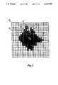
- FIG. 2shows an enlarged image of a spot of contiguous bright pixels.
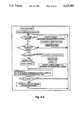
- FIG. 3is a flowchart of the operations which monitor the video signal of the camera to obtain the position of the beginning pixel and ending pixel in each string of contiguous bright pixels obtained from the signal.
- FIG. 4A, FIG. 4B and FIG. 4Cshows flowcharts for a task which outputs the centers and sizes of bright spots of adjacent bright pixels using the positions of their edge pixels.
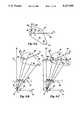
- FIG. 5represent an object containing 4 optically detectable points (FIG. 5A), and show the relationship between these points and their images according to true perspective (FIG. 5B) and according to an approximation of true perspective called scaled orthographic projection (FIG. 5C).
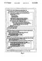
- FIG. 6illustrates a task implementation for assigning the correspondence between image spots and object point light sources when only 4 light sources are used, two of which produce much larger image spots than the other two.
- FIG. 7illustrates the task of finding the correspondence between image spots and light sources of the object when the point light sources have been arranged in two alignments of 3 points with specific ratios in each alignments.
- FIG. 8shows a block diagram for the sequence of operations required for finding the correspondence between image spots and object point light sources when the light sources have been arranged in several alignments of 3 points.
- FIG. 9illustrates the process used for finding the object pose once at least two previous poses have been found.
- FIG. 10is a flowchart of the sequence of operations required for continuously monitoring an object in space during extended periods of time according to this invention.
- FIG. 11is a perspective view of an embodiment for 3D cursor control allowing an operator to interact with a 3D virtual scene shown on a computer display.
- FIG. 12is a perspective view of a pose monitoring system according to this invention applied to monitoring the position and orientation of the head of an operator.
- LEDsLight emitting diodes
- FIG. 1shows an embodiment of the present invention.
- Object 20whose pose in space is being monitored is made of a thin frame 22.
- Light emitting diodes (LEDs) 24of the type which produces light in all directions have been mounted on the frame.
- Object 20is in the field of view of a camera 26, which contains an array of light sensitive elements such as a CCD or CID chip.
- Camera 26outputs a video signal 27.
- Some characteristics of this signalmust be understood in order to follow the principles applied in recovering image information in this embodiment.
- the video part of the signalis a modulated analog signal typically between 0.4 volt and 1 volt, which describes the intensity to be given to the electron beam of a TV monitor as the beam is scanned across the TV screen line by line and from top to bottom.
- a single video imagealso called a video frame, is typically transmitted in the video signal in 1/25 or 1/30 second.
- a frameis generally composed of two interlaced fields which are to be painted on a TV screen one after the other. Pulses called sync pulses are used to indicate the beginning of a new video field and the beginning of each line. During these pulses the signal voltage falls down to a level close to 0 for an interval of several microseconds. Field pulses, indicating the beginning of a new field, are easy to differentiate from line pulses indicating the beginning of a new line, because they typically last more than 5 times longer. Details about video signals and television engineering techniques can be found in "Television Engineering Handbook", by Blair Benson, McGraw-Hill Book Co. The boxes in FIG.
- This devicewould be appropriate only if the detections of the feature points require the different gray levels or colors stored for each pixel in this type of board.
- the paper entitled “Build a Gray-Scale Video Digitizer”, by Steve Ciarcia, published in two parts in Byte of May and June 1987describes the construction of such a device. This paper teaches how to digitize different levels of gray levels in a black and white video image, and therefore describes an electronic construction which has similar functions while being more complex than the electronic construction required for the present embodiment. If the feature points are provided by light sources in a wavelength chosen to produce the highest voltage levels in the video signal, a simplified one level digitizer is sufficient, which produces pixels of level 1 for the bright spots and 0 for the background.
- the present embodimentpreferably contains an electronic device which outputs the columns of the first and last pixels in a string of bright pixels for each row containing bright pixels.
- a task run in a microprocessorcombines these data as they are produced to output the centers of the spots and their size.
- Spot Level Detector 32is a voltage comparator whose output is triggered to a logical high level when the input video signal is above an adjustable threshold level. The threshold level is adjusted so that a logical high is output only for the higher voltage levels in the video signal that correspond to the bright spots of the light sources, and a logical low is output for the voltage levels that are produced by the background of the scene.
- Sync Detector 34is a comparator which outputs a logical high level when the signal voltage falls under 0.2 volts.
- Pixel String Detector 28combines the information provided by Sync Detector 34 and Spot Level Detector 32 with timing information given by a clock and counters to output the locations of the beginning and end pixels of strings of bright pixels.
- FIG. 2the enlarged image of a digitized bright spot 35 is shown.
- Grid lines 36have the purpose of showing the borders of these pixels.
- Bright pixels 38are represented as black squares, and background pixels 40 as white squares.
- the bright spotis composed of several lines of bright pixels, and the strings of bright pixels from one line contain pixels that are contiguous to some of the pixels of the string of a neighbor line.
- Pixels 42 at the beginning of a stringare indicated by a straight cross in FIG. 2, and pixels 44 at the end of a string are indicated by a diagonal cross.
- Some pixels, such as 46,are alone in their string, and being both at the beginning and the end of their strings get marked by a diagonal cross and a straight cross.
- the Pixel String Detector 28For each detected string the Pixel String Detector 28 outputs the line number Y s of occurrence of the string, followed by the column number X b of the beginning pixel of the string and the column number X e of the end pixel of the string.
- Yis the value of the counter for the number of lines
- Xis the counter for the number of columns.
- the variable pixelCountis the total number of columns, i.e. the total number of pixels in a line. If Pixel String Detector 28 checks Spot Level Detector 32 every 200 nanoseconds to see whether its output is high (signifying that the video signal voltage is higher than the threshold level), there is time for checking 256 pixels for each line of video data, an amount which produces a reasonable level of precision in the detection of the spots.
- variable foundString in the flowchartis a boolean variable which becomes true as soon as a bright pixel is found, and becomes false again as soon as a background pixel is found.
- Pixel String Detector 28checks Sync Detector 34 until a field sync pulse is detected. Once this happens Sync Detector 34 is checked again until a line sync pulse is detected. As mentioned earlier, differentiating between field and line sync pulses requires evaluating their lengths, an implementation detail not shown in the flowchart. Once the beginning of a line is found, the line counter Y is incremented and the Spot Level Detector 32 is checked at regular time intervals (for example every 200 nanoseconds) and the pixel counter is incremented each time.
- a spotis an area of contiguous bright pixels, thus it is composed of a single pixel string or a group of strings with contiguous piexels from several image lines.
- the center of the spotis defined here as a point with a veritcal image coordinate equal to the average between the highest and lowest lines of the spot, and a horizontal coordinate equal to the average between the leftmost and rightmost column of the spot. Reading a new pixel string, the code takes one string of the previous line at a time (if any), and looks if its column overlap with the columns of the new string.
- the two stringsbelong to the same spot.
- the two stringsthen share information about the left, right, upper and lower bounds of the groups of pixels to which they each belonged to come out with the left, right, upper and lower bounds of the group of pixels to which they both belong.
- This mechanismsuccessfully groups several distinct pixel strings of one line with a single overlapping string of the next line, a situation which occurs in top lines 4987 of spot 35 in FIG. 2.
- a pixel string of one lineis not contiguous to any string of the next line, or is at the bottom of the image, no more grouping can be found for this string, and the center and size for the corresponding group of pixels is output from the Spot Center Detector.
- pixels 50 that produced extermal values for lines or columnsare marked with a circle, and found center 52 of the spot 35 is indicated by a white square and a diagonal cross. Note that if the center is taken half way between the extrema without rounding to an integer number, its position can fall between pixels, as happens for center 52.
- these spot centersare referred to as image points, and are considered to be the images of the points located at the centers of the light sources of the object.
- Object Pose Module 29 of FIG. 1uses a precomputed matrix 31 which depends only on the relative positions of LEDs 24 on the object to compute the set of parameters that express the position and rotation of the object in the camera coordinate system. These are the 3 coordinates of the translation vector and the 9 elements of rotation matrix 33 in the preferred embodiment as shown on FIG. 1. Details of operations of Object Pose Module 29 are given below.
- FIGS. 5are used to explain the theoretical bases on which the task applied by Object Pose Module 29 is based. In the following explanations of these theoretical bases, bold characters are used for denoting vectors and matrices.
- Points 60 of the object that are visible and easily detected in the camera imageare called M 0 , M 1 , M 2 , M 3 , etc.
- Four pointsare shown for illustration purposes, but the method applies with at least four noncoplanar points and as many noncoplanar points as is wished. Placing LEDs at these locations is one way to make these points visible and easily detectable in the camera image. Placing patches of retroreflective material able to reflect light coming from a single light source is another way to achieve the same result.
- the coordinates of these points in the objectare assumed to be known, and can be defined by their coordinates in a cartesian coordinate system 62 fixed to the object.
- Origin 64 of coordinate system 62is taken to be one of the points, say M 0 .
- This pointwill be called the reference point of the object.
- the reference centerdoes not have to be visible itself, but can be chosen to be a linear combination of the visible points, such as the center of gravity of the visible points.
- the image of the reference centercan be taken to be the same linear combination of the images of the visible points, such as the center of gravity of the images of the visible points.
- one of the visible pointssuch as M0 has been chosen as a reference point.
- Axes 66are called M 0 X 0 , M 0 Y 0 and M 0 Z 0 .
- Unit vectors 68 of this coordinate systemare called i 0 , j 0 , and k 0 .
- the coordinates of M 0 in object coordinate 62 systemare (0, 0, 0).
- the vector M 0 M 1has coordinates X 1 , Y 1 and Z 1 , written (X 1 , Y 1 , Z 1 ).
- M 0 M 2has coordinates (X 2 , Y 2 , Z 2 ), and so on.
- FIG. 5BThe notations for the geometric construction used for modelling the image formation process in the camera are shown in FIG. 5B.
- This image formation processis modelled using the pinhole camera model, a reasonable assumption widely used in the field of computer vision. For details, see for example the book “Computer Vision”, by Ballard and Brown, Prentice-Hall.
- the imaging processis simply a central projection in which the center of projection is the pinhole of the camera, and the projection plane is the image plane of the camera. This central projection is also called perspective projection.
- center of projection 70is labelled O
- image plane 72is labelled J.
- image plane 72is drawn on the same side of the center of projection O (72) as points 60 of object 20, whereas in an actual pinhole camera the image plane is on the other side of the center of projection, with the result that the image is inverted.
- the imageconsists of the central projection of points 60 of object on image plane J.
- image m1 in image plane J of a point M 1 in front of the camerais constructed by taking the intersection of a ray from point M 1 to center of projection O with image plane J, as shown in FIG. 5B.
- Coordinate system 74 of camera 26is shown to be centered in O, and has axes Ox and Oy parallel to the image plane J and axis Oz perpendicular to the image plane J.
- axes Ox and Ozare shown to be parallel to the plane of the figures.
- Optical axis 76 of camera 26is axis Oz.
- Focal length f of camera 26is the z-coordinate of image plane J.
- Unit vectors 78 of camera coordinate system 74are i for the axis Ox and k for Oz.
- Unit vector j of axis Oyis perpendicular to the plane of the paper and could not be shown.
- the position of image point m 0 in image plane Jis defined by its coordinates x 0 and y 0 , the position of image point m 1 by coordinates x 1 and y 1 , etc.
- a plane K (80) parallel to image plane Jis taken through one of the points of the object, say M 0 , and the points of the object are projected onto this plane by perpendicular projection.
- This projectionis called an orthographic projection.
- the projections of M 0 , M 1 , M 2 , M 3are P 0 , P 1 , P 2 , P 3 in FIG. 5C. (M 0 and P 0 are superposed since M 0 belongs to the plane of projection).
- the distance from plane K to center of projection Ois called D.
- points P 0 , P 1 , P 2 , P 3are projected onto image plane J by an exact perspective projection, and give projections m 0 , m 1 , m 2 , m 3 that are close to the projections that would be obtained by directly projecting M 0 , M 1 , M 2 , M 3 onto image plane J.
- the information which is available for finding the unknown object poseis the following: As previously explained the coordinates of object points M 1 , M 2 , etc., in the coordinate system of the object are known by preliminary measurements. The coordinates (x 1 , y 1 ), (x 2 ,y 2 ), etc. of image points m 1 , m 2 , etc., are given by the analysis of the video signal described earlier. Furthermore an image point such as m 1 is known to be the image of object point M 1 and no other point, similarly for m 2 and M 2 , etc.
- the translation vector of the objectis the vector OM 0 for which the coordinates in the camera coordinate system must be found.
- the row vectors of the rotation matrixare simply the unit vectors i, j, k, of the camera coordinate system expressed in the coordinate system of the object. Therefore the following paragraphs explain how to solve for these yet unknown vectors from the known image and object information just reviewed.
- the x and y coordinates of vector P 0 P 1 in camera coordinate system 74are the same as the x and y coordinates of the vector M 0 M 1 .
- these coordinatesare the projections of vector M 0 M 1 on unit vectors i and j of the camera.
- the z-coordinate of P 0 P 1is 0, since this vector belongs to a plane that is perpendicular to the z-axis of camera coordinate system 74. Therefore the coordinates of P 0 P 1 are (M 0 M 1 ⁇ i, M 0 M 1 ⁇ j, 0), where the dot notation expresses a dot product operation between vectors.
- Vectors V x and V yare now defined as scaled down versions of unit vectors i and j:
- I xis the vector with coordinates (x 1 -x 0 ,x 2 -x 0 ,x 3 -x 0 , . . . ) and the vector I y is the vector with coordinates (y 1 -y 0 ,y 2 -y 0 ,y 3 -y 0 , . . . ).
- Vectors I x and I yare called the image x-vector and the image y-vector in this disclosure.
- Matrix Ais a matrix in which the first row has 3 elements that are the 3 coordinates of object point M 1 , the second row has 3 elements that are the 3 coordinates of object point M 2 , and so on for the other rows.
- i and jare simply obtained by normalizing V x and V y , since i and j are unit vectors.
- the 3 elements of the first row of the rotation matrix of the objectare then the 3 coordinates of vector i obtained in this fashion.
- the 3 elements of the second row of the rotation matrixare the 3 coordinates of vector j.
- the elements of the third roware the coordinates of vector k of the z-axis of camera coordinate system 74 and are therefore obtained by taking the cross-product of vectors i and j.
- the translation vector of the objectcan be obtained. It is vector OM 0 between center of projection O and M 0 origin of object coordinate system 62. Since m 0 , image point of M 0 , belongs to image plane J at a distance f from center of projection O, and MO belongs to plane K parallel to J at a distance D from O (FIG. 5C), translation vector OM 0 is aligned with vector Om 0 and is equal to D.f OM 0 i.e. 1/s OM 0 . Scale factor s is obtained by taking the norm of vector V x or vector V y .
- the first coordinate of the image x-vectormust use x-coordinate of the image of the object point used in the first row of the matrix A that yields the object matrix B after pseudo-inversion, and so on, and similarly for the image y-vector. Only with this order will the scale factor obtained as the norm of the vector V x and the scale factor obtained as the norm of the vector V y be equal (within processing errors), and only with this order will the vectors i and j be perpendicular. In other words with this order, vectors V x and V y defined above are perpendicular and of equal lengths. In the preferred embodiment a positive correspondence measure C which becomes small when both of these conditions are met is defined. The preferred way to build such a quantity is
- the object pose computationis applied to each of several candidate correspondence assignments, and the calculated pose of the object that is accepted as the object pose is the one for which the correspondence measure is small.
- FIG. 6a simple embodiment for the correspondence assignment task is presented in which the correspondence combinations are small and can be all examined. If 4 LEDs 24 are used and 4 image spots 35 are detected, there are 24 possible assignments between the image spots and the object LEDs, so that computing 24 poses and keeping the pose that produces the smallest correspondence measure C as proposed may be too time consuming in inexpensive computers.
- the combinationscan be reduced if two categories of LEDs are used and these categories are easily discriminated in the image. For example in one embodiment large and small LEDs are used, producing large and small image spots with easily differentiable spot sizes. For the case of two large and two small LEDs, the 4 possible assignments are shown in the box in FIG. 6. These assignments are then discriminated by comparing the correspondence measures C for the computed poses (defined above).
- FIG. 7shows a correspondence assignment embodiment which is based on using several alignments 61 of object points 60, and ratios of distances between points within each alignment.
- Aligned object points 61produce aligned image points 63.
- the same harmonic distance ratiosare found between 4 aligned object points and the corresponding image points.
- Two alignments of 4 object pointscan be constructed with very distinct harmonic ratios, so that each image alignment can be easily assigned to its corresponding object alignment.
- Alignments of 3 pointscan also be considered, but the ratios of distances between 3 points are only approximately preserved in perspective projection. Yet when there are only two alignments in the object, it is possible to choose two very different ratios so that the discrimination is still possible in the image.
- an object point of one alignmentmay project into the image alignment of another alignment.
- point C in FIG. 7projects into image point c on on image plane 72.
- Image point cis common to the two image alignments.
- the tables which appear next to the drawing in FIG. 7show the image alignments of 3 points found in the image, the ratios found for each, the possible matches of these triples with the object alignments, and the best correspondence.
- the second best correspondencecan be easily rejected on the basis that the image point b would be matched both to point C and to point D, indicating that two object points project to the same image points. This is unlikely since as many image points as object points were found.
- FIG. 8shows in a flowchart the sequence of steps necessary to find alignments of 3 points in the image, order the points in the alignments, compute the distance ratios, match the image alignments to the object alignments on the base of these ratios, and select the best correspondence assignment.
- a similar sequenceis required if alignments of 4 points and harmonic ratios are used instead.
- the systemapplies a tracking technique illustrated in FIG. 9, which avoids rechecking the correspondence assignments between object points and image points. From these previous object poses, the system approximately predicts what the pose will be once a new image is processed, by extrapolating the previous poses. From this predicted pose, the object points 60 are projected onto image plane 72 to obtain predicted image spot locations 82. From the estimations of the prediction uncertainties, uncertainty squares 84 are defined around each predicted point and chosen large enough to contain the actual spot centers with high confidence. Considering the list of uncertainty squares against the list of image points (found by the part of the system described in reference to FIG. 1), the object point used in computing the uncertainty square is matched with the image spot which falls into it.
- the computed posewill deteriorate if more and more image points exit the boundaries of the image or get obstructed, up to the moment when the computed pose is not good enough for successfully tracking the image points that remain visible. At that moment, the system has to wait until all the image points are visible again in the image to be able to compute the object pose. When this occurs, the system applies the correspondence assignment techniques described earlier for several images, then starts a new tracking sequence.
- FIG. 10a flowchart is shown which includes the computation steps for the initial images in which correspondence techniques are applied, and the succeeding images in which tracking techniques are applied which keep track of each spot separately and make other correspondence techniques unnecessary.
- a box in this flowchartindicates where the cursor would be redrawn in a cursor control implementation such as illustrated in FIG. 11, and obviously this step would be replaced by different actions in other applications, such as refreshing the graphics displayed to the operator in virtual reality applications using for example the device of FIG. 12, or sending control commands to a teleoperated system.
- the operations required at each step of FIG. 10have already been detailed in the explanations of the previous Figures.
- Camera 26is positioned next to computer display 88 and faces the operator.
- Object 20is composed of a frame 22 supporting several LEDs 24.
- Frame 22is preferably composed of thin or transparent structure in order to minimize the chances that the frame be on the way of the view of a LED by the camera.
- a handle 92is attached to object 20, and is held in hand 90 of the operator. Batteries that power the LEDs are contained in handle 92.
- LEDs 24may emit light in the infrared range instead of the visible light range and the sensing array for camera 26 may be chosen to be more sensitive to infrared light than to visible light so that the response of the camera array to the LEDs is large in comparison to the response to background light and so that the spots created by the LEDs in the image are much brighter than the background even when the operator works in ambient light.
- the device processing the camera signal and computing the object pose according to this inventionis not shown and is implemented on a printed circuit board which may be enclosed in the camera housing, in an independent housing, or inside the main computer. The positions and orientations in space of object 20 are computed at successive time intervals as described above.
- a screen cursor 94is shown on the computer display among perspective views of 3D objects, a cuboid peg 96 and a block 97.
- Screen cursor 94is the perspective projection of a virtual 3D cursor of known 3D structure that is rigidly linked to object 20, so that the computed object position and orientation are taken to be the position and orientation for the virtual 3D cursor at every instant.
- the 3D cursoris a stick figure of a man with a spherical head holding in his right hand an arrow that is perpendicular to the plane of his object and points in front of him.
- Screen cursor 94is obtained from the virtual 3D cursor by the same perspective projection that is used for the other 3D objects of the virtual 3D scene represented on the computer display.
- the operatorhas attached the 3D cursor to cuboid peg 96, and is inserting peg 96 into the rectangular hole of block 97.
- the operatorcan also remotely and interactively control the motions of a teleoperated mechanism, provided servomechanisms translate the 3D motions of the 3D cursor computed by the system into mirrored mechanical displacements of the teleoperated mechanism.
- FIG. 12another embodiment of the pose monitoring system is illustrated, in which the position and orientation in space of the head of an operator is monitored.
- Applicationsinclude aircraft flight simulators and other virtual reality applications. From the translation vector and rotation matrix computed by the system for the head of the operator, the correct field of view and perspective projection of the virtual scene are computed and projected in front of the eyes of the operator.
- Two noncoplanar alignments 61 of LEDs 24are mounted on the top surface of a helmet 98.
- Camera 26mounted above operator's helmet 98 captures the images of LEDs 24. With judicious camera placement, the LEDs may be mounted on an opaque support as is shown in the drawing without risk of the support obstructing the view of the LEDs, because the ranges of the operator's head motions in tilt and roll are anatomically limited.
- the light sources on the objectcould be light-emitting bars
- the cameracould use an array of light sensitive random access memory elements
- the processing taskscould be implemented in Programmable Array Logic chips, etc.
Landscapes
- Physics & Mathematics (AREA)
- Electromagnetism (AREA)
- Engineering & Computer Science (AREA)
- General Physics & Mathematics (AREA)
- Radar, Positioning & Navigation (AREA)
- Remote Sensing (AREA)
- Length Measuring Devices By Optical Means (AREA)
Abstract
Description
s=f/D
x.sub.1 -x.sub.0 =sM.sub.0 M.sub.1 ·i,
y.sub.1 -y.sub.0 =sM.sub.0 M.sub.1 ·j
V.sub.x =si,
V.sub.y =sj
x.sub.1 -x.sub.0 =M.sub.0 M.sub.1 ·V.sub.x,
y.sub.1 -y.sub.0 =M.sub.0 M.sub.1 ·V.sub.y
x.sub.2 -x.sub.0 =M.sub.0 M.sub.2 ·V.sub.x,
y.sub.2 -y.sub.0 =M.sub.0 M.sub.2 ·V.sub.y
I.sub.x =A V.sub.x,
I.sub.y =A V.sub.y
V.sub.x =B I.sub.x,
V.sub.y =B I.sub.y
C=|V.sub.x ·V.sub.y |+|V.sub.x ·V.sub.x -V.sub.y ·V.sub.y |
Claims (15)
Priority Applications (1)
| Application Number | Priority Date | Filing Date | Title |
|---|---|---|---|
| US07/747,124US5227985A (en) | 1991-08-19 | 1991-08-19 | Computer vision system for position monitoring in three dimensions using non-coplanar light sources attached to a monitored object |
Applications Claiming Priority (1)
| Application Number | Priority Date | Filing Date | Title |
|---|---|---|---|
| US07/747,124US5227985A (en) | 1991-08-19 | 1991-08-19 | Computer vision system for position monitoring in three dimensions using non-coplanar light sources attached to a monitored object |
Publications (1)
| Publication Number | Publication Date |
|---|---|
| US5227985Atrue US5227985A (en) | 1993-07-13 |
Family
ID=25003742
Family Applications (1)
| Application Number | Title | Priority Date | Filing Date |
|---|---|---|---|
| US07/747,124Expired - LifetimeUS5227985A (en) | 1991-08-19 | 1991-08-19 | Computer vision system for position monitoring in three dimensions using non-coplanar light sources attached to a monitored object |
Country Status (1)
| Country | Link |
|---|---|
| US (1) | US5227985A (en) |
Cited By (310)
| Publication number | Priority date | Publication date | Assignee | Title |
|---|---|---|---|---|
| US5297061A (en)* | 1993-05-19 | 1994-03-22 | University Of Maryland | Three dimensional pointing device monitored by computer vision |
| US5325133A (en)* | 1991-10-07 | 1994-06-28 | Konami Co., Ltd. | Device for measuring a retina reflected light amount and a gaze detecting apparatus using the same |
| US5353042A (en)* | 1992-12-02 | 1994-10-04 | Klapman Matthew H | Method for determining an orientation of an object |
| DE4315005A1 (en)* | 1993-05-06 | 1994-11-10 | Deutsche Aerospace | Device for measuring angular positions of a moving object with respect to its initial position |
| US5388059A (en)* | 1992-12-30 | 1995-02-07 | University Of Maryland | Computer vision system for accurate monitoring of object pose |
| US5423554A (en)* | 1993-09-24 | 1995-06-13 | Metamedia Ventures, Inc. | Virtual reality game method and apparatus |
| US5454043A (en)* | 1993-07-30 | 1995-09-26 | Mitsubishi Electric Research Laboratories, Inc. | Dynamic and static hand gesture recognition through low-level image analysis |
| DE4411907A1 (en)* | 1994-04-07 | 1995-10-12 | Alexander Dr Hohensee | Determining rotation axis of human joint with variable axis position |
| FR2718519A1 (en)* | 1994-04-12 | 1995-10-13 | Thomson Csf | Sighting system for helmet with viewing screen for user of firearm |
| US5546808A (en)* | 1994-09-06 | 1996-08-20 | Harris Instrument Corporation | Apparatus and method for binocular measurement system |
| US5550560A (en)* | 1993-02-12 | 1996-08-27 | International Business Machines Corporation | Image displaying apparatus |
| US5577981A (en)* | 1994-01-19 | 1996-11-26 | Jarvik; Robert | Virtual reality exercise machine and computer controlled video system |
| WO1996040527A1 (en)* | 1995-06-07 | 1996-12-19 | Acushnet Company | Apparatus for the spatial orientation and manipulation of a game ball |
| US5617312A (en)* | 1993-11-19 | 1997-04-01 | Hitachi, Ltd. | Computer system that enters control information by means of video camera |
| WO1997024682A1 (en)* | 1995-12-27 | 1997-07-10 | Romanik, Carl, J., Jr. | Optical system for accurate monitoring of the position and orientation of an object |
| WO1997036224A1 (en)* | 1996-03-26 | 1997-10-02 | Viktor Alexeevich Kuzin | Device for inputting information to a controlled system |
| US5674335A (en)* | 1995-01-06 | 1997-10-07 | Aman; James A. | Automated end labeler system |
| US5704836A (en)* | 1995-03-23 | 1998-01-06 | Perception Systems, Inc. | Motion-based command generation technology |
| WO1998013746A1 (en)* | 1996-09-27 | 1998-04-02 | Samsung Electronics Co. Ltd. | Method for feeding information into a computer |
| US5764217A (en)* | 1995-01-23 | 1998-06-09 | International Business Machines Corporation | Schematic guided control of the view point of a graphics processing and display system |
| US5803810A (en)* | 1995-03-23 | 1998-09-08 | Perception Systems, Inc. | Velocity-based command recognition technology |
| US5818424A (en)* | 1995-10-19 | 1998-10-06 | International Business Machines Corporation | Rod shaped device and data acquisition apparatus for determining the position and orientation of an object in space |
| US5828770A (en)* | 1996-02-20 | 1998-10-27 | Northern Digital Inc. | System for determining the spatial position and angular orientation of an object |
| US5832139A (en)* | 1996-07-31 | 1998-11-03 | Omniplanar, Inc. | Method and apparatus for determining degrees of freedom of a camera |
| GB2325807A (en)* | 1997-05-30 | 1998-12-02 | British Broadcasting Corp | Position determination |
| WO1998054593A1 (en)* | 1997-05-30 | 1998-12-03 | British Broadcasting Corporation | Position determination |
| US5856844A (en)* | 1995-09-21 | 1999-01-05 | Omniplanar, Inc. | Method and apparatus for determining position and orientation |
| EP0886829A4 (en)* | 1995-09-27 | 1999-01-20 | ||
| US5867274A (en)* | 1997-02-14 | 1999-02-02 | Harris Instrument Corporation | System for the measurement of the cut length of moving articles |
| WO1999014939A1 (en)* | 1997-09-12 | 1999-03-25 | Orad Hi-Tec Systems Limited | Virtual studio position sensing system |
| US5889550A (en)* | 1996-06-10 | 1999-03-30 | Adaptive Optics Associates, Inc. | Camera tracking system |
| EP0813040A3 (en)* | 1996-06-14 | 1999-05-26 | Xerox Corporation | Precision spatial mapping with combined video and infrared signals |
| US5923324A (en)* | 1997-04-04 | 1999-07-13 | International Business Machines Corporation | Viewer interactive three-dimensional workspace with interactive three-dimensional objects and corresponding two-dimensional images of objects in an interactive two-dimensional workplane |
| US5929444A (en)* | 1995-01-31 | 1999-07-27 | Hewlett-Packard Company | Aiming device using radiated energy |
| US5963194A (en)* | 1993-11-25 | 1999-10-05 | Alps Electric Co. Ltd. | Apparatus for inclination detection and input apparatus using this apparatus |
| US5982352A (en)* | 1992-09-18 | 1999-11-09 | Pryor; Timothy R. | Method for providing human input to a computer |
| US5991085A (en) | 1995-04-21 | 1999-11-23 | I-O Display Systems Llc | Head-mounted personal visual display apparatus with image generator and holder |
| US6009210A (en)* | 1997-03-05 | 1999-12-28 | Digital Equipment Corporation | Hands-free interface to a virtual reality environment using head tracking |
| WO2000016121A1 (en)* | 1998-09-11 | 2000-03-23 | Qualisys Ab | System relating to positioning in a virtual studio |
| US6061644A (en)* | 1997-12-05 | 2000-05-09 | Northern Digital Incorporated | System for determining the spatial position and orientation of a body |
| US6072903A (en)* | 1997-01-07 | 2000-06-06 | Kabushiki Kaisha Toshiba | Image processing apparatus and image processing method |
| EP0949513A3 (en)* | 1998-04-08 | 2000-09-27 | Trisen Systems Inc. | Virtual reality technology |
| US6130663A (en)* | 1997-07-31 | 2000-10-10 | Null; Nathan D. | Touchless input method and apparatus |
| US6147716A (en)* | 1997-05-23 | 2000-11-14 | Sony Corporation | Picture generator and picture generation method |
| US6201882B1 (en)* | 1997-07-23 | 2001-03-13 | Nec Corporation | Camera calibration apparatus |
| US6216053B1 (en)* | 1992-11-09 | 2001-04-10 | Lextron, Inc. | Apparatus and method for uniformly delivering feed rations along a feedbunk using global positioning system |
| US6232959B1 (en)* | 1995-04-03 | 2001-05-15 | Steinar Pedersen | Cursor control device for 2-D and 3-D applications |
| US6236737B1 (en) | 1997-03-26 | 2001-05-22 | Dalhousie University | Dynamic target addressing system |
| US6240198B1 (en) | 1998-04-13 | 2001-05-29 | Compaq Computer Corporation | Method for figure tracking using 2-D registration |
| US6243106B1 (en)* | 1998-04-13 | 2001-06-05 | Compaq Computer Corporation | Method for figure tracking using 2-D registration and 3-D reconstruction |
| US6243491B1 (en)* | 1996-12-31 | 2001-06-05 | Lucent Technologies Inc. | Methods and apparatus for controlling a video system with visually recognized props |
| US6256418B1 (en) | 1998-04-13 | 2001-07-03 | Compaq Computer Corporation | Method and system for compressing a sequence of images including a moving figure |
| US6269172B1 (en) | 1998-04-13 | 2001-07-31 | Compaq Computer Corporation | Method for tracking the motion of a 3-D figure |
| US6327097B1 (en)* | 1997-04-17 | 2001-12-04 | Zbig Vision Gesellschaft Fur Neue Bildgestaltung Mbh | Optical imaging system and graphic user interface |
| US6335977B1 (en)* | 1997-05-28 | 2002-01-01 | Mitsubishi Denki Kabushiki Kaisha | Action recognizing apparatus and recording medium in that action recognizing program is recorded |
| WO2002025306A1 (en)* | 2000-09-20 | 2002-03-28 | Faeger Jan G | A device and a method for producing information about the properties of an environment |
| US6400374B2 (en) | 1996-09-18 | 2002-06-04 | Eyematic Interfaces, Inc. | Video superposition system and method |
| US20020071594A1 (en)* | 2000-10-12 | 2002-06-13 | Allen Kool | LS tracker system |
| US20020074233A1 (en)* | 1998-02-04 | 2002-06-20 | Semitool, Inc. | Method and apparatus for low temperature annealing of metallization micro-structures in the production of a microelectronic device |
| US6411744B1 (en)* | 1997-10-15 | 2002-06-25 | Electric Planet, Inc. | Method and apparatus for performing a clean background subtraction |
| US6417836B1 (en) | 1999-08-02 | 2002-07-09 | Lucent Technologies Inc. | Computer input device having six degrees of freedom for controlling movement of a three-dimensional object |
| US6424410B1 (en) | 1999-08-27 | 2002-07-23 | Maui Innovative Peripherals, Inc. | 3D navigation system using complementary head-mounted and stationary infrared beam detection units |
| WO2002063456A1 (en)* | 2001-02-08 | 2002-08-15 | Anderson Technologies Pty Ltd | Optical tracking computer interface |
| WO2002068987A1 (en)* | 2001-02-23 | 2002-09-06 | Industrial Control Systems Limited | Apparatus and method for obtaining three-dimensional positional data from a two-dimensional captured image |
| GB2379493A (en)* | 2001-09-06 | 2003-03-12 | 4D Technology Systems Ltd | Controlling an electronic device by detecting a handheld member with a camera |
| EP1085405A3 (en)* | 1999-09-13 | 2003-08-06 | Solidworks Corporation | Electronic drawing viewer |
| US20030210255A1 (en)* | 2002-03-26 | 2003-11-13 | Sony Corporation | Image display processing apparatus, image display processing method, and computer program |
| US6671651B2 (en)* | 2002-04-26 | 2003-12-30 | Sensable Technologies, Inc. | 3-D selection and manipulation with a multiple dimension haptic interface |
| US20040044724A1 (en)* | 2002-08-27 | 2004-03-04 | Bell Cynthia S. | Apparatus and methods to exchange menu information among processor-based devices |
| US20040044723A1 (en)* | 2002-08-27 | 2004-03-04 | Bell Cynthia S. | User interface to facilitate exchanging files among processor-based devices |
| US20040041788A1 (en)* | 2002-08-28 | 2004-03-04 | Lockheed Martin Corporation | Interactive virtual portal |
| US20040051680A1 (en)* | 2002-09-25 | 2004-03-18 | Azuma Ronald T. | Optical see-through augmented reality modified-scale display |
| US6710765B1 (en)* | 1999-10-05 | 2004-03-23 | Nippon Telegraph And Telephone Corporation | Input device of 3-D translation and rotation and its method and recording medium |
| EP1402929A1 (en)* | 2002-09-30 | 2004-03-31 | Xiaoling Wang | An apparatus and a method for more realistic interactive video games on computers or similar devices |
| US20040068758A1 (en)* | 2002-10-02 | 2004-04-08 | Mike Daily | Dynamic video annotation |
| US20040066391A1 (en)* | 2002-10-02 | 2004-04-08 | Mike Daily | Method and apparatus for static image enhancement |
| US6727885B1 (en) | 1999-09-07 | 2004-04-27 | Nikon Corporation | Graphical user interface and position or attitude detector |
| US20040102911A1 (en)* | 2002-11-21 | 2004-05-27 | Samsung Electronics Co., Ltd. | Hand/eye calibration method using projective invariant shape descriptor of 2-dimensional image |
| WO2003104965A3 (en)* | 2002-06-08 | 2004-06-10 | Robert Michael Lipman | Computer navigation |
| US6750848B1 (en) | 1998-11-09 | 2004-06-15 | Timothy R. Pryor | More useful man machine interfaces and applications |
| US20040130579A1 (en)* | 2002-12-19 | 2004-07-08 | Shinya Ishii | Apparatus, method, and program for processing information |
| US20050024379A1 (en)* | 2000-07-21 | 2005-02-03 | Marks Richard L. | Method for color transition detection |
| US20050043956A1 (en)* | 2003-07-03 | 2005-02-24 | Sony Corporation | Speech communiction system and method, and robot apparatus |
| US20050156914A1 (en)* | 2002-06-08 | 2005-07-21 | Lipman Robert M. | Computer navigation |
| WO2005094176A2 (en) | 2004-04-01 | 2005-10-13 | Power2B, Inc | Control apparatus |
| WO2005116809A2 (en) | 2004-05-24 | 2005-12-08 | 3D For All Számítástechnikai Fejlesztö Kft. | System and method for operating in virtual 3d space and system for selecting an operation via a visualizing system |
| US20060023111A1 (en)* | 2004-07-28 | 2006-02-02 | The University Of Maryland | Device using a camera and light polarization for the remote displacement of a cursor on a display |
| US20060055699A1 (en)* | 2004-09-15 | 2006-03-16 | Perlman Stephen G | Apparatus and method for capturing the expression of a performer |
| US20060055706A1 (en)* | 2004-09-15 | 2006-03-16 | Perlman Stephen G | Apparatus and method for capturing the motion of a performer |
| US20060072124A1 (en)* | 2004-10-01 | 2006-04-06 | Smetak Edward C | System and tracker for tracking an object, and related methods |
| US20060082546A1 (en)* | 2003-06-23 | 2006-04-20 | Fun Wey | Computer input device tracking six degrees of freedom |
| US20060105849A1 (en)* | 2004-11-17 | 2006-05-18 | Wolfgang Brunner | Position determination system and ball sport training system |
| US20060119574A1 (en)* | 2004-12-06 | 2006-06-08 | Naturalpoint, Inc. | Systems and methods for using a movable object to control a computer |
| US20060119575A1 (en)* | 2004-12-06 | 2006-06-08 | Naturalpoint, Inc. | Systems and methods for using a movable object to control a computer |
| US7098891B1 (en)* | 1992-09-18 | 2006-08-29 | Pryor Timothy R | Method for providing human input to a computer |
| US20060192854A1 (en)* | 2005-02-25 | 2006-08-31 | Perlman Stephen G | Apparatus and method improving marker identification within a motion capture system |
| US20060209052A1 (en)* | 2005-03-18 | 2006-09-21 | Cohen Alexander J | Performing an action with respect to a hand-formed expression |
| US20060209042A1 (en)* | 2005-03-18 | 2006-09-21 | Searete Llc, A Limited Liability Corporation Of The State Of Delaware | Handwriting regions keyed to a data receptor |
| US20060239471A1 (en)* | 2003-08-27 | 2006-10-26 | Sony Computer Entertainment Inc. | Methods and apparatus for targeted sound detection and characterization |
| US7133043B1 (en)* | 1999-11-29 | 2006-11-07 | Microsoft Corporation | Computer graphics methods and apparatus for ray intersection |
| US20060264260A1 (en)* | 2002-07-27 | 2006-11-23 | Sony Computer Entertainment Inc. | Detectable and trackable hand-held controller |
| US20060264259A1 (en)* | 2002-07-27 | 2006-11-23 | Zalewski Gary M | System for tracking user manipulations within an environment |
| US20060264258A1 (en)* | 2002-07-27 | 2006-11-23 | Zalewski Gary M | Multi-input game control mixer |
| US20060269072A1 (en)* | 2003-08-27 | 2006-11-30 | Mao Xiao D | Methods and apparatuses for adjusting a listening area for capturing sounds |
| US20060267964A1 (en)* | 2005-05-25 | 2006-11-30 | Searete Llc, A Limited Liability Corporation Of The State Of Delaware | Performing an action with respect to hand-formed expression |
| US20060269073A1 (en)* | 2003-08-27 | 2006-11-30 | Mao Xiao D | Methods and apparatuses for capturing an audio signal based on a location of the signal |
| US20060277571A1 (en)* | 2002-07-27 | 2006-12-07 | Sony Computer Entertainment Inc. | Computer image and audio processing of intensity and input devices for interfacing with a computer program |
| US20060274911A1 (en)* | 2002-07-27 | 2006-12-07 | Xiadong Mao | Tracking device with sound emitter for use in obtaining information for controlling game program execution |
| US20060280312A1 (en)* | 2003-08-27 | 2006-12-14 | Mao Xiao D | Methods and apparatus for capturing audio signals based on a visual image |
| US20060282873A1 (en)* | 2002-07-27 | 2006-12-14 | Sony Computer Entertainment Inc. | Hand-held controller having detectable elements for tracking purposes |
| US20060287085A1 (en)* | 2002-07-27 | 2006-12-21 | Xiadong Mao | Inertially trackable hand-held controller |
| US20060287086A1 (en)* | 2002-07-27 | 2006-12-21 | Sony Computer Entertainment America Inc. | Scheme for translating movements of a hand-held controller into inputs for a system |
| US20060287087A1 (en)* | 2002-07-27 | 2006-12-21 | Sony Computer Entertainment America Inc. | Method for mapping movements of a hand-held controller to game commands |
| US20060287084A1 (en)* | 2002-07-27 | 2006-12-21 | Xiadong Mao | System, method, and apparatus for three-dimensional input control |
| US20070015559A1 (en)* | 2002-07-27 | 2007-01-18 | Sony Computer Entertainment America Inc. | Method and apparatus for use in determining lack of user activity in relation to a system |
| US20070015558A1 (en)* | 2002-07-27 | 2007-01-18 | Sony Computer Entertainment America Inc. | Method and apparatus for use in determining an activity level of a user in relation to a system |
| US20070021208A1 (en)* | 2002-07-27 | 2007-01-25 | Xiadong Mao | Obtaining input for controlling execution of a game program |
| CN1300551C (en)* | 2002-07-25 | 2007-02-14 | 索卢申力士公司 | Apparatus and method for automatically arranging three dimensional scan data using optical marker |
| US20070035562A1 (en)* | 2002-09-25 | 2007-02-15 | Azuma Ronald T | Method and apparatus for image enhancement |
| WO2007029257A2 (en) | 2005-09-08 | 2007-03-15 | Power2B, Inc. | Displays and information input devices |
| US20070058047A1 (en)* | 2004-10-25 | 2007-03-15 | Henty David L | Multi-directional remote control system and method |
| US20070097106A1 (en)* | 2005-11-03 | 2007-05-03 | Honeywell International Inc. | Constant point in space lateral map lighting |
| US20070126717A1 (en)* | 2005-03-18 | 2007-06-07 | Searete Llc, A Limited Liability Corporation Of The State Of Delaware | Including contextual information with a formed expression |
| US20070146370A1 (en)* | 2005-12-23 | 2007-06-28 | Demian Gordon | Group tracking in motion capture |
| US20070177133A1 (en)* | 2006-02-01 | 2007-08-02 | Gary Cain | Position indicating and guidance system and method thereof |
| US20070217657A1 (en)* | 2001-05-23 | 2007-09-20 | Kabushiki Kaisha Toshiba | System and method for detecting obstacle |
| US20070218994A1 (en)* | 2006-03-14 | 2007-09-20 | Sony Computer Entertainment Inc. | Game Controller |
| US20070223732A1 (en)* | 2003-08-27 | 2007-09-27 | Mao Xiao D | Methods and apparatuses for adjusting a visual image based on an audio signal |
| US20070239169A1 (en)* | 2006-03-17 | 2007-10-11 | Perception Raisonnement Action En Medecine | Reference marker and use in a motion tracking system |
| US7292151B2 (en) | 2004-07-29 | 2007-11-06 | Kevin Ferguson | Human movement measurement system |
| US20070256263A1 (en)* | 2004-05-29 | 2007-11-08 | Braun Gmbh | Brush Head for Electric and/or Manual Toothbrushes |
| US20080048931A1 (en)* | 2003-11-26 | 2008-02-28 | Rafael - Armament Development Authority Ltd. | Helmet System for Information or Weapon Systems |
| US20080065992A1 (en)* | 2006-09-11 | 2008-03-13 | Apple Computer, Inc. | Cascaded display of video media |
| US20080080789A1 (en)* | 2006-09-28 | 2008-04-03 | Sony Computer Entertainment Inc. | Object detection using video input combined with tilt angle information |
| US20080088587A1 (en)* | 2001-02-22 | 2008-04-17 | Timothy Pryor | Compact rtd instrument panels and computer interfaces |
| US20080088604A1 (en)* | 2006-10-11 | 2008-04-17 | Searete Llc, A Limited Liability Corporation | Contextual information encoded in a formed expression |
| US20080098448A1 (en)* | 2006-10-19 | 2008-04-24 | Sony Computer Entertainment America Inc. | Controller configured to track user's level of anxiety and other mental and physical attributes |
| US20080096654A1 (en)* | 2006-10-20 | 2008-04-24 | Sony Computer Entertainment America Inc. | Game control using three-dimensional motions of controller |
| US20080096657A1 (en)* | 2006-10-20 | 2008-04-24 | Sony Computer Entertainment America Inc. | Method for aiming and shooting using motion sensing controller |
| US20080100825A1 (en)* | 2006-09-28 | 2008-05-01 | Sony Computer Entertainment America Inc. | Mapping movements of a hand-held controller to the two-dimensional image plane of a display screen |
| US20080122799A1 (en)* | 2001-02-22 | 2008-05-29 | Pryor Timothy R | Human interfaces for vehicles, homes, and other applications |
| US20080129704A1 (en)* | 1995-06-29 | 2008-06-05 | Pryor Timothy R | Multipoint, virtual control, and force based touch screen applications |
| US20080188934A1 (en)* | 2004-04-22 | 2008-08-07 | Walter Moser | Device For Ascertaining A Force-Displacement Characteristic Curve Of One Or More Ligaments, And Method Of Doing The Same |
| US20080211779A1 (en)* | 1994-08-15 | 2008-09-04 | Pryor Timothy R | Control systems employing novel physical controls and touch screens |
| US7426532B2 (en) | 2002-08-27 | 2008-09-16 | Intel Corporation | Network of disparate processor-based devices to exchange and display media files |
| WO2007130872A3 (en)* | 2006-05-04 | 2008-11-20 | Sony Comp Entertainment Us | Method and apparatus for use in determining lack of user activity, determining an activity level of a user, and/or adding a new player in relation to a system |
| US20090009469A1 (en)* | 2007-07-06 | 2009-01-08 | Microsoft Corporation | Multi-Axis Motion-Based Remote Control |
| US7499828B2 (en) | 2005-11-29 | 2009-03-03 | Mario Barton | Position determining apparatus and related method |
| US20090062943A1 (en)* | 2007-08-27 | 2009-03-05 | Sony Computer Entertainment Inc. | Methods and apparatus for automatically controlling the sound level based on the content |
| US20090070065A1 (en)* | 2007-09-12 | 2009-03-12 | Fuji Xerox Co., Ltd. | Position measurement system, position measurement method and computer readable medium |
| US20090081619A1 (en)* | 2006-03-15 | 2009-03-26 | Israel Aircraft Industries Ltd. | Combat training system and method |
| US20090116728A1 (en)* | 2007-11-07 | 2009-05-07 | Agrawal Amit K | Method and System for Locating and Picking Objects Using Active Illumination |
| US20090121894A1 (en)* | 2007-11-14 | 2009-05-14 | Microsoft Corporation | Magic wand |
| US20090122146A1 (en)* | 2002-07-27 | 2009-05-14 | Sony Computer Entertainment Inc. | Method and apparatus for tracking three-dimensional movements of an object using a depth sensing camera |
| US7590218B2 (en) | 2005-03-23 | 2009-09-15 | Best Medical International, Inc. | System for monitoring the geometry of a radiation treatment apparatus, trackable assembly, program product, and related methods |
| US20090267921A1 (en)* | 1995-06-29 | 2009-10-29 | Pryor Timothy R | Programmable tactile touch screen displays and man-machine interfaces for improved vehicle instrumentation and telematics |
| US20090273563A1 (en)* | 1999-11-08 | 2009-11-05 | Pryor Timothy R | Programmable tactile touch screen displays and man-machine interfaces for improved vehicle instrumentation and telematics |
| US20090278799A1 (en)* | 2008-05-12 | 2009-11-12 | Microsoft Corporation | Computer vision-based multi-touch sensing using infrared lasers |
| US20090300531A1 (en)* | 1995-06-29 | 2009-12-03 | Pryor Timothy R | Method for providing human input to a computer |
| EP2022039A4 (en)* | 2006-05-04 | 2009-12-30 | Sony Comp Entertainment Us | SCHEME FOR DETECTING AND TRACKING USER MANIPULATION OF A GAME CONTROL AND TRANSLATING ITS MOVEMENTS IN INPUTS AND GAME INSTRUCTIONS |
| US20100008582A1 (en)* | 2008-07-10 | 2010-01-14 | Samsung Electronics Co., Ltd. | Method for recognizing and translating characters in camera-based image |
| US20100031203A1 (en)* | 2008-08-04 | 2010-02-04 | Microsoft Corporation | User-defined gesture set for surface computing |
| US7672512B2 (en) | 2005-03-18 | 2010-03-02 | Searete Llc | Forms for completion with an electronic writing device |
| US20100085581A1 (en)* | 2008-09-26 | 2010-04-08 | Thales | Optical scanning-based system for detecting position and/or orientation of objects |
| US7706917B1 (en) | 2004-07-07 | 2010-04-27 | Irobot Corporation | Celestial navigation system for an autonomous robot |
| US20100110027A1 (en)* | 2007-03-14 | 2010-05-06 | Power2B, Inc. | Interactive devices |
| US20100182136A1 (en)* | 2004-09-07 | 2010-07-22 | Timothy Pryor | Control of appliances, kitchen and home |
| US20100210361A1 (en)* | 2009-02-19 | 2010-08-19 | Disney Enterprises, Inc. | System and method for providing user interaction with projected three-dimensional environments |
| US20100231547A1 (en)* | 2001-02-22 | 2010-09-16 | Pryor Timothy R | Reconfigurable tactile control display applications |
| US20100277583A1 (en)* | 2009-04-30 | 2010-11-04 | Thales | Optical Method and Device for Detecting the Movements of a Solid in Space |
| US20110014981A1 (en)* | 2006-05-08 | 2011-01-20 | Sony Computer Entertainment Inc. | Tracking device with sound emitter for use in obtaining information for controlling game program execution |
| US8013838B2 (en) | 2006-06-30 | 2011-09-06 | Microsoft Corporation | Generating position information using a video camera |
| US8077147B2 (en) | 2005-12-30 | 2011-12-13 | Apple Inc. | Mouse with optical sensing surface |
| US8133115B2 (en) | 2003-10-22 | 2012-03-13 | Sony Computer Entertainment America Llc | System and method for recording and displaying a graphical path in a video game |
| US20120075181A1 (en)* | 2009-03-22 | 2012-03-29 | Cherif Atia Algreatly | 3D computer cursor |
| US8204272B2 (en) | 2006-05-04 | 2012-06-19 | Sony Computer Entertainment Inc. | Lighting control of a user environment via a display device |
| US8229252B2 (en) | 2005-03-18 | 2012-07-24 | The Invention Science Fund I, Llc | Electronic association of a user expression and a context of the expression |
| DE102011009463A1 (en)* | 2011-01-24 | 2012-07-26 | H&D Systems GmbH | Device for determining position of objects e.g. tools, in manufacturing industry, has computing unit computing exact position of light source using data that is received from camera or light sensor, where source is arranged on object |
| US8239784B2 (en) | 2004-07-30 | 2012-08-07 | Apple Inc. | Mode-based graphical user interfaces for touch sensitive input devices |
| US8243089B2 (en) | 2006-05-04 | 2012-08-14 | Sony Computer Entertainment Inc. | Implementing lighting control of a user environment |
| US8239992B2 (en) | 2007-05-09 | 2012-08-14 | Irobot Corporation | Compact autonomous coverage robot |
| US8253368B2 (en) | 2004-01-28 | 2012-08-28 | Irobot Corporation | Debris sensor for cleaning apparatus |
| US8284310B2 (en) | 2005-06-22 | 2012-10-09 | Sony Computer Entertainment America Llc | Delay matching in audio/video systems |
| US8285791B2 (en) | 2001-03-27 | 2012-10-09 | Wireless Recognition Technologies Llc | Method and apparatus for sharing information using a handheld device |
| US8290313B2 (en) | 2005-03-18 | 2012-10-16 | The Invention Science Fund I, Llc | Electronic acquisition of a hand formed expression and a context of the expression |
| US8289325B2 (en) | 2004-10-06 | 2012-10-16 | Sony Computer Entertainment America Llc | Multi-pass shading |
| US8314773B2 (en) | 2002-09-09 | 2012-11-20 | Apple Inc. | Mouse having an optically-based scrolling feature |
| US8368339B2 (en) | 2001-01-24 | 2013-02-05 | Irobot Corporation | Robot confinement |
| US8374721B2 (en) | 2005-12-02 | 2013-02-12 | Irobot Corporation | Robot system |
| EP2557391A1 (en)* | 2011-08-12 | 2013-02-13 | Leica Geosystems AG | Measuring device for determining the spatial location of a measuring aid |
| US8380350B2 (en) | 2005-12-02 | 2013-02-19 | Irobot Corporation | Autonomous coverage robot navigation system |
| US8381135B2 (en) | 2004-07-30 | 2013-02-19 | Apple Inc. | Proximity detector in handheld device |
| US8382906B2 (en) | 2005-02-18 | 2013-02-26 | Irobot Corporation | Autonomous surface cleaning robot for wet cleaning |
| US8386081B2 (en) | 2002-09-13 | 2013-02-26 | Irobot Corporation | Navigational control system for a robotic device |
| US8390251B2 (en) | 2004-01-21 | 2013-03-05 | Irobot Corporation | Autonomous robot auto-docking and energy management systems and methods |
| US8387193B2 (en) | 2005-02-18 | 2013-03-05 | Irobot Corporation | Autonomous surface cleaning robot for wet and dry cleaning |
| US8396592B2 (en) | 2001-06-12 | 2013-03-12 | Irobot Corporation | Method and system for multi-mode coverage for an autonomous robot |
| US20130063477A1 (en)* | 2004-12-06 | 2013-03-14 | James Richardson | Systems and methods for using a movable object to control a computer |
| US8412377B2 (en) | 2000-01-24 | 2013-04-02 | Irobot Corporation | Obstacle following sensor scheme for a mobile robot |
| US8417383B2 (en) | 2006-05-31 | 2013-04-09 | Irobot Corporation | Detecting robot stasis |
| US8418303B2 (en) | 2006-05-19 | 2013-04-16 | Irobot Corporation | Cleaning robot roller processing |
| US8428778B2 (en) | 2002-09-13 | 2013-04-23 | Irobot Corporation | Navigational control system for a robotic device |
| US8463438B2 (en) | 2001-06-12 | 2013-06-11 | Irobot Corporation | Method and system for multi-mode coverage for an autonomous robot |
| US8474090B2 (en) | 2002-01-03 | 2013-07-02 | Irobot Corporation | Autonomous floor-cleaning robot |
| US8515578B2 (en) | 2002-09-13 | 2013-08-20 | Irobot Corporation | Navigational control system for a robotic device |
| US8576199B1 (en) | 2000-02-22 | 2013-11-05 | Apple Inc. | Computer control systems |
| US8588892B2 (en) | 2008-12-02 | 2013-11-19 | Avenir Medical Inc. | Method and system for aligning a prosthesis during surgery using active sensors |
| US8584305B2 (en) | 2005-12-02 | 2013-11-19 | Irobot Corporation | Modular robot |
| US8600553B2 (en) | 2005-12-02 | 2013-12-03 | Irobot Corporation | Coverage robot mobility |
| US8599174B2 (en) | 2005-03-18 | 2013-12-03 | The Invention Science Fund I, Llc | Verifying a written expression |
| US8624850B2 (en) | 2007-03-14 | 2014-01-07 | Power2B | Displays and information input devices |
| US8640959B2 (en) | 2005-03-18 | 2014-02-04 | The Invention Science Fund I, Llc | Acquisition of a user expression and a context of the expression |
| US8649592B2 (en) | 2010-08-30 | 2014-02-11 | University Of Illinois At Urbana-Champaign | System for background subtraction with 3D camera |
| USRE44925E1 (en) | 1995-01-31 | 2014-06-03 | Transcenic, Inc. | Spatial referenced photographic system with navigation arrangement |
| US8739355B2 (en) | 2005-02-18 | 2014-06-03 | Irobot Corporation | Autonomous surface cleaning robot for dry cleaning |
| US8760522B2 (en) | 2005-10-21 | 2014-06-24 | I-Interactive Llc | Multi-directional remote control system and method |
| US8788092B2 (en) | 2000-01-24 | 2014-07-22 | Irobot Corporation | Obstacle following sensor scheme for a mobile robot |
| US8800107B2 (en) | 2010-02-16 | 2014-08-12 | Irobot Corporation | Vacuum brush |
| US8847739B2 (en) | 2008-08-04 | 2014-09-30 | Microsoft Corporation | Fusing RFID and vision for surface object tracking |
| US20140313502A1 (en)* | 2011-09-30 | 2014-10-23 | Tesman Inc. | Systems and methods for motion capture in an underground environment |
| US8907889B2 (en) | 2005-01-12 | 2014-12-09 | Thinkoptics, Inc. | Handheld vision based absolute pointing system |
| US8913003B2 (en) | 2006-07-17 | 2014-12-16 | Thinkoptics, Inc. | Free-space multi-dimensional absolute pointer using a projection marker system |
| US8930023B2 (en) | 2009-11-06 | 2015-01-06 | Irobot Corporation | Localization by learning of wave-signal distributions |
| US20150029345A1 (en)* | 2012-01-23 | 2015-01-29 | Nec Corporation | Camera calibration device, camera calibration method, and camera calibration program |
| US8972052B2 (en) | 2004-07-07 | 2015-03-03 | Irobot Corporation | Celestial navigation system for an autonomous vehicle |
| US9008835B2 (en) | 2004-06-24 | 2015-04-14 | Irobot Corporation | Remote control scheduler and method for autonomous robotic device |
| USRE45559E1 (en) | 1997-10-28 | 2015-06-09 | Apple Inc. | Portable computers |
| US9123255B2 (en) | 1996-08-13 | 2015-09-01 | Iplearn-Focus, Llc | Computing method and system with detached sensor in a window environment |
| US9138319B2 (en) | 2010-12-17 | 2015-09-22 | Intellijoint Surgical Inc. | Method and system for aligning a prosthesis during surgery |
| US9176598B2 (en) | 2007-05-08 | 2015-11-03 | Thinkoptics, Inc. | Free-space multi-dimensional absolute pointer with improved performance |
| US9174119B2 (en) | 2002-07-27 | 2015-11-03 | Sony Computer Entertainement America, LLC | Controller for providing inputs to control execution of a program when inputs are combined |
| US20160000302A1 (en)* | 2014-07-02 | 2016-01-07 | Covidien Lp | System and method for navigating within the lung |
| US20160000303A1 (en)* | 2014-07-02 | 2016-01-07 | Covidien Lp | Alignment ct |
| US9239677B2 (en) | 2004-05-06 | 2016-01-19 | Apple Inc. | Operation of a computer with touch screen interface |
| US9239673B2 (en) | 1998-01-26 | 2016-01-19 | Apple Inc. | Gesturing with a multipoint sensing device |
| US9247998B2 (en) | 2013-03-15 | 2016-02-02 | Intellijoint Surgical Inc. | System and method for intra-operative leg position measurement |
| DE102014012693A1 (en)* | 2014-09-01 | 2016-03-03 | Hochschule RheinMain University of Applied Sciences Wiesbaden Rüsselsheim Geisenheim | System for position and orientation of objects |
| US9292111B2 (en) | 1998-01-26 | 2016-03-22 | Apple Inc. | Gesturing with a multipoint sensing device |
| US9314188B2 (en) | 2012-04-12 | 2016-04-19 | Intellijoint Surgical Inc. | Computer-assisted joint replacement surgery and navigation systems |
| US9317170B2 (en) | 2005-05-18 | 2016-04-19 | Power2B, Inc. | Interactive devices |
| US9320398B2 (en) | 2005-12-02 | 2016-04-26 | Irobot Corporation | Autonomous coverage robots |
| US9342817B2 (en) | 2011-07-07 | 2016-05-17 | Sony Interactive Entertainment LLC | Auto-creating groups for sharing photos |
| US20160148045A1 (en)* | 2013-06-11 | 2016-05-26 | Aselsan Elektronik Sanayi ve Ticaret Anonim Sirkti | Pose determination from a pattern of four leds |
| US9386303B2 (en) | 2013-12-31 | 2016-07-05 | Personify, Inc. | Transmitting video and sharing content via a network using multiple encoding techniques |
| US9405431B2 (en) | 2004-10-25 | 2016-08-02 | I-Interactive Llc | Generating position information employing an imager |
| US9414016B2 (en) | 2013-12-31 | 2016-08-09 | Personify, Inc. | System and methods for persona identification using combined probability maps |
| EP3059629A1 (en)* | 2015-02-18 | 2016-08-24 | LG Electronics Inc. | Head mounted display |
| WO2016139638A1 (en) | 2015-03-05 | 2016-09-09 | Atracsys Sàrl | Redundant reciprocal tracking system |
| US9448712B2 (en) | 2007-01-07 | 2016-09-20 | Apple Inc. | Application programming interfaces for scrolling operations |
| US9485433B2 (en) | 2013-12-31 | 2016-11-01 | Personify, Inc. | Systems and methods for iterative adjustment of video-capture settings based on identified persona |
| US9563962B2 (en) | 2015-05-19 | 2017-02-07 | Personify, Inc. | Methods and systems for assigning pixels distance-cost values using a flood fill technique |
| US9569093B2 (en) | 2005-05-18 | 2017-02-14 | Power2B, Inc. | Displays and information input devices |
| US9607397B2 (en) | 2015-09-01 | 2017-03-28 | Personify, Inc. | Methods and systems for generating a user-hair-color model |
| US9628722B2 (en) | 2010-03-30 | 2017-04-18 | Personify, Inc. | Systems and methods for embedding a foreground video into a background feed based on a control input |
| CN106595517A (en)* | 2016-11-29 | 2017-04-26 | 天津大学 | Structured light measuring system calibration method based on projecting fringe geometric distribution characteristic |
| US9654765B2 (en) | 2009-11-18 | 2017-05-16 | The Board Of Trustees Of The University Of Illinois | System for executing 3D propagation for depth image-based rendering |
| EP3173811A1 (en)* | 2015-11-25 | 2017-05-31 | Honeywell International Inc. | High speed, high precision six degree-of-freedom optical tracker system and method |
| US9774548B2 (en) | 2013-12-18 | 2017-09-26 | Personify, Inc. | Integrating user personas with chat sessions |
| US9819403B2 (en) | 2004-04-02 | 2017-11-14 | Rearden, Llc | System and method for managing handoff of a client between different distributed-input-distributed-output (DIDO) networks based on detected velocity of the client |
| US9826537B2 (en) | 2004-04-02 | 2017-11-21 | Rearden, Llc | System and method for managing inter-cluster handoff of clients which traverse multiple DIDO clusters |
| US9881207B1 (en) | 2016-10-25 | 2018-01-30 | Personify, Inc. | Methods and systems for real-time user extraction using deep learning networks |
| US9883155B2 (en) | 2016-06-14 | 2018-01-30 | Personify, Inc. | Methods and systems for combining foreground video and background video using chromatic matching |
| US9916668B2 (en) | 2015-05-19 | 2018-03-13 | Personify, Inc. | Methods and systems for identifying background in video data using geometric primitives |
| US9923657B2 (en) | 2013-03-12 | 2018-03-20 | Rearden, Llc | Systems and methods for exploiting inter-cell multiplexing gain in wireless cellular systems via distributed input distributed output technology |
| US9928633B2 (en) | 2005-10-07 | 2018-03-27 | Rearden, Llc | Apparatus and method for performing motion capture using a random pattern on capture surfaces |
| US9973246B2 (en) | 2013-03-12 | 2018-05-15 | Rearden, Llc | Systems and methods for exploiting inter-cell multiplexing gain in wireless cellular systems via distributed input distributed output technology |
| US20190082112A1 (en)* | 2017-07-18 | 2019-03-14 | Hangzhou Taruo Information Technology Co., Ltd. | Intelligent object tracking |
| US10244224B2 (en) | 2015-05-26 | 2019-03-26 | Personify, Inc. | Methods and systems for classifying pixels as foreground using both short-range depth data and long-range depth data |
| US10277290B2 (en) | 2004-04-02 | 2019-04-30 | Rearden, Llc | Systems and methods to exploit areas of coherence in wireless systems |
| US10333604B2 (en) | 2004-04-02 | 2019-06-25 | Rearden, Llc | System and method for distributed antenna wireless communications |
| US10353049B2 (en)* | 2013-06-13 | 2019-07-16 | Basf Se | Detector for optically detecting an orientation of at least one object |
| US10412283B2 (en) | 2015-09-14 | 2019-09-10 | Trinamix Gmbh | Dual aperture 3D camera and method using differing aperture areas |
| US20190279681A1 (en)* | 2018-03-09 | 2019-09-12 | Apple Inc. | Real-time face and object manipulation |
| US10425134B2 (en) | 2004-04-02 | 2019-09-24 | Rearden, Llc | System and methods for planned evolution and obsolescence of multiuser spectrum |
| US10452207B2 (en) | 2005-05-18 | 2019-10-22 | Power2B, Inc. | Displays and information input devices |
| US10488535B2 (en) | 2013-03-12 | 2019-11-26 | Rearden, Llc | Apparatus and method for capturing still images and video using diffraction coded imaging techniques |
| US10547358B2 (en) | 2013-03-15 | 2020-01-28 | Rearden, Llc | Systems and methods for radio frequency calibration exploiting channel reciprocity in distributed input distributed output wireless communications |
| US10617951B2 (en)* | 2005-08-29 | 2020-04-14 | Nant Holdings Ip, Llc | Interactivity with a mixed reality |
| CN111127553A (en)* | 2018-10-31 | 2020-05-08 | 南京埃斯顿机器人工程有限公司 | Photovoltaic cell string positioning method based on multiple cameras |
| US10775505B2 (en) | 2015-01-30 | 2020-09-15 | Trinamix Gmbh | Detector for an optical detection of at least one object |
| US10786736B2 (en) | 2010-05-11 | 2020-09-29 | Sony Interactive Entertainment LLC | Placement of user information in a game space |
| US10823818B2 (en) | 2013-06-13 | 2020-11-03 | Basf Se | Detector for optically detecting at least one object |
| US10890491B2 (en) | 2016-10-25 | 2021-01-12 | Trinamix Gmbh | Optical detector for an optical detection |
| US10907953B1 (en)* | 2019-07-09 | 2021-02-02 | Tongji University | Six degree-of-freedom (DOF) measuring system and method |
| USRE48417E1 (en) | 2006-09-28 | 2021-02-02 | Sony Interactive Entertainment Inc. | Object direction using video input combined with tilt angle information |
| US20210065374A1 (en)* | 2019-08-26 | 2021-03-04 | Organize Everything Inc. | System and method for extracting outlines of physical objects |
| US10948567B2 (en) | 2016-11-17 | 2021-03-16 | Trinamix Gmbh | Detector for optically detecting at least one object |
| US10955936B2 (en) | 2015-07-17 | 2021-03-23 | Trinamix Gmbh | Detector for optically detecting at least one object |
| US11014789B2 (en)* | 2016-04-08 | 2021-05-25 | Liebherr-Components Biberach Gmbh | Construction machine |
| DE102019114531B4 (en)* | 2019-05-29 | 2021-06-17 | Soft2Tec Gmbh | Device for position and position detection of markings in three-dimensional space |
| US11041718B2 (en) | 2014-07-08 | 2021-06-22 | Basf Se | Detector for determining a position of at least one object |
| US11060922B2 (en) | 2017-04-20 | 2021-07-13 | Trinamix Gmbh | Optical detector |
| US11067692B2 (en) | 2017-06-26 | 2021-07-20 | Trinamix Gmbh | Detector for determining a position of at least one object |
| US11125880B2 (en) | 2014-12-09 | 2021-09-21 | Basf Se | Optical detector |
| US11189917B2 (en) | 2014-04-16 | 2021-11-30 | Rearden, Llc | Systems and methods for distributing radioheads |
| US11211513B2 (en) | 2016-07-29 | 2021-12-28 | Trinamix Gmbh | Optical sensor and detector for an optical detection |
| WO2021259523A1 (en) | 2020-06-25 | 2021-12-30 | Soft2Tec Gmbh | Apparatus for detecting the location and position of markings, and computer program product |
| DE102020118407A1 (en) | 2020-07-13 | 2022-01-13 | Soft2Tec Gmbh | Device and method for detecting the orientation and position of markings in three-dimensional space |
| EP4001952A1 (en)* | 2020-11-19 | 2022-05-25 | BAE SYSTEMS plc | Method for operating a tracking system and tracking system |
| GB2601138A (en)* | 2020-11-19 | 2022-05-25 | Bae Systems Plc | Method for operating a tracking system and tracking system |
| WO2022106824A1 (en)* | 2020-11-19 | 2022-05-27 | Bae Systems Plc | Method for operating a tracking system and tracking system |
| US11364637B2 (en)* | 2017-07-18 | 2022-06-21 | Hangzhou Taro Positioning Technology Co., Ltd. | Intelligent object tracking |
| US11428787B2 (en) | 2016-10-25 | 2022-08-30 | Trinamix Gmbh | Detector for an optical detection of at least one object |
| US11464576B2 (en) | 2018-02-09 | 2022-10-11 | Covidien Lp | System and method for displaying an alignment CT |
| US11659133B2 (en) | 2021-02-24 | 2023-05-23 | Logitech Europe S.A. | Image generating system with background replacement or modification capabilities |
| US11800056B2 (en) | 2021-02-11 | 2023-10-24 | Logitech Europe S.A. | Smart webcam system |
| US11860292B2 (en) | 2016-11-17 | 2024-01-02 | Trinamix Gmbh | Detector and methods for authenticating at least one object |
| US11913765B2 (en) | 2021-02-02 | 2024-02-27 | Bae Systems Plc | Jettison and arming system |
| US11912411B2 (en) | 2021-02-02 | 2024-02-27 | Bae Systems Plc | Jettison and arming system |
| CN119693580A (en)* | 2025-02-24 | 2025-03-25 | 北京正通亿和文化艺术交流有限公司 | Light field data acquisition and processing method based on artificial intelligence |
Citations (10)
| Publication number | Priority date | Publication date | Assignee | Title |
|---|---|---|---|---|
| US4565999A (en)* | 1983-04-01 | 1986-01-21 | Prime Computer, Inc. | Light pencil |
| US4631676A (en)* | 1983-05-25 | 1986-12-23 | Hospital For Joint Diseases Or | Computerized video gait and motion analysis system and method |
| US4649504A (en)* | 1984-05-22 | 1987-03-10 | Cae Electronics, Ltd. | Optical position and orientation measurement techniques |
| US4672562A (en)* | 1984-12-11 | 1987-06-09 | Honeywell Inc. | Method and apparatus for determining location and orientation of objects |
| US4719584A (en)* | 1985-04-01 | 1988-01-12 | Hughes Aircraft Company | Dual mode video tracker |
| US4796187A (en)* | 1986-12-24 | 1989-01-03 | Hughes Aircraft Company | Method for processing image data to select a target aimpoint |
| US4891630A (en)* | 1988-04-22 | 1990-01-02 | Friedman Mark B | Computer vision system with improved object orientation technique |
| US4956794A (en)* | 1986-01-15 | 1990-09-11 | Technion Research And Development Foundation Ltd. | Single camera three dimensional head position sensing system |
| US4984179A (en)* | 1987-01-21 | 1991-01-08 | W. Industries Limited | Method and apparatus for the perception of computer-generated imagery |
| US4988981A (en)* | 1987-03-17 | 1991-01-29 | Vpl Research, Inc. | Computer data entry and manipulation apparatus and method |
- 1991
- 1991-08-19USUS07/747,124patent/US5227985A/ennot_activeExpired - Lifetime
Patent Citations (11)
| Publication number | Priority date | Publication date | Assignee | Title |
|---|---|---|---|---|
| US4565999A (en)* | 1983-04-01 | 1986-01-21 | Prime Computer, Inc. | Light pencil |
| US4631676A (en)* | 1983-05-25 | 1986-12-23 | Hospital For Joint Diseases Or | Computerized video gait and motion analysis system and method |
| US4649504A (en)* | 1984-05-22 | 1987-03-10 | Cae Electronics, Ltd. | Optical position and orientation measurement techniques |
| US4672562A (en)* | 1984-12-11 | 1987-06-09 | Honeywell Inc. | Method and apparatus for determining location and orientation of objects |
| US4719584A (en)* | 1985-04-01 | 1988-01-12 | Hughes Aircraft Company | Dual mode video tracker |
| US4956794A (en)* | 1986-01-15 | 1990-09-11 | Technion Research And Development Foundation Ltd. | Single camera three dimensional head position sensing system |
| US4796187A (en)* | 1986-12-24 | 1989-01-03 | Hughes Aircraft Company | Method for processing image data to select a target aimpoint |
| US4984179A (en)* | 1987-01-21 | 1991-01-08 | W. Industries Limited | Method and apparatus for the perception of computer-generated imagery |
| US4988981A (en)* | 1987-03-17 | 1991-01-29 | Vpl Research, Inc. | Computer data entry and manipulation apparatus and method |
| US4988981B1 (en)* | 1987-03-17 | 1999-05-18 | Vpl Newco Inc | Computer data entry and manipulation apparatus and method |
| US4891630A (en)* | 1988-04-22 | 1990-01-02 | Friedman Mark B | Computer vision system with improved object orientation technique |
Non-Patent Citations (8)
| Title |
|---|
| "An Analytical Solution for the Perspective-4-Point Problem", 1989, Horaud, Conio & Leboulleux, Comp. vision, Graphics, & Image Proc. vol. 47, pp. 33-44. |
| "New Exact Appro. Solutions of the Three-Point Perspective Problem", DeMenthon & Davis, Jan. 1990 Int. Conf. Robotics & Auto., Cincinnati, pp. 40-45. |
| "Recognition by Linear Combinations of Models", Ullman & Basri, A. I. Memo #1152, Aug. 1989, MIT AI Laboratory, pp. 1-42. |
| "Shape & Motion from Image Streams: A Factorization Method 2. Point Features in 3D Motion", Tomasi & Kanade, TR CMU-CS-91-105, CMU, Jan. 1991, pp. 1-40. |
| An Analytical Solution for the Perspective 4 Point Problem , 1989, Horaud, Conio & Leboulleux, Comp. vision, Graphics, & Image Proc. vol. 47, pp. 33 44.* |
| New Exact Appro. Solutions of the Three Point Perspective Problem , DeMenthon & Davis, Jan. 1990 Int. Conf. Robotics & Auto., Cincinnati, pp. 40 45.* |
| Recognition by Linear Combinations of Models , Ullman & Basri, A. I. Memo 1152, Aug. 1989, MIT AI Laboratory, pp. 1 42.* |
| Shape & Motion from Image Streams: A Factorization Method 2. Point Features in 3D Motion , Tomasi & Kanade, TR CMU CS 91 105, CMU, Jan. 1991, pp. 1 40.* |
Cited By (640)
| Publication number | Priority date | Publication date | Assignee | Title |
|---|---|---|---|---|
| US5325133A (en)* | 1991-10-07 | 1994-06-28 | Konami Co., Ltd. | Device for measuring a retina reflected light amount and a gaze detecting apparatus using the same |
| US5982352A (en)* | 1992-09-18 | 1999-11-09 | Pryor; Timothy R. | Method for providing human input to a computer |
| US20060267963A1 (en)* | 1992-09-18 | 2006-11-30 | Pryor Timothy R | Method for providing human input to a computer |
| US7098891B1 (en)* | 1992-09-18 | 2006-08-29 | Pryor Timothy R | Method for providing human input to a computer |
| US7714849B2 (en) | 1992-09-18 | 2010-05-11 | Pryor Timothy R | Control of vehicle functions |
| US6216053B1 (en)* | 1992-11-09 | 2001-04-10 | Lextron, Inc. | Apparatus and method for uniformly delivering feed rations along a feedbunk using global positioning system |
| US5353042A (en)* | 1992-12-02 | 1994-10-04 | Klapman Matthew H | Method for determining an orientation of an object |
| US5388059A (en)* | 1992-12-30 | 1995-02-07 | University Of Maryland | Computer vision system for accurate monitoring of object pose |
| US5550560A (en)* | 1993-02-12 | 1996-08-27 | International Business Machines Corporation | Image displaying apparatus |
| DE4315005A1 (en)* | 1993-05-06 | 1994-11-10 | Deutsche Aerospace | Device for measuring angular positions of a moving object with respect to its initial position |
| US5297061A (en)* | 1993-05-19 | 1994-03-22 | University Of Maryland | Three dimensional pointing device monitored by computer vision |
| US5454043A (en)* | 1993-07-30 | 1995-09-26 | Mitsubishi Electric Research Laboratories, Inc. | Dynamic and static hand gesture recognition through low-level image analysis |
| US5423554A (en)* | 1993-09-24 | 1995-06-13 | Metamedia Ventures, Inc. | Virtual reality game method and apparatus |
| US5617312A (en)* | 1993-11-19 | 1997-04-01 | Hitachi, Ltd. | Computer system that enters control information by means of video camera |
| US5963194A (en)* | 1993-11-25 | 1999-10-05 | Alps Electric Co. Ltd. | Apparatus for inclination detection and input apparatus using this apparatus |
| US6014129A (en)* | 1993-11-25 | 2000-01-11 | Alps Electric Co., Ltd. | Coordinate position of moving light source by using separated groups of detectors each group having an iris |
| US5577981A (en)* | 1994-01-19 | 1996-11-26 | Jarvik; Robert | Virtual reality exercise machine and computer controlled video system |
| DE4411907A1 (en)* | 1994-04-07 | 1995-10-12 | Alexander Dr Hohensee | Determining rotation axis of human joint with variable axis position |
| FR2718519A1 (en)* | 1994-04-12 | 1995-10-13 | Thomson Csf | Sighting system for helmet with viewing screen for user of firearm |
| US5675112A (en)* | 1994-04-12 | 1997-10-07 | Thomson-Csf | Aiming device for weapon and fitted-out weapon |
| US20080211779A1 (en)* | 1994-08-15 | 2008-09-04 | Pryor Timothy R | Control systems employing novel physical controls and touch screens |
| US9513744B2 (en) | 1994-08-15 | 2016-12-06 | Apple Inc. | Control systems employing novel physical controls and touch screens |
| US6314812B1 (en) | 1994-09-06 | 2001-11-13 | Harris Instrument Corporation | Apparatus and method for binocular measurement system |
| US5911161A (en)* | 1994-09-06 | 1999-06-08 | Harris Instrument Corporation | Apparatus and method for binocular measurement system |
| US5546808A (en)* | 1994-09-06 | 1996-08-20 | Harris Instrument Corporation | Apparatus and method for binocular measurement system |
| US6196068B1 (en) | 1994-09-06 | 2001-03-06 | Harris Instrument Corporation | Apparatus and method for binocular measurement system |
| US5821423A (en)* | 1994-09-06 | 1998-10-13 | Harris Instrument Corporation | Apparatus and method for binocular measurement system |
| US5674335A (en)* | 1995-01-06 | 1997-10-07 | Aman; James A. | Automated end labeler system |
| US5764217A (en)* | 1995-01-23 | 1998-06-09 | International Business Machines Corporation | Schematic guided control of the view point of a graphics processing and display system |
| US5796386A (en)* | 1995-01-23 | 1998-08-18 | International Business Machines Corporation | Precise calibration procedure for sensor-based view point control system |
| USRE44925E1 (en) | 1995-01-31 | 2014-06-03 | Transcenic, Inc. | Spatial referenced photographic system with navigation arrangement |
| US5929444A (en)* | 1995-01-31 | 1999-07-27 | Hewlett-Packard Company | Aiming device using radiated energy |
| US5704836A (en)* | 1995-03-23 | 1998-01-06 | Perception Systems, Inc. | Motion-based command generation technology |
| US5803810A (en)* | 1995-03-23 | 1998-09-08 | Perception Systems, Inc. | Velocity-based command recognition technology |
| US6232959B1 (en)* | 1995-04-03 | 2001-05-15 | Steinar Pedersen | Cursor control device for 2-D and 3-D applications |
| US5991085A (en) | 1995-04-21 | 1999-11-23 | I-O Display Systems Llc | Head-mounted personal visual display apparatus with image generator and holder |
| GB2317463A (en)* | 1995-06-07 | 1998-03-25 | Acushnet Co | Apparatus for the spatial orientation and manipulation of a game ball |
| US5632205A (en)* | 1995-06-07 | 1997-05-27 | Acushnet Company | Apparatus for the spatial orientation and manipulation of a game ball |
| WO1996040527A1 (en)* | 1995-06-07 | 1996-12-19 | Acushnet Company | Apparatus for the spatial orientation and manipulation of a game ball |
| GB2317463B (en)* | 1995-06-07 | 1999-05-26 | Acushnet Co | Apparatus for the spatial orientation and manipulation of a game ball |
| US8068100B2 (en) | 1995-06-29 | 2011-11-29 | Pryor Timothy R | Method for providing human input to a computer |
| US8427449B2 (en) | 1995-06-29 | 2013-04-23 | Apple Inc. | Method for providing human input to a computer |
| US20110018830A1 (en)* | 1995-06-29 | 2011-01-27 | Pryor Timothy R | Method for providing human input to a computer |
| US20110074724A1 (en)* | 1995-06-29 | 2011-03-31 | Pryor Timothy R | Method for providing human input to a computer |
| US8610674B2 (en) | 1995-06-29 | 2013-12-17 | Apple Inc. | Programmable tactile touch screen displays and man-machine interfaces for improved vehicle instrumentation and telematics |
| US8072440B2 (en) | 1995-06-29 | 2011-12-06 | Pryor Timothy R | Method for providing human input to a computer |
| US8013843B2 (en) | 1995-06-29 | 2011-09-06 | Pryor Timothy R | Method for providing human input to a computer |
| US7973773B2 (en) | 1995-06-29 | 2011-07-05 | Pryor Timothy R | Multipoint, virtual control, and force based touch screen applications |
| US20090300531A1 (en)* | 1995-06-29 | 2009-12-03 | Pryor Timothy R | Method for providing human input to a computer |
| US9758042B2 (en) | 1995-06-29 | 2017-09-12 | Apple Inc. | Programmable tactile touch screen displays and man-machine interfaces for improved vehicle instrumentation and telematics |
| US20110032204A1 (en)* | 1995-06-29 | 2011-02-10 | Pryor Timothy R | Method for providing human input to a computer |
| US8044941B2 (en) | 1995-06-29 | 2011-10-25 | Pryor Timothy R | Method for providing human input to a computer |
| US20110032089A1 (en)* | 1995-06-29 | 2011-02-10 | Pryor Timothy R | Method for providing human input to a computer |
| US20090322499A1 (en)* | 1995-06-29 | 2009-12-31 | Pryor Timothy R | Programmable tactile touch screen displays and man-machine interfaces for improved vehicle instrumentation and telematics |
| US8228305B2 (en) | 1995-06-29 | 2012-07-24 | Apple Inc. | Method for providing human input to a computer |
| US8482534B2 (en) | 1995-06-29 | 2013-07-09 | Timothy R. Pryor | Programmable tactile touch screen displays and man-machine interfaces for improved vehicle instrumentation and telematics |
| US20080129704A1 (en)* | 1995-06-29 | 2008-06-05 | Pryor Timothy R | Multipoint, virtual control, and force based touch screen applications |
| US20090267921A1 (en)* | 1995-06-29 | 2009-10-29 | Pryor Timothy R | Programmable tactile touch screen displays and man-machine interfaces for improved vehicle instrumentation and telematics |
| US5856844A (en)* | 1995-09-21 | 1999-01-05 | Omniplanar, Inc. | Method and apparatus for determining position and orientation |
| EP0886829A4 (en)* | 1995-09-27 | 1999-01-20 | ||
| US5818424A (en)* | 1995-10-19 | 1998-10-06 | International Business Machines Corporation | Rod shaped device and data acquisition apparatus for determining the position and orientation of an object in space |
| US5729475A (en)* | 1995-12-27 | 1998-03-17 | Romanik, Jr.; Carl J. | Optical system for accurate monitoring of the position and orientation of an object |
| US5884239A (en)* | 1995-12-27 | 1999-03-16 | Romanik, Jr.; Carl J. | Optical system for accurate monitoring of the position and orientation of an object |
| WO1997024682A1 (en)* | 1995-12-27 | 1997-07-10 | Romanik, Carl, J., Jr. | Optical system for accurate monitoring of the position and orientation of an object |
| US5828770A (en)* | 1996-02-20 | 1998-10-27 | Northern Digital Inc. | System for determining the spatial position and angular orientation of an object |
| WO1997036224A1 (en)* | 1996-03-26 | 1997-10-02 | Viktor Alexeevich Kuzin | Device for inputting information to a controlled system |
| US5889550A (en)* | 1996-06-10 | 1999-03-30 | Adaptive Optics Associates, Inc. | Camera tracking system |
| EP0813040A3 (en)* | 1996-06-14 | 1999-05-26 | Xerox Corporation | Precision spatial mapping with combined video and infrared signals |
| US5832139A (en)* | 1996-07-31 | 1998-11-03 | Omniplanar, Inc. | Method and apparatus for determining degrees of freedom of a camera |
| US9123255B2 (en) | 1996-08-13 | 2015-09-01 | Iplearn-Focus, Llc | Computing method and system with detached sensor in a window environment |
| US9224304B2 (en) | 1996-08-13 | 2015-12-29 | Iplearn-Focus, Llc | Computing method and system with detached sensor in a network environment |
| US9472116B2 (en) | 1996-08-13 | 2016-10-18 | Iplearn-Focus, Llc | Computing method and system with detached sensor in a network environment |
| US6400374B2 (en) | 1996-09-18 | 2002-06-04 | Eyematic Interfaces, Inc. | Video superposition system and method |
| WO1998013746A1 (en)* | 1996-09-27 | 1998-04-02 | Samsung Electronics Co. Ltd. | Method for feeding information into a computer |
| US6243491B1 (en)* | 1996-12-31 | 2001-06-05 | Lucent Technologies Inc. | Methods and apparatus for controlling a video system with visually recognized props |
| US6072903A (en)* | 1997-01-07 | 2000-06-06 | Kabushiki Kaisha Toshiba | Image processing apparatus and image processing method |
| US6201604B1 (en) | 1997-02-14 | 2001-03-13 | Harris Instrument Corporation | System for the measurement of the cut length of moving articles |
| US6052192A (en)* | 1997-02-14 | 2000-04-18 | Harris Instrument Corporation | System for the measurement of the cut length of moving articles |
| US5867274A (en)* | 1997-02-14 | 1999-02-02 | Harris Instrument Corporation | System for the measurement of the cut length of moving articles |
| US6009210A (en)* | 1997-03-05 | 1999-12-28 | Digital Equipment Corporation | Hands-free interface to a virtual reality environment using head tracking |
| US6236737B1 (en) | 1997-03-26 | 2001-05-22 | Dalhousie University | Dynamic target addressing system |
| US5923324A (en)* | 1997-04-04 | 1999-07-13 | International Business Machines Corporation | Viewer interactive three-dimensional workspace with interactive three-dimensional objects and corresponding two-dimensional images of objects in an interactive two-dimensional workplane |
| US6327097B1 (en)* | 1997-04-17 | 2001-12-04 | Zbig Vision Gesellschaft Fur Neue Bildgestaltung Mbh | Optical imaging system and graphic user interface |
| US6147716A (en)* | 1997-05-23 | 2000-11-14 | Sony Corporation | Picture generator and picture generation method |
| US6335977B1 (en)* | 1997-05-28 | 2002-01-01 | Mitsubishi Denki Kabushiki Kaisha | Action recognizing apparatus and recording medium in that action recognizing program is recorded |
| WO1998054593A1 (en)* | 1997-05-30 | 1998-12-03 | British Broadcasting Corporation | Position determination |
| GB2325807A (en)* | 1997-05-30 | 1998-12-02 | British Broadcasting Corp | Position determination |
| GB2366463A (en)* | 1997-05-30 | 2002-03-06 | British Broadcasting Corp | Position determination |
| US6556722B1 (en) | 1997-05-30 | 2003-04-29 | British Broadcasting Corporation | Position determination |
| GB2325807B (en)* | 1997-05-30 | 2002-03-20 | British Broadcasting Corp | Position determination |
| GB2366463B (en)* | 1997-05-30 | 2002-04-17 | British Broadcasting Corp | Position determination |
| US6301372B1 (en) | 1997-07-23 | 2001-10-09 | Nec Corporation | Camera calibration apparatus |
| US6201882B1 (en)* | 1997-07-23 | 2001-03-13 | Nec Corporation | Camera calibration apparatus |
| US6130663A (en)* | 1997-07-31 | 2000-10-10 | Null; Nathan D. | Touchless input method and apparatus |
| US6559884B1 (en) | 1997-09-12 | 2003-05-06 | Orad Hi-Tec Systems, Ltd. | Virtual studio position sensing system |
| WO1999014939A1 (en)* | 1997-09-12 | 1999-03-25 | Orad Hi-Tec Systems Limited | Virtual studio position sensing system |
| US6411744B1 (en)* | 1997-10-15 | 2002-06-25 | Electric Planet, Inc. | Method and apparatus for performing a clean background subtraction |
| USRE45559E1 (en) | 1997-10-28 | 2015-06-09 | Apple Inc. | Portable computers |
| USRE46548E1 (en) | 1997-10-28 | 2017-09-12 | Apple Inc. | Portable computers |
| US6061644A (en)* | 1997-12-05 | 2000-05-09 | Northern Digital Incorporated | System for determining the spatial position and orientation of a body |
| US9292111B2 (en) | 1998-01-26 | 2016-03-22 | Apple Inc. | Gesturing with a multipoint sensing device |
| US9239673B2 (en) | 1998-01-26 | 2016-01-19 | Apple Inc. | Gesturing with a multipoint sensing device |
| US20020074233A1 (en)* | 1998-02-04 | 2002-06-20 | Semitool, Inc. | Method and apparatus for low temperature annealing of metallization micro-structures in the production of a microelectronic device |
| US6625299B1 (en) | 1998-04-08 | 2003-09-23 | Jeffrey Meisner | Augmented reality technology |
| EP0949513A3 (en)* | 1998-04-08 | 2000-09-27 | Trisen Systems Inc. | Virtual reality technology |
| US7162054B2 (en)* | 1998-04-08 | 2007-01-09 | Jeffrey Meisner | Augmented reality technology |
| US20040131232A1 (en)* | 1998-04-08 | 2004-07-08 | Jeffrey Meisner | Augmented reality technology |
| US6269172B1 (en) | 1998-04-13 | 2001-07-31 | Compaq Computer Corporation | Method for tracking the motion of a 3-D figure |
| US6256418B1 (en) | 1998-04-13 | 2001-07-03 | Compaq Computer Corporation | Method and system for compressing a sequence of images including a moving figure |
| US6243106B1 (en)* | 1998-04-13 | 2001-06-05 | Compaq Computer Corporation | Method for figure tracking using 2-D registration and 3-D reconstruction |
| US6240198B1 (en) | 1998-04-13 | 2001-05-29 | Compaq Computer Corporation | Method for figure tracking using 2-D registration |
| WO2000016121A1 (en)* | 1998-09-11 | 2000-03-23 | Qualisys Ab | System relating to positioning in a virtual studio |
| US6750848B1 (en) | 1998-11-09 | 2004-06-15 | Timothy R. Pryor | More useful man machine interfaces and applications |
| US6417836B1 (en) | 1999-08-02 | 2002-07-09 | Lucent Technologies Inc. | Computer input device having six degrees of freedom for controlling movement of a three-dimensional object |
| US7405726B2 (en) | 1999-08-27 | 2008-07-29 | Maui Innovative Peripherals, Inc. | 3D cursor or joystick device |
| US6424410B1 (en) | 1999-08-27 | 2002-07-23 | Maui Innovative Peripherals, Inc. | 3D navigation system using complementary head-mounted and stationary infrared beam detection units |
| US20020175897A1 (en)* | 1999-08-27 | 2002-11-28 | Pelosi Michael J. | 3D cursor or joystick device |
| US6727885B1 (en) | 1999-09-07 | 2004-04-27 | Nikon Corporation | Graphical user interface and position or attitude detector |
| EP1462923A3 (en)* | 1999-09-13 | 2005-01-26 | Solidworks Corporation | Electronic drawing viewer |
| EP1462924A3 (en)* | 1999-09-13 | 2005-01-26 | Solidworks Corporation | Electronic drawing viewer |
| EP1460526A3 (en)* | 1999-09-13 | 2005-01-26 | Solidworks Corporation | Electronic drawing viewer |
| EP1085405A3 (en)* | 1999-09-13 | 2003-08-06 | Solidworks Corporation | Electronic drawing viewer |
| US7253801B2 (en) | 1999-10-05 | 2007-08-07 | Nippon Telegraph And Telephone Corporation | Input device of 3-D translation and rotation and its method and recording medium |
| US6710765B1 (en)* | 1999-10-05 | 2004-03-23 | Nippon Telegraph And Telephone Corporation | Input device of 3-D translation and rotation and its method and recording medium |
| US20040113889A1 (en)* | 1999-10-05 | 2004-06-17 | Nippon Telegraph | Input device of 3-D translation and rotation and its method and recording medium |
| US20090273563A1 (en)* | 1999-11-08 | 2009-11-05 | Pryor Timothy R | Programmable tactile touch screen displays and man-machine interfaces for improved vehicle instrumentation and telematics |
| US8482535B2 (en) | 1999-11-08 | 2013-07-09 | Apple Inc. | Programmable tactile touch screen displays and man-machine interfaces for improved vehicle instrumentation and telematics |
| US7133043B1 (en)* | 1999-11-29 | 2006-11-07 | Microsoft Corporation | Computer graphics methods and apparatus for ray intersection |
| US9446521B2 (en) | 2000-01-24 | 2016-09-20 | Irobot Corporation | Obstacle following sensor scheme for a mobile robot |
| US8565920B2 (en) | 2000-01-24 | 2013-10-22 | Irobot Corporation | Obstacle following sensor scheme for a mobile robot |
| US8788092B2 (en) | 2000-01-24 | 2014-07-22 | Irobot Corporation | Obstacle following sensor scheme for a mobile robot |
| US8761935B2 (en) | 2000-01-24 | 2014-06-24 | Irobot Corporation | Obstacle following sensor scheme for a mobile robot |
| US8412377B2 (en) | 2000-01-24 | 2013-04-02 | Irobot Corporation | Obstacle following sensor scheme for a mobile robot |
| US8478442B2 (en) | 2000-01-24 | 2013-07-02 | Irobot Corporation | Obstacle following sensor scheme for a mobile robot |
| US20110018831A1 (en)* | 2000-02-22 | 2011-01-27 | Pryor Timothy R | Human interfaces for vehicles, homes, and other applications |
| US20110018832A1 (en)* | 2000-02-22 | 2011-01-27 | Pryor Timothy R | Human interfaces for vehicles, homes, and other applications |
| US8576199B1 (en) | 2000-02-22 | 2013-11-05 | Apple Inc. | Computer control systems |
| US20110032203A1 (en)* | 2000-02-22 | 2011-02-10 | Pryor Timothy R | Human interfaces for vehicles, homes, and other applications |
| US9144361B2 (en) | 2000-04-04 | 2015-09-29 | Irobot Corporation | Debris sensor for cleaning apparatus |
| US7113193B2 (en) | 2000-07-21 | 2006-09-26 | Sony Computer Entertainment Inc. | Method for color transition detection |
| US20050024379A1 (en)* | 2000-07-21 | 2005-02-03 | Marks Richard L. | Method for color transition detection |
| US20050026689A1 (en)* | 2000-07-21 | 2005-02-03 | Marks Richard L. | System and method for object tracking |
| US20030227440A1 (en)* | 2000-09-20 | 2003-12-11 | Fager Jan G. | Device and a method for producing information about the properties of an environment |
| KR100923337B1 (en) | 2000-09-20 | 2009-10-22 | 파거 잔 지 | Apparatus and method for generating environmental characteristic information, and computer readable media |
| WO2002025306A1 (en)* | 2000-09-20 | 2002-03-28 | Faeger Jan G | A device and a method for producing information about the properties of an environment |
| EP1965220A1 (en)* | 2000-09-20 | 2008-09-03 | Jan G. Fäger | A device and a method for producing information about the properties of an environment |
| US7430489B2 (en) | 2000-09-20 | 2008-09-30 | Faeger Jan G | Device and a method for producing information about the properties of an environment |
| US20020071594A1 (en)* | 2000-10-12 | 2002-06-13 | Allen Kool | LS tracker system |
| US8686679B2 (en) | 2001-01-24 | 2014-04-01 | Irobot Corporation | Robot confinement |
| US9622635B2 (en) | 2001-01-24 | 2017-04-18 | Irobot Corporation | Autonomous floor-cleaning robot |
| US9582005B2 (en) | 2001-01-24 | 2017-02-28 | Irobot Corporation | Robot confinement |
| US9167946B2 (en) | 2001-01-24 | 2015-10-27 | Irobot Corporation | Autonomous floor cleaning robot |
| US9038233B2 (en) | 2001-01-24 | 2015-05-26 | Irobot Corporation | Autonomous floor-cleaning robot |
| US8368339B2 (en) | 2001-01-24 | 2013-02-05 | Irobot Corporation | Robot confinement |
| WO2002063456A1 (en)* | 2001-02-08 | 2002-08-15 | Anderson Technologies Pty Ltd | Optical tracking computer interface |
| US20080088587A1 (en)* | 2001-02-22 | 2008-04-17 | Timothy Pryor | Compact rtd instrument panels and computer interfaces |
| US20100231547A1 (en)* | 2001-02-22 | 2010-09-16 | Pryor Timothy R | Reconfigurable tactile control display applications |
| US20080122799A1 (en)* | 2001-02-22 | 2008-05-29 | Pryor Timothy R | Human interfaces for vehicles, homes, and other applications |
| US7075661B2 (en) | 2001-02-23 | 2006-07-11 | Industrial Control Systems Limited | Apparatus and method for obtaining three-dimensional positional data from a two-dimensional captured image |
| WO2002068987A1 (en)* | 2001-02-23 | 2002-09-06 | Industrial Control Systems Limited | Apparatus and method for obtaining three-dimensional positional data from a two-dimensional captured image |
| US20040128102A1 (en)* | 2001-02-23 | 2004-07-01 | John Petty | Apparatus and method for obtaining three-dimensional positional data from a two-dimensional captured image |
| US8285791B2 (en) | 2001-03-27 | 2012-10-09 | Wireless Recognition Technologies Llc | Method and apparatus for sharing information using a handheld device |
| US7492964B2 (en)* | 2001-05-23 | 2009-02-17 | Kabushiki Kaisha Toshiba | System and method for detecting obstacle |
| US20070217657A1 (en)* | 2001-05-23 | 2007-09-20 | Kabushiki Kaisha Toshiba | System and method for detecting obstacle |
| US8463438B2 (en) | 2001-06-12 | 2013-06-11 | Irobot Corporation | Method and system for multi-mode coverage for an autonomous robot |
| US9104204B2 (en) | 2001-06-12 | 2015-08-11 | Irobot Corporation | Method and system for multi-mode coverage for an autonomous robot |
| US8396592B2 (en) | 2001-06-12 | 2013-03-12 | Irobot Corporation | Method and system for multi-mode coverage for an autonomous robot |
| GB2379493A (en)* | 2001-09-06 | 2003-03-12 | 4D Technology Systems Ltd | Controlling an electronic device by detecting a handheld member with a camera |
| US8474090B2 (en) | 2002-01-03 | 2013-07-02 | Irobot Corporation | Autonomous floor-cleaning robot |
| US8516651B2 (en) | 2002-01-03 | 2013-08-27 | Irobot Corporation | Autonomous floor-cleaning robot |
| US9128486B2 (en) | 2002-01-24 | 2015-09-08 | Irobot Corporation | Navigational control system for a robotic device |
| US9606668B2 (en) | 2002-02-07 | 2017-03-28 | Apple Inc. | Mode-based graphical user interfaces for touch sensitive input devices |
| US20030210255A1 (en)* | 2002-03-26 | 2003-11-13 | Sony Corporation | Image display processing apparatus, image display processing method, and computer program |
| US6671651B2 (en)* | 2002-04-26 | 2003-12-30 | Sensable Technologies, Inc. | 3-D selection and manipulation with a multiple dimension haptic interface |
| US7952570B2 (en) | 2002-06-08 | 2011-05-31 | Power2B, Inc. | Computer navigation |
| WO2003104965A3 (en)* | 2002-06-08 | 2004-06-10 | Robert Michael Lipman | Computer navigation |
| US10664070B2 (en) | 2002-06-08 | 2020-05-26 | Power2B, Inc. | Input system for controlling electronic device |
| US11416087B2 (en) | 2002-06-08 | 2022-08-16 | Power2B, Inc. | Input system for controlling electronic device |
| US20050156914A1 (en)* | 2002-06-08 | 2005-07-21 | Lipman Robert M. | Computer navigation |
| US9946369B2 (en) | 2002-06-08 | 2018-04-17 | Power2B, Inc. | Input system for controlling electronic device |
| US20110037725A1 (en)* | 2002-07-03 | 2011-02-17 | Pryor Timothy R | Control systems employing novel physical controls and touch screens |
| US9682320B2 (en) | 2002-07-22 | 2017-06-20 | Sony Interactive Entertainment Inc. | Inertially trackable hand-held controller |
| CN1300551C (en)* | 2002-07-25 | 2007-02-14 | 索卢申力士公司 | Apparatus and method for automatically arranging three dimensional scan data using optical marker |
| US20090122146A1 (en)* | 2002-07-27 | 2009-05-14 | Sony Computer Entertainment Inc. | Method and apparatus for tracking three-dimensional movements of an object using a depth sensing camera |
| US20060264259A1 (en)* | 2002-07-27 | 2006-11-23 | Zalewski Gary M | System for tracking user manipulations within an environment |
| US7782297B2 (en) | 2002-07-27 | 2010-08-24 | Sony Computer Entertainment America Inc. | Method and apparatus for use in determining an activity level of a user in relation to a system |
| US20070015559A1 (en)* | 2002-07-27 | 2007-01-18 | Sony Computer Entertainment America Inc. | Method and apparatus for use in determining lack of user activity in relation to a system |
| US20060287084A1 (en)* | 2002-07-27 | 2006-12-21 | Xiadong Mao | System, method, and apparatus for three-dimensional input control |
| US20060287087A1 (en)* | 2002-07-27 | 2006-12-21 | Sony Computer Entertainment America Inc. | Method for mapping movements of a hand-held controller to game commands |
| US7803050B2 (en) | 2002-07-27 | 2010-09-28 | Sony Computer Entertainment Inc. | Tracking device with sound emitter for use in obtaining information for controlling game program execution |
| US20070015558A1 (en)* | 2002-07-27 | 2007-01-18 | Sony Computer Entertainment America Inc. | Method and apparatus for use in determining an activity level of a user in relation to a system |
| US20060287086A1 (en)* | 2002-07-27 | 2006-12-21 | Sony Computer Entertainment America Inc. | Scheme for translating movements of a hand-held controller into inputs for a system |
| US20060287085A1 (en)* | 2002-07-27 | 2006-12-21 | Xiadong Mao | Inertially trackable hand-held controller |
| US9393487B2 (en)* | 2002-07-27 | 2016-07-19 | Sony Interactive Entertainment Inc. | Method for mapping movements of a hand-held controller to game commands |
| US20060282873A1 (en)* | 2002-07-27 | 2006-12-14 | Sony Computer Entertainment Inc. | Hand-held controller having detectable elements for tracking purposes |
| US20080274804A1 (en)* | 2002-07-27 | 2008-11-06 | Sony Computer Entertainment America Inc. | Method and system for adding a new player to a game in response to controller activity |
| US20110118021A1 (en)* | 2002-07-27 | 2011-05-19 | Sony Computer Entertainment America Llc | Scheme for translating movements of a hand-held controller into inputs for a system |
| US20110118031A1 (en)* | 2002-07-27 | 2011-05-19 | Sony Computer Entertainment America Llc | Controller for providing inputs to control execution of a program when inputs are combined |
| US9381424B2 (en)* | 2002-07-27 | 2016-07-05 | Sony Interactive Entertainment America Llc | Scheme for translating movements of a hand-held controller into inputs for a system |
| US20060274911A1 (en)* | 2002-07-27 | 2006-12-07 | Xiadong Mao | Tracking device with sound emitter for use in obtaining information for controlling game program execution |
| US20110086708A1 (en)* | 2002-07-27 | 2011-04-14 | Sony Computer Entertainment America Llc | System for tracking user manipulations within an environment |
| US20070021208A1 (en)* | 2002-07-27 | 2007-01-25 | Xiadong Mao | Obtaining input for controlling execution of a game program |
| US7918733B2 (en)* | 2002-07-27 | 2011-04-05 | Sony Computer Entertainment America Inc. | Multi-input game control mixer |
| US20060277571A1 (en)* | 2002-07-27 | 2006-12-07 | Sony Computer Entertainment Inc. | Computer image and audio processing of intensity and input devices for interfacing with a computer program |
| US7850526B2 (en)* | 2002-07-27 | 2010-12-14 | Sony Computer Entertainment America Inc. | System for tracking user manipulations within an environment |
| US7737944B2 (en)* | 2002-07-27 | 2010-06-15 | Sony Computer Entertainment America Inc. | Method and system for adding a new player to a game in response to controller activity |
| US8313380B2 (en)* | 2002-07-27 | 2012-11-20 | Sony Computer Entertainment America Llc | Scheme for translating movements of a hand-held controller into inputs for a system |
| US9174119B2 (en) | 2002-07-27 | 2015-11-03 | Sony Computer Entertainement America, LLC | Controller for providing inputs to control execution of a program when inputs are combined |
| US7854655B2 (en)* | 2002-07-27 | 2010-12-21 | Sony Computer Entertainment America Inc. | Obtaining input for controlling execution of a game program |
| US20060264258A1 (en)* | 2002-07-27 | 2006-11-23 | Zalewski Gary M | Multi-input game control mixer |
| US10220302B2 (en) | 2002-07-27 | 2019-03-05 | Sony Interactive Entertainment Inc. | Method and apparatus for tracking three-dimensional movements of an object using a depth sensing camera |
| US20060264260A1 (en)* | 2002-07-27 | 2006-11-23 | Sony Computer Entertainment Inc. | Detectable and trackable hand-held controller |
| US8686939B2 (en) | 2002-07-27 | 2014-04-01 | Sony Computer Entertainment Inc. | System, method, and apparatus for three-dimensional input control |
| US20160317926A1 (en)* | 2002-07-27 | 2016-11-03 | Sony Interactive Entertainment Inc. | Method for mapping movements of a hand-held controller to game commands |
| US8675915B2 (en) | 2002-07-27 | 2014-03-18 | Sony Computer Entertainment America Llc | System for tracking user manipulations within an environment |
| US8570378B2 (en)* | 2002-07-27 | 2013-10-29 | Sony Computer Entertainment Inc. | Method and apparatus for tracking three-dimensional movements of an object using a depth sensing camera |
| US7627139B2 (en) | 2002-07-27 | 2009-12-01 | Sony Computer Entertainment Inc. | Computer image and audio processing of intensity and input devices for interfacing with a computer program |
| US8797260B2 (en) | 2002-07-27 | 2014-08-05 | Sony Computer Entertainment Inc. | Inertially trackable hand-held controller |
| US8303405B2 (en) | 2002-07-27 | 2012-11-06 | Sony Computer Entertainment America Llc | Controller for providing inputs to control execution of a program when inputs are combined |
| US20040044724A1 (en)* | 2002-08-27 | 2004-03-04 | Bell Cynthia S. | Apparatus and methods to exchange menu information among processor-based devices |
| US7376696B2 (en)* | 2002-08-27 | 2008-05-20 | Intel Corporation | User interface to facilitate exchanging files among processor-based devices |
| US20080189766A1 (en)* | 2002-08-27 | 2008-08-07 | Bell Cynthia S | User interface to facilitate exchanging files among processor-based devices |
| US20110029604A1 (en)* | 2002-08-27 | 2011-02-03 | Intel Corporation | User interface to facilitate exchanging files among processor-based devices |
| US8150911B2 (en) | 2002-08-27 | 2012-04-03 | Intel Corporation | User interface to facilitate exchanging files among processor-based devices |
| US7426532B2 (en) | 2002-08-27 | 2008-09-16 | Intel Corporation | Network of disparate processor-based devices to exchange and display media files |
| US9049178B2 (en) | 2002-08-27 | 2015-06-02 | Intel Corporation | User interface to facilitate exchanging files among processor-based devices |
| US7814148B2 (en) | 2002-08-27 | 2010-10-12 | Intel Corporation | User interface to facilitate exchanging files among processor-based devices |
| US9049177B2 (en) | 2002-08-27 | 2015-06-02 | Intel Corporation | User interface to facilitate exchanging files among processor-based devices |
| US20040044723A1 (en)* | 2002-08-27 | 2004-03-04 | Bell Cynthia S. | User interface to facilitate exchanging files among processor-based devices |
| US20040041788A1 (en)* | 2002-08-28 | 2004-03-04 | Lockheed Martin Corporation | Interactive virtual portal |
| US6950116B2 (en) | 2002-08-28 | 2005-09-27 | Lockheed Martin Corporation | Interactive virtual portal |
| US8314773B2 (en) | 2002-09-09 | 2012-11-20 | Apple Inc. | Mouse having an optically-based scrolling feature |
| US8386081B2 (en) | 2002-09-13 | 2013-02-26 | Irobot Corporation | Navigational control system for a robotic device |
| US9949608B2 (en) | 2002-09-13 | 2018-04-24 | Irobot Corporation | Navigational control system for a robotic device |
| US8781626B2 (en) | 2002-09-13 | 2014-07-15 | Irobot Corporation | Navigational control system for a robotic device |
| US8428778B2 (en) | 2002-09-13 | 2013-04-23 | Irobot Corporation | Navigational control system for a robotic device |
| US8515578B2 (en) | 2002-09-13 | 2013-08-20 | Irobot Corporation | Navigational control system for a robotic device |
| US8793020B2 (en) | 2002-09-13 | 2014-07-29 | Irobot Corporation | Navigational control system for a robotic device |
| US20040051680A1 (en)* | 2002-09-25 | 2004-03-18 | Azuma Ronald T. | Optical see-through augmented reality modified-scale display |
| US20070035562A1 (en)* | 2002-09-25 | 2007-02-15 | Azuma Ronald T | Method and apparatus for image enhancement |
| US7002551B2 (en) | 2002-09-25 | 2006-02-21 | Hrl Laboratories, Llc | Optical see-through augmented reality modified-scale display |
| EP1402929A1 (en)* | 2002-09-30 | 2004-03-31 | Xiaoling Wang | An apparatus and a method for more realistic interactive video games on computers or similar devices |
| US20040066391A1 (en)* | 2002-10-02 | 2004-04-08 | Mike Daily | Method and apparatus for static image enhancement |
| US20040068758A1 (en)* | 2002-10-02 | 2004-04-08 | Mike Daily | Dynamic video annotation |
| US20040102911A1 (en)* | 2002-11-21 | 2004-05-27 | Samsung Electronics Co., Ltd. | Hand/eye calibration method using projective invariant shape descriptor of 2-dimensional image |
| US7151853B2 (en) | 2002-11-21 | 2006-12-19 | Samsung Electronics Co., Ltd. | Hand/eye calibration method using projective invariant shape descriptor of 2-dimensional image |
| US20060095226A1 (en)* | 2002-11-21 | 2006-05-04 | Samsung Electronics Co., Ltd. | Hand/eye calibration method using projective invariant shape descriptor of 2-dimensional image |
| US7019825B2 (en)* | 2002-11-21 | 2006-03-28 | Samsung Electronics Co., Ltd. | Hand/eye calibration method using projective invariant shape descriptor of 2-dimensional image |
| US20040130579A1 (en)* | 2002-12-19 | 2004-07-08 | Shinya Ishii | Apparatus, method, and program for processing information |
| US7724250B2 (en)* | 2002-12-19 | 2010-05-25 | Sony Corporation | Apparatus, method, and program for processing information |
| US7768498B2 (en)* | 2003-06-23 | 2010-08-03 | Fun Wey | Computer input device tracking six degrees of freedom |
| US20060082546A1 (en)* | 2003-06-23 | 2006-04-20 | Fun Wey | Computer input device tracking six degrees of freedom |
| US8538750B2 (en)* | 2003-07-03 | 2013-09-17 | Sony Corporation | Speech communication system and method, and robot apparatus |
| US20120232891A1 (en)* | 2003-07-03 | 2012-09-13 | Sony Corporation | Speech communication system and method, and robot apparatus |
| US20050043956A1 (en)* | 2003-07-03 | 2005-02-24 | Sony Corporation | Speech communiction system and method, and robot apparatus |
| US8321221B2 (en)* | 2003-07-03 | 2012-11-27 | Sony Corporation | Speech communication system and method, and robot apparatus |
| US20130060566A1 (en)* | 2003-07-03 | 2013-03-07 | Kazumi Aoyama | Speech communication system and method, and robot apparatus |
| US8209179B2 (en)* | 2003-07-03 | 2012-06-26 | Sony Corporation | Speech communication system and method, and robot apparatus |
| US20060239471A1 (en)* | 2003-08-27 | 2006-10-26 | Sony Computer Entertainment Inc. | Methods and apparatus for targeted sound detection and characterization |
| US8139793B2 (en) | 2003-08-27 | 2012-03-20 | Sony Computer Entertainment Inc. | Methods and apparatus for capturing audio signals based on a visual image |
| US8233642B2 (en) | 2003-08-27 | 2012-07-31 | Sony Computer Entertainment Inc. | Methods and apparatuses for capturing an audio signal based on a location of the signal |
| US20070223732A1 (en)* | 2003-08-27 | 2007-09-27 | Mao Xiao D | Methods and apparatuses for adjusting a visual image based on an audio signal |
| US8160269B2 (en) | 2003-08-27 | 2012-04-17 | Sony Computer Entertainment Inc. | Methods and apparatuses for adjusting a listening area for capturing sounds |
| US20060269073A1 (en)* | 2003-08-27 | 2006-11-30 | Mao Xiao D | Methods and apparatuses for capturing an audio signal based on a location of the signal |
| US20060269072A1 (en)* | 2003-08-27 | 2006-11-30 | Mao Xiao D | Methods and apparatuses for adjusting a listening area for capturing sounds |
| US8947347B2 (en) | 2003-08-27 | 2015-02-03 | Sony Computer Entertainment Inc. | Controlling actions in a video game unit |
| US20060280312A1 (en)* | 2003-08-27 | 2006-12-14 | Mao Xiao D | Methods and apparatus for capturing audio signals based on a visual image |
| US8133115B2 (en) | 2003-10-22 | 2012-03-13 | Sony Computer Entertainment America Llc | System and method for recording and displaying a graphical path in a video game |
| US20080048931A1 (en)* | 2003-11-26 | 2008-02-28 | Rafael - Armament Development Authority Ltd. | Helmet System for Information or Weapon Systems |
| US9215957B2 (en) | 2004-01-21 | 2015-12-22 | Irobot Corporation | Autonomous robot auto-docking and energy management systems and methods |
| US8461803B2 (en) | 2004-01-21 | 2013-06-11 | Irobot Corporation | Autonomous robot auto-docking and energy management systems and methods |
| US8390251B2 (en) | 2004-01-21 | 2013-03-05 | Irobot Corporation | Autonomous robot auto-docking and energy management systems and methods |
| US8854001B2 (en) | 2004-01-21 | 2014-10-07 | Irobot Corporation | Autonomous robot auto-docking and energy management systems and methods |
| US8749196B2 (en) | 2004-01-21 | 2014-06-10 | Irobot Corporation | Autonomous robot auto-docking and energy management systems and methods |
| US8598829B2 (en) | 2004-01-28 | 2013-12-03 | Irobot Corporation | Debris sensor for cleaning apparatus |
| US8378613B2 (en) | 2004-01-28 | 2013-02-19 | Irobot Corporation | Debris sensor for cleaning apparatus |
| US8253368B2 (en) | 2004-01-28 | 2012-08-28 | Irobot Corporation | Debris sensor for cleaning apparatus |
| US8456125B2 (en) | 2004-01-28 | 2013-06-04 | Irobot Corporation | Debris sensor for cleaning apparatus |
| US10248229B2 (en) | 2004-04-01 | 2019-04-02 | Power2B, Inc. | Control apparatus |
| WO2005094176A2 (en) | 2004-04-01 | 2005-10-13 | Power2B, Inc | Control apparatus |
| US9819403B2 (en) | 2004-04-02 | 2017-11-14 | Rearden, Llc | System and method for managing handoff of a client between different distributed-input-distributed-output (DIDO) networks based on detected velocity of the client |
| US10277290B2 (en) | 2004-04-02 | 2019-04-30 | Rearden, Llc | Systems and methods to exploit areas of coherence in wireless systems |
| US9826537B2 (en) | 2004-04-02 | 2017-11-21 | Rearden, Llc | System and method for managing inter-cluster handoff of clients which traverse multiple DIDO clusters |
| US10333604B2 (en) | 2004-04-02 | 2019-06-25 | Rearden, Llc | System and method for distributed antenna wireless communications |
| US10425134B2 (en) | 2004-04-02 | 2019-09-24 | Rearden, Llc | System and methods for planned evolution and obsolescence of multiuser spectrum |
| US20080188934A1 (en)* | 2004-04-22 | 2008-08-07 | Walter Moser | Device For Ascertaining A Force-Displacement Characteristic Curve Of One Or More Ligaments, And Method Of Doing The Same |
| US8945026B2 (en)* | 2004-04-22 | 2015-02-03 | Smith & Nephew Orthopaedics Ag | Device and method for ascertaining the force-displacement characteristic curve of one or more ligaments |
| US9239677B2 (en) | 2004-05-06 | 2016-01-19 | Apple Inc. | Operation of a computer with touch screen interface |
| US8094120B2 (en) | 2004-05-24 | 2012-01-10 | 3D For All Szamitastechnikai Fejlezto KFT | System and method for operating in virtual 3D space and system for selecting an operation via a visualizing system |
| US20070252832A1 (en)* | 2004-05-24 | 2007-11-01 | 3D For All Számítástechnikai Fejleszto Kft | System And Method For Operating In Virtual 3D Space And System For Selecting An Operation Via A Visualizing System |
| WO2005116809A2 (en) | 2004-05-24 | 2005-12-08 | 3D For All Számítástechnikai Fejlesztö Kft. | System and method for operating in virtual 3d space and system for selecting an operation via a visualizing system |
| WO2005116809A3 (en)* | 2004-05-24 | 2006-04-06 | Daniel Ratai | System and method for operating in virtual 3d space and system for selecting an operation via a visualizing system |
| US20070256263A1 (en)* | 2004-05-29 | 2007-11-08 | Braun Gmbh | Brush Head for Electric and/or Manual Toothbrushes |
| US9008835B2 (en) | 2004-06-24 | 2015-04-14 | Irobot Corporation | Remote control scheduler and method for autonomous robotic device |
| US9486924B2 (en) | 2004-06-24 | 2016-11-08 | Irobot Corporation | Remote control scheduler and method for autonomous robotic device |
| US7706917B1 (en) | 2004-07-07 | 2010-04-27 | Irobot Corporation | Celestial navigation system for an autonomous robot |
| US9229454B1 (en) | 2004-07-07 | 2016-01-05 | Irobot Corporation | Autonomous mobile robot system |
| US9223749B2 (en) | 2004-07-07 | 2015-12-29 | Irobot Corporation | Celestial navigation system for an autonomous vehicle |
| US8594840B1 (en) | 2004-07-07 | 2013-11-26 | Irobot Corporation | Celestial navigation system for an autonomous robot |
| US8874264B1 (en) | 2004-07-07 | 2014-10-28 | Irobot Corporation | Celestial navigation system for an autonomous robot |
| US8634958B1 (en) | 2004-07-07 | 2014-01-21 | Irobot Corporation | Celestial navigation system for an autonomous robot |
| US8972052B2 (en) | 2004-07-07 | 2015-03-03 | Irobot Corporation | Celestial navigation system for an autonomous vehicle |
| US8634956B1 (en) | 2004-07-07 | 2014-01-21 | Irobot Corporation | Celestial navigation system for an autonomous robot |
| US7542072B2 (en) | 2004-07-28 | 2009-06-02 | The University Of Maryland | Device using a camera and light polarization for the remote displacement of a cursor on a display |
| US20060023111A1 (en)* | 2004-07-28 | 2006-02-02 | The University Of Maryland | Device using a camera and light polarization for the remote displacement of a cursor on a display |
| US7492268B2 (en) | 2004-07-29 | 2009-02-17 | Motiva Llc | Human movement measurement system |
| US20080061949A1 (en)* | 2004-07-29 | 2008-03-13 | Kevin Ferguson | Human movement measurement system |
| US9427659B2 (en) | 2004-07-29 | 2016-08-30 | Motiva Llc | Human movement measurement system |
| US8427325B2 (en) | 2004-07-29 | 2013-04-23 | Motiva Llc | Human movement measurement system |
| US7952483B2 (en) | 2004-07-29 | 2011-05-31 | Motiva Llc | Human movement measurement system |
| US20110201428A1 (en)* | 2004-07-29 | 2011-08-18 | Motiva Llc | Human movement measurement system |
| US8159354B2 (en) | 2004-07-29 | 2012-04-17 | Motiva Llc | Human movement measurement system |
| US7292151B2 (en) | 2004-07-29 | 2007-11-06 | Kevin Ferguson | Human movement measurement system |
| US8612856B2 (en) | 2004-07-30 | 2013-12-17 | Apple Inc. | Proximity detector in handheld device |
| US8239784B2 (en) | 2004-07-30 | 2012-08-07 | Apple Inc. | Mode-based graphical user interfaces for touch sensitive input devices |
| US8479122B2 (en) | 2004-07-30 | 2013-07-02 | Apple Inc. | Gestures for touch sensitive input devices |
| US8381135B2 (en) | 2004-07-30 | 2013-02-19 | Apple Inc. | Proximity detector in handheld device |
| US11036282B2 (en) | 2004-07-30 | 2021-06-15 | Apple Inc. | Proximity detector in handheld device |
| US10042418B2 (en) | 2004-07-30 | 2018-08-07 | Apple Inc. | Proximity detector in handheld device |
| US9348458B2 (en) | 2004-07-30 | 2016-05-24 | Apple Inc. | Gestures for touch sensitive input devices |
| US20100182136A1 (en)* | 2004-09-07 | 2010-07-22 | Timothy Pryor | Control of appliances, kitchen and home |
| US8194093B2 (en) | 2004-09-15 | 2012-06-05 | Onlive, Inc. | Apparatus and method for capturing the expression of a performer |
| US20060055706A1 (en)* | 2004-09-15 | 2006-03-16 | Perlman Stephen G | Apparatus and method for capturing the motion of a performer |
| US20060055699A1 (en)* | 2004-09-15 | 2006-03-16 | Perlman Stephen G | Apparatus and method for capturing the expression of a performer |
| US20060072124A1 (en)* | 2004-10-01 | 2006-04-06 | Smetak Edward C | System and tracker for tracking an object, and related methods |
| US7289227B2 (en) | 2004-10-01 | 2007-10-30 | Nomos Corporation | System and tracker for tracking an object, and related methods |
| US8289325B2 (en) | 2004-10-06 | 2012-10-16 | Sony Computer Entertainment America Llc | Multi-pass shading |
| US11561608B2 (en) | 2004-10-25 | 2023-01-24 | I-Interactive Llc | Method for controlling an application employing identification of a displayed image |
| US9405431B2 (en) | 2004-10-25 | 2016-08-02 | I-Interactive Llc | Generating position information employing an imager |
| US20070058047A1 (en)* | 2004-10-25 | 2007-03-15 | Henty David L | Multi-directional remote control system and method |
| US8456534B2 (en) | 2004-10-25 | 2013-06-04 | I-Interactive Llc | Multi-directional remote control system and method |
| US9965027B2 (en) | 2004-10-25 | 2018-05-08 | I-Interactive Llc | Control system employing identification of a displayed image |
| US7837574B2 (en)* | 2004-11-17 | 2010-11-23 | Zebris Medical Gmbh | Position determination system and ball sport training system |
| US20060105849A1 (en)* | 2004-11-17 | 2006-05-18 | Wolfgang Brunner | Position determination system and ball sport training system |
| US20060119575A1 (en)* | 2004-12-06 | 2006-06-08 | Naturalpoint, Inc. | Systems and methods for using a movable object to control a computer |
| US20060119574A1 (en)* | 2004-12-06 | 2006-06-08 | Naturalpoint, Inc. | Systems and methods for using a movable object to control a computer |
| US20130063477A1 (en)* | 2004-12-06 | 2013-03-14 | James Richardson | Systems and methods for using a movable object to control a computer |
| US8907889B2 (en) | 2005-01-12 | 2014-12-09 | Thinkoptics, Inc. | Handheld vision based absolute pointing system |
| US8670866B2 (en) | 2005-02-18 | 2014-03-11 | Irobot Corporation | Autonomous surface cleaning robot for wet and dry cleaning |
| US8739355B2 (en) | 2005-02-18 | 2014-06-03 | Irobot Corporation | Autonomous surface cleaning robot for dry cleaning |
| US8392021B2 (en) | 2005-02-18 | 2013-03-05 | Irobot Corporation | Autonomous surface cleaning robot for wet cleaning |
| US8387193B2 (en) | 2005-02-18 | 2013-03-05 | Irobot Corporation | Autonomous surface cleaning robot for wet and dry cleaning |
| US8985127B2 (en) | 2005-02-18 | 2015-03-24 | Irobot Corporation | Autonomous surface cleaning robot for wet cleaning |
| US9445702B2 (en) | 2005-02-18 | 2016-09-20 | Irobot Corporation | Autonomous surface cleaning robot for wet and dry cleaning |
| US8966707B2 (en) | 2005-02-18 | 2015-03-03 | Irobot Corporation | Autonomous surface cleaning robot for dry cleaning |
| US8782848B2 (en) | 2005-02-18 | 2014-07-22 | Irobot Corporation | Autonomous surface cleaning robot for dry cleaning |
| US8774966B2 (en) | 2005-02-18 | 2014-07-08 | Irobot Corporation | Autonomous surface cleaning robot for wet and dry cleaning |
| US8382906B2 (en) | 2005-02-18 | 2013-02-26 | Irobot Corporation | Autonomous surface cleaning robot for wet cleaning |
| US10470629B2 (en) | 2005-02-18 | 2019-11-12 | Irobot Corporation | Autonomous surface cleaning robot for dry cleaning |
| US20060192854A1 (en)* | 2005-02-25 | 2006-08-31 | Perlman Stephen G | Apparatus and method improving marker identification within a motion capture system |
| US7633521B2 (en) | 2005-02-25 | 2009-12-15 | Onlive, Inc. | Apparatus and method improving marker identification within a motion capture system |
| US8102383B2 (en) | 2005-03-18 | 2012-01-24 | The Invention Science Fund I, Llc | Performing an action with respect to a hand-formed expression |
| US7791593B2 (en) | 2005-03-18 | 2010-09-07 | The Invention Science Fund I, Llc | Machine-differentiatable identifiers having a commonly accepted meaning |
| US8229252B2 (en) | 2005-03-18 | 2012-07-24 | The Invention Science Fund I, Llc | Electronic association of a user expression and a context of the expression |
| US8928632B2 (en) | 2005-03-18 | 2015-01-06 | The Invention Science Fund I, Llc | Handwriting regions keyed to a data receptor |
| US8787706B2 (en)* | 2005-03-18 | 2014-07-22 | The Invention Science Fund I, Llc | Acquisition of a user expression and an environment of the expression |
| US20060209052A1 (en)* | 2005-03-18 | 2006-09-21 | Cohen Alexander J | Performing an action with respect to a hand-formed expression |
| US8897605B2 (en) | 2005-03-18 | 2014-11-25 | The Invention Science Fund I, Llc | Decoding digital information included in a hand-formed expression |
| US8244074B2 (en) | 2005-03-18 | 2012-08-14 | The Invention Science Fund I, Llc | Electronic acquisition of a hand formed expression and a context of the expression |
| US8599174B2 (en) | 2005-03-18 | 2013-12-03 | The Invention Science Fund I, Llc | Verifying a written expression |
| US20060209042A1 (en)* | 2005-03-18 | 2006-09-21 | Searete Llc, A Limited Liability Corporation Of The State Of Delaware | Handwriting regions keyed to a data receptor |
| US8749480B2 (en) | 2005-03-18 | 2014-06-10 | The Invention Science Fund I, Llc | Article having a writing portion and preformed identifiers |
| US7813597B2 (en) | 2005-03-18 | 2010-10-12 | The Invention Science Fund I, Llc | Information encoded in an expression |
| US7873243B2 (en) | 2005-03-18 | 2011-01-18 | The Invention Science Fund I, Llc | Decoding digital information included in a hand-formed expression |
| US8823636B2 (en) | 2005-03-18 | 2014-09-02 | The Invention Science Fund I, Llc | Including environmental information in a manual expression |
| US9063650B2 (en) | 2005-03-18 | 2015-06-23 | The Invention Science Fund I, Llc | Outputting a saved hand-formed expression |
| US7672512B2 (en) | 2005-03-18 | 2010-03-02 | Searete Llc | Forms for completion with an electronic writing device |
| US8340476B2 (en) | 2005-03-18 | 2012-12-25 | The Invention Science Fund I, Llc | Electronic acquisition of a hand formed expression and a context of the expression |
| US8640959B2 (en) | 2005-03-18 | 2014-02-04 | The Invention Science Fund I, Llc | Acquisition of a user expression and a context of the expression |
| US20070126717A1 (en)* | 2005-03-18 | 2007-06-07 | Searete Llc, A Limited Liability Corporation Of The State Of Delaware | Including contextual information with a formed expression |
| US7826687B2 (en) | 2005-03-18 | 2010-11-02 | The Invention Science Fund I, Llc | Including contextual information with a formed expression |
| US8300943B2 (en) | 2005-03-18 | 2012-10-30 | The Invention Science Fund I, Llc | Forms for completion with an electronic writing device |
| US8290313B2 (en) | 2005-03-18 | 2012-10-16 | The Invention Science Fund I, Llc | Electronic acquisition of a hand formed expression and a context of the expression |
| US7760191B2 (en) | 2005-03-18 | 2010-07-20 | The Invention Science Fund 1, Inc | Handwriting regions keyed to a data receptor |
| US7590218B2 (en) | 2005-03-23 | 2009-09-15 | Best Medical International, Inc. | System for monitoring the geometry of a radiation treatment apparatus, trackable assembly, program product, and related methods |
| US11556211B2 (en) | 2005-05-18 | 2023-01-17 | Power2B, Inc. | Displays and information input devices |
| US10452207B2 (en) | 2005-05-18 | 2019-10-22 | Power2B, Inc. | Displays and information input devices |
| US9317170B2 (en) | 2005-05-18 | 2016-04-19 | Power2B, Inc. | Interactive devices |
| US9569093B2 (en) | 2005-05-18 | 2017-02-14 | Power2B, Inc. | Displays and information input devices |
| US20060267964A1 (en)* | 2005-05-25 | 2006-11-30 | Searete Llc, A Limited Liability Corporation Of The State Of Delaware | Performing an action with respect to hand-formed expression |
| US8232979B2 (en) | 2005-05-25 | 2012-07-31 | The Invention Science Fund I, Llc | Performing an action with respect to hand-formed expression |
| US8284310B2 (en) | 2005-06-22 | 2012-10-09 | Sony Computer Entertainment America Llc | Delay matching in audio/video systems |
| US10617951B2 (en)* | 2005-08-29 | 2020-04-14 | Nant Holdings Ip, Llc | Interactivity with a mixed reality |
| WO2007029257A2 (en) | 2005-09-08 | 2007-03-15 | Power2B, Inc. | Displays and information input devices |
| US20090021488A1 (en)* | 2005-09-08 | 2009-01-22 | Power2B, Inc. | Displays and information input devices |
| US10156931B2 (en) | 2005-09-08 | 2018-12-18 | Power2B, Inc. | Displays and information input devices |
| US10698556B2 (en) | 2005-09-08 | 2020-06-30 | Power2B, Inc. | Displays and information input devices |
| US11112901B2 (en) | 2005-09-08 | 2021-09-07 | Power2B, Inc. | Displays and information input devices |
| US9494972B2 (en) | 2005-09-08 | 2016-11-15 | Power2B, Inc. | Displays and information input devices |
| WO2007035314A3 (en)* | 2005-09-15 | 2007-06-21 | Sony Computer Entertainment Inc | Computer image and audio processing of intensity and input devices for interfacing with a computer program |
| US9996962B2 (en) | 2005-10-07 | 2018-06-12 | Rearden, Llc | Apparatus and method for performing motion capture using a random pattern on capture surfaces |
| US9928633B2 (en) | 2005-10-07 | 2018-03-27 | Rearden, Llc | Apparatus and method for performing motion capture using a random pattern on capture surfaces |
| US11037355B2 (en) | 2005-10-07 | 2021-06-15 | Rearden Mova, Llc | Apparatus and method for performing motion capture using a random pattern on capture surfaces |
| US10593090B2 (en) | 2005-10-07 | 2020-03-17 | Rearden Mova, Llc | Apparatus and method for performing motion capture using a random pattern on capture surfaces |
| US10825226B2 (en) | 2005-10-07 | 2020-11-03 | Rearden Mova, Llc | Apparatus and method for performing motion capture using a random pattern on capture surfaces |
| US11004248B2 (en) | 2005-10-07 | 2021-05-11 | Rearden Mova, Llc | Apparatus and method for performing motion capture using a random pattern on capture surfaces |
| US11671579B2 (en) | 2005-10-07 | 2023-06-06 | Rearden Mova, Llc | Apparatus and method for performing motion capture using a random pattern on capture surfaces |
| US12166951B2 (en) | 2005-10-07 | 2024-12-10 | Rearden Mova, Llc | Apparatus and method for performing motion capture using a random pattern on capture surfaces |
| US11030790B2 (en) | 2005-10-07 | 2021-06-08 | Rearden Mova, Llc | Apparatus and method for performing motion capture using a random pattern on capture surfaces |
| US11024072B2 (en) | 2005-10-07 | 2021-06-01 | Rearden Mova, Llc | Apparatus and method for performing motion capture using a random pattern on capture surfaces |
| US8760522B2 (en) | 2005-10-21 | 2014-06-24 | I-Interactive Llc | Multi-directional remote control system and method |
| US20070097106A1 (en)* | 2005-11-03 | 2007-05-03 | Honeywell International Inc. | Constant point in space lateral map lighting |
| US7499828B2 (en) | 2005-11-29 | 2009-03-03 | Mario Barton | Position determining apparatus and related method |
| US10524629B2 (en) | 2005-12-02 | 2020-01-07 | Irobot Corporation | Modular Robot |
| US9320398B2 (en) | 2005-12-02 | 2016-04-26 | Irobot Corporation | Autonomous coverage robots |
| US8584305B2 (en) | 2005-12-02 | 2013-11-19 | Irobot Corporation | Modular robot |
| US8374721B2 (en) | 2005-12-02 | 2013-02-12 | Irobot Corporation | Robot system |
| US8600553B2 (en) | 2005-12-02 | 2013-12-03 | Irobot Corporation | Coverage robot mobility |
| US8954192B2 (en) | 2005-12-02 | 2015-02-10 | Irobot Corporation | Navigating autonomous coverage robots |
| US8950038B2 (en) | 2005-12-02 | 2015-02-10 | Irobot Corporation | Modular robot |
| US8761931B2 (en) | 2005-12-02 | 2014-06-24 | Irobot Corporation | Robot system |
| US9144360B2 (en) | 2005-12-02 | 2015-09-29 | Irobot Corporation | Autonomous coverage robot navigation system |
| US8978196B2 (en) | 2005-12-02 | 2015-03-17 | Irobot Corporation | Coverage robot mobility |
| US9599990B2 (en) | 2005-12-02 | 2017-03-21 | Irobot Corporation | Robot system |
| US8380350B2 (en) | 2005-12-02 | 2013-02-19 | Irobot Corporation | Autonomous coverage robot navigation system |
| US8661605B2 (en) | 2005-12-02 | 2014-03-04 | Irobot Corporation | Coverage robot mobility |
| US9392920B2 (en) | 2005-12-02 | 2016-07-19 | Irobot Corporation | Robot system |
| US9149170B2 (en) | 2005-12-02 | 2015-10-06 | Irobot Corporation | Navigating autonomous coverage robots |
| JP2009521758A (en)* | 2005-12-23 | 2009-06-04 | ソニー ピクチャーズ エンターテイメント インコーポレーテッド | Group tracking in motion capture |
| US20070146370A1 (en)* | 2005-12-23 | 2007-06-28 | Demian Gordon | Group tracking in motion capture |
| US8224025B2 (en)* | 2005-12-23 | 2012-07-17 | Sony Corporation | Group tracking in motion capture |
| US8077147B2 (en) | 2005-12-30 | 2011-12-13 | Apple Inc. | Mouse with optical sensing surface |
| US7714993B2 (en)* | 2006-02-01 | 2010-05-11 | Trimble Navigation Limited | Position indicating and guidance system and method thereof |
| US20070177133A1 (en)* | 2006-02-01 | 2007-08-02 | Gary Cain | Position indicating and guidance system and method thereof |
| US9084934B2 (en) | 2006-03-14 | 2015-07-21 | Sony Corporation | Game controller with pulse width modulation position detection |
| US8292737B2 (en)* | 2006-03-14 | 2012-10-23 | Sony Computer Entertainment Inc. | Entertainment system |
| US9566507B2 (en) | 2006-03-14 | 2017-02-14 | Sony Corporation | Game controller using a plurality of light-emitting elements |
| US20070218994A1 (en)* | 2006-03-14 | 2007-09-20 | Sony Computer Entertainment Inc. | Game Controller |
| US8613665B2 (en) | 2006-03-14 | 2013-12-24 | Sony Corporation | Game controller |
| US20100062854A1 (en)* | 2006-03-14 | 2010-03-11 | Sony Computer Entertainment Inc. | Entertainment System |
| US20090081619A1 (en)* | 2006-03-15 | 2009-03-26 | Israel Aircraft Industries Ltd. | Combat training system and method |
| US8632338B2 (en) | 2006-03-15 | 2014-01-21 | Israel Aircraft Industries Ltd. | Combat training system and method |
| US20070239169A1 (en)* | 2006-03-17 | 2007-10-11 | Perception Raisonnement Action En Medecine | Reference marker and use in a motion tracking system |
| WO2007130872A3 (en)* | 2006-05-04 | 2008-11-20 | Sony Comp Entertainment Us | Method and apparatus for use in determining lack of user activity, determining an activity level of a user, and/or adding a new player in relation to a system |
| US8243089B2 (en) | 2006-05-04 | 2012-08-14 | Sony Computer Entertainment Inc. | Implementing lighting control of a user environment |
| EP2022039A4 (en)* | 2006-05-04 | 2009-12-30 | Sony Comp Entertainment Us | SCHEME FOR DETECTING AND TRACKING USER MANIPULATION OF A GAME CONTROL AND TRANSLATING ITS MOVEMENTS IN INPUTS AND GAME INSTRUCTIONS |
| US8204272B2 (en) | 2006-05-04 | 2012-06-19 | Sony Computer Entertainment Inc. | Lighting control of a user environment via a display device |
| US20110014981A1 (en)* | 2006-05-08 | 2011-01-20 | Sony Computer Entertainment Inc. | Tracking device with sound emitter for use in obtaining information for controlling game program execution |
| US8418303B2 (en) | 2006-05-19 | 2013-04-16 | Irobot Corporation | Cleaning robot roller processing |
| US9492048B2 (en) | 2006-05-19 | 2016-11-15 | Irobot Corporation | Removing debris from cleaning robots |
| US10244915B2 (en) | 2006-05-19 | 2019-04-02 | Irobot Corporation | Coverage robots and associated cleaning bins |
| US8528157B2 (en) | 2006-05-19 | 2013-09-10 | Irobot Corporation | Coverage robots and associated cleaning bins |
| US9955841B2 (en) | 2006-05-19 | 2018-05-01 | Irobot Corporation | Removing debris from cleaning robots |
| US8572799B2 (en) | 2006-05-19 | 2013-11-05 | Irobot Corporation | Removing debris from cleaning robots |
| US8417383B2 (en) | 2006-05-31 | 2013-04-09 | Irobot Corporation | Detecting robot stasis |
| US9317038B2 (en) | 2006-05-31 | 2016-04-19 | Irobot Corporation | Detecting robot stasis |
| US8013838B2 (en) | 2006-06-30 | 2011-09-06 | Microsoft Corporation | Generating position information using a video camera |
| US8587520B2 (en) | 2006-06-30 | 2013-11-19 | Microsoft Corporation | Generating position information using a video camera |
| US8913003B2 (en) | 2006-07-17 | 2014-12-16 | Thinkoptics, Inc. | Free-space multi-dimensional absolute pointer using a projection marker system |
| US20080065992A1 (en)* | 2006-09-11 | 2008-03-13 | Apple Computer, Inc. | Cascaded display of video media |
| US20080080789A1 (en)* | 2006-09-28 | 2008-04-03 | Sony Computer Entertainment Inc. | Object detection using video input combined with tilt angle information |
| US8781151B2 (en) | 2006-09-28 | 2014-07-15 | Sony Computer Entertainment Inc. | Object detection using video input combined with tilt angle information |
| USRE48417E1 (en) | 2006-09-28 | 2021-02-02 | Sony Interactive Entertainment Inc. | Object direction using video input combined with tilt angle information |
| US20080100825A1 (en)* | 2006-09-28 | 2008-05-01 | Sony Computer Entertainment America Inc. | Mapping movements of a hand-held controller to the two-dimensional image plane of a display screen |
| US8310656B2 (en) | 2006-09-28 | 2012-11-13 | Sony Computer Entertainment America Llc | Mapping movements of a hand-held controller to the two-dimensional image plane of a display screen |
| US20080088604A1 (en)* | 2006-10-11 | 2008-04-17 | Searete Llc, A Limited Liability Corporation | Contextual information encoded in a formed expression |
| US7809215B2 (en) | 2006-10-11 | 2010-10-05 | The Invention Science Fund I, Llc | Contextual information encoded in a formed expression |
| US20080098448A1 (en)* | 2006-10-19 | 2008-04-24 | Sony Computer Entertainment America Inc. | Controller configured to track user's level of anxiety and other mental and physical attributes |
| US20080096657A1 (en)* | 2006-10-20 | 2008-04-24 | Sony Computer Entertainment America Inc. | Method for aiming and shooting using motion sensing controller |
| US20080096654A1 (en)* | 2006-10-20 | 2008-04-24 | Sony Computer Entertainment America Inc. | Game control using three-dimensional motions of controller |
| US9760272B2 (en) | 2007-01-07 | 2017-09-12 | Apple Inc. | Application programming interfaces for scrolling operations |
| US10481785B2 (en) | 2007-01-07 | 2019-11-19 | Apple Inc. | Application programming interfaces for scrolling operations |
| US10817162B2 (en) | 2007-01-07 | 2020-10-27 | Apple Inc. | Application programming interfaces for scrolling operations |
| US9448712B2 (en) | 2007-01-07 | 2016-09-20 | Apple Inc. | Application programming interfaces for scrolling operations |
| US8610675B2 (en) | 2007-03-14 | 2013-12-17 | Power2B, Inc. | Interactive devices |
| US8624850B2 (en) | 2007-03-14 | 2014-01-07 | Power2B | Displays and information input devices |
| US11586317B2 (en) | 2007-03-14 | 2023-02-21 | Power2B, Inc. | Interactive devices |
| US20100110027A1 (en)* | 2007-03-14 | 2010-05-06 | Power2B, Inc. | Interactive devices |
| US12008188B2 (en) | 2007-03-14 | 2024-06-11 | Power2B, Inc. | Interactive devices |
| US10534496B2 (en) | 2007-03-14 | 2020-01-14 | Power2B, Inc. | Interactive devices |
| US9176598B2 (en) | 2007-05-08 | 2015-11-03 | Thinkoptics, Inc. | Free-space multi-dimensional absolute pointer with improved performance |
| US11498438B2 (en) | 2007-05-09 | 2022-11-15 | Irobot Corporation | Autonomous coverage robot |
| US10299652B2 (en) | 2007-05-09 | 2019-05-28 | Irobot Corporation | Autonomous coverage robot |
| US11072250B2 (en) | 2007-05-09 | 2021-07-27 | Irobot Corporation | Autonomous coverage robot sensing |
| US8726454B2 (en) | 2007-05-09 | 2014-05-20 | Irobot Corporation | Autonomous coverage robot |
| US10070764B2 (en) | 2007-05-09 | 2018-09-11 | Irobot Corporation | Compact autonomous coverage robot |
| US8438695B2 (en) | 2007-05-09 | 2013-05-14 | Irobot Corporation | Autonomous coverage robot sensing |
| US9480381B2 (en) | 2007-05-09 | 2016-11-01 | Irobot Corporation | Compact autonomous coverage robot |
| US8839477B2 (en) | 2007-05-09 | 2014-09-23 | Irobot Corporation | Compact autonomous coverage robot |
| US8239992B2 (en) | 2007-05-09 | 2012-08-14 | Irobot Corporation | Compact autonomous coverage robot |
| US20090009469A1 (en)* | 2007-07-06 | 2009-01-08 | Microsoft Corporation | Multi-Axis Motion-Based Remote Control |
| US8237656B2 (en) | 2007-07-06 | 2012-08-07 | Microsoft Corporation | Multi-axis motion-based remote control |
| US20090062943A1 (en)* | 2007-08-27 | 2009-03-05 | Sony Computer Entertainment Inc. | Methods and apparatus for automatically controlling the sound level based on the content |
| US20090070065A1 (en)* | 2007-09-12 | 2009-03-12 | Fuji Xerox Co., Ltd. | Position measurement system, position measurement method and computer readable medium |
| US7742895B2 (en) | 2007-09-12 | 2010-06-22 | Fuji Xerox Co., Ltd. | Position measurement system, position measurement method and computer readable medium |
| US7983487B2 (en)* | 2007-11-07 | 2011-07-19 | Mitsubishi Electric Research Laboratories, Inc. | Method and system for locating and picking objects using active illumination |
| US20090116728A1 (en)* | 2007-11-07 | 2009-05-07 | Agrawal Amit K | Method and System for Locating and Picking Objects Using Active Illumination |
| US9171454B2 (en) | 2007-11-14 | 2015-10-27 | Microsoft Technology Licensing, Llc | Magic wand |
| US20090121894A1 (en)* | 2007-11-14 | 2009-05-14 | Microsoft Corporation | Magic wand |
| US20090215534A1 (en)* | 2007-11-14 | 2009-08-27 | Microsoft Corporation | Magic wand |
| US20090278799A1 (en)* | 2008-05-12 | 2009-11-12 | Microsoft Corporation | Computer vision-based multi-touch sensing using infrared lasers |
| US8952894B2 (en) | 2008-05-12 | 2015-02-10 | Microsoft Technology Licensing, Llc | Computer vision-based multi-touch sensing using infrared lasers |
| US20100008582A1 (en)* | 2008-07-10 | 2010-01-14 | Samsung Electronics Co., Ltd. | Method for recognizing and translating characters in camera-based image |
| US20100031203A1 (en)* | 2008-08-04 | 2010-02-04 | Microsoft Corporation | User-defined gesture set for surface computing |
| US8847739B2 (en) | 2008-08-04 | 2014-09-30 | Microsoft Corporation | Fusing RFID and vision for surface object tracking |
| US20100085581A1 (en)* | 2008-09-26 | 2010-04-08 | Thales | Optical scanning-based system for detecting position and/or orientation of objects |
| US8553932B2 (en)* | 2008-09-26 | 2013-10-08 | Thales | Optical scanning-based system for detecting position and/or orientation of objects |
| US10932921B2 (en)* | 2008-12-02 | 2021-03-02 | Intellijoint Surgical Inc. | Method and system for aligning a prosthesis during surgery using active sensors |
| US8588892B2 (en) | 2008-12-02 | 2013-11-19 | Avenir Medical Inc. | Method and system for aligning a prosthesis during surgery using active sensors |
| US10441435B2 (en) | 2008-12-02 | 2019-10-15 | Intellijoint Surgical Inc. | Method and system for aligning a prosthesis during surgery using active sensors |
| US10682242B2 (en)* | 2008-12-02 | 2020-06-16 | Intellijoint Surgical Inc. | Method and system for aligning a prosthesis during surgery using active sensors |
| US20200008956A1 (en)* | 2008-12-02 | 2020-01-09 | Intellijoint Surgical Inc. | Method and system for aligning a prosthesis during surgery using active sensors |
| US9244525B2 (en) | 2009-02-19 | 2016-01-26 | Disney Enterprises, Inc. | System and method for providing user interaction with projected three-dimensional environments |
| US20100210361A1 (en)* | 2009-02-19 | 2010-08-19 | Disney Enterprises, Inc. | System and method for providing user interaction with projected three-dimensional environments |
| US9035877B2 (en)* | 2009-03-22 | 2015-05-19 | Cherif Atia Algreatly | 3D computer cursor |
| US20120075181A1 (en)* | 2009-03-22 | 2012-03-29 | Cherif Atia Algreatly | 3D computer cursor |
| US8427537B2 (en) | 2009-04-30 | 2013-04-23 | Thales | Optical method and device for detecting the movements of a solid in space |
| US20100277583A1 (en)* | 2009-04-30 | 2010-11-04 | Thales | Optical Method and Device for Detecting the Movements of a Solid in Space |
| FR2945127A1 (en)* | 2009-04-30 | 2010-11-05 | Thales Sa | METHOD AND DEVICE FOR OPTICALLY DETECTING THE MOVEMENTS OF A SOLID IN SPACE |
| US8930023B2 (en) | 2009-11-06 | 2015-01-06 | Irobot Corporation | Localization by learning of wave-signal distributions |
| US9654765B2 (en) | 2009-11-18 | 2017-05-16 | The Board Of Trustees Of The University Of Illinois | System for executing 3D propagation for depth image-based rendering |
| US10314449B2 (en) | 2010-02-16 | 2019-06-11 | Irobot Corporation | Vacuum brush |
| US11058271B2 (en) | 2010-02-16 | 2021-07-13 | Irobot Corporation | Vacuum brush |
| US8800107B2 (en) | 2010-02-16 | 2014-08-12 | Irobot Corporation | Vacuum brush |
| US9628722B2 (en) | 2010-03-30 | 2017-04-18 | Personify, Inc. | Systems and methods for embedding a foreground video into a background feed based on a control input |
| US11478706B2 (en) | 2010-05-11 | 2022-10-25 | Sony Interactive Entertainment LLC | Placement of user information in a game space |
| US10786736B2 (en) | 2010-05-11 | 2020-09-29 | Sony Interactive Entertainment LLC | Placement of user information in a game space |
| US9792676B2 (en)* | 2010-08-30 | 2017-10-17 | The Board Of Trustees Of The University Of Illinois | System for background subtraction with 3D camera |
| US8649592B2 (en) | 2010-08-30 | 2014-02-11 | University Of Illinois At Urbana-Champaign | System for background subtraction with 3D camera |
| US9530044B2 (en) | 2010-08-30 | 2016-12-27 | The Board Of Trustees Of The University Of Illinois | System for background subtraction with 3D camera |
| US20140294288A1 (en)* | 2010-08-30 | 2014-10-02 | Quang H Nguyen | System for background subtraction with 3d camera |
| US10325360B2 (en) | 2010-08-30 | 2019-06-18 | The Board Of Trustees Of The University Of Illinois | System for background subtraction with 3D camera |
| US9087229B2 (en)* | 2010-08-30 | 2015-07-21 | University Of Illinois | System for background subtraction with 3D camera |
| US20170109872A1 (en)* | 2010-08-30 | 2017-04-20 | The Board Of Trustees Of The University Of Illinois | System for background subtraction with 3d camera |
| US10117748B2 (en)* | 2010-12-17 | 2018-11-06 | Intellijoint Surgical Inc. | Method and system for aligning a prosthesis during surgery |
| US9138319B2 (en) | 2010-12-17 | 2015-09-22 | Intellijoint Surgical Inc. | Method and system for aligning a prosthesis during surgery |
| US20150313684A1 (en)* | 2010-12-17 | 2015-11-05 | Intellijoint Surgical Inc. | Method and system for aligning a prosthesis during surgery |
| US11865008B2 (en)* | 2010-12-17 | 2024-01-09 | Intellijoint Surgical Inc. | Method and system for determining a relative position of a tool |
| US20230200997A1 (en)* | 2010-12-17 | 2023-06-29 | Intellijoint Surgical Inc. | Method and system for determining a relative position of a tool |
| US12076247B2 (en)* | 2010-12-17 | 2024-09-03 | Intellijoint Surgical Inc. | Method and system for aligning a prosthesis during surgery |
| US20220175537A1 (en)* | 2010-12-17 | 2022-06-09 | Intellijoint Surgical Inc. | Method and system for aligning a prosthesis during surgery |
| US11229520B2 (en) | 2010-12-17 | 2022-01-25 | Intellijoint Surgical Inc. | Method and system for aligning a prosthesis during surgery |
| DE102011009463A1 (en)* | 2011-01-24 | 2012-07-26 | H&D Systems GmbH | Device for determining position of objects e.g. tools, in manufacturing industry, has computing unit computing exact position of light source using data that is received from camera or light sensor, where source is arranged on object |
| US9342817B2 (en) | 2011-07-07 | 2016-05-17 | Sony Interactive Entertainment LLC | Auto-creating groups for sharing photos |
| EP3001138A1 (en)* | 2011-08-12 | 2016-03-30 | Leica Geosystems AG | Measuring device for determining the spatial location of a measuring aid |
| US9401024B2 (en) | 2011-08-12 | 2016-07-26 | Leica Geosystems Ag | Measuring device for determining the spatial position of an auxiliary measuring instrument |
| WO2013023904A1 (en)* | 2011-08-12 | 2013-02-21 | Leica Geosystems Ag | Measuring device for determining the spatial position of an auxiliary measuring instrument |
| EP2557391A1 (en)* | 2011-08-12 | 2013-02-13 | Leica Geosystems AG | Measuring device for determining the spatial location of a measuring aid |
| US9574444B2 (en)* | 2011-09-30 | 2017-02-21 | Tesman Inc. | Systems and methods for motion capture in an underground environment |
| US20140313502A1 (en)* | 2011-09-30 | 2014-10-23 | Tesman Inc. | Systems and methods for motion capture in an underground environment |
| US20150029345A1 (en)* | 2012-01-23 | 2015-01-29 | Nec Corporation | Camera calibration device, camera calibration method, and camera calibration program |
| US9875542B2 (en)* | 2012-01-23 | 2018-01-23 | Nec Corporation | Camera calibration device, camera calibration method, and camera calibration program |
| US9314188B2 (en) | 2012-04-12 | 2016-04-19 | Intellijoint Surgical Inc. | Computer-assisted joint replacement surgery and navigation systems |
| US9973246B2 (en) | 2013-03-12 | 2018-05-15 | Rearden, Llc | Systems and methods for exploiting inter-cell multiplexing gain in wireless cellular systems via distributed input distributed output technology |
| US12147001B2 (en) | 2013-03-12 | 2024-11-19 | Rearden, Llc | Apparatus and method for capturing still images and video using diffraction coded imaging techniques |
| US9923657B2 (en) | 2013-03-12 | 2018-03-20 | Rearden, Llc | Systems and methods for exploiting inter-cell multiplexing gain in wireless cellular systems via distributed input distributed output technology |
| US10488535B2 (en) | 2013-03-12 | 2019-11-26 | Rearden, Llc | Apparatus and method for capturing still images and video using diffraction coded imaging techniques |
| US9247998B2 (en) | 2013-03-15 | 2016-02-02 | Intellijoint Surgical Inc. | System and method for intra-operative leg position measurement |
| US11826113B2 (en) | 2013-03-15 | 2023-11-28 | Intellijoint Surgical Inc. | Systems and methods to compute a subluxation between two bones |
| US11146313B2 (en) | 2013-03-15 | 2021-10-12 | Rearden, Llc | Systems and methods for radio frequency calibration exploiting channel reciprocity in distributed input distributed output wireless communications |
| US11839436B2 (en) | 2013-03-15 | 2023-12-12 | Intellijoint Surgical Inc. | Methods and kit for a navigated procedure |
| US10547358B2 (en) | 2013-03-15 | 2020-01-28 | Rearden, Llc | Systems and methods for radio frequency calibration exploiting channel reciprocity in distributed input distributed output wireless communications |
| US9495585B2 (en)* | 2013-06-11 | 2016-11-15 | Aselsan Elektronik Sanayi Ve Ticaret Anonim Sirketi | Pose determination from a pattern of four LEDs |
| US20160148045A1 (en)* | 2013-06-11 | 2016-05-26 | Aselsan Elektronik Sanayi ve Ticaret Anonim Sirkti | Pose determination from a pattern of four leds |
| US10353049B2 (en)* | 2013-06-13 | 2019-07-16 | Basf Se | Detector for optically detecting an orientation of at least one object |
| US10845459B2 (en) | 2013-06-13 | 2020-11-24 | Basf Se | Detector for optically detecting at least one object |
| US10823818B2 (en) | 2013-06-13 | 2020-11-03 | Basf Se | Detector for optically detecting at least one object |
| US9774548B2 (en) | 2013-12-18 | 2017-09-26 | Personify, Inc. | Integrating user personas with chat sessions |
| US9414016B2 (en) | 2013-12-31 | 2016-08-09 | Personify, Inc. | System and methods for persona identification using combined probability maps |
| US9386303B2 (en) | 2013-12-31 | 2016-07-05 | Personify, Inc. | Transmitting video and sharing content via a network using multiple encoding techniques |
| US10325172B2 (en) | 2013-12-31 | 2019-06-18 | Personify, Inc. | Transmitting video and sharing content via a network |
| US9485433B2 (en) | 2013-12-31 | 2016-11-01 | Personify, Inc. | Systems and methods for iterative adjustment of video-capture settings based on identified persona |
| US9942481B2 (en) | 2013-12-31 | 2018-04-10 | Personify, Inc. | Systems and methods for iterative adjustment of video-capture settings based on identified persona |
| US9740916B2 (en) | 2013-12-31 | 2017-08-22 | Personify Inc. | Systems and methods for persona identification using combined probability maps |
| US11189917B2 (en) | 2014-04-16 | 2021-11-30 | Rearden, Llc | Systems and methods for distributing radioheads |
| US20160000302A1 (en)* | 2014-07-02 | 2016-01-07 | Covidien Lp | System and method for navigating within the lung |
| US11484276B2 (en) | 2014-07-02 | 2022-11-01 | Covidien Lp | Alignment CT |
| US9770216B2 (en)* | 2014-07-02 | 2017-09-26 | Covidien Lp | System and method for navigating within the lung |
| US20160000303A1 (en)* | 2014-07-02 | 2016-01-07 | Covidien Lp | Alignment ct |
| US20180008212A1 (en)* | 2014-07-02 | 2018-01-11 | Covidien Lp | System and method for navigating within the lung |
| US11844635B2 (en) | 2014-07-02 | 2023-12-19 | Covidien Lp | Alignment CT |
| US11576556B2 (en) | 2014-07-02 | 2023-02-14 | Covidien Lp | System and method for navigating within the lung |
| US11026644B2 (en)* | 2014-07-02 | 2021-06-08 | Covidien Lp | System and method for navigating within the lung |
| US10159447B2 (en)* | 2014-07-02 | 2018-12-25 | Covidien Lp | Alignment CT |
| US11041718B2 (en) | 2014-07-08 | 2021-06-22 | Basf Se | Detector for determining a position of at least one object |
| DE102014012693A1 (en)* | 2014-09-01 | 2016-03-03 | Hochschule RheinMain University of Applied Sciences Wiesbaden Rüsselsheim Geisenheim | System for position and orientation of objects |
| DE102014012693B4 (en)* | 2014-09-01 | 2019-11-14 | Hochschule RheinMain University of Applied Sciences Wiesbaden Rüsselsheim Geisenheim | System and method and computer program for position and position determination of objects |
| US11125880B2 (en) | 2014-12-09 | 2021-09-21 | Basf Se | Optical detector |
| US10775505B2 (en) | 2015-01-30 | 2020-09-15 | Trinamix Gmbh | Detector for an optical detection of at least one object |
| CN105929533B (en)* | 2015-02-18 | 2018-11-20 | Lg电子株式会社 | Head-mounted display |
| US9851091B2 (en) | 2015-02-18 | 2017-12-26 | Lg Electronics Inc. | Head mounted display |
| CN105929533A (en)* | 2015-02-18 | 2016-09-07 | Lg电子株式会社 | Head mounted display |
| EP3059629A1 (en)* | 2015-02-18 | 2016-08-24 | LG Electronics Inc. | Head mounted display |
| EP4194880A1 (en) | 2015-03-05 | 2023-06-14 | Atracsys Sàrl | Redundant reciprocal tracking system |
| WO2016139638A1 (en) | 2015-03-05 | 2016-09-09 | Atracsys Sàrl | Redundant reciprocal tracking system |
| US11103313B2 (en) | 2015-03-05 | 2021-08-31 | Atracsys Sarl | Redundant reciprocal surgical tracking system with three optical trackers |
| US9953223B2 (en) | 2015-05-19 | 2018-04-24 | Personify, Inc. | Methods and systems for assigning pixels distance-cost values using a flood fill technique |
| US9916668B2 (en) | 2015-05-19 | 2018-03-13 | Personify, Inc. | Methods and systems for identifying background in video data using geometric primitives |
| US9563962B2 (en) | 2015-05-19 | 2017-02-07 | Personify, Inc. | Methods and systems for assigning pixels distance-cost values using a flood fill technique |
| US10244224B2 (en) | 2015-05-26 | 2019-03-26 | Personify, Inc. | Methods and systems for classifying pixels as foreground using both short-range depth data and long-range depth data |
| US10955936B2 (en) | 2015-07-17 | 2021-03-23 | Trinamix Gmbh | Detector for optically detecting at least one object |
| US9607397B2 (en) | 2015-09-01 | 2017-03-28 | Personify, Inc. | Methods and systems for generating a user-hair-color model |
| US10412283B2 (en) | 2015-09-14 | 2019-09-10 | Trinamix Gmbh | Dual aperture 3D camera and method using differing aperture areas |
| EP3173811A1 (en)* | 2015-11-25 | 2017-05-31 | Honeywell International Inc. | High speed, high precision six degree-of-freedom optical tracker system and method |
| US10156912B2 (en) | 2015-11-25 | 2018-12-18 | Honeywell International Inc. | High speed, high precision six degree-of-freedom optical tracker system and method |
| US11014789B2 (en)* | 2016-04-08 | 2021-05-25 | Liebherr-Components Biberach Gmbh | Construction machine |
| US9883155B2 (en) | 2016-06-14 | 2018-01-30 | Personify, Inc. | Methods and systems for combining foreground video and background video using chromatic matching |
| US11211513B2 (en) | 2016-07-29 | 2021-12-28 | Trinamix Gmbh | Optical sensor and detector for an optical detection |
| US11428787B2 (en) | 2016-10-25 | 2022-08-30 | Trinamix Gmbh | Detector for an optical detection of at least one object |
| US10890491B2 (en) | 2016-10-25 | 2021-01-12 | Trinamix Gmbh | Optical detector for an optical detection |
| US9881207B1 (en) | 2016-10-25 | 2018-01-30 | Personify, Inc. | Methods and systems for real-time user extraction using deep learning networks |
| US11698435B2 (en) | 2016-11-17 | 2023-07-11 | Trinamix Gmbh | Detector for optically detecting at least one object |
| US11860292B2 (en) | 2016-11-17 | 2024-01-02 | Trinamix Gmbh | Detector and methods for authenticating at least one object |
| US11635486B2 (en) | 2016-11-17 | 2023-04-25 | Trinamix Gmbh | Detector for optically detecting at least one object |
| US11415661B2 (en) | 2016-11-17 | 2022-08-16 | Trinamix Gmbh | Detector for optically detecting at least one object |
| US10948567B2 (en) | 2016-11-17 | 2021-03-16 | Trinamix Gmbh | Detector for optically detecting at least one object |
| CN106595517B (en)* | 2016-11-29 | 2019-01-29 | 天津大学 | Project striped geometry distribution characteristics structured light measurement system scaling method |
| CN106595517A (en)* | 2016-11-29 | 2017-04-26 | 天津大学 | Structured light measuring system calibration method based on projecting fringe geometric distribution characteristic |
| US11060922B2 (en) | 2017-04-20 | 2021-07-13 | Trinamix Gmbh | Optical detector |
| US11067692B2 (en) | 2017-06-26 | 2021-07-20 | Trinamix Gmbh | Detector for determining a position of at least one object |
| US20190082112A1 (en)* | 2017-07-18 | 2019-03-14 | Hangzhou Taruo Information Technology Co., Ltd. | Intelligent object tracking |
| US11190701B2 (en) | 2017-07-18 | 2021-11-30 | Hangzhou Taro Positioning Technology Co., Ltd. | Intelligent object tracking using a reflective light source |
| US11122210B2 (en) | 2017-07-18 | 2021-09-14 | Hangzhou Taro Positioning Technology Co., Ltd. | Intelligent object tracking using object-identifying code |
| US10587813B2 (en)* | 2017-07-18 | 2020-03-10 | Hangzhou Taro Positioning Technology Co., Ltd. | Intelligent object tracking |
| US11364637B2 (en)* | 2017-07-18 | 2022-06-21 | Hangzhou Taro Positioning Technology Co., Ltd. | Intelligent object tracking |
| US11857276B2 (en) | 2018-02-09 | 2024-01-02 | Covidien Lp | System and method for displaying an alignment CT |
| US11464576B2 (en) | 2018-02-09 | 2022-10-11 | Covidien Lp | System and method for displaying an alignment CT |
| US11282543B2 (en)* | 2018-03-09 | 2022-03-22 | Apple Inc. | Real-time face and object manipulation |
| CN110245549A (en)* | 2018-03-09 | 2019-09-17 | 苹果公司 | Real-time face and object manipulation |
| US20190279681A1 (en)* | 2018-03-09 | 2019-09-12 | Apple Inc. | Real-time face and object manipulation |
| CN111127553A (en)* | 2018-10-31 | 2020-05-08 | 南京埃斯顿机器人工程有限公司 | Photovoltaic cell string positioning method based on multiple cameras |
| DE102019114531B4 (en)* | 2019-05-29 | 2021-06-17 | Soft2Tec Gmbh | Device for position and position detection of markings in three-dimensional space |
| US10907953B1 (en)* | 2019-07-09 | 2021-02-02 | Tongji University | Six degree-of-freedom (DOF) measuring system and method |
| US20210065374A1 (en)* | 2019-08-26 | 2021-03-04 | Organize Everything Inc. | System and method for extracting outlines of physical objects |
| WO2021259523A1 (en) | 2020-06-25 | 2021-12-30 | Soft2Tec Gmbh | Apparatus for detecting the location and position of markings, and computer program product |
| US11815345B2 (en) | 2020-06-25 | 2023-11-14 | Soft2Tec Gmbh | Device for orientation and position detection of markings in three-dimensional space |
| WO2022012899A3 (en)* | 2020-07-13 | 2022-03-31 | Soft2Tec Gmbh | Device and method for detecting the orientation and position of markings in three-dimensional space |
| DE102020118407A1 (en) | 2020-07-13 | 2022-01-13 | Soft2Tec Gmbh | Device and method for detecting the orientation and position of markings in three-dimensional space |
| WO2022012899A2 (en) | 2020-07-13 | 2022-01-20 | Soft2Tec Gmbh | Device and method for detecting the location and position of markings in three-dimensional space |
| US12075149B2 (en) | 2020-07-13 | 2024-08-27 | Soft2Tec Gmbh | Device and method for detecting the orientation and position of markings in three-dimensional space |
| WO2022106824A1 (en)* | 2020-11-19 | 2022-05-27 | Bae Systems Plc | Method for operating a tracking system and tracking system |
| GB2601138A (en)* | 2020-11-19 | 2022-05-25 | Bae Systems Plc | Method for operating a tracking system and tracking system |
| EP4001952A1 (en)* | 2020-11-19 | 2022-05-25 | BAE SYSTEMS plc | Method for operating a tracking system and tracking system |
| US11913765B2 (en) | 2021-02-02 | 2024-02-27 | Bae Systems Plc | Jettison and arming system |
| US11912411B2 (en) | 2021-02-02 | 2024-02-27 | Bae Systems Plc | Jettison and arming system |
| US11800056B2 (en) | 2021-02-11 | 2023-10-24 | Logitech Europe S.A. | Smart webcam system |
| US11659133B2 (en) | 2021-02-24 | 2023-05-23 | Logitech Europe S.A. | Image generating system with background replacement or modification capabilities |
| US12058471B2 (en) | 2021-02-24 | 2024-08-06 | Logitech Europe S.A. | Image generating system |
| US11800048B2 (en) | 2021-02-24 | 2023-10-24 | Logitech Europe S.A. | Image generating system with background replacement or modification capabilities |
| CN119693580A (en)* | 2025-02-24 | 2025-03-25 | 北京正通亿和文化艺术交流有限公司 | Light field data acquisition and processing method based on artificial intelligence |
Similar Documents
| Publication | Publication Date | Title |
|---|---|---|
| US5227985A (en) | Computer vision system for position monitoring in three dimensions using non-coplanar light sources attached to a monitored object | |
| US5388059A (en) | Computer vision system for accurate monitoring of object pose | |
| DeMenthon et al. | Model-based object pose in 25 lines of code | |
| EP3422955B1 (en) | System and method for assisted 3d scanning | |
| EP1611503B1 (en) | Auto-aligning touch system and method | |
| US7477359B2 (en) | Method and apparatus for making and displaying measurements based upon multiple 3D rangefinder data sets | |
| KR101954855B1 (en) | Use of intensity variations of light patterns for depth mapping of objects in a volume | |
| US7755608B2 (en) | Systems and methods of interfacing with a machine | |
| US7403268B2 (en) | Method and apparatus for determining the geometric correspondence between multiple 3D rangefinder data sets | |
| Klein | Visual tracking for augmented reality | |
| CN108257177B (en) | Positioning system and method based on spatial identification | |
| US12333830B2 (en) | Target detection method, device, terminal device, and medium | |
| US20200272228A1 (en) | Interaction system of three-dimensional space and method for operating same | |
| Lee et al. | A computer vision system for on-screen item selection by finger pointing | |
| US9360888B2 (en) | System and method for motion detection and interpretation | |
| Ruchay et al. | Accuracy analysis of 3D object reconstruction using RGB-D sensor | |
| Chen | Design of many-camera tracking systems for scalability and efficient resource allocation | |
| McIlroy et al. | Kinectrack: 3d pose estimation using a projected dense dot pattern | |
| US20210258476A1 (en) | System for generating a three-dimensional scene of a physical environment | |
| US12046004B2 (en) | Determining object pose from image data | |
| JP2009288033A (en) | Optical touch sensor | |
| JPH10149435A (en) | Environment recognition system and mark used therefor | |
| US9551922B1 (en) | Foreground analysis on parametric background surfaces | |
| Haubner et al. | Recognition of dynamic hand gestures with time-of-flight cameras | |
| BARON et al. | APPLICATION OF AUGMENTED REALITY TOOLS TO THE DESIGN PREPARATION OF PRODUCTION. |
Legal Events
| Date | Code | Title | Description |
|---|---|---|---|
| AS | Assignment | Owner name:UNIVERSITY OF MARYLAND A NON-PROFIT ORGANIZATION Free format text:ASSIGNMENT OF ASSIGNORS INTEREST.;ASSIGNOR:DEMENTHON, DANIEL F.;REEL/FRAME:005830/0081 Effective date:19910819 | |
| STCF | Information on status: patent grant | Free format text:PATENTED CASE | |
| REMI | Maintenance fee reminder mailed | ||
| FPAY | Fee payment | Year of fee payment:4 | |
| SULP | Surcharge for late payment | ||
| FEPP | Fee payment procedure | Free format text:PAYOR NUMBER ASSIGNED (ORIGINAL EVENT CODE: ASPN); ENTITY STATUS OF PATENT OWNER: LARGE ENTITY | |
| REMI | Maintenance fee reminder mailed | ||
| FPAY | Fee payment | Year of fee payment:8 | |
| SULP | Surcharge for late payment | Year of fee payment:7 | |
| FEPP | Fee payment procedure | Free format text:PAT HOLDER NO LONGER CLAIMS SMALL ENTITY STATUS, ENTITY STATUS SET TO UNDISCOUNTED (ORIGINAL EVENT CODE: STOL); ENTITY STATUS OF PATENT OWNER: LARGE ENTITY | |
| REFU | Refund | Free format text:REFUND - PAYMENT OF MAINTENANCE FEE, 12TH YR, SMALL ENTITY (ORIGINAL EVENT CODE: R2553); ENTITY STATUS OF PATENT OWNER: LARGE ENTITY | |
| FPAY | Fee payment | Year of fee payment:12 | |
| SULP | Surcharge for late payment | Year of fee payment:11 | |
| FEPP | Fee payment procedure | Free format text:PAYER NUMBER DE-ASSIGNED (ORIGINAL EVENT CODE: RMPN); ENTITY STATUS OF PATENT OWNER: LARGE ENTITY Free format text:PAYOR NUMBER ASSIGNED (ORIGINAL EVENT CODE: ASPN); ENTITY STATUS OF PATENT OWNER: LARGE ENTITY | |
| FEPP | Fee payment procedure | Free format text:PAYER NUMBER DE-ASSIGNED (ORIGINAL EVENT CODE: RMPN); ENTITY STATUS OF PATENT OWNER: LARGE ENTITY Free format text:PAYOR NUMBER ASSIGNED (ORIGINAL EVENT CODE: ASPN); ENTITY STATUS OF PATENT OWNER: LARGE ENTITY |