US5227137A - Vacuum clamped multi-sample filtration apparatus - Google Patents
Vacuum clamped multi-sample filtration apparatusDownload PDFInfo
- Publication number
- US5227137A US5227137AUS07/924,795US92479592AUS5227137AUS 5227137 AUS5227137 AUS 5227137AUS 92479592 AUS92479592 AUS 92479592AUS 5227137 AUS5227137 AUS 5227137A
- Authority
- US
- United States
- Prior art keywords
- vacuum
- base plate
- well plate
- filter membrane
- wells
- Prior art date
- Legal status (The legal status is an assumption and is not a legal conclusion. Google has not performed a legal analysis and makes no representation as to the accuracy of the status listed.)
- Expired - Lifetime
Links
Images


Classifications
- G—PHYSICS
- G01—MEASURING; TESTING
- G01N—INVESTIGATING OR ANALYSING MATERIALS BY DETERMINING THEIR CHEMICAL OR PHYSICAL PROPERTIES
- G01N33/00—Investigating or analysing materials by specific methods not covered by groups G01N1/00 - G01N31/00
- G01N33/48—Biological material, e.g. blood, urine; Haemocytometers
- G01N33/50—Chemical analysis of biological material, e.g. blood, urine; Testing involving biospecific ligand binding methods; Immunological testing
- G01N33/53—Immunoassay; Biospecific binding assay; Materials therefor
- G01N33/543—Immunoassay; Biospecific binding assay; Materials therefor with an insoluble carrier for immobilising immunochemicals
- G01N33/54366—Apparatus specially adapted for solid-phase testing
- B—PERFORMING OPERATIONS; TRANSPORTING
- B01—PHYSICAL OR CHEMICAL PROCESSES OR APPARATUS IN GENERAL
- B01D—SEPARATION
- B01D61/00—Processes of separation using semi-permeable membranes, e.g. dialysis, osmosis or ultrafiltration; Apparatus, accessories or auxiliary operations specially adapted therefor
- B01D61/14—Ultrafiltration; Microfiltration
- B01D61/18—Apparatus therefor
- B—PERFORMING OPERATIONS; TRANSPORTING
- B01—PHYSICAL OR CHEMICAL PROCESSES OR APPARATUS IN GENERAL
- B01L—CHEMICAL OR PHYSICAL LABORATORY APPARATUS FOR GENERAL USE
- B01L3/00—Containers or dishes for laboratory use, e.g. laboratory glassware; Droppers
- B01L3/50—Containers for the purpose of retaining a material to be analysed, e.g. test tubes
- B01L3/502—Containers for the purpose of retaining a material to be analysed, e.g. test tubes with fluid transport, e.g. in multi-compartment structures
- B01L3/5025—Containers for the purpose of retaining a material to be analysed, e.g. test tubes with fluid transport, e.g. in multi-compartment structures for parallel transport of multiple samples
- B01L3/50255—Multi-well filtration
- G—PHYSICS
- G01—MEASURING; TESTING
- G01N—INVESTIGATING OR ANALYSING MATERIALS BY DETERMINING THEIR CHEMICAL OR PHYSICAL PROPERTIES
- G01N33/00—Investigating or analysing materials by specific methods not covered by groups G01N1/00 - G01N31/00
- G01N33/48—Biological material, e.g. blood, urine; Haemocytometers
- G01N33/50—Chemical analysis of biological material, e.g. blood, urine; Testing involving biospecific ligand binding methods; Immunological testing
- G01N33/53—Immunoassay; Biospecific binding assay; Materials therefor
- G01N33/5302—Apparatus specially adapted for immunological test procedures
- G01N33/5304—Reaction vessels, e.g. agglutination plates
- C—CHEMISTRY; METALLURGY
- C12—BIOCHEMISTRY; BEER; SPIRITS; WINE; VINEGAR; MICROBIOLOGY; ENZYMOLOGY; MUTATION OR GENETIC ENGINEERING
- C12M—APPARATUS FOR ENZYMOLOGY OR MICROBIOLOGY; APPARATUS FOR CULTURING MICROORGANISMS FOR PRODUCING BIOMASS, FOR GROWING CELLS OR FOR OBTAINING FERMENTATION OR METABOLIC PRODUCTS, i.e. BIOREACTORS OR FERMENTERS
- C12M23/00—Constructional details, e.g. recesses, hinges
- C12M23/02—Form or structure of the vessel
- C12M23/12—Well or multiwell plates
- Y—GENERAL TAGGING OF NEW TECHNOLOGICAL DEVELOPMENTS; GENERAL TAGGING OF CROSS-SECTIONAL TECHNOLOGIES SPANNING OVER SEVERAL SECTIONS OF THE IPC; TECHNICAL SUBJECTS COVERED BY FORMER USPC CROSS-REFERENCE ART COLLECTIONS [XRACs] AND DIGESTS
- Y10—TECHNICAL SUBJECTS COVERED BY FORMER USPC
- Y10S—TECHNICAL SUBJECTS COVERED BY FORMER USPC CROSS-REFERENCE ART COLLECTIONS [XRACs] AND DIGESTS
- Y10S436/00—Chemistry: analytical and immunological testing
- Y10S436/807—Apparatus included in process claim, e.g. physical support structures
- Y10S436/809—Multifield plates or multicontainer arrays
- Y—GENERAL TAGGING OF NEW TECHNOLOGICAL DEVELOPMENTS; GENERAL TAGGING OF CROSS-SECTIONAL TECHNOLOGIES SPANNING OVER SEVERAL SECTIONS OF THE IPC; TECHNICAL SUBJECTS COVERED BY FORMER USPC CROSS-REFERENCE ART COLLECTIONS [XRACs] AND DIGESTS
- Y10—TECHNICAL SUBJECTS COVERED BY FORMER USPC
- Y10T—TECHNICAL SUBJECTS COVERED BY FORMER US CLASSIFICATION
- Y10T436/00—Chemistry: analytical and immunological testing
- Y10T436/25—Chemistry: analytical and immunological testing including sample preparation
- Y10T436/25375—Liberation or purification of sample or separation of material from a sample [e.g., filtering, centrifuging, etc.]
- Y10T436/255—Liberation or purification of sample or separation of material from a sample [e.g., filtering, centrifuging, etc.] including use of a solid sorbent, semipermeable membrane, or liquid extraction
- Y—GENERAL TAGGING OF NEW TECHNOLOGICAL DEVELOPMENTS; GENERAL TAGGING OF CROSS-SECTIONAL TECHNOLOGIES SPANNING OVER SEVERAL SECTIONS OF THE IPC; TECHNICAL SUBJECTS COVERED BY FORMER USPC CROSS-REFERENCE ART COLLECTIONS [XRACs] AND DIGESTS
- Y10—TECHNICAL SUBJECTS COVERED BY FORMER USPC
- Y10T—TECHNICAL SUBJECTS COVERED BY FORMER US CLASSIFICATION
- Y10T436/00—Chemistry: analytical and immunological testing
- Y10T436/25—Chemistry: analytical and immunological testing including sample preparation
- Y10T436/2575—Volumetric liquid transfer
Definitions
- This inventionrelates generally to an apparatus and method thereof for biochemical testing and screening. More particularly, the present invention relates to a multi-sample filtration apparatus and method thereof for biomedical testing and screening of multiple samples.
- Multi-sample filtration apparatusare generally used for sampling all types of media.
- the testing of extracts of blood, extracts of cells or purified nucleic acids from a variety of sourcesis a common application of the apparatus.
- the testing of extracts of blood, whole cells or purified materialsare common applications.
- Conventional apparatustypically operate by allowing a sample to come into contact with a filter membrane. Tests are then performed on the membrane, and a variety of determinations can be made regarding the sample media. Conventional filtration devices further allow for testing of multiple samples, so as to allow more than one type of media or multiple samples of identical media to be tested.
- Fernwood PatentOne type of multi-sample filtration apparatus, disclosed in U.S. Pat. No. 4,493,815 to Fernwood et al (referred to herein as the "Fernwood Patent") employs a vacuum member to draw the media into contact with a filter membrane. The purpose of the vacuum member is to bring the media in contact with the filter membrane.
- the Fernwood Patentalso discloses a plurality of mechanical screws for "sandwiching" (clamping) the assembly together. Clamping of the assembly is necessary to prevent migration of samples on the membrane and leakage of vacuum.
- Apparatussuch as that disclosed by the Fernwood Patent, however, have several disadvantages.
- One disadvantagerelates to sealing. If a good seal is not obtained, samples will migrate across the filter membrane causing serious problems when a lab technician is trying to analyze the membrane. Some samples will be destroyed, others will be placed in a condition that will not readily facilitate analysis by the technician.
- the present inventionis directed to overcoming one or more of the problems set forth above.
- the present inventionis an apparatus for testing sample media using a filter membrane.
- the apparatusfirst comprises a well plate configured in a standard 96 well microtiter configuration. Each well is adapted to contain the sample media.
- the apparatusfurther comprises a first means for vacuum-clamping the filter membrane in sealable contact with the well plate.
- the vacuum clamping meansseals each of the wells of the well plate in contact with the filter membrane.
- the apparatusfurther comprises a second means for drawing the sample media contained in each well of the well plate into contact with the filter membrane.
- the vacuum clamping meanscomprises a vacuum clamping valve and a first vacuum inlet mounted on a base plate.
- the vacuum inletis adapted to connect with an external vacuum source.
- the vacuum clamping valveis rotatable to a first position where the vacuum clamping valve is in an "on” position and a second position where the vacuum clamping valve is in an "off” position.
- the first vacuum inletis in communication with a second channel to supply a vacuum to a vacuum clamping region of the apparatus.
- the vacuum clamping meansmay further comprise a gasket.
- the gaskethas first and second substantially parallel elastomeric surfaces and a plurality of wells in registration with wells of the well plate.
- the base platehas formed therein a vacuum reservoir surrounded by a plurality of islands.
- the gasketis mounted about the islands of the base plate to form the vacuum clamping area.
- the vacuum clamping feature of the present inventionprovides several advantages heretofore unavailable in conventional media testing apparatus.
- One such advantagerelates to the resultant sample media on the filter membrane,
- the vacuum clamping featureprovides a more consistent clamping force than that of the screws and clamps used in conventional apparatus.
- a consistent clamping forceensures that each of the sample media will be properly placed on the filter membrane.
- a second advantagerelates to operation. More particularly, the vacuum clamping feature makes operation of the present invention significantly easier than conventional apparatus. Ease of operation leads to increased production output and efficiency.
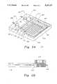
- FIG. 1is a exploded view of the present invention
- FIG. 2Ais a perspective view of the base plate
- FIG. 2Bis a sectional view of the base plate
- FIG. 3is a cut-away view of the valve
- FIG. 4Ais a perspective view of the gasket
- FIG. 4Bis a sectional view of the gasket
- FIG. 5Ais a plan view of the well plate
- FIG. 5Bis a sectional view of the well plate.
- the present inventionis an apparatus configured to sample media.
- One feature of the present inventionis a first vacuum member adapted to bring the media in contact with a filter membrane.
- a second feature of the present inventionis a second vacuum member adapted to provide the clamping force necessary to seal the apparatus so that the first vacuum member can properly bring the media in contact with the filter membrane.
- the vacuum clamping feature of the present inventionprovides several advantages heretofore unavailable in conventional media testing apparatus.
- One such advantagerelates to the resultant sample media on the filter membrane,
- the vacuum clamping featureprovides a more consistent clamping force than that of the screws and clamps used in conventional apparatus.
- a consistent clamping forceensures that each of the sample media will be properly placed on the filter membrane.
- a second advantagerelates to operation. More particularly, the vacuum clamping feature makes operation of the present invention significantly easier than conventional apparatus. Ease of operation leads to increased production output and efficiency.
- the apparatus 100generally comprises a filter membrane 110, a base plate 112, a first vacuum valve 114, a second vacuum valve 116, a gasket 118, a well plate 120, and a cover plate 122.
- the filter membrane 110is provided to receive and capture sample media.
- the filter membrane 110is well known in the art.
- filter membrane 110is made of either nylon or nitrocellulose.
- any type of filter membranecould potentially be used with the present invention.
- Such alternative filter membranesinclude, but are not limited to, polyvinylidene fluoride membranes, cellulose acetate membranes, and modified nylon membranes.
- the base plate 112is generally configured to provide the two independent vacuum features.
- the first vacuum featureoperates to bring the sample media contained in well plate 120 into contact with the filter membrane 110.
- the second vacuum featureoperates to clamp the filter membrane 110, base plate 112, gasket 118, and well plate 120 assembly together.
- the second vacuum featurereplaces the screw clamps found in conventional apparatus.
- the first vacuum valve 114is generally provided to regulate the first vacuum feature. As will be more fully described herein, the first vacuum valve 114 is configured to allow the user to control the rate at which the media samples are drawn into contact with the filter membrane 110. As shown by cover plate 122, the first vacuum valve 114 is rotatable to a first position where the vacuum valve 114 is in an "on" position 134 and a second position where the first vacuum valve 114 is in an "off" position 136. When the first vacuum valve 114 is in the "on" position 134, a vacuum is generated in the base plate 112 causing the sample media in the well plate 120 to be drawn into contact with the filter membrane 110.
- the second vacuum valve 116is generally provided to regulate the second vacuum feature. As will be more fully described herein, the second vacuum valve 116, allows the user to control the clamp force that holds the filter membrane 110, base plate 112, gasket 118, and well plate 120 assembly together. Application of the clamp force allows the apparatus 100 to be quickly assembled. Removal of the clamp force allows the apparatus 100 to be quickly disassembled. As also shown by the cover plate 122, the second vacuum valve 116 is rotatable to a first position where the second vacuum valve 116 is in an "on" position 130 and a second position where the second vacuum valve 116 is in a "release" position 132. When the second vacuum valve 116 is in the "on" position 130, a vacuum is generated in the base plate 112 causing the base plate 112/gasket 118/filter membrane 110/well plate 120 assembly to be securely held together.
- the gasket 118is generally provided to seal the apparatus 100 such that the first vacuum feature and the second vacuum feature can operate at optimum performance levels. As will be shown more fully herein, gasket 118 ensures that the necessary clamping force is maintained such that no leakage of vacuum occurs from the second vacuum feature during operation of the first vacuum feature. Prevention of vacuum leakage from the second vacuum feature during operation of the first vacuum feature is essential to ensuring that the sample media is properly disposed on the filter membrane 110. Failure to prevent vacuum leakage from the second vacuum feature may result in migration of sample media across the filter membrane 110.
- the well plate 120is generally provided to hold the sample media to be tested by the apparatus 100. As will be described more fully herein, well plate 120 may be configured in a conventional 96 well microtiter configuration thereby allowing multiple sample media to be tested.
- Base plate 112comprises a first Vacuum inlet 206 and a second vacuum inlet 208.
- First vacuum inlet 206 and second vacuum inlet 208enable an external vacuum source (not shown) to be connected to the apparatus 100.
- First vacuum inlet 206corresponds to first vacuum feature.
- Second vacuum inlet 208corresponds to the second vacuum feature.
- First vacuum inlet 206 and second vacuum inlet 208are mounted via holes (not shown) in the base plate 112 by conventional mounting means.
- first vacuum inlet 206 and second vacuum inlet 208are quick disconnect hose barb fittings.
- the only important criteriais that each of vacuum inlets 206, 208 be capable of mating; and with the conventional tubing which is typically connected to the external vacuum source.
- first vacuum inlet 206 and second vacuum inlet 208could be connected to the same vacuum source.
- a wide variety of vacuum sourcesmay be used with the apparatus 100.
- Base plate 112further comprises a first opening 210 and a first channel 212.
- First opening 210provides communication between the first vacuum inlet 206 and the first channel 212.
- First opening 210is configured to accept the first vacuum valve 114.
- rotation of the first vacuum valve 114causes the first vacuum inlet 206 to be in and/or out of registration with the first channel 212.
- the first channel 212extends into a reservoir area 250 (to be described).
- Base plate 112further comprises a second opening 214 and second channel 216.
- Second opening 214is in communication with the second vacuum inlet 208 and the second channel 216.
- Second opening 214is configured to accept the second vacuum valve 116.
- rotation of the second vacuum valve 116causes the second vacuum inlet 208 to be in and/or out of registration with the second channel 216.
- the second channel 216extends into a vacuum clamping area 255 (shown in FIG. 4A and to be described in conjunction therewith).
- the vacuum reservoir area 250is a recessed region within the base plate 112.
- the vacuum reservoir area 250acts as a receptacle wherein a vacuum is generated to draw the sample media from the well plate 120 in contact with the filter membrane 110.
- the reservoir area 250is sized so as to provide a proper vacuum area and to drain the sample media which passes through the filter membrane 110.
- the vacuum reservoir area 250may take a variety of configurations.
- the vacuum reservoir area 250has formed therein a plurality of channels 252 equidistantly arranged.
- a single channel 254connects the plurality of channels 252 to each other.
- Single channel 254is provided so as to connect the channels 252 together.
- the plurality of channels 252 that are formed in the reservoir area 250are in registration with the openings (to be described) in the gasket 118 and the wells (to be described) of the well plate 120.
- the base plate 112has further formed therein a plurality of islands 275. As will be discussed below, the islands 275 in combination with the gasket 118 form the vacuum clamping area 255.
- the vacuum clamping area 255is hereby defined as the area where the vacuum clamping means operates on the well plate 120.
- the islands 275are sized to closely receive the gasket 118.
- a gasket recess 270is formed within the base plate 112, such that the top portion of gasket 118 (to be described) is at substantially the same height with the islands 275 of the base plate 112.
- the base plate 112further comprises an opening 280 positioned at the top of one island 275. Opening 280 is in communication with the second channel 216. Opening 280 introduces the clamping vacuum to the top of the island 275.
- the well plate 120has formed a vacuum transfer channel (to be described) which allows the vacuum present at the opening 280 to uniformly disperse throughout the top of the remaining islands 275 and those portions of the gasket 118 that lie between the islands 275.
- the base plate 112may further comprise a pair of positioning pins 290.
- the positioning pins 290enable the well plate 120 to be accurately placed on top of the base plate 112, and gasket 118 when the apparatus 100 is assembled.
- first vacuum valve 114operates as a switch to turn on and off the sampling vacuum. In particularly, rotation of the first vacuum valve 114 causes the first vacuum inlet 206 to be in and out of registration with the first channel 212.
- First vacuum valve 114has an upper portion 302 and a lower portion 304.
- the lower portion 304fits closely into the opening 210 of the base plate 112. A close fit is required to minimize leakage of vacuum. However, the lower portion 304 should be allowed to rotate within the opening 210.
- first channel 306Formed in the lower portion 304 is a first channel 306 and a second channel 308.
- Channel 306has at one end a first opening 318 and at the second end a second opening 316.
- Channel 308extends completely through the center of the lower portion 304.
- Channel 308has at one end a first opening 310 and at the second end a second opening 312.
- the second opening 316 of first channel 306intersects with the second channel 308 thus allowing communication between the first channel 306 and the second channel 308.
- the lower portionis further designed such that when the openings 310 and 312 are in registration with the first vacuum inlet 206 and first channel 212 of the base plate 112, respectively, the external vacuum source (not shown) is in communication with the vacuum reservoir area 250, and thus is turned “on.” When the openings 310 and 312 are not in registration with the first vacuum inlet 206 and first channel 212 of the base plate 112, the sampling vacuum is turned “off.”
- the lower portionis further designed such that when the opening 318 is in registration with a third channel 235 of the base plate 112, the opening 310 is in registration with the first channel 212, thus providing communication between the ambient atmosphere and the vacuum reservoir area 250. This communication allows the user to pressurize the vacuum reservoir area 250.
- the first vacuum valve 114further has formed ridge 320.
- Ridge 320is configured such that it will rest on the surface of the cover plate 122. Ridge 320 ensures that the openings 310 and 312 will register with the vacuum inlet 206 and first channel 212 and that openings 316 and 318 will register with third channel 235 and first channel 212.
- the second vacuum valve 116is designed in a manner similar to that of first vacuum valve 114 described above.
- the second vacuum valve 116is designed such that rotation of the second vacuum valve 116 to a first (i.e., "on") position results in communication between second vacuum inlet 208 and second channel 216 of base plate 112, thereby providing a vacuum to the vacuum clamping area 255.
- Rotation of the second vacuum valve 116 to a second positionresults in communication between a fourth channel 237 and the second channel 216 of the base plate 112, thus allowing for pressurization of the vacuum clamping area 255.
- gasket 118is made out of a flexible material, such as silicon or the like. In order to perform repeated filtrations with the same gasket, its material composition must be resilient. However, gasket 118 can be made out of a variety of flexible and/or resilient materials.
- the gasket 118first comprises an inner section 402.
- Inner section 402has formed therein a plurality of wells 404.
- wells 404In the embodiment shown by FIG. 4, a standard 96 microtiter well configuration is depicted.
- the claimed inventionanticipates the use of any number of wells taking a variety of shapes and sizes.
- the gasket 118further comprises a circular ridge 420 (not shown in FIG. 4A) surrounding each well 404.
- Each circular ridge 420rises approximately 0.002 inches above the surface of each well 404.
- Each circular ridge 420ensures, upon assembly of apparatus 100, that an airtight seal is made with a corresponding well (to be described) of the well plate 120.
- the gasket 118further comprises a webbed section 406.
- Webbed section 406comprises a plurality of webs 414 and bridges 416. The webs 414 and bridges 416 are configured to mate With the islands 275 formed in the base plate 112 to thereby firmly secure the gasket 118 therein.
- the gasket 118further comprises a first border ridge 410 and a second border ridge 412.
- First border ridge 410surrounds the perimeter of the inner area 402.
- Second border ridge 412surrounds the perimeter of the webbed section 406.
- the first and second border ridges 410 and 412are about 0.002 inch in height and upon assembly, function to define a closed vacuum clamping area 255 that will not leak vacuum.
- the gasket 118further comprises a tab portion 418.
- Tab portion 418is provided to allow easy removal of the gasket 118 from the base plate 112.
- Tab portion 418is configured to mate with recess 272 of the base plate 112.
- Well plate 120first comprises a plurality of wells 502.
- the wells 502are configured in a standard 96 well microtiter configuration.
- well plate 120could have wells of a variety of configuration depending on the type of test to be run in the apparatus 100.
- the well plate 120further comprises a recessed vacuum channel 504 extending around the perimeter of the well 502 pattern. Upon assembly, the area at the periphery of the vacuum channel 504 would be in sealable contact with the ridges 410 and 412 of the gasket 118. As such, the vacuum channel 504 becomes the ceiling for the vacuum clamping area 255 and closes it.
- the well plate 120further comprises a pair of pin insets 506, 508 to facilitate the placement of the well plate 120 with the base plate 112. Upon assembly, the positioning pins 290 of the base plate 112 mate with the pin insets 506 and 508, respectively.
- the first vacuum valve 114is set to the "release” position and the second vacuum valve 116 is set to the "off” position. As such, operation of the apparatus 100 can now begin.
- the external vacuum sourceis assumed to be on.
- the gasket 118is first placed onto the base plate 112.
- the plurality of webs 414 and bridges 416mate with the corresponding islands 275 on the base plate.
- the filter membrane 110is placed on the inner section 402 of the gasket 118.
- the well plate 120is placed on the base plate 112 via mating pins 290 and insets 506 and 508.
- the wells 502 of the well plate 120are in substantial registration with the wells 404 of the gasket 118.
- the channels 252 of base plate 112are positioned directly under the wells 404 of the gasket 118.
- the apparatus 100is ready to be clamped into position.
- the second vacuum valve 116is rotated to the "on" position.
- the well plate 120is forced into contact with the upper surface of the islands 275 and the ridges 410 and 412 of the gasket 118.
- the gasket 118conforms with any irregularities found on the surface of well plate 120.
- the circular ridges surrounding the wells 502 of the gasket 118are also compressed, thereby providing complete separation between the individual wells 502 of the well plate 120 on the filter membrane 110. Complete isolation of the wells 502 on the membrane 110 eliminates bleeding or migration of sample media across the filter membrane 110.
- the vacuum clamping forcereaches maximum and the apparatus 100 is fully clamped.
- the ridges 410 and 412 of the gasket 118are in sealable contact with the well plate 120 and the vacuum clamping area 255 is fully enclosed by the islands 275, the ridges 410 and 412, and the vacuum channel 504 of the well plate 120.
- Sample mediamay be loaded into the wells 502 of the well plate 120. Thereafter, the filtration process is initiated by rotating the first vacuum valve 114 to the "on” position. Rotation of the first vacuum valve 114 to the "on” position causes a vacuum to come about in the vacuum reservoir area 250. As such, the sample media contained in the wells 502 of the well plate 120 are brought into contact with the filter membrane 110. Sample media that passes through the filter membrane 110 is discharged through the vacuum reservoir area 250 and out the channel 212 and first vacuum inlet 206.
- the userrotates the first vacuum valve 114 to the "off" position.
- external vacuum sourceis disengaged from the vacuum reservoir area 250 and moreover, the vacuum reservoir area 250 is in communication with the surrounding ambient environment. This pressurizes the vacuum reservoir area 250 thereby stopping the drainage of sample media from the wells 502 of the well plate 120.
- the userhas two options. First, the user can re-load the well plate 120 with additional and/or different sample media. Because the second vacuum valve 116 is still in the "on" position, the user can not remove the well plate 120 and as such any re-loading of sample media would have to be done with the well plate 120 still in place.
- the usermay want to remove the filter membrane 110 for further testing or the user may want to remove only the well plate 120 and replace it with an additional well plate 120 containing additional and/or different sample media to be tested with the existing sample media filtrate which is already present on the filter membrane 110.
- the userhas to rotate the second vacuum valve 116 to the "release” position. Rotation of the second vacuum valve 116 to the "release” position causes the external vacuum source to be disengaged from the vacuum clamping area 255 and the vacuum clamping area 255 to be in communication with the surrounding ambient environment. As such, this pressurizes the vacuum clamping area 255 thereby releasing the clamping force holding the apparatus 100 together.
- the well plate 120can be removed and replaced with another well plate 120 without removing the filter membrane 110.
- the usercan remove the well plate 120 and the filter membrane 110.
- the filter membrane 110can then be further tested as desired.
- the gasket 118can be removed by lifting up the tab 418 on gasket 118.
- the gasket 118can then be cleaned and replaced on the base plate 112 for use in the next test.
- a different gasket 118can be placed thereon.
- the present inventioncan draw the sample media into contact with the filter membrane in an uncontaminated manner.
- the vacuum clamping feature of the present inventionacts to isolate each well pattern on the filter membrane thereby eliminating sample media migration or so called bleeding that occurs in conventional apparatus.
- the apparatus of the present inventioncan be quickly assembled and disassembled thus increasing test production output and efficiency.
- Such modifications and/or alternative embodimentsmay include, but are not limited to, an additional channel formed in the well plate 120 so as to allow the space surrounding the annular ridge 420 of each well 404 in gasket 118 to be in communication with the ambient environment. This would guard against evacuation of this area in the event of an imperfect performance of the first border ridge 410 once the vacuum clamp is applied and in effect. Vacuum in this area would increase the likelihood of cross-well migration of samples.
Landscapes
- Health & Medical Sciences (AREA)
- Chemical & Material Sciences (AREA)
- Immunology (AREA)
- Life Sciences & Earth Sciences (AREA)
- Engineering & Computer Science (AREA)
- Hematology (AREA)
- Analytical Chemistry (AREA)
- General Health & Medical Sciences (AREA)
- Urology & Nephrology (AREA)
- Chemical Kinetics & Catalysis (AREA)
- Biomedical Technology (AREA)
- Molecular Biology (AREA)
- Cell Biology (AREA)
- Microbiology (AREA)
- Biotechnology (AREA)
- Clinical Laboratory Science (AREA)
- Food Science & Technology (AREA)
- Medicinal Chemistry (AREA)
- Physics & Mathematics (AREA)
- Biochemistry (AREA)
- General Physics & Mathematics (AREA)
- Pathology (AREA)
- Water Supply & Treatment (AREA)
- Sampling And Sample Adjustment (AREA)
Abstract
Description
Claims (17)
Priority Applications (1)
| Application Number | Priority Date | Filing Date | Title |
|---|---|---|---|
| US07/924,795US5227137A (en) | 1991-04-04 | 1992-08-06 | Vacuum clamped multi-sample filtration apparatus |
Applications Claiming Priority (2)
| Application Number | Priority Date | Filing Date | Title |
|---|---|---|---|
| US68054491A | 1991-04-04 | 1991-04-04 | |
| US07/924,795US5227137A (en) | 1991-04-04 | 1992-08-06 | Vacuum clamped multi-sample filtration apparatus |
Related Parent Applications (1)
| Application Number | Title | Priority Date | Filing Date |
|---|---|---|---|
| US68054491AContinuation | 1991-04-04 | 1991-04-04 |
Publications (1)
| Publication Number | Publication Date |
|---|---|
| US5227137Atrue US5227137A (en) | 1993-07-13 |
Family
ID=27102481
Family Applications (1)
| Application Number | Title | Priority Date | Filing Date |
|---|---|---|---|
| US07/924,795Expired - LifetimeUS5227137A (en) | 1991-04-04 | 1992-08-06 | Vacuum clamped multi-sample filtration apparatus |
Country Status (1)
| Country | Link |
|---|---|
| US (1) | US5227137A (en) |
Cited By (50)
| Publication number | Priority date | Publication date | Assignee | Title |
|---|---|---|---|---|
| US5346142A (en)* | 1993-02-05 | 1994-09-13 | Premier Medical Technology Inc. | Continuous shredding apparatus for medical waste material and method for use thereof |
| US5543114A (en)* | 1994-01-31 | 1996-08-06 | Dudek; Peter P. | Unitary biological specimen processing apparatus |
| US5604130A (en)* | 1995-05-31 | 1997-02-18 | Chiron Corporation | Releasable multiwell plate cover |
| US5603899A (en)* | 1995-04-12 | 1997-02-18 | Pharmacia Biotech, Inc. | Multiple column chromatography assembly |
| WO1998014277A1 (en)* | 1996-10-04 | 1998-04-09 | Whatman, Inc. | Device and method for simultaneous multiple chemical syntheses |
| WO1998014782A1 (en)* | 1996-10-02 | 1998-04-09 | Safety Associates, Inc. | Methods and apparatus for determining specific analytes in foods and other complex matrices |
| US5888830A (en)* | 1995-09-22 | 1999-03-30 | Berlex Laboratories, Inc. | Apparatus and process for multiple chemical reactions |
| USD414272S (en) | 1994-07-06 | 1999-09-21 | Biomerieux Vitek, Inc. | Biochemical card for use in automated microbial machines |
| US6133045A (en)* | 1998-02-27 | 2000-10-17 | Hamilton Company | Automated sample treatment system: apparatus and method |
| US6159368A (en)* | 1998-10-29 | 2000-12-12 | The Perkin-Elmer Corporation | Multi-well microfiltration apparatus |
| WO2001030490A1 (en)* | 1999-10-22 | 2001-05-03 | Aclara Biosciences, Inc. | Sealing for microfluidic devices |
| US6303389B1 (en) | 1997-06-27 | 2001-10-16 | Immunetics | Rapid flow-through binding assay apparatus and method therefor |
| US6315957B1 (en)* | 1999-01-15 | 2001-11-13 | Pharmacopeia, Inc. | Article comprising a filter pocket-plate |
| US20020037237A1 (en)* | 2000-06-15 | 2002-03-28 | Mainquist James K. | Automated precision object holder and method of using same |
| US6379625B1 (en)* | 1999-12-23 | 2002-04-30 | Peter Zuk, Jr. | Apparatus comprising a disposable device and reusable instrument for synthesizing chemical compounds, and for testing chemical compounds for solubility |
| US6416719B1 (en)* | 2001-01-19 | 2002-07-09 | Gilson, Inc. | Plate locator for precision liquid handler |
| US6419827B1 (en) | 1998-10-29 | 2002-07-16 | Applera Corporation | Purification apparatus and method |
| WO2002058849A1 (en)* | 2001-01-23 | 2002-08-01 | Varian, Inc. | Multi-well filtration apparatus |
| US20020110925A1 (en)* | 2000-06-13 | 2002-08-15 | Symyx Technologies, Inc. | Apparatus and method for testing compositions in contact with a porous medium |
| US6464942B2 (en)* | 1997-10-10 | 2002-10-15 | Ciphergen Biosystems, Inc. | Plate alignment and sample transfer indicia for a multiwell multiplate stack and method for processing biological/chemical samples using the same |
| US20020150505A1 (en)* | 1998-10-29 | 2002-10-17 | Reed Mark T. | Manually-operable multi-well microfiltration apparatus and method |
| US20030033394A1 (en)* | 2001-03-21 | 2003-02-13 | Stine John A. | Access and routing protocol for ad hoc network using synchronous collision resolution and node state dissemination |
| US20030124715A1 (en)* | 1999-07-16 | 2003-07-03 | Tortorella Micky D. | Novel filtrate plate device and reversible-well plate device |
| US6589790B1 (en) | 1997-04-15 | 2003-07-08 | Bio Merieux | Method and device for filling an analysis card with a liquid medium |
| US20030143124A1 (en)* | 2002-01-31 | 2003-07-31 | Roberts Roger Q. | Unidirectional flow control sealing matt |
| FR2839458A1 (en)* | 2002-05-07 | 2003-11-14 | Univ Lille Sciences Tech | SOLID PHASE EXTRACTION PROCESS, PARTICULARLY FOR THE ANALYSIS OF BIOLOGICAL SAMPLES AND DEVICE FOR CARRYING OUT THE PROCESS |
| US6675974B2 (en) | 1996-05-06 | 2004-01-13 | Trek Diagnostic Systems Inc. | Device for handling specimens |
| US20040033619A1 (en)* | 1998-10-29 | 2004-02-19 | Weinfield Todd A. | Sample tray heater module |
| US20040057877A1 (en)* | 2000-12-20 | 2004-03-25 | Markus Rarbach | Solid phase substrates for structured reaction substrates |
| US20040157343A1 (en)* | 2003-02-06 | 2004-08-12 | Applera Corporation | Devices and methods for biological sample preparation |
| US20040177670A1 (en)* | 2001-01-24 | 2004-09-16 | Gilson, Inc. | Probe tip alignment for precision liquid handler |
| EP0868504A4 (en)* | 1995-11-28 | 2004-12-08 | Ixsys Inc | Methods for the efficient isolation of periplasmic space fractions from multiple samples of bacteria |
| US20040265186A1 (en)* | 2003-06-24 | 2004-12-30 | Phillip Clark | Multifunctional vacuum manifold |
| US20050069462A1 (en)* | 2003-09-30 | 2005-03-31 | International Business Machines Corporation | Microfluidics Packaging |
| US20050069949A1 (en)* | 2003-09-30 | 2005-03-31 | International Business Machines Corporation | Microfabricated Fluidic Structures |
| US6899848B1 (en) | 2001-02-27 | 2005-05-31 | Hamilton Company | Automated sample treatment system: apparatus and method |
| US6908594B1 (en) | 1999-10-22 | 2005-06-21 | Aclara Biosciences, Inc. | Efficient microfluidic sealing |
| US20050173062A1 (en)* | 2003-12-12 | 2005-08-11 | Becton Dickinson And Company | Membrane attachment process |
| US20070144959A1 (en)* | 2005-09-02 | 2007-06-28 | Zuk Peter Jr | Systems, apparatus and methods for vacuum filtration |
| US20080253927A1 (en)* | 2000-10-13 | 2008-10-16 | Irm Llc | High throughput processing system and method of using |
| US20080290040A1 (en)* | 2007-05-23 | 2008-11-27 | Nypro Inc. | Methods and Apparatus for Foam Control in a Vacuum Filtration System |
| US20090026154A1 (en)* | 2007-07-26 | 2009-01-29 | Nypro Inc. | Methods and Apparatus for Supporting a Vacuum Filtration Device |
| US20090026153A1 (en)* | 2007-07-26 | 2009-01-29 | Nypro Inc. | Method and apparatus for filtrate storage handling |
| US20090171251A1 (en)* | 2007-12-27 | 2009-07-02 | Andrey Rybyanets | Ultrasound treatment of adipose tissue with vacuum feature |
| US20100181251A1 (en)* | 2007-06-25 | 2010-07-22 | Benno Alspektor | Bidirectional Transfer of an Aliquot of Fluid Between Compartments |
| DE102009036695B3 (en)* | 2009-08-07 | 2011-04-07 | Hp Medizintechnik Gmbh | Insert for a well in a multiwell plate, comprises a base body, whose external contour is partially adapted at the internal contour of the well in such a way that the insert inserted into the well has a defined measuring volume |
| US20160139090A1 (en)* | 2013-06-19 | 2016-05-19 | Universiteit Leiden | Method and device for receiving a droplet |
| US11179677B2 (en) | 2015-06-30 | 2021-11-23 | Emd Millipore Corporation | Sealing case for filter cassette |
| US20230204479A1 (en)* | 2021-12-29 | 2023-06-29 | Andrew Alliance S.A. | Sample extraction system and method |
| US11852579B2 (en)* | 2020-06-16 | 2023-12-26 | Columbia Insurance Company | Devices, systems, and methods for testing surface covering materials |
Citations (24)
| Publication number | Priority date | Publication date | Assignee | Title |
|---|---|---|---|---|
| US3956125A (en)* | 1973-08-17 | 1976-05-11 | Strutt & Farrands Ltd. | Filtration apparatus |
| US4090850A (en)* | 1976-11-01 | 1978-05-23 | E. R. Squibb & Sons, Inc. | Apparatus for use in radioimmunoassays |
| US4167875A (en)* | 1976-08-05 | 1979-09-18 | Meakin John C | Filtration method and apparatus |
| US4219530A (en)* | 1978-01-27 | 1980-08-26 | Brinkmann Instruments, Inc. | Apparatus for analyzing biological specimens |
| US4427415A (en)* | 1979-01-05 | 1984-01-24 | Cleveland Patrick H | Manifold vacuum biochemical test method and device |
| US4493815A (en)* | 1983-07-28 | 1985-01-15 | Bio-Rad Laboratories, Inc. | Supporting and filtering biochemical test plate assembly |
| US4704255A (en)* | 1983-07-15 | 1987-11-03 | Pandex Laboratories, Inc. | Assay cartridge |
| US4726932A (en)* | 1983-10-06 | 1988-02-23 | Contraves Ag | Dosing and mixing apparatus for fluid media |
| US4777021A (en)* | 1986-04-25 | 1988-10-11 | Richard K. Wertz | Manifold vacuum device for biochemical and immunological uses |
| US4787988A (en)* | 1987-02-20 | 1988-11-29 | Biomedical Research And Development Laboratories, Inc. | Cell harvester |
| US4797259A (en)* | 1986-12-15 | 1989-01-10 | Pall Corporation | Well-type diagnostic plate device |
| US4822741A (en)* | 1987-05-04 | 1989-04-18 | Banes Albert J | Biocompatible polyorganosiloxane composition for cell culture apparatus |
| US4828801A (en)* | 1985-07-02 | 1989-05-09 | Centre National De La Recherche Scientifique | Device for detecting on a nitrocellulose sheet the presence of macromolecular complexes, such as antigens/antibodies |
| US4834946A (en)* | 1987-02-05 | 1989-05-30 | Levin Andrew E | Apparatus for blot screening numerous, small volume, antibody solutions |
| US4839292A (en)* | 1987-09-11 | 1989-06-13 | Cremonese Joseph G | Cell culture flask utilizing a membrane barrier |
| US4846970A (en)* | 1987-06-22 | 1989-07-11 | Osmonics, Inc. | Cross-flow filtration membrane test unit |
| US4859419A (en)* | 1987-02-27 | 1989-08-22 | American Bionetics, Inc. | Diagnostic manifold apparatus |
| US4874691A (en)* | 1987-10-16 | 1989-10-17 | Quadra Logic Technologies Inc. | Membrane-supported immunoassays |
| US4895706A (en)* | 1986-10-28 | 1990-01-23 | Costar Corporation | Multi-well filter strip and composite assemblies |
| US4902481A (en)* | 1987-12-11 | 1990-02-20 | Millipore Corporation | Multi-well filtration test apparatus |
| US4908319A (en)* | 1988-03-16 | 1990-03-13 | Smyczek Peter J | Laboratory apparatus |
| US4927604A (en)* | 1988-12-05 | 1990-05-22 | Costar Corporation | Multiwell filter plate vacuum manifold assembly |
| US4948564A (en)* | 1986-10-28 | 1990-08-14 | Costar Corporation | Multi-well filter strip and composite assemblies |
| US4978507A (en)* | 1988-05-31 | 1990-12-18 | Levin Andrew E | Fluid flow manifold for blot type screening apparatus |
- 1992
- 1992-08-06USUS07/924,795patent/US5227137A/ennot_activeExpired - Lifetime
Patent Citations (25)
| Publication number | Priority date | Publication date | Assignee | Title |
|---|---|---|---|---|
| US3956125A (en)* | 1973-08-17 | 1976-05-11 | Strutt & Farrands Ltd. | Filtration apparatus |
| US4167875A (en)* | 1976-08-05 | 1979-09-18 | Meakin John C | Filtration method and apparatus |
| US4090850A (en)* | 1976-11-01 | 1978-05-23 | E. R. Squibb & Sons, Inc. | Apparatus for use in radioimmunoassays |
| US4219530A (en)* | 1978-01-27 | 1980-08-26 | Brinkmann Instruments, Inc. | Apparatus for analyzing biological specimens |
| US4427415A (en)* | 1979-01-05 | 1984-01-24 | Cleveland Patrick H | Manifold vacuum biochemical test method and device |
| US4704255A (en)* | 1983-07-15 | 1987-11-03 | Pandex Laboratories, Inc. | Assay cartridge |
| US4493815A (en)* | 1983-07-28 | 1985-01-15 | Bio-Rad Laboratories, Inc. | Supporting and filtering biochemical test plate assembly |
| US4726932A (en)* | 1983-10-06 | 1988-02-23 | Contraves Ag | Dosing and mixing apparatus for fluid media |
| US4828801A (en)* | 1985-07-02 | 1989-05-09 | Centre National De La Recherche Scientifique | Device for detecting on a nitrocellulose sheet the presence of macromolecular complexes, such as antigens/antibodies |
| US4777021A (en)* | 1986-04-25 | 1988-10-11 | Richard K. Wertz | Manifold vacuum device for biochemical and immunological uses |
| US4948564A (en)* | 1986-10-28 | 1990-08-14 | Costar Corporation | Multi-well filter strip and composite assemblies |
| US4895706A (en)* | 1986-10-28 | 1990-01-23 | Costar Corporation | Multi-well filter strip and composite assemblies |
| US4797259A (en)* | 1986-12-15 | 1989-01-10 | Pall Corporation | Well-type diagnostic plate device |
| US4834946A (en)* | 1987-02-05 | 1989-05-30 | Levin Andrew E | Apparatus for blot screening numerous, small volume, antibody solutions |
| US4787988A (en)* | 1987-02-20 | 1988-11-29 | Biomedical Research And Development Laboratories, Inc. | Cell harvester |
| US4859419A (en)* | 1987-02-27 | 1989-08-22 | American Bionetics, Inc. | Diagnostic manifold apparatus |
| US4822741A (en)* | 1987-05-04 | 1989-04-18 | Banes Albert J | Biocompatible polyorganosiloxane composition for cell culture apparatus |
| US4846970A (en)* | 1987-06-22 | 1989-07-11 | Osmonics, Inc. | Cross-flow filtration membrane test unit |
| US4839292A (en)* | 1987-09-11 | 1989-06-13 | Cremonese Joseph G | Cell culture flask utilizing a membrane barrier |
| US4839292B1 (en)* | 1987-09-11 | 1994-09-13 | Joseph G Cremonese | Cell culture flask utilizing membrane barrier |
| US4874691A (en)* | 1987-10-16 | 1989-10-17 | Quadra Logic Technologies Inc. | Membrane-supported immunoassays |
| US4902481A (en)* | 1987-12-11 | 1990-02-20 | Millipore Corporation | Multi-well filtration test apparatus |
| US4908319A (en)* | 1988-03-16 | 1990-03-13 | Smyczek Peter J | Laboratory apparatus |
| US4978507A (en)* | 1988-05-31 | 1990-12-18 | Levin Andrew E | Fluid flow manifold for blot type screening apparatus |
| US4927604A (en)* | 1988-12-05 | 1990-05-22 | Costar Corporation | Multiwell filter plate vacuum manifold assembly |
Cited By (88)
| Publication number | Priority date | Publication date | Assignee | Title |
|---|---|---|---|---|
| US5346142A (en)* | 1993-02-05 | 1994-09-13 | Premier Medical Technology Inc. | Continuous shredding apparatus for medical waste material and method for use thereof |
| US5543114A (en)* | 1994-01-31 | 1996-08-06 | Dudek; Peter P. | Unitary biological specimen processing apparatus |
| USD414272S (en) | 1994-07-06 | 1999-09-21 | Biomerieux Vitek, Inc. | Biochemical card for use in automated microbial machines |
| US5603899A (en)* | 1995-04-12 | 1997-02-18 | Pharmacia Biotech, Inc. | Multiple column chromatography assembly |
| US5604130A (en)* | 1995-05-31 | 1997-02-18 | Chiron Corporation | Releasable multiwell plate cover |
| US5888830A (en)* | 1995-09-22 | 1999-03-30 | Berlex Laboratories, Inc. | Apparatus and process for multiple chemical reactions |
| US6274091B1 (en) | 1995-09-22 | 2001-08-14 | Berlex Laboratories, Inc. | Apparatus and process for multiple chemical reactions |
| EP0868504A4 (en)* | 1995-11-28 | 2004-12-08 | Ixsys Inc | Methods for the efficient isolation of periplasmic space fractions from multiple samples of bacteria |
| US6675974B2 (en) | 1996-05-06 | 2004-01-13 | Trek Diagnostic Systems Inc. | Device for handling specimens |
| WO1998014782A1 (en)* | 1996-10-02 | 1998-04-09 | Safety Associates, Inc. | Methods and apparatus for determining specific analytes in foods and other complex matrices |
| WO1998014277A1 (en)* | 1996-10-04 | 1998-04-09 | Whatman, Inc. | Device and method for simultaneous multiple chemical syntheses |
| US6589790B1 (en) | 1997-04-15 | 2003-07-08 | Bio Merieux | Method and device for filling an analysis card with a liquid medium |
| US6303389B1 (en) | 1997-06-27 | 2001-10-16 | Immunetics | Rapid flow-through binding assay apparatus and method therefor |
| US6464942B2 (en)* | 1997-10-10 | 2002-10-15 | Ciphergen Biosystems, Inc. | Plate alignment and sample transfer indicia for a multiwell multiplate stack and method for processing biological/chemical samples using the same |
| US7273759B2 (en) | 1997-10-10 | 2007-09-25 | Pall Corporation | Plate alignment and sample transfer indicia for a multiwell multiplate stack and method for processing biological/chemical samples using the same |
| US20030008412A1 (en)* | 1997-10-10 | 2003-01-09 | Ciphergen Biosystems, Inc. | Plate alignment and sample transfer indicia for a multiwell multiplate stack and method for processing biological/chemical samples using the same |
| US6133045A (en)* | 1998-02-27 | 2000-10-17 | Hamilton Company | Automated sample treatment system: apparatus and method |
| US6419827B1 (en) | 1998-10-29 | 2002-07-16 | Applera Corporation | Purification apparatus and method |
| US6896849B2 (en) | 1998-10-29 | 2005-05-24 | Applera Corporation | Manually-operable multi-well microfiltration apparatus and method |
| US7019267B2 (en) | 1998-10-29 | 2006-03-28 | Applera Corporation | Sample tray heater module |
| US20050194371A1 (en)* | 1998-10-29 | 2005-09-08 | Applera Corporation | Sample tray heater module |
| US20040033619A1 (en)* | 1998-10-29 | 2004-02-19 | Weinfield Todd A. | Sample tray heater module |
| US6451261B1 (en) | 1998-10-29 | 2002-09-17 | Applera Corporation | Multi-well microfiltration apparatus |
| US20060191893A1 (en)* | 1998-10-29 | 2006-08-31 | Applera Corporation | Manually-operable multi-well microfiltration apparatus and method |
| US20020150505A1 (en)* | 1998-10-29 | 2002-10-17 | Reed Mark T. | Manually-operable multi-well microfiltration apparatus and method |
| US6906292B2 (en) | 1998-10-29 | 2005-06-14 | Applera Corporation | Sample tray heater module |
| US7452510B2 (en) | 1998-10-29 | 2008-11-18 | Applied Biosystems Inc. | Manually-operable multi-well microfiltration apparatus and method |
| US6506343B1 (en) | 1998-10-29 | 2003-01-14 | Applera Corporation | Multi-well microfiltration apparatus and method for avoiding cross-contamination |
| US6783732B2 (en) | 1998-10-29 | 2004-08-31 | Applera Corporation | Apparatus and method for avoiding cross-contamination due to pendent drops of fluid hanging from discharge conduits |
| US6159368A (en)* | 1998-10-29 | 2000-12-12 | The Perkin-Elmer Corporation | Multi-well microfiltration apparatus |
| US6338802B1 (en) | 1998-10-29 | 2002-01-15 | Pe Corporation (Ny) | Multi-well microfiltration apparatus |
| US20030215956A1 (en)* | 1998-10-29 | 2003-11-20 | Reed Mark T. | Multi-well microfiltration apparatus |
| US6315957B1 (en)* | 1999-01-15 | 2001-11-13 | Pharmacopeia, Inc. | Article comprising a filter pocket-plate |
| US6635430B1 (en)* | 1999-07-16 | 2003-10-21 | Dupont Pharmaceuticals Company | Filtrate plate device and reversible-well plate device |
| US6887671B2 (en) | 1999-07-16 | 2005-05-03 | Depont Pharmaceuticals Company | Filtrate plate device and reversible-well plate device |
| US20030124715A1 (en)* | 1999-07-16 | 2003-07-03 | Tortorella Micky D. | Novel filtrate plate device and reversible-well plate device |
| WO2001030490A1 (en)* | 1999-10-22 | 2001-05-03 | Aclara Biosciences, Inc. | Sealing for microfluidic devices |
| US6908594B1 (en) | 1999-10-22 | 2005-06-21 | Aclara Biosciences, Inc. | Efficient microfluidic sealing |
| US6379625B1 (en)* | 1999-12-23 | 2002-04-30 | Peter Zuk, Jr. | Apparatus comprising a disposable device and reusable instrument for synthesizing chemical compounds, and for testing chemical compounds for solubility |
| US6878344B2 (en)* | 2000-06-13 | 2005-04-12 | Symyx Technologies, Inc. | Apparatus for testing compositions in contact with a porous medium |
| US20020110925A1 (en)* | 2000-06-13 | 2002-08-15 | Symyx Technologies, Inc. | Apparatus and method for testing compositions in contact with a porous medium |
| US20020037237A1 (en)* | 2000-06-15 | 2002-03-28 | Mainquist James K. | Automated precision object holder and method of using same |
| US20080253927A1 (en)* | 2000-10-13 | 2008-10-16 | Irm Llc | High throughput processing system and method of using |
| EP1344061B1 (en)* | 2000-12-20 | 2008-04-02 | Direvo Biotech AG | Solid phase substrates for structured reaction substrates |
| US20040057877A1 (en)* | 2000-12-20 | 2004-03-25 | Markus Rarbach | Solid phase substrates for structured reaction substrates |
| CN1326690C (en)* | 2001-01-19 | 2007-07-18 | 吉尔森公司 | Sample Plate Positioner for Precision Liquid Handlers |
| US6416719B1 (en)* | 2001-01-19 | 2002-07-09 | Gilson, Inc. | Plate locator for precision liquid handler |
| WO2002057077A1 (en)* | 2001-01-19 | 2002-07-25 | Gilson, Inc. | Plate locator for precision liquid handler |
| WO2002058849A1 (en)* | 2001-01-23 | 2002-08-01 | Varian, Inc. | Multi-well filtration apparatus |
| US6491873B2 (en)* | 2001-01-23 | 2002-12-10 | Varian, Inc. | Multi-well filtration apparatus |
| US20040177670A1 (en)* | 2001-01-24 | 2004-09-16 | Gilson, Inc. | Probe tip alignment for precision liquid handler |
| US6901819B2 (en) | 2001-01-24 | 2005-06-07 | Gilson, Inc. | Probe tip alignment for precision liquid handler |
| US6899848B1 (en) | 2001-02-27 | 2005-05-31 | Hamilton Company | Automated sample treatment system: apparatus and method |
| US20030033394A1 (en)* | 2001-03-21 | 2003-02-13 | Stine John A. | Access and routing protocol for ad hoc network using synchronous collision resolution and node state dissemination |
| US20030143124A1 (en)* | 2002-01-31 | 2003-07-31 | Roberts Roger Q. | Unidirectional flow control sealing matt |
| WO2003064041A1 (en)* | 2002-01-31 | 2003-08-07 | Varian, Inc. | Unidirectional flow control sealing matt for well plate |
| AU2003210528B2 (en)* | 2002-01-31 | 2007-12-06 | Agilent Technologies, Inc. | Unidirectional flow control sealing matt for well plate |
| FR2839458A1 (en)* | 2002-05-07 | 2003-11-14 | Univ Lille Sciences Tech | SOLID PHASE EXTRACTION PROCESS, PARTICULARLY FOR THE ANALYSIS OF BIOLOGICAL SAMPLES AND DEVICE FOR CARRYING OUT THE PROCESS |
| US20040157343A1 (en)* | 2003-02-06 | 2004-08-12 | Applera Corporation | Devices and methods for biological sample preparation |
| US7824623B2 (en) | 2003-06-24 | 2010-11-02 | Millipore Corporation | Multifunctional vacuum manifold |
| US8007743B2 (en) | 2003-06-24 | 2011-08-30 | Millipore Corporation | Multifunctional vacuum manifold |
| US20040265186A1 (en)* | 2003-06-24 | 2004-12-30 | Phillip Clark | Multifunctional vacuum manifold |
| US20050069462A1 (en)* | 2003-09-30 | 2005-03-31 | International Business Machines Corporation | Microfluidics Packaging |
| US20050069949A1 (en)* | 2003-09-30 | 2005-03-31 | International Business Machines Corporation | Microfabricated Fluidic Structures |
| US20050173062A1 (en)* | 2003-12-12 | 2005-08-11 | Becton Dickinson And Company | Membrane attachment process |
| US7404873B2 (en) | 2003-12-12 | 2008-07-29 | Becton, Dickinson And Company | Membrane attachment process |
| US7798333B2 (en) | 2005-09-02 | 2010-09-21 | Roush Life Sciences, Llc | Systems, apparatus and methods for vacuum filtration |
| US20070144959A1 (en)* | 2005-09-02 | 2007-06-28 | Zuk Peter Jr | Systems, apparatus and methods for vacuum filtration |
| US20080290040A1 (en)* | 2007-05-23 | 2008-11-27 | Nypro Inc. | Methods and Apparatus for Foam Control in a Vacuum Filtration System |
| US8158009B2 (en) | 2007-05-23 | 2012-04-17 | Roush Life Sciences, Llc | Methods and apparatus for foam control in a vacuum filtration system |
| US8506813B2 (en) | 2007-06-25 | 2013-08-13 | Beno Alspektor | Bidirectional transfer of an aliquot of fluid between compartments |
| US20100181251A1 (en)* | 2007-06-25 | 2010-07-22 | Benno Alspektor | Bidirectional Transfer of an Aliquot of Fluid Between Compartments |
| US20090026153A1 (en)* | 2007-07-26 | 2009-01-29 | Nypro Inc. | Method and apparatus for filtrate storage handling |
| US20090026126A1 (en)* | 2007-07-26 | 2009-01-29 | Nypro Inc. | Vacuum Base and Related Methods and Apparatus for Vacuum Filtration |
| US8235221B2 (en) | 2007-07-26 | 2012-08-07 | Roush Life Sciences, Llc | Methods for vacuum filtration |
| US8231012B2 (en) | 2007-07-26 | 2012-07-31 | Roush Life Sciences, Llc | Filtrate storage system |
| US8157104B2 (en) | 2007-07-26 | 2012-04-17 | Roush Life Sciences, Llc | Apparatus for supporting a vacuum filtration device |
| US20090026154A1 (en)* | 2007-07-26 | 2009-01-29 | Nypro Inc. | Methods and Apparatus for Supporting a Vacuum Filtration Device |
| US20090171251A1 (en)* | 2007-12-27 | 2009-07-02 | Andrey Rybyanets | Ultrasound treatment of adipose tissue with vacuum feature |
| GB2469010B (en)* | 2008-02-07 | 2013-01-09 | Ultrashape Ltd | Ultrasound treatment of adipose tissue with vacuum feature |
| GB2469010A (en)* | 2008-02-07 | 2010-09-29 | Ultrashape Ltd | Ultrasound treatment of adipose tissue with vacuum feature |
| WO2009098606A3 (en)* | 2008-02-07 | 2009-12-23 | Ultrashape Ltd. | Ultrasound treatment of adipose tissue with vacuum feature |
| DE102009036695B3 (en)* | 2009-08-07 | 2011-04-07 | Hp Medizintechnik Gmbh | Insert for a well in a multiwell plate, comprises a base body, whose external contour is partially adapted at the internal contour of the well in such a way that the insert inserted into the well has a defined measuring volume |
| US20160139090A1 (en)* | 2013-06-19 | 2016-05-19 | Universiteit Leiden | Method and device for receiving a droplet |
| US10006889B2 (en)* | 2013-06-19 | 2018-06-26 | Universiteit Leiden | Method and device for receiving a droplet |
| US11179677B2 (en) | 2015-06-30 | 2021-11-23 | Emd Millipore Corporation | Sealing case for filter cassette |
| US11852579B2 (en)* | 2020-06-16 | 2023-12-26 | Columbia Insurance Company | Devices, systems, and methods for testing surface covering materials |
| US20230204479A1 (en)* | 2021-12-29 | 2023-06-29 | Andrew Alliance S.A. | Sample extraction system and method |
Similar Documents
| Publication | Publication Date | Title |
|---|---|---|
| US5227137A (en) | Vacuum clamped multi-sample filtration apparatus | |
| US5108603A (en) | Self-contained vacuum clamped multi-sample media filtration apparatus and method | |
| US5141719A (en) | Multi-sample filtration plate assembly | |
| US4493815A (en) | Supporting and filtering biochemical test plate assembly | |
| EP1383604B1 (en) | Unidirectional flow control sealing matt for well plate | |
| US4948564A (en) | Multi-well filter strip and composite assemblies | |
| US4895706A (en) | Multi-well filter strip and composite assemblies | |
| US5205989A (en) | Multi-well filtration apparatus | |
| US5342581A (en) | Apparatus for preventing cross-contamination of multi-well test plates | |
| US4927604A (en) | Multiwell filter plate vacuum manifold assembly | |
| EP0227802A1 (en) | Multiwell test plate | |
| AU2003210528A1 (en) | Unidirectional flow control sealing matt for well plate | |
| CN111065446B (en) | Filter assembly and method for microbiological testing | |
| JPH02187110A (en) | Micro-filtration apparatus and its method | |
| US5409832A (en) | Membrane holder for use in an assay device | |
| US11731083B2 (en) | Filtration assembly and method for microbiological testing | |
| JPH0585867B2 (en) | ||
| JP4794582B2 (en) | Multifunctional vacuum manifold | |
| EP0871544A1 (en) | Multiple sample filtration device | |
| WO1992017261A1 (en) | A vacuum clamped multi-sample filtration apparatus and method | |
| EP0075405A1 (en) | Re-usable filter units with recoverable filter membranes | |
| EP0438595A1 (en) | Jig and device for filtration |
Legal Events
| Date | Code | Title | Description |
|---|---|---|---|
| STCF | Information on status: patent grant | Free format text:PATENTED CASE | |
| FPAY | Fee payment | Year of fee payment:4 | |
| FPAY | Fee payment | Year of fee payment:8 | |
| AS | Assignment | Owner name:INVITROGEN CORPORATION, CALIFORNIA Free format text:MERGER;ASSIGNOR:LIFE TECHNOLOGIES, INC.;REEL/FRAME:013774/0942 Effective date:20000913 Owner name:LIFE TECHNOLOGIES, INC., MARYLAND Free format text:ASSIGNMENT OF ASSIGNORS INTEREST;ASSIGNOR:NICHOLSON PRECISION INSTRUMENTS, INC.;REEL/FRAME:013774/0926 Effective date:19910429 | |
| FPAY | Fee payment | Year of fee payment:12 | |
| AS | Assignment | Owner name:BANK OF AMERICA, N.A., AS COLLATERAL AGENT, WASHIN Free format text:SECURITY AGREEMENT;ASSIGNOR:LIFE TECHNOLOGIES CORPORATION;REEL/FRAME:021975/0467 Effective date:20081121 Owner name:BANK OF AMERICA, N.A., AS COLLATERAL AGENT,WASHING Free format text:SECURITY AGREEMENT;ASSIGNOR:LIFE TECHNOLOGIES CORPORATION;REEL/FRAME:021975/0467 Effective date:20081121 | |
| AS | Assignment | Owner name:LIFE TECHNOLOGIES CORPORATION,CALIFORNIA Free format text:MERGER;ASSIGNOR:INVITROGEN CORPORATION;REEL/FRAME:023882/0551 Effective date:20081121 Owner name:LIFE TECHNOLOGIES CORPORATION, CALIFORNIA Free format text:MERGER;ASSIGNOR:INVITROGEN CORPORATION;REEL/FRAME:023882/0551 Effective date:20081121 | |
| AS | Assignment | Owner name:LIFE TECHNOLOGIES CORPORATION, CALIFORNIA Free format text:LIEN RELEASE;ASSIGNOR:BANK OF AMERICA, N.A.;REEL/FRAME:030182/0461 Effective date:20100528 | |
| AS | Assignment | Owner name:LIFE TECHNOLOGIES CORPORATION, CALIFORNIA Free format text:CORRECTIVE ASSIGNMENT TO CORRECT THE APPLICATION NO 09452626 PREVIOUSLY RECORDED ON REEL 023882 FRAME 0551. ASSIGNOR(S) HEREBY CONFIRMS THE MERGER SHOULD NOT HAVE BEEN RECORDED AGAINST THIS PATENT APPLICATION NUMBER;ASSIGNOR:INVITROGEN CORPORATION;REEL/FRAME:034217/0490 Effective date:20081121 |