US5227063A - Tubular membrane module - Google Patents
Tubular membrane moduleDownload PDFInfo
- Publication number
- US5227063A US5227063AUS07/501,997US50199790AUS5227063AUS 5227063 AUS5227063 AUS 5227063AUS 50199790 AUS50199790 AUS 50199790AUS 5227063 AUS5227063 AUS 5227063A
- Authority
- US
- United States
- Prior art keywords
- module
- shell
- tube
- end portion
- tubular
- Prior art date
- Legal status (The legal status is an assumption and is not a legal conclusion. Google has not performed a legal analysis and makes no representation as to the accuracy of the status listed.)
- Expired - Lifetime
Links
- 239000012528membraneSubstances0.000titleclaimsabstractdescription67
- 239000012530fluidSubstances0.000claimsabstractdescription24
- 239000000853adhesiveSubstances0.000claimsabstractdescription19
- 230000001070adhesive effectEffects0.000claimsabstractdescription19
- 239000003822epoxy resinSubstances0.000claimsabstractdescription6
- 229920000647polyepoxidePolymers0.000claimsabstractdescription6
- 239000012466permeateSubstances0.000claimsdescription31
- 239000000463materialSubstances0.000claimsdescription26
- 125000006850spacer groupChemical group0.000claimsdescription9
- 229920003023plasticPolymers0.000claimsdescription7
- 239000004033plasticSubstances0.000claimsdescription7
- 230000008878couplingEffects0.000claimsdescription6
- 238000010168coupling processMethods0.000claimsdescription6
- 238000005859coupling reactionMethods0.000claimsdescription6
- 238000004891communicationMethods0.000claimsdescription5
- 229920000728polyesterPolymers0.000claimsdescription4
- 230000000694effectsEffects0.000abstractdescription7
- 238000000108ultra-filtrationMethods0.000abstractdescription7
- 239000004800polyvinyl chlorideSubstances0.000description7
- 229920000915polyvinyl chloridePolymers0.000description7
- 238000013461designMethods0.000description6
- 238000000034methodMethods0.000description5
- -1polyethylenePolymers0.000description5
- 238000013459approachMethods0.000description4
- 238000004519manufacturing processMethods0.000description4
- 229920003002synthetic resinPolymers0.000description4
- 239000000057synthetic resinSubstances0.000description4
- 229920002430Fibre-reinforced plasticPolymers0.000description3
- 239000004743PolypropyleneSubstances0.000description3
- 239000011151fibre-reinforced plasticSubstances0.000description3
- 238000012986modificationMethods0.000description3
- 230000004048modificationEffects0.000description3
- 229920001155polypropylenePolymers0.000description3
- 229920005989resinPolymers0.000description3
- 239000011347resinSubstances0.000description3
- 238000007789sealingMethods0.000description3
- 239000004698PolyethyleneSubstances0.000description2
- 238000009954braidingMethods0.000description2
- 229920001971elastomerPolymers0.000description2
- 239000004745nonwoven fabricSubstances0.000description2
- 229920000573polyethylenePolymers0.000description2
- 229920002635polyurethanePolymers0.000description2
- 239000004814polyurethaneSubstances0.000description2
- 229910001220stainless steelInorganic materials0.000description2
- 239000010935stainless steelSubstances0.000description2
- 239000010902strawSubstances0.000description2
- XLYOFNOQVPJJNP-UHFFFAOYSA-NwaterSubstancesOXLYOFNOQVPJJNP-UHFFFAOYSA-N0.000description2
- 239000004801Chlorinated PVCSubstances0.000description1
- 239000002033PVDF binderSubstances0.000description1
- 238000005299abrasionMethods0.000description1
- 230000002411adverseEffects0.000description1
- 229920000457chlorinated polyvinyl chloridePolymers0.000description1
- 239000011248coating agentSubstances0.000description1
- 238000000576coating methodMethods0.000description1
- 230000008602contractionEffects0.000description1
- 238000005520cutting processMethods0.000description1
- 239000004744fabricSubstances0.000description1
- 238000001914filtrationMethods0.000description1
- 239000011521glassSubstances0.000description1
- 230000005484gravityEffects0.000description1
- 238000002347injectionMethods0.000description1
- 239000007924injectionSubstances0.000description1
- 230000013011matingEffects0.000description1
- 239000002184metalSubstances0.000description1
- 238000001471micro-filtrationMethods0.000description1
- 238000012856packingMethods0.000description1
- 229920002981polyvinylidene fluoridePolymers0.000description1
- 239000011148porous materialSubstances0.000description1
- 238000004382pottingMethods0.000description1
- 238000002360preparation methodMethods0.000description1
- 238000001223reverse osmosisMethods0.000description1
- 238000000926separation methodMethods0.000description1
- 238000004804windingMethods0.000description1
Images


Classifications
- B—PERFORMING OPERATIONS; TRANSPORTING
- B01—PHYSICAL OR CHEMICAL PROCESSES OR APPARATUS IN GENERAL
- B01D—SEPARATION
- B01D63/00—Apparatus in general for separation processes using semi-permeable membranes
- B01D63/06—Tubular membrane modules
- B01D63/062—Tubular membrane modules with membranes on a surface of a support tube
- B01D63/063—Tubular membrane modules with membranes on a surface of a support tube on the inner surface thereof
Definitions
- This inventionrelates to tubular membrane modules used in pressure-driven fluid concentration and/or separation processes. Examples of such processes are microfiltration, ultrafiltration and reverse osmosis.
- tubular membrane moduleis used to refer to a component which includes at least one tube comprising a semi-permeable membrane of tubular configuration supported on the inner surface of a porous pipe such as a glass fibre-reinforced fabric pipe.
- the tubeis enclosed within an outer housing or "shell” having a permeate outlet. Fluid to be treated is passed through the tube under pressure. Permeate passes through the membrane and pipe into the interior of the housing and leaves through the permeate outlet.
- a single tubeis used, while in others the module may include a series of tubes arranged axially parallel to one another.
- a complete ultrafiltration apparatusfor example, will typically include at least one array of modules connected together so that fluid to be treated flows successively therethrough. The modules are usually replaceable individually.
- a modulemust be designed so that there is a pressure-tight seal between the individual membrane tube or tubes and the interior of the outer housing or shell of the module.
- One approachis to embed or “pot” end portions of the membrane tube or tubes in a mass of synthetic resin material that in effect plugs the ends of the housing. This approach is exemplified by the teachings of U.S. Pat. Nos. 4,707,261 and 4,747,946 (Ikeyama et al.). These patents both disclose a tubular membrane ultrafiltration module in which a plurality of water permeable non-woven fabric pipes are formed on the inside surface of an outer cylinder.
- the pipesare inserted into the outer cylinder in a closely bundled state and the spaces between the pipes and the outer cylinder at each end are filled with a synthetic resin material.
- the resincures, the result is a monolithic structure of non-woven fabric pipes set in an outer cylinder by means of the hardened synthetic resin.
- a difficulty with this approachis that the synthetic resin material tends to flow under gravity during the curing process. As a result, the respective ends of the module must be “potted” separately and the resin in one end must be allowed to set before the other end of the module is potted. A special jig is usually used to support the module while the resin sets. Another problem is that this method does not protect the membrane face from the effect of fluid "shear" that would otherwise tend to strip the membrane from its supporting pipe.
- Boot seal failuresare quite common with this design.
- the life of the sealis often adversely affected by abrasion due to relative movement between the membrane tube and the housing as a result of temperature changes in service.
- An object of the present inventionis to provide a tubular membrane module which avoids the sealing problems of the prior art.
- the module provided by the inventionincludes a tubular shell having first and second ends and a permeate outlet adjacent one of said ends.
- First and second end fittingsare provided at the respective ends of the shell and are adapted to permit coupling of the module to external fluid inlet and outlet means for flow of the fluid through the module.
- a membrane tubeextends between the fittings within the shell and comprises a porous pipe having a permeable membrane on an inner surface thereof.
- Each of the end fittingshas inner and outer end portions.
- the inner end portionhas a tubular surface dimensioned to make surface-to-surface contact with a corresponding tubular surface portion at an end of the shell and the surfaces are sealed together (for example by adhesive).
- the outer end portionhas means for coupling to the external fluid inlet means or outlet means referred to previously.
- a socketis provided inwardly of the tubular surface of the inner end portion and has a blind end closely receiving an end portion of the membrane tube and in which the tube end portion is secured by adhesive.
- a port of smaller diameter than and within the blind endprovides communication between the interior of the tube and the exterior of the fitting through the outer end portion thereof.
- the adhesivecould be an epoxy resin or a polyurethane adhesive and the components of the module made of one or more plastics materials that can be bonded together by this type of adhesive.
- the tubular shellmay be a section of standard PVC (polyvinylchloride) pipe and the end fittings may be moulded in PVC material.
- the assembled moduleis essentially a monolithic structure having a high resistance to fluid leakage. In other words, the module exhibits the advantages of the prior art designs that utilize potting of the membrane tubes in an epoxy resin material, but without the difficulties of manufacture presented by the prior art designs.
- FIG. 1is a perspective view of a tubular membrane module in accordance with a preferred embodiment of the invention
- FIG. 2is an exploded perspective view of one end portion of the module shown in FIG. 1, the other end portion being identical;
- FIG. 3is a longitudinal sectional view corresponding to FIG. 2 but showing the components of the module assembled
- FIG. 3ais an enlarged detail view of the part of FIG. 3 that is indicated at A;
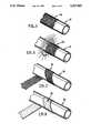
- FIGS. 4 to 8are partial perspective views illustrating modifications that may be incorporated in the module for assuring permeate flow to the permeate outlet of the module.
- FIG. 1shows a tubular membrane module that was developed primarily for use in an ultrafiltration apparatus, for example for separating oil from water.
- the apparatusitself has not been shown since it is not part of the present invention, and may be conventional.
- the moduleis denoted generally by reference numeral 20.
- the modulemay have an overall length of approximately 10 feet and a nominal external diameter corresponding to the diameter of standard PVC pipe of 1 inch internal diameter.
- An ultrafiltration unitwill normally include at least one array or bank of similar modules coupled together for series flow of fluid through at least several of the modules.
- Module 20includes a tubular shell 22 which has first and second end portions 22a and 22b respectively and a permeate outlet 24 adjacent end 22b.
- the shellis made of a standard length of 1 inch ID PVC pipe as indicated previously.
- Respective end fittings 26 and 28are provided at opposite ends of the shell and are designed to permit the module to be coupled to external components for permitting fluid flow through the module.
- fitting 26is at the inlet end of the module and fitting 28 at the outlet end. Fluid to be filtered will enter the module under pressure through fitting 26 and the filtered fluid will leave through fitting 28 while permeate will leave through outlet 24.
- outlet 24is a threaded hole in the wall of shell 22 into which a suitable outlet fitting (not shown) can be secured by adhesive.
- FIGS. 2 and 3show end fitting 28 only but may be taken as representative of both ends of the module because the two end fittings are identical.
- Membrane tube 30comprises a porous pipe 30a having a permeable membrane 30b on its inner surface (see FIG. 3a).
- the pipeis a polyester straw made from spirally wound polyester tape impregnated with "dots" of polyethylene or polypropylene, or other plastic material which are thermally activated to bond together the wound tape and form a rigid pipe.
- a polypropylene strawmay be used as an alternative.
- the semi-permeable membraneis cast onto the inside surface of the pipe as it is made.
- the structure of the membrane tube and its method of manufacturehave not been specifically illustrated in the drawings since they will be familiar to a person skilled in the art.
- other types of pipemay be used within the broad scope of the invention, for example a porous FRP (fibre-reinforced plastic) pipe with a suitable liner at the inner surface.
- the two end fittings 26 and 28 of the moduleare injection moulded in PVC. Fitting 28 will now be described as representative of both fittings.
- the fittinghas inner and outer end portions denoted respectively 32 and 34 separated by a collar 35 that provides a flange for mounting the module in the ultrafiltration unit.
- the inner end portion 32 of the fittinghas a tubular internal surface 36 that is dimensioned to make surface-to-surface contact with a corresponding tubular surface portion 38 at the relevant end of shell 22.
- the fitting end portion 32is essentially a cylindrical sleeve dimensioned to closely receive the end portion 38 of end portion 22b.
- a shoulder 40 within the fittingdefines the fully inserted position of the shell.
- the mating surfaces 36 and 38are secured together by an epoxy resin adhesive so that each end fitting 26 and 28 is sealed to each end of the shell.
- the shellcould be designed to fit over and be secured to the external surface of fitting end portion 32.
- the outer end portion 34 of the fittingalso has the form of a cylindrical sleeve; in this case, the sleeve is provided with an external screw thread 42 by which the fitting (and hence the module) can be coupled to appropriate components of the filtration unit itself.
- the fittingInwardly of tubular surface 36, the fitting is provided with a socket 44 having a blind end 46 dimensioned to closely receive the relevant end portion of the membrane tube 30.
- the tube end portionis secured by epoxy resin adhesive within socket 44 with its end face fully seated against the blind end 46.
- a port 48 of smaller diameter than and within the blind end 46provides communication between the interior of the membrane tube 30 and the exterior of the fitting, through the outer end portion 34 thereof. It will be seen that the blind end 46 of socket 44 in effect forms an undercut with respect to port 48 leaving a shoulder 50 between the port and tube 30. Shoulder 50 protects the tube from the effects of fluid shear caused by fluid entering tube 30 from port 48 under pressure. The fluid shear effect could otherwise cause the membrane to be stripped from the inner surface of the membrane tube.
- Assembly of the modulewill be effected by first cutting shell 22 and membrane tube 30 to length (if necessary) and then assembling one end of the module. This will be done by simply coating corresponding end portions of the shell and tube with adhesive and assembling them to the relevant end fitting 26 or 28. The opposite ends of the tube and shell will then be coated with adhesive and the other end fitting secured in place. There will be no need to take special precautions to support the components during curing or to allow lengthy curing periods as is necessary with the prior art designs.
- the resulting structurewill be monolithic in nature with a high resistance to fluid leakage either around the membrane tube and into the space between the tube and shell or from the shell itself.
- the moduleis provided with means to define at least one permeate channel between the membrane tube and the shell, for assuring permeate flow to the permeate outlet when the module is in use. Preferably, this is accomplished by providing relatively incompressible spacer means on the interior of the shell or the exterior of the membrane tube. The spacer means should preferably not significantly inhibit uniform flow of permeate through the tube wall, circumferentially or longitudinally.
- FIGS. 4 to 8Examples of possible spacer means as shown in FIGS. 4 to 8 will now be described. Generally, the examples are alternatives although two or more could conceivably be used together if necessary.
- FIG. 4shows an embodiment in which the internal surface of the shell of the module is grooved to provide channels to the permeate outlet.
- the shellis denoted by reference numeral 22' and the permeate outlet of the shell is denoted 24'.
- the outletis defined by an integrally moulded, internally screw-threaded collar 52.
- the internal surface of shell 22'is formed with a series of angularly spaced, longitudinally extending grooves 54, defining intervening lands 56.
- the lands 56mechanically space the exterior of the membrane tube from the interior of the shell so that permeate flowing through the shell can travel along the grooves towards the permeate outlet.
- a circumferential groove 58intersects the longitudinal grooves 54 at the position of the permeate outlet to convey permeate from those grooves to the outlet.
- FIGS. 5 to 8illustrate modifications of the membrane tube to provide mechanical spacer means.
- the tube itselfis the same as the tube shown in the previous views and is denoted by reference numeral 30.
- the other components of the modulehave not been shown and may be as described previously; the shell of the module could be modified as shown in FIG. 4 but normally it will not be necessary to use an internally grooved shell.
- the membrane tubeis provided with an external sock or sleeve 60 made of an appropriate woven material which provides the required mechanical spacing coupled with permeate flow channels through the material.
- a suitable materialis available under the trade mark VEXAR from Nalle Plastics of Texas. This type of material is characterized as woven packing material and comprises woven filaments formed with external projections or "bumps" to provide mechanical spacing.
- Sock 60is a relatively close fit around the membrane tube and, in the assembled module, is held in place as a result of being trapped between the tube and the shell when the tube is under pressure in use.
- An adhesivemay also be used to hold the sock in place.
- the sockterminates short of the end portions of the tube that are sealed to the end fittings of the module.
- FIG. 6illustrates a sock 62 that is braided in place on the tube during its manufacture. Braiding may be effected using a conventional braiding machine (not shown) and the braided sock may be formed from filaments of any appropriate type, for example VEXAR filaments. Again, the sock may be trapped and/or secured in place by adhesive.
- FIGS. 7 and 8illustrate methods of providing a mechanical spacer by spirally winding a tape of material around a tube.
- the tapeis denoted by reference numeral 64 and is a woven material, again possibly made of VEXAR.
- the tapeis denoted 66 and is formed of a porous material which is relatively incompressible while at the same time providing permeate flow channels through the material.
- suitable materialare porous plastic material such as polyethylene, polypropylene and polyester and porous stainless steel, for example in the form of a screen-like mesh.
- the tapesmay be wound spirally around the membrane tube with the turns of the spiral abutting one another, or the turns may be spaced; overlapping would be generally undesirable.
- the tapewill be secured to the membrane tube, at least at its ends, for example by means of a suitable adhesive.
- adhesive sealing of the outer shell 22 to the tubular surface of the end fitting at one end of the modulecould be replaced by an 0-ring seal that would allow for relative axial movement between the shell and end fitting to accommodate axial expansion and contraction of the shell with respect to membrane tube 30 due to thermal effects.
- the shellwill normally be of cylindrical shape and the end fittings will be correspondingly shaped and have cylindrical outer end portions.
- the end fittingswill be correspondingly shaped and have cylindrical outer end portions.
- other tubular shapescould be used.
- module shellmay be made of plastic materials other than PVC (e.g. CPVC, polyurethane or PVDF) or stainless steel.
Landscapes
- Chemical & Material Sciences (AREA)
- Chemical Kinetics & Catalysis (AREA)
- Separation Using Semi-Permeable Membranes (AREA)
Abstract
Description
Claims (16)
Priority Applications (3)
| Application Number | Priority Date | Filing Date | Title |
|---|---|---|---|
| US07/501,997US5227063A (en) | 1989-10-03 | 1990-03-30 | Tubular membrane module |
| AU64468/90AAU6446890A (en) | 1989-10-03 | 1990-09-28 | Tubular membrane module |
| PCT/CA1990/000331WO1991004784A1 (en) | 1989-10-03 | 1990-09-28 | Tubular membrane module |
Applications Claiming Priority (2)
| Application Number | Priority Date | Filing Date | Title |
|---|---|---|---|
| US41657489A | 1989-10-03 | 1989-10-03 | |
| US07/501,997US5227063A (en) | 1989-10-03 | 1990-03-30 | Tubular membrane module |
Related Parent Applications (1)
| Application Number | Title | Priority Date | Filing Date |
|---|---|---|---|
| US41657489AContinuation-In-Part | 1989-10-03 | 1989-10-03 |
Publications (1)
| Publication Number | Publication Date |
|---|---|
| US5227063Atrue US5227063A (en) | 1993-07-13 |
Family
ID=27023406
Family Applications (1)
| Application Number | Title | Priority Date | Filing Date |
|---|---|---|---|
| US07/501,997Expired - LifetimeUS5227063A (en) | 1989-10-03 | 1990-03-30 | Tubular membrane module |
Country Status (3)
| Country | Link |
|---|---|
| US (1) | US5227063A (en) |
| AU (1) | AU6446890A (en) |
| WO (1) | WO1991004784A1 (en) |
Cited By (68)
| Publication number | Priority date | Publication date | Assignee | Title |
|---|---|---|---|---|
| US5373456A (en)* | 1992-11-02 | 1994-12-13 | The United States Of America As Represented By The Secretary Of The Navy | Expert system for assessing accuracy of models of physical phenomena and for selecting alternate models in the presence of noise |
| US6030436A (en)* | 1998-09-14 | 2000-02-29 | Valco Instruments Company, Inc. | Permeation tube for delivering fluid at a constant flow rate independent of ambient temperature variations |
| US6063277A (en)* | 1998-03-13 | 2000-05-16 | Celgard Inc. | Fiber-reinforced, composite body contactors |
| US6228146B1 (en) | 2000-03-03 | 2001-05-08 | Don R. Kuespert | Gas recovery device |
| US20030089659A1 (en)* | 2000-04-10 | 2003-05-15 | Fufang Zha | Hollow fibre restraining system |
| US20030178365A1 (en)* | 1996-12-20 | 2003-09-25 | Fufang Zha | Scouring method |
| US20030205519A1 (en)* | 1998-09-25 | 2003-11-06 | Fufang Zha | Apparatus and method for cleaning membrane filtration modules |
| US20030226797A1 (en)* | 2000-10-23 | 2003-12-11 | Roger Phelps | Fibre membrane arrangement |
| US20030234221A1 (en)* | 2000-10-09 | 2003-12-25 | U.S. Filter Wastewater Group, Inc. | Membrane filtration system |
| US20040000520A1 (en)* | 2001-11-16 | 2004-01-01 | Gallagher Paul Martin | Method of cleaning membranes |
| US20040035782A1 (en)* | 2000-11-13 | 2004-02-26 | Heinz-Joachim Muller | Modified membranes |
| US20040232076A1 (en)* | 1996-12-20 | 2004-11-25 | Fufang Zha | Scouring method |
| US20040238442A1 (en)* | 2001-09-18 | 2004-12-02 | Johnson Warren Thomas | High solids module |
| US20040238431A1 (en)* | 1999-04-20 | 2004-12-02 | Johnson Warren Thomas | Membrane filtration manifold system |
| US20050087898A1 (en)* | 2001-04-04 | 2005-04-28 | U. S. Filter Wastewater Group, Inc. | Potting method |
| US20070084795A1 (en)* | 2005-10-05 | 2007-04-19 | Jordan Edward J | Method and system for treating wastewater |
| US7226541B2 (en) | 2001-06-20 | 2007-06-05 | Siemens Water Technology Corp. | Membrane polymer compositions |
| US7247238B2 (en) | 2002-02-12 | 2007-07-24 | Siemens Water Technologies Corp. | Poly(ethylene chlorotrifluoroethylene) membranes |
| US20070256561A1 (en)* | 2006-05-01 | 2007-11-08 | Nitto Denko Corporation | Degassing apparatus |
| US7387723B2 (en) | 2004-04-22 | 2008-06-17 | Siemens Water Technologies Corp. | Filtration apparatus comprising a membrane bioreactor and a treatment vessel for digesting organic materials |
| US7455765B2 (en) | 2006-01-25 | 2008-11-25 | Siemens Water Technologies Corp. | Wastewater treatment system and method |
| US7563363B2 (en) | 2005-10-05 | 2009-07-21 | Siemens Water Technologies Corp. | System for treating wastewater |
| US7591950B2 (en) | 2004-11-02 | 2009-09-22 | Siemens Water Technologies Corp. | Submerged cross-flow filtration |
| US20090314708A1 (en)* | 2008-06-18 | 2009-12-24 | Sepratek Inc. | Hollow fiber membrane for feeding mixture into hollow space thereof |
| US20100072124A1 (en)* | 2006-09-19 | 2010-03-25 | Hirofumi Morikawa | Hollow fiber membrane module |
| US7718057B2 (en) | 2005-10-05 | 2010-05-18 | Siemens Water Technologies Corp. | Wastewater treatment system |
| US20100218912A1 (en)* | 2008-04-07 | 2010-09-02 | Lane Lawless | Method, apparatus, header, and composition for ground heat exchange |
| US7819956B2 (en) | 2004-07-02 | 2010-10-26 | Siemens Water Technologies Corp. | Gas transfer membrane |
| US7862719B2 (en) | 2004-08-20 | 2011-01-04 | Siemens Water Technologies Corp. | Square membrane manifold system |
| US7867417B2 (en) | 2004-12-03 | 2011-01-11 | Siemens Water Technologies Corp. | Membrane post treatment |
| US7938966B2 (en) | 2002-10-10 | 2011-05-10 | Siemens Water Technologies Corp. | Backwash method |
| US7988891B2 (en) | 2005-07-14 | 2011-08-02 | Siemens Industry, Inc. | Monopersulfate treatment of membranes |
| US8057574B2 (en) | 2003-07-08 | 2011-11-15 | Siemens Industry, Inc. | Membrane post treatment |
| US20120111783A1 (en)* | 2007-11-16 | 2012-05-10 | Cott Technologies, Inc. | Permeate tube and related methods |
| US8182687B2 (en) | 2002-06-18 | 2012-05-22 | Siemens Industry, Inc. | Methods of minimising the effect of integrity loss in hollow fibre membrane modules |
| US8268176B2 (en) | 2003-08-29 | 2012-09-18 | Siemens Industry, Inc. | Backwash |
| US8287743B2 (en) | 2007-05-29 | 2012-10-16 | Siemens Industry, Inc. | Membrane cleaning with pulsed airlift pump |
| US8293098B2 (en) | 2006-10-24 | 2012-10-23 | Siemens Industry, Inc. | Infiltration/inflow control for membrane bioreactor |
| US8318028B2 (en) | 2007-04-02 | 2012-11-27 | Siemens Industry, Inc. | Infiltration/inflow control for membrane bioreactor |
| US8372282B2 (en) | 2002-12-05 | 2013-02-12 | Siemens Industry, Inc. | Mixing chamber |
| US8377305B2 (en) | 2004-09-15 | 2013-02-19 | Siemens Industry, Inc. | Continuously variable aeration |
| US8382981B2 (en) | 2008-07-24 | 2013-02-26 | Siemens Industry, Inc. | Frame system for membrane filtration modules |
| US8496828B2 (en) | 2004-12-24 | 2013-07-30 | Siemens Industry, Inc. | Cleaning in membrane filtration systems |
| US8506806B2 (en) | 2004-09-14 | 2013-08-13 | Siemens Industry, Inc. | Methods and apparatus for removing solids from a membrane module |
| US8512568B2 (en) | 2001-08-09 | 2013-08-20 | Siemens Industry, Inc. | Method of cleaning membrane modules |
| US8524794B2 (en) | 2004-07-05 | 2013-09-03 | Siemens Industry, Inc. | Hydrophilic membranes |
| US8652331B2 (en) | 2008-08-20 | 2014-02-18 | Siemens Water Technologies Llc | Membrane system backwash energy efficiency |
| US8758622B2 (en) | 2004-12-24 | 2014-06-24 | Evoqua Water Technologies Llc | Simple gas scouring method and apparatus |
| US8758621B2 (en) | 2004-03-26 | 2014-06-24 | Evoqua Water Technologies Llc | Process and apparatus for purifying impure water using microfiltration or ultrafiltration in combination with reverse osmosis |
| US8790515B2 (en) | 2004-09-07 | 2014-07-29 | Evoqua Water Technologies Llc | Reduction of backwash liquid waste |
| US8808540B2 (en) | 2003-11-14 | 2014-08-19 | Evoqua Water Technologies Llc | Module cleaning method |
| US8858796B2 (en) | 2005-08-22 | 2014-10-14 | Evoqua Water Technologies Llc | Assembly for water filtration using a tube manifold to minimise backwash |
| US8956464B2 (en) | 2009-06-11 | 2015-02-17 | Evoqua Water Technologies Llc | Method of cleaning membranes |
| US9022224B2 (en) | 2010-09-24 | 2015-05-05 | Evoqua Water Technologies Llc | Fluid control manifold for membrane filtration system |
| US9533261B2 (en) | 2012-06-28 | 2017-01-03 | Evoqua Water Technologies Llc | Potting method |
| US9604166B2 (en) | 2011-09-30 | 2017-03-28 | Evoqua Water Technologies Llc | Manifold arrangement |
| US9675938B2 (en) | 2005-04-29 | 2017-06-13 | Evoqua Water Technologies Llc | Chemical clean for membrane filter |
| US9764289B2 (en) | 2012-09-26 | 2017-09-19 | Evoqua Water Technologies Llc | Membrane securement device |
| US9764288B2 (en) | 2007-04-04 | 2017-09-19 | Evoqua Water Technologies Llc | Membrane module protection |
| US9815027B2 (en) | 2012-09-27 | 2017-11-14 | Evoqua Water Technologies Llc | Gas scouring apparatus for immersed membranes |
| US9868834B2 (en) | 2012-09-14 | 2018-01-16 | Evoqua Water Technologies Llc | Polymer blend for membranes |
| US9873088B2 (en) | 2011-05-17 | 2018-01-23 | Natrix Separations Inc. | Layered tubular membranes for chromatography, and methods of use thereof |
| US9914097B2 (en) | 2010-04-30 | 2018-03-13 | Evoqua Water Technologies Llc | Fluid flow distribution device |
| US9925499B2 (en) | 2011-09-30 | 2018-03-27 | Evoqua Water Technologies Llc | Isolation valve with seal for end cap of a filtration system |
| US9962865B2 (en) | 2012-09-26 | 2018-05-08 | Evoqua Water Technologies Llc | Membrane potting methods |
| US10322375B2 (en) | 2015-07-14 | 2019-06-18 | Evoqua Water Technologies Llc | Aeration device for filtration system |
| US10427102B2 (en) | 2013-10-02 | 2019-10-01 | Evoqua Water Technologies Llc | Method and device for repairing a membrane filtration module |
| US10800808B2 (en) | 2008-09-02 | 2020-10-13 | Merck Millipore Ltd. | Chromatography membranes, devices containing them, and methods of use thereof |
Families Citing this family (9)
| Publication number | Priority date | Publication date | Assignee | Title |
|---|---|---|---|---|
| WO1993017780A1 (en)* | 1992-03-13 | 1993-09-16 | Nauchno-Proizvodstvennoe Obiedinenie 'polimersintez' | Tubular module for filtration at tangential passage of mixture to be separated |
| DE9206870U1 (en)* | 1992-05-21 | 1993-06-17 | WAP Reinigungssysteme GmbH & Co, 7919 Bellenberg | Tube module for ultrafiltration |
| RU2139130C1 (en)* | 1998-03-12 | 1999-10-10 | Кемеровский технологический институт пищевой промышленности | Diaphragm concentration apparatus |
| RU2181619C1 (en)* | 2000-10-27 | 2002-04-27 | Кемеровский технологический институт пищевой промышленности | Gear for membrane concentration |
| RU2217224C1 (en)* | 2002-05-27 | 2003-11-27 | Кемеровский технологический институт пищевой промышленности | Membrane-type concentration apparatus |
| RU2234360C2 (en)* | 2002-05-27 | 2004-08-20 | Кемеровский технологический институт пищевой промышленности | Apparatus for membranous concentrating |
| RU2251446C1 (en)* | 2004-03-01 | 2005-05-10 | Государственное образовательное учреждение высшего профессионального образования Воронежская государственная технологическая академия | Membrane device for viscous liquid filtration |
| RU2429053C2 (en)* | 2009-11-24 | 2011-09-20 | Борис Анатольевич Лобасенко | Membrane concentration apparatus |
| RU2607664C1 (en)* | 2015-09-09 | 2017-01-10 | Федеральное государственное бюджетное образовательное учреждение высшего образования "Кемеровский технологический институт пищевой промышленности (университет)" | Membrane concentration device |
Citations (5)
| Publication number | Priority date | Publication date | Assignee | Title |
|---|---|---|---|---|
| US3965012A (en)* | 1973-12-11 | 1976-06-22 | Kanegafuchi Kagaku Kogyo Kabushiki Kaisha | Membrane separation apparatus |
| US4309287A (en)* | 1980-05-01 | 1982-01-05 | Abcor, Inc. | Reverse-osmosis tubular membrane |
| US4339334A (en)* | 1978-07-28 | 1982-07-13 | Kanegafuchi Kagaku Kogyo Kabushiki Kaisha | Tubular membrane separation apparatus end joint seal |
| US4517720A (en)* | 1981-12-21 | 1985-05-21 | Monsanto Company | Method of mounting a fluid separation module in a tubular shell |
| US4612119A (en)* | 1983-04-09 | 1986-09-16 | Kanegafuchi Kagaku Kogyo Kabushiki Kaisha | Hollow fiber filter medium and process for preparing the same |
Family Cites Families (8)
| Publication number | Priority date | Publication date | Assignee | Title |
|---|---|---|---|---|
| FR1503839A (en)* | 1966-10-14 | 1967-12-01 | Sfec | Assembly of tubular semi-permeable membranes using non-porous and non-perforated sheaths |
| US3795317A (en)* | 1972-01-17 | 1974-03-05 | Wavin Bv | System for reversed osmosis |
| JPS5464085A (en)* | 1977-11-01 | 1979-05-23 | Mitsubishi Rayon Co Ltd | Separator for fluids |
| JPS5495983A (en)* | 1978-01-12 | 1979-07-28 | Sumitomo Electric Ind Ltd | End structure of tubular module |
| JPS551893A (en)* | 1979-05-18 | 1980-01-09 | Agency Of Ind Science & Technol | Pipe type membrane separator using pipe type membrane structure |
| DE3024504A1 (en)* | 1979-07-09 | 1982-01-28 | Liviu Dipl.-Ing. 6509 Framersheim Enea | Ultrafiltration tube joint - with thickened end piece on outer tube engaging union nut on other tube |
| US4400019A (en)* | 1981-04-22 | 1983-08-23 | Unisert Systems, Inc. | Multilayer pipe joint |
| US4897191A (en)* | 1988-05-27 | 1990-01-30 | Zenon Environmental Inc. | Tubular membrane module with fluid shear protection |
- 1990
- 1990-03-30USUS07/501,997patent/US5227063A/ennot_activeExpired - Lifetime
- 1990-09-28WOPCT/CA1990/000331patent/WO1991004784A1/enunknown
- 1990-09-28AUAU64468/90Apatent/AU6446890A/ennot_activeAbandoned
Patent Citations (5)
| Publication number | Priority date | Publication date | Assignee | Title |
|---|---|---|---|---|
| US3965012A (en)* | 1973-12-11 | 1976-06-22 | Kanegafuchi Kagaku Kogyo Kabushiki Kaisha | Membrane separation apparatus |
| US4339334A (en)* | 1978-07-28 | 1982-07-13 | Kanegafuchi Kagaku Kogyo Kabushiki Kaisha | Tubular membrane separation apparatus end joint seal |
| US4309287A (en)* | 1980-05-01 | 1982-01-05 | Abcor, Inc. | Reverse-osmosis tubular membrane |
| US4517720A (en)* | 1981-12-21 | 1985-05-21 | Monsanto Company | Method of mounting a fluid separation module in a tubular shell |
| US4612119A (en)* | 1983-04-09 | 1986-09-16 | Kanegafuchi Kagaku Kogyo Kabushiki Kaisha | Hollow fiber filter medium and process for preparing the same |
Cited By (115)
| Publication number | Priority date | Publication date | Assignee | Title |
|---|---|---|---|---|
| US5373456A (en)* | 1992-11-02 | 1994-12-13 | The United States Of America As Represented By The Secretary Of The Navy | Expert system for assessing accuracy of models of physical phenomena and for selecting alternate models in the presence of noise |
| US20040168979A1 (en)* | 1996-12-20 | 2004-09-02 | Fufang Zha | Scouring method |
| US8048306B2 (en) | 1996-12-20 | 2011-11-01 | Siemens Industry, Inc. | Scouring method |
| US20030178365A1 (en)* | 1996-12-20 | 2003-09-25 | Fufang Zha | Scouring method |
| US20040084369A1 (en)* | 1996-12-20 | 2004-05-06 | U.S. Filter Wastewater Group, Inc. | Scouring method |
| US20040232076A1 (en)* | 1996-12-20 | 2004-11-25 | Fufang Zha | Scouring method |
| US20040178154A1 (en)* | 1996-12-20 | 2004-09-16 | Pall Filtration And Separations Group Inc. | Scouring method |
| US6063277A (en)* | 1998-03-13 | 2000-05-16 | Celgard Inc. | Fiber-reinforced, composite body contactors |
| US6030436A (en)* | 1998-09-14 | 2000-02-29 | Valco Instruments Company, Inc. | Permeation tube for delivering fluid at a constant flow rate independent of ambient temperature variations |
| US6821420B2 (en) | 1998-09-25 | 2004-11-23 | U. S. Filter Wastewater Group, Inc. | Apparatus and method for cleaning membrane filtration modules |
| US20030205519A1 (en)* | 1998-09-25 | 2003-11-06 | Fufang Zha | Apparatus and method for cleaning membrane filtration modules |
| US20040238431A1 (en)* | 1999-04-20 | 2004-12-02 | Johnson Warren Thomas | Membrane filtration manifold system |
| US7264716B2 (en) | 1999-04-20 | 2007-09-04 | Siemens Water Technologies Corp. | Membrane filtration manifold system |
| US6228146B1 (en) | 2000-03-03 | 2001-05-08 | Don R. Kuespert | Gas recovery device |
| US20030089659A1 (en)* | 2000-04-10 | 2003-05-15 | Fufang Zha | Hollow fibre restraining system |
| US6962258B2 (en) | 2000-04-10 | 2005-11-08 | U.S. Filter Wastewater Group, Inc. | Hollow fiber restraining system |
| US6783008B2 (en) | 2000-04-10 | 2004-08-31 | U.S. Filter Wastewater Group, Inc. | Hollow fibre restraining system |
| US20070209993A1 (en)* | 2000-04-10 | 2007-09-13 | Fufang Zha | Hollow fibre restraining system |
| US20040262215A1 (en)* | 2000-04-10 | 2004-12-30 | Fufang Zha | Hollow fibre restraining system |
| US6872305B2 (en) | 2000-10-09 | 2005-03-29 | U.S. Filter Wastewater Group, Inc. | Membrane filtration system |
| US20030234221A1 (en)* | 2000-10-09 | 2003-12-25 | U.S. Filter Wastewater Group, Inc. | Membrane filtration system |
| US20030226797A1 (en)* | 2000-10-23 | 2003-12-11 | Roger Phelps | Fibre membrane arrangement |
| US20040035782A1 (en)* | 2000-11-13 | 2004-02-26 | Heinz-Joachim Muller | Modified membranes |
| US6884350B2 (en) | 2000-11-13 | 2005-04-26 | U.S. Filter Wastewater Group, Inc. | Modified membranes |
| US7404896B2 (en) | 2000-11-13 | 2008-07-29 | Siemens Water Technologies Corp. | Modified membranes |
| US20050029185A1 (en)* | 2000-11-13 | 2005-02-10 | Heinz-Joachim Muller | Modified membranes |
| US7300022B2 (en) | 2000-11-13 | 2007-11-27 | Siemens Water Technologies Corp. | Modified membranes |
| US20050087898A1 (en)* | 2001-04-04 | 2005-04-28 | U. S. Filter Wastewater Group, Inc. | Potting method |
| US6974554B2 (en) | 2001-04-04 | 2005-12-13 | U.S. Filter Wastewater Group, Inc. | Potting method |
| US8518256B2 (en) | 2001-04-04 | 2013-08-27 | Siemens Industry, Inc. | Membrane module |
| US7931463B2 (en) | 2001-04-04 | 2011-04-26 | Siemens Water Technologies Corp. | Apparatus for potting membranes |
| US7226541B2 (en) | 2001-06-20 | 2007-06-05 | Siemens Water Technology Corp. | Membrane polymer compositions |
| US8512568B2 (en) | 2001-08-09 | 2013-08-20 | Siemens Industry, Inc. | Method of cleaning membrane modules |
| US20040238442A1 (en)* | 2001-09-18 | 2004-12-02 | Johnson Warren Thomas | High solids module |
| US7018533B2 (en) | 2001-09-18 | 2006-03-28 | U.S. Filter Wastewater Group, Inc. | High solids module |
| US6955762B2 (en) | 2001-11-16 | 2005-10-18 | U. S. Filter Wastewater Group, Inc. | Method of cleaning membranes |
| US20050218073A1 (en)* | 2001-11-16 | 2005-10-06 | Gallagher Paul M | Method of cleaning membranes |
| US20040000520A1 (en)* | 2001-11-16 | 2004-01-01 | Gallagher Paul Martin | Method of cleaning membranes |
| US7247238B2 (en) | 2002-02-12 | 2007-07-24 | Siemens Water Technologies Corp. | Poly(ethylene chlorotrifluoroethylene) membranes |
| US7632439B2 (en) | 2002-02-12 | 2009-12-15 | Siemens Water Technologies Corp. | Poly(ethylene chlorotrifluoroethylene) membranes |
| US8182687B2 (en) | 2002-06-18 | 2012-05-22 | Siemens Industry, Inc. | Methods of minimising the effect of integrity loss in hollow fibre membrane modules |
| US7938966B2 (en) | 2002-10-10 | 2011-05-10 | Siemens Water Technologies Corp. | Backwash method |
| US8372282B2 (en) | 2002-12-05 | 2013-02-12 | Siemens Industry, Inc. | Mixing chamber |
| US8057574B2 (en) | 2003-07-08 | 2011-11-15 | Siemens Industry, Inc. | Membrane post treatment |
| US8262778B2 (en) | 2003-07-08 | 2012-09-11 | Siemens Industry, Inc. | Membrane post treatment |
| US8268176B2 (en) | 2003-08-29 | 2012-09-18 | Siemens Industry, Inc. | Backwash |
| US8808540B2 (en) | 2003-11-14 | 2014-08-19 | Evoqua Water Technologies Llc | Module cleaning method |
| US8758621B2 (en) | 2004-03-26 | 2014-06-24 | Evoqua Water Technologies Llc | Process and apparatus for purifying impure water using microfiltration or ultrafiltration in combination with reverse osmosis |
| US7718065B2 (en) | 2004-04-22 | 2010-05-18 | Siemens Water Technologies Corp. | Filtration method and apparatus |
| US7387723B2 (en) | 2004-04-22 | 2008-06-17 | Siemens Water Technologies Corp. | Filtration apparatus comprising a membrane bioreactor and a treatment vessel for digesting organic materials |
| US7819956B2 (en) | 2004-07-02 | 2010-10-26 | Siemens Water Technologies Corp. | Gas transfer membrane |
| US8524794B2 (en) | 2004-07-05 | 2013-09-03 | Siemens Industry, Inc. | Hydrophilic membranes |
| US7862719B2 (en) | 2004-08-20 | 2011-01-04 | Siemens Water Technologies Corp. | Square membrane manifold system |
| US8790515B2 (en) | 2004-09-07 | 2014-07-29 | Evoqua Water Technologies Llc | Reduction of backwash liquid waste |
| US8506806B2 (en) | 2004-09-14 | 2013-08-13 | Siemens Industry, Inc. | Methods and apparatus for removing solids from a membrane module |
| US8377305B2 (en) | 2004-09-15 | 2013-02-19 | Siemens Industry, Inc. | Continuously variable aeration |
| US7591950B2 (en) | 2004-11-02 | 2009-09-22 | Siemens Water Technologies Corp. | Submerged cross-flow filtration |
| US7867417B2 (en) | 2004-12-03 | 2011-01-11 | Siemens Water Technologies Corp. | Membrane post treatment |
| US8496828B2 (en) | 2004-12-24 | 2013-07-30 | Siemens Industry, Inc. | Cleaning in membrane filtration systems |
| US8758622B2 (en) | 2004-12-24 | 2014-06-24 | Evoqua Water Technologies Llc | Simple gas scouring method and apparatus |
| US9675938B2 (en) | 2005-04-29 | 2017-06-13 | Evoqua Water Technologies Llc | Chemical clean for membrane filter |
| US7988891B2 (en) | 2005-07-14 | 2011-08-02 | Siemens Industry, Inc. | Monopersulfate treatment of membranes |
| US8894858B1 (en) | 2005-08-22 | 2014-11-25 | Evoqua Water Technologies Llc | Method and assembly for water filtration using a tube manifold to minimize backwash |
| US8858796B2 (en) | 2005-08-22 | 2014-10-14 | Evoqua Water Technologies Llc | Assembly for water filtration using a tube manifold to minimise backwash |
| US7722769B2 (en) | 2005-10-05 | 2010-05-25 | Siemens Water Technologies Corp. | Method for treating wastewater |
| US7563363B2 (en) | 2005-10-05 | 2009-07-21 | Siemens Water Technologies Corp. | System for treating wastewater |
| US7718057B2 (en) | 2005-10-05 | 2010-05-18 | Siemens Water Technologies Corp. | Wastewater treatment system |
| US20070084795A1 (en)* | 2005-10-05 | 2007-04-19 | Jordan Edward J | Method and system for treating wastewater |
| US7455765B2 (en) | 2006-01-25 | 2008-11-25 | Siemens Water Technologies Corp. | Wastewater treatment system and method |
| US7708811B2 (en)* | 2006-05-01 | 2010-05-04 | Nitto Denko Corporation | Degassing apparatus |
| US20070256561A1 (en)* | 2006-05-01 | 2007-11-08 | Nitto Denko Corporation | Degassing apparatus |
| US8307991B2 (en)* | 2006-09-19 | 2012-11-13 | Toray Industries Inc. | Hollow fiber membrane module |
| US20100072124A1 (en)* | 2006-09-19 | 2010-03-25 | Hirofumi Morikawa | Hollow fiber membrane module |
| US8293098B2 (en) | 2006-10-24 | 2012-10-23 | Siemens Industry, Inc. | Infiltration/inflow control for membrane bioreactor |
| US8318028B2 (en) | 2007-04-02 | 2012-11-27 | Siemens Industry, Inc. | Infiltration/inflow control for membrane bioreactor |
| US8623202B2 (en) | 2007-04-02 | 2014-01-07 | Siemens Water Technologies Llc | Infiltration/inflow control for membrane bioreactor |
| US9764288B2 (en) | 2007-04-04 | 2017-09-19 | Evoqua Water Technologies Llc | Membrane module protection |
| US8622222B2 (en) | 2007-05-29 | 2014-01-07 | Siemens Water Technologies Llc | Membrane cleaning with pulsed airlift pump |
| US9573824B2 (en) | 2007-05-29 | 2017-02-21 | Evoqua Water Technologies Llc | Membrane cleaning with pulsed airlift pump |
| US8287743B2 (en) | 2007-05-29 | 2012-10-16 | Siemens Industry, Inc. | Membrane cleaning with pulsed airlift pump |
| US8840783B2 (en) | 2007-05-29 | 2014-09-23 | Evoqua Water Technologies Llc | Water treatment membrane cleaning with pulsed airlift pump |
| US8372276B2 (en) | 2007-05-29 | 2013-02-12 | Siemens Industry, Inc. | Membrane cleaning with pulsed airlift pump |
| US9206057B2 (en) | 2007-05-29 | 2015-12-08 | Evoqua Water Technologies Llc | Membrane cleaning with pulsed airlift pump |
| US10507431B2 (en) | 2007-05-29 | 2019-12-17 | Evoqua Water Technologies Llc | Membrane cleaning with pulsed airlift pump |
| US10232317B2 (en)* | 2007-11-16 | 2019-03-19 | Cott Technologies, Inc. | Permeate tube and related methods |
| US20120111783A1 (en)* | 2007-11-16 | 2012-05-10 | Cott Technologies, Inc. | Permeate tube and related methods |
| US9816023B2 (en)* | 2008-04-07 | 2017-11-14 | Rygan Corp | Method, apparatus, header, and composition for ground heat exchange |
| US20100218912A1 (en)* | 2008-04-07 | 2010-09-02 | Lane Lawless | Method, apparatus, header, and composition for ground heat exchange |
| US20090314708A1 (en)* | 2008-06-18 | 2009-12-24 | Sepratek Inc. | Hollow fiber membrane for feeding mixture into hollow space thereof |
| US9023206B2 (en) | 2008-07-24 | 2015-05-05 | Evoqua Water Technologies Llc | Frame system for membrane filtration modules |
| US8382981B2 (en) | 2008-07-24 | 2013-02-26 | Siemens Industry, Inc. | Frame system for membrane filtration modules |
| US8652331B2 (en) | 2008-08-20 | 2014-02-18 | Siemens Water Technologies Llc | Membrane system backwash energy efficiency |
| US10800808B2 (en) | 2008-09-02 | 2020-10-13 | Merck Millipore Ltd. | Chromatography membranes, devices containing them, and methods of use thereof |
| US10981949B2 (en) | 2008-09-02 | 2021-04-20 | Merck Millipore Ltd. | Chromatography membranes, devices containing them, and methods of use thereof |
| US11884701B2 (en) | 2008-09-02 | 2024-01-30 | Merck Millipore Ltd. | Chromatography membranes, devices containing them, and methods of use thereof |
| US8956464B2 (en) | 2009-06-11 | 2015-02-17 | Evoqua Water Technologies Llc | Method of cleaning membranes |
| US10441920B2 (en) | 2010-04-30 | 2019-10-15 | Evoqua Water Technologies Llc | Fluid flow distribution device |
| US9914097B2 (en) | 2010-04-30 | 2018-03-13 | Evoqua Water Technologies Llc | Fluid flow distribution device |
| US9022224B2 (en) | 2010-09-24 | 2015-05-05 | Evoqua Water Technologies Llc | Fluid control manifold for membrane filtration system |
| US9630147B2 (en) | 2010-09-24 | 2017-04-25 | Evoqua Water Technologies Llc | Fluid control manifold for membrane filtration system |
| US9873088B2 (en) | 2011-05-17 | 2018-01-23 | Natrix Separations Inc. | Layered tubular membranes for chromatography, and methods of use thereof |
| US10874990B2 (en) | 2011-05-17 | 2020-12-29 | Merck Millipore Ltd. | Layered tubular membranes for chromatography, and methods of use thereof |
| US10195567B2 (en) | 2011-05-17 | 2019-02-05 | Natrix Separations Inc. | Layered tubular membranes for chromatography, and methods of use thereof |
| US9925499B2 (en) | 2011-09-30 | 2018-03-27 | Evoqua Water Technologies Llc | Isolation valve with seal for end cap of a filtration system |
| US10391432B2 (en) | 2011-09-30 | 2019-08-27 | Evoqua Water Technologies Llc | Manifold arrangement |
| US9604166B2 (en) | 2011-09-30 | 2017-03-28 | Evoqua Water Technologies Llc | Manifold arrangement |
| US11065569B2 (en) | 2011-09-30 | 2021-07-20 | Rohm And Haas Electronic Materials Singapore Pte. Ltd. | Manifold arrangement |
| US9533261B2 (en) | 2012-06-28 | 2017-01-03 | Evoqua Water Technologies Llc | Potting method |
| US9868834B2 (en) | 2012-09-14 | 2018-01-16 | Evoqua Water Technologies Llc | Polymer blend for membranes |
| US9764289B2 (en) | 2012-09-26 | 2017-09-19 | Evoqua Water Technologies Llc | Membrane securement device |
| US9962865B2 (en) | 2012-09-26 | 2018-05-08 | Evoqua Water Technologies Llc | Membrane potting methods |
| US9815027B2 (en) | 2012-09-27 | 2017-11-14 | Evoqua Water Technologies Llc | Gas scouring apparatus for immersed membranes |
| US10427102B2 (en) | 2013-10-02 | 2019-10-01 | Evoqua Water Technologies Llc | Method and device for repairing a membrane filtration module |
| US11173453B2 (en) | 2013-10-02 | 2021-11-16 | Rohm And Haas Electronic Materials Singapores | Method and device for repairing a membrane filtration module |
| US10322375B2 (en) | 2015-07-14 | 2019-06-18 | Evoqua Water Technologies Llc | Aeration device for filtration system |
Also Published As
| Publication number | Publication date |
|---|---|
| AU6446890A (en) | 1991-04-28 |
| WO1991004784A1 (en) | 1991-04-18 |
Similar Documents
| Publication | Publication Date | Title |
|---|---|---|
| US5227063A (en) | Tubular membrane module | |
| CA1139677A (en) | Hollow fiber dialyzer end seal system | |
| US5266195A (en) | Spiral wound separation device and method of making same | |
| US5720411A (en) | Pressure vessels and end closures therefor | |
| JP3229660B2 (en) | Spiral wound semipermeable membrane cartridge, method for producing the same, and integrated separator | |
| US6426002B1 (en) | Filter device | |
| US4358377A (en) | Shear-vectoring design for composite casing end and removable, pressure-locking closure therefor | |
| US5490926A (en) | Spiral-wound filtration cartridge with longitudinal bypass feature | |
| EP0343895B1 (en) | Tubular membrane module | |
| US5100549A (en) | Tubular membrane module | |
| US20030024868A1 (en) | Separation membrane end cap | |
| EP0228836B1 (en) | Threaded end enclosure | |
| KR20110102423A (en) | Fluid filter assembly including seal | |
| EP0208883A3 (en) | Wound membrane filter tube | |
| US5470468A (en) | Spiral filtration module having bypass prevention flange | |
| US3581900A (en) | Reverse osmosis liquid purification | |
| US20030121842A1 (en) | Encapsulated filter unit, system and method for filtering fluids | |
| JP3335520B2 (en) | Hollow fiber membrane module | |
| JPH029876Y2 (en) | ||
| JPS6354405B2 (en) | ||
| JPH02284631A (en) | Membrane separator | |
| JPH10137560A (en) | Spiral type separation membrane element and method for producing the same | |
| JPS62136210A (en) | Pressure shell with screw | |
| JPH0229372B2 (en) |
Legal Events
| Date | Code | Title | Description |
|---|---|---|---|
| AS | Assignment | Owner name:ZENON ENVIRONMENTAL INC., A CORP. OF ONTARIO, CANA Free format text:ASSIGNMENT OF ASSIGNORS INTEREST.;ASSIGNORS:LANGERAK, ROBERT W.;KOEHLER, PAUL B.;TONELLI, FERNANDO A.;REEL/FRAME:005353/0299;SIGNING DATES FROM 19900305 TO 19900315 | |
| AS | Assignment | Owner name:ZENON ENVIRONMENTAL INC., CANADA Free format text:ASSIGNMENT OF ASSIGNORS INTEREST.;ASSIGNORS:LANGERAK, ROBERT W.;KOEHLER, PAUL B.;TONELLI, FERNANDO A.;REEL/FRAME:005309/0755 Effective date:19900405 | |
| AS | Assignment | Owner name:ZENON ENVIRONMENTAL INC., CANADA Free format text:ASSIGNMENT OF ASSIGNORS INTEREST.;ASSIGNORS:LANGERAK, ROBERT WILLIAM;KOEHLER, PAUL B.;TONELLI, FERNANDO A.;REEL/FRAME:006459/0475 Effective date:19900325 | |
| STCF | Information on status: patent grant | Free format text:PATENTED CASE | |
| AS | Assignment | Owner name:CANADIAN IMPERIAL BANK OF COMMERCE, CANADA Free format text:SECURITY INTEREST;ASSIGNOR:ZENON ENVIRONMENTAL INC.;REEL/FRAME:008085/0586 Effective date:19960626 | |
| FPAY | Fee payment | Year of fee payment:4 | |
| FPAY | Fee payment | Year of fee payment:8 | |
| FEPP | Fee payment procedure | Free format text:PAT HOLDER NO LONGER CLAIMS SMALL ENTITY STATUS, ENTITY STATUS SET TO UNDISCOUNTED (ORIGINAL EVENT CODE: STOL); ENTITY STATUS OF PATENT OWNER: LARGE ENTITY | |
| REFU | Refund | Free format text:REFUND - PAYMENT OF MAINTENANCE FEE, 12TH YR, SMALL ENTITY (ORIGINAL EVENT CODE: R2553); ENTITY STATUS OF PATENT OWNER: LARGE ENTITY | |
| FPAY | Fee payment | Year of fee payment:12 | |
| AS | Assignment | Owner name:ZENON ENVIRONMENTAL INC., CANADA Free format text:RELEASE OF SECURITY INTEREST;ASSIGNOR:CANADIAN IMPERIAL BANK OF COMMERCE;REEL/FRAME:016460/0742 Effective date:20050829 |