US5226711A - Lighting system for use in vehicle cabin - Google Patents
Lighting system for use in vehicle cabinDownload PDFInfo
- Publication number
- US5226711A US5226711AUS07/761,054US76105491AUS5226711AUS 5226711 AUS5226711 AUS 5226711AUS 76105491 AUS76105491 AUS 76105491AUS 5226711 AUS5226711 AUS 5226711A
- Authority
- US
- United States
- Prior art keywords
- roof
- lighting system
- seat cushion
- foot lamp
- lamp
- Prior art date
- Legal status (The legal status is an assumption and is not a legal conclusion. Google has not performed a legal analysis and makes no representation as to the accuracy of the status listed.)
- Expired - Lifetime
Links
Images

Classifications
- B—PERFORMING OPERATIONS; TRANSPORTING
- B60—VEHICLES IN GENERAL
- B60Q—ARRANGEMENT OF SIGNALLING OR LIGHTING DEVICES, THE MOUNTING OR SUPPORTING THEREOF OR CIRCUITS THEREFOR, FOR VEHICLES IN GENERAL
- B60Q3/00—Arrangement of lighting devices for vehicle interiors; Lighting devices specially adapted for vehicle interiors
- B60Q3/80—Circuits; Control arrangements
- B—PERFORMING OPERATIONS; TRANSPORTING
- B60—VEHICLES IN GENERAL
- B60Q—ARRANGEMENT OF SIGNALLING OR LIGHTING DEVICES, THE MOUNTING OR SUPPORTING THEREOF OR CIRCUITS THEREFOR, FOR VEHICLES IN GENERAL
- B60Q2500/00—Special features or arrangements of vehicle interior lamps
- B60Q2500/30—Arrangements for illuminating different zones in the vehicle, e.g. front/rear, different seats
Definitions
- the present inventionrelates to a lighting system for use in a vehicle cabin.
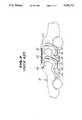
- FIG. 7shows a known lighting system for use in a vehicle cabin.
- a lamp 22such as a room lamp for illuminating a cabin of an automotive vehicle 21 is generally arranged to a roof 23 at its center portion (or in the vicinity of the center portion).
- the lamp 22is constructed in part or in its entirety by a material such as a resin having a diffuse transmission characteristic (see, for example, Japanese Utility Model First (unexamined) Publication No. 54-3759).
- the roof 23has a relatively light area at its center portion or in the vicinity of the lamp 22, and a relatively dark area at its portion distant from the lamp 22 or its peripheral portion.
- the lamp 22When turning on, the lamp 22 provides light in the cabin. This light may reach eyes of a driver 29 after being reflected by a back mirror 28 as indicated by an arrow a in FIG. 7, or directly eyes of a passenger 30 as indicated by an arrow b in FIG. 7, causing glare and/or annoyance which results in difficulty of driving and discomfort. Additionally, the lamp 22 is directly visible from a follower vehicle, that is, light of the lamp 22 may directly reach eyes of a driver or a passenger in the follower vehicle as indicated by an arrow c in FIG. 7, causing glare and/or annoyance.
- the lamp 22is turned off in a general way.
- the full darknessmay cause the driver 29 and the passenger 30, particularly, the latter, not only perception of narrowness but uneasiness in the cabin.
- These phenomenaare also found when the passenger 30 takes a rest.
- the illuminanceis not null in the cabin. This will be understood from the fact that, at night, lighting equipments in a bedroom are kept turned on in part to obtain a reduced level of illuminance (use of a night light), and not turned off in their entirety.
- an object of the present inventionto provide a lighting system for use in a vehicle cabin which is free from glare and/or annoyance, and makes easy and calm a driver and a passenger particularly when taking a rest.
- a lighting systemfor use in a cabin of a vehicle, the vehicle having a roof, a floor, a front seat cushion, a rear seat cushion and a seat occupant, the lighting system comprising:
- a plurality of ceiling lampsarranged between the roof and a plane including an eye point of the seat occupant
- At least one first foot lamparranged between the top of the front seat cushion and the floor, said at least one first foot lamp being disposed opposite to the front seat cushion;
- At least one second foot lamparranged between the bottom of the rear seat cushion and the floor;
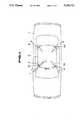
- FIG. 1is a plan view illustrating a preferred embodiment of a lighting system for use in a vehicle cabin according to the present invention
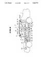
- FIG. 2is a side view illustrating the lighting system in FIG. 1, with a driver and a passenger;
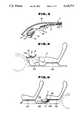
- FIG. 3is a fragmentary section illustrating a ceiling lamp arranged to a roof, taken along the line Y--Y' in FIG. 1;
- FIG. 4is a fragmentary section illustrating a foot lamp arranged to an instrument lower panel
- FIG. 5is a fragmentary section illustrating a foot lamp arranged to be adjacent to a rear seat cushion
- FIG. 6is a luminance distribution characteristic of the roof obtained by the lighting system in FIG. 1;
- FIG. 7is a view similar to FIG. 2, illustrating a known lighting system for use in a vehicle cabin.
- FIGS. 1 to 6a preferred embodiment of a lighting system for use in a vehicle cabin according to the present invention will be described.
- FIGS. 1 and 2in a cabin of an automotive vehicle 1, four ceiling lamps 6 are arranged to a roof 5 at its peripheral portions 5a and 5b on the side of a front seat cushion 2a, and its peripheral portions 5c and 5d on the side of a rear seat cushion 2b so as to be above a plane X including an eye point Ea of a driver 3 seated on the front seat 2a and an eye point Eb of a passenger 4 seated on the rear seat 2b.
- a foot lamp 10ais arranged to an instrument lower cover 9 at its lower portion, which is a vehicle component located in front of the front seat cushion 2a, to be between the top 7 of the front seat cushion 2a and a floor 8a, i.e., within Ha, while a foot lamp 10b is arranged to be adjacent to the rear seat cushion 2b and between the bottom 11 of the rear seat cushion 2b and a floor 8b, i.e., within Hb.
- FIG. 3shows a fragmentary section illustrating one of the ceiling lamps 6 arranged to the roof 5, taken along the line Y--Y' in FIG. 1.
- the ceiling lamp 6is received in a space defined by the roof 5 and an outer roof panel 12 without protruding from the roof 5, so that a high luminance portion which corresponds to principally a bulb 13 is not visible directly from a position of each of the eye points Ea and Eb in the cabin.
- the ceiling lamp 6is received in a space defined by the roof 5 and the outer panel 12 without protruding from the roof 5.
- a wide and effective use of a space in the cabincan be attained by receiving the ceiling lamps 6 in such a manner.
- the ceiling lamp 6includes a reflecting plate 14 which has its function to control an orientation of light so as to illuminate the roof 5 only.
- FIG. 4shows a fragmentary section illustrating the foot lamp 10a arranged to the instrument lower panel 9.
- the foot lamp 10aincludes a bulb 15, and a reflecting plate 16.
- the reflecting plate 16has its function to provide light to the front seat cushion 2a, and control an orientation of light so as to illuminate the floor 8a, and not an area above the top 7 of the front seat cushion 2a.
- FIG. 5shows a fragmentary section illustrating the foot lamp 10b arranged to be adjacent to the rear seat cushion 2b.
- the foot lamp 10bincludes a bulb 17, and a reflecting plate 18.
- the reflecting plate 18has its function to provide light to the front seat cushion 2a, and control an orientation of light so as to illuminate the floor 8b, and not an area above the bottom 11 of the rear seat cushion 2b.
- a high-luminance portion which corresponds to principally the bulb 15 or 17is not visible directly from the position of each of the eye points Ea and Eb in the cabin.
- the ceiling lamps 6 and the foot lamps 10a, 10bare connected to a power supply 20 through a lighting control 19 for turning on and off the lamps 6, 10a and 10b at a desired time.
- the driver 3can change, if necessary, a lighting level or set mode of the ceiling lamps 6 and the foot lamps 10a, 10b by a set mode selector switch 19a.
- the passenger 4can also carry out the same operation by a set mode selector switch 19b.
- the driver 3 or the passenger 4establishes the set mode to "normal" by the set mode selector switch 19a or 19b.
- the luminance of the roof 5is set to be between 90 and 200 cd/m 2 at the peripheral portions 5a, 5b, 5c and 5d of the roof 5, and between 0.1 and 0.5 cd/m 2 at center portions 5e of the roof 5.
- the luminance ratio of the peripheral portions 5a, 5b, 5c and 5d to the center portions 5eis set to be 10:1 or more. In that event, the illuminance of the roof 5 is determined in accordance with its material and reflectance.
- FIG. 6shows a luminance distribution characteristic of the roof 5 obtained by an experience.
- the driver 3 and the passenger 4can feel the roof 5 to be wide by arranging the ceiling lamps 6 to the roof 5 at the peripheral portions 5a, 5b, 5c and 5d so as to make lighter the peripheral portions 5a, 5b, 5c and 5d relative to the center portions 5e.
- the luminance ratio of a visual object or main object to be seen on a desk to a periphery thereofis 10:1 or less, ideally, 3:1 or less (see Lighting Handbook, p. 252, Table 11.2 edited by Lighting Society in Japan). This luminance ratio may be sufficient to obtain a substantially agreeable working environment.
- the luminance ratio of 10:1 or moreis allowable if the driver 3 or the passenger 4 fails to feel discomfort due to absence of visual working to be performed continuously as the office.
- the luminance ratiois set to be 10:1 or more in this embodiment. This results in perception of extent in the cabin in a similar manner as described above.
- a desired value of the average luminance of the roadis approximately between 1 and 2 cd/m 2 (see Lighting Handbook, p. 260, ⁇ 11.4.3 edited by Lighting Society in Japan).
- the driver 3 or the passenger 4 in the vehicle 1adapts to the environment thereof or the brightness of a surface of the road, etc., that is, the eyes of the driver 3 or the passenger 4 get used to the brightness of the environment.
- the luminance of the ceiling lamps 6, principally, the bulbs 13,is approximately 2,000 cd/m 2 in that state, the driver 3 or the passenger 4 feels glare and/or annoyance (see Lighting Handbook, p. 255, Table 11.19 edited by Lighting Society in Japan).
- the luminance ratio of Lc to Llis, for example, approximately 1:10 (see Lighting Handbook, p. 253, Table 11.15 edited by Lighting Society in Japan). This is also applicable to the relationship between the roof 5 and the ceiling lamps 6 mounted thereto in the cabin.
- the value of 0.1 cd/m 2 or moreresults from an experience for obtaining the critical value of luminance which allows perception of depth and extent of the roof 5 as shown in FIG. 6.
- the luminance of the foot lamp 10a for illuminating the floor 8ais set to be 2 cd/m 2 or less in a view range when looking at the floor 8a from the eye point Ea of the driver 3 seated on the front seat cushion 2a, i.e., in a range between the front seat cushion 2a and the instrument lower cover 9, while the luminance of the foot lamp 10b for illuminating the floor 8b is set to be 2 cd/m 2 or less in a view range when looking at the floor 8b from the eye point Eb of the passenger 4 seated on the rear seat cushion 2b, i.e., in a range between the rear seat cushion 2b and the front seat cushion 2a.
- the illuminance of each of the floors 8a and 8bis determined in accordance with its material and reflectance.
- the value of 2 cd/m 2 or lessresults from adaptation of the eyes of the driver 3 or the passenger 4 in a similar manner to the ceiling lamps 6.
- the driver 3 and the passenger 4can feel the floors 8a and 8b to be wide by arranging the foot lamp 10a to the instrument lower cover 9 at its lower portion, and the foot lamp 10b to be adjacent the rear seat cushion 2b for illuminating the floors 8a and 8b.
- the driver 3 or the passenger 4perceives the extent in the cabin in a manner as described above. In that event, the lighting level or set mode in the cabin is established to "normal".
- the driver 3 or the passenger 4When the driver 3 or the passenger 4 takes a rest during normal run or standstill of the vehicle 1, the driver 3 or the passenger 4 establishes the set mode to "rest" by the set mode selector switch 19a or 19b.
- the luminance of the roof 5is set to be 2 cd/m 2 or less at the peripheral portions 5a, 5b, 5c and 5d of the roof 5, and 0.001 cd/m 2 or more at the center portions 5e of the roof 5, reducing the lighting level relative to "normal" mode, respectively.
- the luminance ratio of the peripheral portions 5a, 5b, 5c and 5d to the center portions 5eis set to be 10:1 or more. In that event, the illuminance of the roof 5 is determined in accordance with its material and reflectance.
- the luminance of the foot lamp 10a for illuminating the floor 8ais set to be between 0.01 and 0.05 cd/m 2 in the view range when looking at the floor 8a from the eye point Ea of the driver 3 seated on the front seat cushion 2a, i.e., in the range between the front seat cushion 2a and the instrument lower cover 9, while the luminance of the foot lamp 10b for illuminating the floor 8b is set to be between 0.01 and 0.05 cd/m 2 in the view range when looking at the floor 8b from the eye point Eb of the passenger 4 seated on the rear seat cushion 2b, i.e., in the range between the rear seat cushion 2b and the front seat cushion 2a.
- the illuminance of each of the floors 8a and 8bis determined in accordance with its material and reflectance.
- each eyeWhen identifying and recognizing shape and color of an object, each eye adjusts its lens function to obtain an image at the center of an orbit positioned on a retina and having concentrated conical cells, which operates upon minute observation. It is generally known that the conical cells are low in sensibility, and merely responsive to a light object.
- the eyeshave a high sensibility in a dark environment, and are responsive to an object having luminance of 0.001 cd/m 2 or more in that event.
- the eyesOn the other hand, the eyes have a low sensibility in a light environment, and are merely responsive to an object having higher luminance (see Lighting Handbook, p. 42, ⁇ 3.4 edited by Lighting Society in Japan). Thus, the eyes are generally focused on a lighter object without trying to watch the other one consciously.
- the lighting level in "rest” modemay be about one hundredth (1/100) of that one in "normal” mode so as to obtain the brightness which allows somehow perception of extent on the roof 5, and the shape of an object on the floors 8a and 8b.
- the ceiling lamps 6 and the foot lamps 10a, 10bare turned on with a reduced lighting level in such a manner. Accordingly, the full darkness which may cause the driver 3 or the passenger 4 uneasiness in the cabin can be avoided, resulting in provision of easiness and calmness to the driver 3 or the passenger 4.
- the driver 3 or the passenger 4manually operates the set mode selector switch 19a or 19b to change the set mode from "normal” to "rest", thus obtaining reduced lighting levels of the ceiling lamps 6 and the foot lamps 10a, 10b relative to the normal lighting levels.
- a signal from a sensor, etc.may be used to change the set mode from "normal” to "rest", and vice versa.
Landscapes
- Engineering & Computer Science (AREA)
- Mechanical Engineering (AREA)
- Arrangements Of Lighting Devices For Vehicle Interiors, Mounting And Supporting Thereof, Circuits Therefore (AREA)
Abstract
Description
Claims (9)
Applications Claiming Priority (2)
| Application Number | Priority Date | Filing Date | Title |
|---|---|---|---|
| JP2-253448 | 1990-09-21 | ||
| JP2253448AJPH0813619B2 (en) | 1990-09-21 | 1990-09-21 | Vehicle interior lighting |
Publications (1)
| Publication Number | Publication Date |
|---|---|
| US5226711Atrue US5226711A (en) | 1993-07-13 |
Family
ID=17251543
Family Applications (1)
| Application Number | Title | Priority Date | Filing Date |
|---|---|---|---|
| US07/761,054Expired - LifetimeUS5226711A (en) | 1990-09-21 | 1991-09-18 | Lighting system for use in vehicle cabin |
Country Status (2)
| Country | Link |
|---|---|
| US (1) | US5226711A (en) |
| JP (1) | JPH0813619B2 (en) |
Cited By (12)
| Publication number | Priority date | Publication date | Assignee | Title |
|---|---|---|---|---|
| DE9313534U1 (en)* | 1993-09-08 | 1993-11-18 | FER Fahrzeugelektrik GmbH, 99817 Eisenach | Interior for a motor vehicle |
| GB2343214A (en)* | 1998-11-02 | 2000-05-03 | Bayerische Motoren Werke Ag | Vehicle sunroof having an artificial electric light source arranged between inner and outer panes |
| DE19920404A1 (en)* | 1999-05-04 | 2000-11-09 | Hella Innenleuchten Systeme Gm | Lamp, e.g. for vehicle interior; has line or curve of photodiodes and reflector with shallow area nearer photodiode and steep area further from photodiode, to reflect part of beam from both areas |
| US6179453B1 (en)* | 1999-10-29 | 2001-01-30 | Ford Global Technologies, Inc. | Selective zonal courtesy lamps for automotive vehicle |
| US6621225B2 (en) | 1998-10-09 | 2003-09-16 | Frederick J. Bruwer | Intelligent electrical switching devices |
| US20040021427A1 (en)* | 2000-06-13 | 2004-02-05 | Bruwer Frederick Johannes | Intelligent switch for connecting power to a load |
| US20040062054A1 (en)* | 2002-09-26 | 2004-04-01 | Alan Sturt | Vehicle interior lighting |
| US20040217655A1 (en)* | 1998-10-09 | 2004-11-04 | Bruwer Frederick Johannes | Intelligent electrical devices |
| DE102007001702A1 (en)* | 2007-01-11 | 2008-07-17 | Airbus Deutschland Gmbh | Lighting device for an aircraft |
| CN104837682A (en)* | 2012-12-13 | 2015-08-12 | 日产自动车株式会社 | interior lighting |
| CN107709094A (en)* | 2015-10-29 | 2018-02-16 | 宝马股份公司 | Motor vehicle |
| US10427599B2 (en) | 2015-02-23 | 2019-10-01 | Coelux S.R.L. | Seat illuminating system |
Families Citing this family (4)
| Publication number | Priority date | Publication date | Assignee | Title |
|---|---|---|---|---|
| JP4290518B2 (en)* | 2003-10-08 | 2009-07-08 | トヨタ車体株式会社 | Automotive instrument panel |
| JP6220356B2 (en)* | 2015-01-23 | 2017-10-25 | 矢崎総業株式会社 | Car interior lighting system |
| JP7046439B2 (en)* | 2018-05-08 | 2022-04-04 | アルパイン株式会社 | Vehicle interior lighting control device |
| JP7230726B2 (en)* | 2019-07-26 | 2023-03-01 | 豊田合成株式会社 | Vehicle lighting device |
Citations (22)
| Publication number | Priority date | Publication date | Assignee | Title |
|---|---|---|---|---|
| US2337794A (en)* | 1940-08-02 | 1943-12-28 | Patent License Corp | Lighting equipment |
| US2582738A (en)* | 1949-07-08 | 1952-01-15 | Patent License Corp | Interior illumination system for vehicles and recessed twin beam fixtures therefor |
| US2635681A (en)* | 1950-03-16 | 1953-04-21 | American Seating Co | Seat and aisle lighting |
| GB818525A (en)* | 1956-02-15 | 1959-08-19 | John Henry Marriott | Improvements in combined smokers' ash-trays and electric lamps |
| JPS543759A (en)* | 1977-06-10 | 1979-01-12 | Hitachi Ltd | Machine hand |
| US4139801A (en)* | 1977-01-26 | 1979-02-13 | Linares Raul F | Automatic automobile light control system |
| US4142227A (en)* | 1977-05-23 | 1979-02-27 | Gulton Industries, Inc. | Combination passenger reading light and air ventilator |
| US4217628A (en)* | 1978-04-03 | 1980-08-12 | Windom Kenneth R | Electrical lighting system for rotating chair |
| US4236101A (en)* | 1978-08-18 | 1980-11-25 | Lutron Electronics Co., Inc. | Light control system |
| JPS57144143A (en)* | 1981-02-28 | 1982-09-06 | Tachikawa Spring Co Ltd | Vehicle seat |
| US4368406A (en)* | 1980-12-29 | 1983-01-11 | Ford Motor Company | Lamp dimmer control with integral ambient sensor |
| JPS59145638A (en)* | 1983-01-07 | 1984-08-21 | Omron Tateisi Electronics Co | Dimming indoor lighting system |
| JPS61193945A (en)* | 1985-02-25 | 1986-08-28 | Nissan Motor Co Ltd | Vehicle interior light on/off control device |
| US4670819A (en)* | 1985-08-06 | 1987-06-02 | Prince Corporation | Interior vehicle light |
| US4695769A (en)* | 1981-11-27 | 1987-09-22 | Wide-Lite International | Logarithmic-to-linear photocontrol apparatus for a lighting system |
| US4823239A (en)* | 1983-07-07 | 1989-04-18 | Gateway Industries, Inc. | Seat retractor with lighting means |
| US4866345A (en)* | 1986-10-31 | 1989-09-12 | Nissan Motor Co., Ltd. | Vehicle interior lamp shut-off device with particular dimming sequence |
| EP0342345A2 (en)* | 1988-05-18 | 1989-11-23 | Wolfgang Dipl.-Ing. Priesemuth | Interior light for a motor vehicle |
| JPH0328038A (en)* | 1989-06-26 | 1991-02-06 | Nissan Motor Co Ltd | Car-interior illumination device |
| US5047688A (en)* | 1990-06-11 | 1991-09-10 | Siegel-Robert, Inc. | Automobile interior light control system |
| US5143437A (en)* | 1989-06-26 | 1992-09-01 | Nissan Motor Company, Limited | Vehicle room illuminating apparatus |
| US5149187A (en)* | 1990-09-21 | 1992-09-22 | Nissan Motor Co., Ltd. | Lighting system for use in vehicle cabin |
Family Cites Families (8)
| Publication number | Priority date | Publication date | Assignee | Title |
|---|---|---|---|---|
| JPS5836599U (en)* | 1981-09-03 | 1983-03-09 | 三菱電機株式会社 | Lighting lamp dimming circuit |
| JPS5846595A (en)* | 1981-09-14 | 1983-03-18 | 市光工業株式会社 | Automotive room lamp control device |
| JPS5975600A (en)* | 1982-10-22 | 1984-04-28 | 株式会社三陽電機製作所 | Fluorescent lamp firing circuit capable of dimming |
| JPS6043452U (en)* | 1983-08-26 | 1985-03-27 | トヨタ自動車株式会社 | Storage device with lighting window that can be replaced with an ashtray |
| JPS61189859U (en)* | 1985-05-20 | 1986-11-26 | ||
| JPH0349948Y2 (en)* | 1985-05-29 | 1991-10-24 | ||
| JPS63189835U (en)* | 1987-05-28 | 1988-12-06 | ||
| JPS6415542U (en)* | 1987-07-14 | 1989-01-26 |
- 1990
- 1990-09-21JPJP2253448Apatent/JPH0813619B2/ennot_activeExpired - Fee Related
- 1991
- 1991-09-18USUS07/761,054patent/US5226711A/ennot_activeExpired - Lifetime
Patent Citations (23)
| Publication number | Priority date | Publication date | Assignee | Title |
|---|---|---|---|---|
| US2337794A (en)* | 1940-08-02 | 1943-12-28 | Patent License Corp | Lighting equipment |
| US2582738A (en)* | 1949-07-08 | 1952-01-15 | Patent License Corp | Interior illumination system for vehicles and recessed twin beam fixtures therefor |
| US2635681A (en)* | 1950-03-16 | 1953-04-21 | American Seating Co | Seat and aisle lighting |
| GB818525A (en)* | 1956-02-15 | 1959-08-19 | John Henry Marriott | Improvements in combined smokers' ash-trays and electric lamps |
| US4139801A (en)* | 1977-01-26 | 1979-02-13 | Linares Raul F | Automatic automobile light control system |
| US4142227A (en)* | 1977-05-23 | 1979-02-27 | Gulton Industries, Inc. | Combination passenger reading light and air ventilator |
| JPS543759A (en)* | 1977-06-10 | 1979-01-12 | Hitachi Ltd | Machine hand |
| US4217628A (en)* | 1978-04-03 | 1980-08-12 | Windom Kenneth R | Electrical lighting system for rotating chair |
| US4236101A (en)* | 1978-08-18 | 1980-11-25 | Lutron Electronics Co., Inc. | Light control system |
| US4368406A (en)* | 1980-12-29 | 1983-01-11 | Ford Motor Company | Lamp dimmer control with integral ambient sensor |
| JPS57144143A (en)* | 1981-02-28 | 1982-09-06 | Tachikawa Spring Co Ltd | Vehicle seat |
| US4695769A (en)* | 1981-11-27 | 1987-09-22 | Wide-Lite International | Logarithmic-to-linear photocontrol apparatus for a lighting system |
| JPS59145638A (en)* | 1983-01-07 | 1984-08-21 | Omron Tateisi Electronics Co | Dimming indoor lighting system |
| US4823239A (en)* | 1983-07-07 | 1989-04-18 | Gateway Industries, Inc. | Seat retractor with lighting means |
| JPS61193945A (en)* | 1985-02-25 | 1986-08-28 | Nissan Motor Co Ltd | Vehicle interior light on/off control device |
| US4670819A (en)* | 1985-08-06 | 1987-06-02 | Prince Corporation | Interior vehicle light |
| US4866345A (en)* | 1986-10-31 | 1989-09-12 | Nissan Motor Co., Ltd. | Vehicle interior lamp shut-off device with particular dimming sequence |
| EP0342345A2 (en)* | 1988-05-18 | 1989-11-23 | Wolfgang Dipl.-Ing. Priesemuth | Interior light for a motor vehicle |
| US5130901A (en)* | 1988-05-18 | 1992-07-14 | Priesemuth W | Electric light switching arrangement for illuminating the interior of a motor vehicle |
| JPH0328038A (en)* | 1989-06-26 | 1991-02-06 | Nissan Motor Co Ltd | Car-interior illumination device |
| US5143437A (en)* | 1989-06-26 | 1992-09-01 | Nissan Motor Company, Limited | Vehicle room illuminating apparatus |
| US5047688A (en)* | 1990-06-11 | 1991-09-10 | Siegel-Robert, Inc. | Automobile interior light control system |
| US5149187A (en)* | 1990-09-21 | 1992-09-22 | Nissan Motor Co., Ltd. | Lighting system for use in vehicle cabin |
Non-Patent Citations (9)
| Title |
|---|
| "Adjustment of Luminance in Living Room", Meeting of Union of Kansai Branches of Electric and Related Societies, by Sotaro Matsuda, 1966. |
| "Report of Fundamental Research on How Guide Lamp is Seen", Lighting Society of Japan, 1984. |
| 07/761,052 patent pending Matsuno et al.* |
| 07/761,056 patent pending Matsuno et al.* |
| 07/892,302 patent pending Asada et al.* |
| Adjustment of Luminance in Living Room , Meeting of Union of Kansai Branches of Electric and Related Societies, by Sotaro Matsuda, 1966.* |
| Lighting Handbook, pp. 42 44, 252, 253, 255, 260 261, 267, 430 and 431.* |
| Lighting Handbook, pp. 42-44, 252, 253, 255, 260-261, 267, 430 and 431. |
| Report of Fundamental Research on How Guide Lamp is Seen , Lighting Society of Japan, 1984.* |
Cited By (40)
| Publication number | Priority date | Publication date | Assignee | Title |
|---|---|---|---|---|
| DE9313534U1 (en)* | 1993-09-08 | 1993-11-18 | FER Fahrzeugelektrik GmbH, 99817 Eisenach | Interior for a motor vehicle |
| US7336037B2 (en) | 1998-10-09 | 2008-02-26 | Azoteq Pty Ltd. | Intelligent electrical switching device |
| US7084531B2 (en) | 1998-10-09 | 2006-08-01 | Azoteq (Pty) Ltd | Intelligent electrical devices |
| US8823273B2 (en) | 1998-10-09 | 2014-09-02 | Global Touch Solutions, Llc | Intelligent user interface including a touch sensor device |
| US8531120B2 (en) | 1998-10-09 | 2013-09-10 | Azoteq Pty Ltd. | Intelligent user interface including a touch sensor device |
| US6621225B2 (en) | 1998-10-09 | 2003-09-16 | Frederick J. Bruwer | Intelligent electrical switching devices |
| US6650066B2 (en) | 1998-10-09 | 2003-11-18 | Frederick J. Bruwer | Intelligent electrical switching device |
| US8288952B2 (en) | 1998-10-09 | 2012-10-16 | Azoteq Pty Ltd. | Intelligent user interface including a touch sensor device |
| US7994726B2 (en) | 1998-10-09 | 2011-08-09 | Azoteq Pty Ltd. | Intelligent user interface including a touch sensor device |
| US20040080274A1 (en)* | 1998-10-09 | 2004-04-29 | Bruwer Frederick J. | Intelligent electrical switching device |
| US20040217655A1 (en)* | 1998-10-09 | 2004-11-04 | Bruwer Frederick Johannes | Intelligent electrical devices |
| US20040227409A1 (en)* | 1998-10-09 | 2004-11-18 | Bruwer Frederick Johannes | Intelligent electrical devices |
| US20050140310A1 (en)* | 1998-10-09 | 2005-06-30 | Bruwer Frederick J. | Intelligent electrical switching device |
| US6952084B2 (en) | 1998-10-09 | 2005-10-04 | Azoteq Pty Ltd. | Intelligent electrical switching device |
| US7781980B2 (en) | 1998-10-09 | 2010-08-24 | Azoteq Pty Ltd. | Intelligent user interface including a touch sensor device |
| US6984900B1 (en) | 1998-10-09 | 2006-01-10 | Azoteq (Pty) Ltd. | Intelligent electrical switch |
| US7498749B2 (en) | 1998-10-09 | 2009-03-03 | Azoteq Pty Ltd. | Intelligent electrical switching device including a touch sensor user interface switch |
| US20080048574A1 (en)* | 1998-10-09 | 2008-02-28 | Bruwer Frederick J | Intelligent Electrical Switching Device |
| US7084526B2 (en) | 1998-10-09 | 2006-08-01 | Azoteq (Pty) Ltd | Intelligent electrical devices |
| US20080094002A1 (en)* | 1998-10-09 | 2008-04-24 | Azoteg Pty Ltd. | Intelligent Electrical Switching Device |
| US7443101B2 (en) | 1998-10-09 | 2008-10-28 | Azoteq Pty Ltd. | Intelligent electrical switching device including a touch sensor switch |
| GB2343214B (en)* | 1998-11-02 | 2003-02-19 | Bayerische Motoren Werke Ag | Vehicle roof extension with variable transparency pane |
| GB2343214A (en)* | 1998-11-02 | 2000-05-03 | Bayerische Motoren Werke Ag | Vehicle sunroof having an artificial electric light source arranged between inner and outer panes |
| DE19920404A1 (en)* | 1999-05-04 | 2000-11-09 | Hella Innenleuchten Systeme Gm | Lamp, e.g. for vehicle interior; has line or curve of photodiodes and reflector with shallow area nearer photodiode and steep area further from photodiode, to reflect part of beam from both areas |
| US6179453B1 (en)* | 1999-10-29 | 2001-01-30 | Ford Global Technologies, Inc. | Selective zonal courtesy lamps for automotive vehicle |
| US7119459B2 (en) | 2000-06-13 | 2006-10-10 | Azoteq (Pty) Ltd | Intelligent switch for connecting power to a load |
| US20040021427A1 (en)* | 2000-06-13 | 2004-02-05 | Bruwer Frederick Johannes | Intelligent switch for connecting power to a load |
| US6974238B2 (en) | 2002-09-26 | 2005-12-13 | Lear Corporation | Trim component with mounted light source for indirectly lighting the interior of a vehicle |
| US20040062054A1 (en)* | 2002-09-26 | 2004-04-01 | Alan Sturt | Vehicle interior lighting |
| DE10344824B4 (en)* | 2002-09-26 | 2006-07-20 | Lear Corp., Southfield | Threshold plate with vehicle interior lighting |
| DE102007001702B4 (en)* | 2007-01-11 | 2010-04-08 | Airbus Deutschland Gmbh | Lighting device of an aircraft |
| US8322880B2 (en) | 2007-01-11 | 2012-12-04 | Airbus Operations Gmbh | Illumination device for an aircraft |
| US20100091506A1 (en)* | 2007-01-11 | 2010-04-15 | Airbus Operations Gmbh | Illumination device for an aircraft |
| DE102007001702A1 (en)* | 2007-01-11 | 2008-07-17 | Airbus Deutschland Gmbh | Lighting device for an aircraft |
| CN104837682A (en)* | 2012-12-13 | 2015-08-12 | 日产自动车株式会社 | interior lighting |
| EP2933146A4 (en)* | 2012-12-13 | 2016-01-20 | Nissan Motor | VEHICLE INTERIOR LIGHTING DEVICE |
| US9517722B2 (en) | 2012-12-13 | 2016-12-13 | Nissan Motor Co., Ltd. | Vehicle interior illumination device |
| CN104837682B (en)* | 2012-12-13 | 2018-02-13 | 日产自动车株式会社 | interior lighting |
| US10427599B2 (en) | 2015-02-23 | 2019-10-01 | Coelux S.R.L. | Seat illuminating system |
| CN107709094A (en)* | 2015-10-29 | 2018-02-16 | 宝马股份公司 | Motor vehicle |
Also Published As
| Publication number | Publication date |
|---|---|
| JPH0813619B2 (en) | 1996-02-14 |
| JPH04129856A (en) | 1992-04-30 |
Similar Documents
| Publication | Publication Date | Title |
|---|---|---|
| US5226711A (en) | Lighting system for use in vehicle cabin | |
| US5206562A (en) | Lighting system for use in vehicle cabin | |
| US5149187A (en) | Lighting system for use in vehicle cabin | |
| US6447132B1 (en) | Day/night HUD backlighting system | |
| US20030002165A1 (en) | System and method for vision enhancement in a vehicle | |
| US20080112175A1 (en) | Transitional lighting system for vehicle interior | |
| JPH0328034A (en) | Vehicle interior lighting system | |
| US6598982B2 (en) | Rearview mirror alignment device | |
| US20020189881A1 (en) | System and method for enhancing vision in a vehicle | |
| JP2525481B2 (en) | Vehicle interior lighting | |
| JP2010076519A (en) | Compartment lighting system | |
| GB2553337A (en) | Dome light assembly for a vehicle, cabin for a vehicle comprising a dome light assembly, and vehicle comprising a cabin with a dome light assembly | |
| JPH10244876A (en) | License plate lamp | |
| JPH05229385A (en) | Vehicle interior lighting | |
| US9517722B2 (en) | Vehicle interior illumination device | |
| US5254907A (en) | Lighting system for use in vehicle cabin | |
| JPH0818513B2 (en) | Vehicle interior lighting | |
| EP1244572A1 (en) | System and method for vision enhancement in a vehicle | |
| JP2603954Y2 (en) | Car interior lights | |
| JPH0328036A (en) | Car-interior illumination device | |
| JPH0328033A (en) | Vehicle interior lighting system | |
| KR20180130757A (en) | Automotive sun visor lighting system | |
| JPH0813621B2 (en) | Vehicle interior lighting | |
| JPH0780432B2 (en) | Vehicle interior lighting | |
| CA1318644C (en) | Illuminated picture frame |
Legal Events
| Date | Code | Title | Description |
|---|---|---|---|
| AS | Assignment | Owner name:MATSUSHITA ELECTRIC INDUSTRIAL CO., LTD. Free format text:ASSIGNMENT OF ASSIGNORS INTEREST.;ASSIGNORS:OKAMURA, IZUMI;SHIGETA, TERUAKI;TANABE, YOSHINORI;REEL/FRAME:005953/0922 Effective date:19911015 Owner name:NISSAN MOTOR CO., LTD. Free format text:ASSIGNMENT OF ASSIGNORS INTEREST.;ASSIGNORS:OKAMURA, IZUMI;SHIGETA, TERUAKI;TANABE, YOSHINORI;REEL/FRAME:005953/0922 Effective date:19911015 Owner name:MATSUSHITA ELECTRIC INDUSTRIAL CO., LTD. Free format text:ASSIGNMENT OF ASSIGNORS INTEREST.;ASSIGNORS:MATSUNO, YOSHIO;MATSUI, HITOSHI;REEL/FRAME:005953/0925 Effective date:19911016 Owner name:NISSAN MOTOR CO., LTD. Free format text:ASSIGNMENT OF ASSIGNORS INTEREST.;ASSIGNORS:MATSUNO, YOSHIO;MATSUI, HITOSHI;REEL/FRAME:005953/0925 Effective date:19911016 | |
| FEPP | Fee payment procedure | Free format text:PAYOR NUMBER ASSIGNED (ORIGINAL EVENT CODE: ASPN); ENTITY STATUS OF PATENT OWNER: LARGE ENTITY | |
| STCF | Information on status: patent grant | Free format text:PATENTED CASE | |
| FPAY | Fee payment | Year of fee payment:4 | |
| FPAY | Fee payment | Year of fee payment:8 | |
| FPAY | Fee payment | Year of fee payment:12 |