US5226281A - Z-tab innerseal for a container and method of application - Google Patents
Z-tab innerseal for a container and method of applicationDownload PDFInfo
- Publication number
- US5226281A US5226281AUS07/809,839US80983991AUS5226281AUS 5226281 AUS5226281 AUS 5226281AUS 80983991 AUS80983991 AUS 80983991AUS 5226281 AUS5226281 AUS 5226281A
- Authority
- US
- United States
- Prior art keywords
- innerseal
- layer
- sealing
- container
- bonding
- Prior art date
- Legal status (The legal status is an assumption and is not a legal conclusion. Google has not performed a legal analysis and makes no representation as to the accuracy of the status listed.)
- Expired - Fee Related
Links
Images


Classifications
- B—PERFORMING OPERATIONS; TRANSPORTING
- B65—CONVEYING; PACKING; STORING; HANDLING THIN OR FILAMENTARY MATERIAL
- B65D—CONTAINERS FOR STORAGE OR TRANSPORT OF ARTICLES OR MATERIALS, e.g. BAGS, BARRELS, BOTTLES, BOXES, CANS, CARTONS, CRATES, DRUMS, JARS, TANKS, HOPPERS, FORWARDING CONTAINERS; ACCESSORIES, CLOSURES, OR FITTINGS THEREFOR; PACKAGING ELEMENTS; PACKAGES
- B65D77/00—Packages formed by enclosing articles or materials in preformed containers, e.g. boxes, cartons, sacks or bags
- B65D77/10—Container closures formed after filling
- B65D77/20—Container closures formed after filling by applying separate lids or covers, i.e. flexible membrane or foil-like covers
- B65D77/2024—Container closures formed after filling by applying separate lids or covers, i.e. flexible membrane or foil-like covers the cover being welded or adhered to the container
- B65D77/2028—Means for opening the cover other than, or in addition to, a pull tab
- B65D77/2032—Means for opening the cover other than, or in addition to, a pull tab by peeling or tearing the cover from the container
- B65D77/2044—Means for opening the cover other than, or in addition to, a pull tab by peeling or tearing the cover from the container whereby a layer of the container or cover fails, e.g. cohesive failure
- B—PERFORMING OPERATIONS; TRANSPORTING
- B65—CONVEYING; PACKING; STORING; HANDLING THIN OR FILAMENTARY MATERIAL
- B65D—CONTAINERS FOR STORAGE OR TRANSPORT OF ARTICLES OR MATERIALS, e.g. BAGS, BARRELS, BOTTLES, BOXES, CANS, CARTONS, CRATES, DRUMS, JARS, TANKS, HOPPERS, FORWARDING CONTAINERS; ACCESSORIES, CLOSURES, OR FITTINGS THEREFOR; PACKAGING ELEMENTS; PACKAGES
- B65D77/00—Packages formed by enclosing articles or materials in preformed containers, e.g. boxes, cartons, sacks or bags
- B65D77/10—Container closures formed after filling
- B65D77/20—Container closures formed after filling by applying separate lids or covers, i.e. flexible membrane or foil-like covers
- B65D77/2024—Container closures formed after filling by applying separate lids or covers, i.e. flexible membrane or foil-like covers the cover being welded or adhered to the container
- B65D77/2028—Means for opening the cover other than, or in addition to, a pull tab
- B65D77/2032—Means for opening the cover other than, or in addition to, a pull tab by peeling or tearing the cover from the container
- B65D77/2044—Means for opening the cover other than, or in addition to, a pull tab by peeling or tearing the cover from the container whereby a layer of the container or cover fails, e.g. cohesive failure
- B65D77/2048—Means for opening the cover other than, or in addition to, a pull tab by peeling or tearing the cover from the container whereby a layer of the container or cover fails, e.g. cohesive failure whereby part of the container or cover has been weakened, e.g. perforated or precut
- B65D77/2056—Means for opening the cover other than, or in addition to, a pull tab by peeling or tearing the cover from the container whereby a layer of the container or cover fails, e.g. cohesive failure whereby part of the container or cover has been weakened, e.g. perforated or precut the cover being weakened
- B—PERFORMING OPERATIONS; TRANSPORTING
- B65—CONVEYING; PACKING; STORING; HANDLING THIN OR FILAMENTARY MATERIAL
- B65D—CONTAINERS FOR STORAGE OR TRANSPORT OF ARTICLES OR MATERIALS, e.g. BAGS, BARRELS, BOTTLES, BOXES, CANS, CARTONS, CRATES, DRUMS, JARS, TANKS, HOPPERS, FORWARDING CONTAINERS; ACCESSORIES, CLOSURES, OR FITTINGS THEREFOR; PACKAGING ELEMENTS; PACKAGES
- B65D2251/00—Details relating to container closures
- B65D2251/0003—Two or more closures
- B65D2251/0006—Upper closure
- B65D2251/0015—Upper closure of the 41-type
- B—PERFORMING OPERATIONS; TRANSPORTING
- B65—CONVEYING; PACKING; STORING; HANDLING THIN OR FILAMENTARY MATERIAL
- B65D—CONTAINERS FOR STORAGE OR TRANSPORT OF ARTICLES OR MATERIALS, e.g. BAGS, BARRELS, BOTTLES, BOXES, CANS, CARTONS, CRATES, DRUMS, JARS, TANKS, HOPPERS, FORWARDING CONTAINERS; ACCESSORIES, CLOSURES, OR FITTINGS THEREFOR; PACKAGING ELEMENTS; PACKAGES
- B65D2251/00—Details relating to container closures
- B65D2251/0003—Two or more closures
- B65D2251/0068—Lower closure
- B65D2251/0093—Membrane
- B—PERFORMING OPERATIONS; TRANSPORTING
- B65—CONVEYING; PACKING; STORING; HANDLING THIN OR FILAMENTARY MATERIAL
- B65D—CONTAINERS FOR STORAGE OR TRANSPORT OF ARTICLES OR MATERIALS, e.g. BAGS, BARRELS, BOTTLES, BOXES, CANS, CARTONS, CRATES, DRUMS, JARS, TANKS, HOPPERS, FORWARDING CONTAINERS; ACCESSORIES, CLOSURES, OR FITTINGS THEREFOR; PACKAGING ELEMENTS; PACKAGES
- B65D2577/00—Packages formed by enclosing articles or materials in preformed containers, e.g. boxes, cartons, sacks, bags
- B65D2577/10—Container closures formed after filling
- B65D2577/20—Container closures formed after filling by applying separate lids or covers
- B65D2577/2041—Pull tabs
- B65D2577/205—Pull tabs integral with the closure
Definitions
- This inventionrelates to container innerseals which are used to provide an airtight seal for containers. More specifically, the invention relates to an improved innerseal for a container which is easier to remove, and promotes ease of removal in conjunction with improved sealability for containers on which it is applied relative to those innerseals which were heretofore known.
- the sealis particularly effective for products which should be preferably kept free from contamination, oxidation and/or moisture.
- itis difficult to effectively control the adhesive force by which such innerseals are bonded to the containers, due to the dependency of the sealing force on the amount of inductive power that is applied. Accordingly, it has previously been necessary to maintain strict control over the amount of power that is applied during sealing of such containers, and a wide range of seal tightness may result even if the power range is effectively controlled.
- the amount of sealing force which could be usedwas limited by the fact that an equal amount of force was needed to remove the innerseal from the container by the end user. As a result such seals had to be penetrated or scraped off with a sharp implement such as a knife. This problem was compounded by the inconsistency of sealing forces from container to container and the limitations on sealing force as discussed above.
- an improved container assembly of the type having an innerseal for providing an additional seal between an inner portion thereof and an outside spaceincludes a container having an opening defined therein by an upper rim thereof; a first sealing structure adapted for sealing over a first portion of the upper rim to close a first portion of the opening; a second sealing structure adapted for sealing over a second portion of the upper rim to close a second remaining portion of the opening; and a flap structure positioned between the first and second sealing structures and adapted for gripping by a user, whereby the innerseal may be removed from the container without the aid of a scraping or puncturing tool.
- a method for forming an improved container assemblyincludes the steps of providing a layered material including a lower sealing layer and a fluid passage prevention layer, the layered material being folded over upon itself in a intermediate portion thereof; cutting the layered material in a pattern corresponding to the opening, whereby the folded over portion forms the flap structure; applying the innerseal over the opening defined by the upper rim of the container in such a manner that the first sealing structure covers the first portion of the opening and the second sealing structure covers the second portion of the opening, the flap structure being positioned between the first and second sealing structures in such a manner as to be adapted for grasping by a user; and sealing the first and second pealing structures to the upper rim of the container, whereby the container is covered by an airtight, easy to remove innerseal.
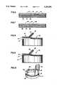
- FIG. 1is a perspective view of an improved container assembly constructed according to the invention
- FIG. 2is a perspective view of an innerseal portion of the embodiment illustrated in FIG. 1;
- FIG. 3is a fragmentary cross-sectional view of a first embodiment of the innerseal illustrated in FIG. 2;
- FIG. 4is a fragmentary cross-sectional view of a second embodiment of the innerseal illustrated in FIG. 2;
- FIG. 5is a fragmentary cross-sectional view of a third embodiment of the innerseal illustrated in FIG. 2;
- FIG. 6is a fragmentary cross-sectional view of a fourth embodiment of the innerseal illustrated in FIG. 2;
- FIG. 7is a fragmentary cross-sectional view of a fifth embodiment of the innerseal illustrated in FIG. 2;
- FIG. 8is a diagrammatical view of an innerseal constructed according to the embodiment of FIG. 3 being removed from the container;
- FIG. 9is a diagrammatical view of an innerseal constructed according to the embodiments of FIGS. 4-6 being removed from the container;
- FIG. 10is a diagrammatical view illustrating an innerseal constructed according to the embodiment depicted in FIG. 7 being removed from the container;
- FIG. 11is a top plan view of a stock material used in forming innerseals according to the invention.
- a container 10includes a neck portion 12 having threads 14 formed therein.
- An openingis defined in container 10 by rim 16, which is formed at an upper extremity of neck portion 12.
- Innerseal 18is mounted so as to seal the opening defined by rim 16, as is shown in FIG. 1.
- Innerseal 18includes a first sealing portion 20 which seals a first portion of the opening, a second sealing portion 22 which seals a remaining second portion of the opening and a fold-over portion 24 which is positioned between the first sealing portion and the second sealing portion 22.
- first sealing portion 20, second sealing portion 22 and fold-over portion 24are all formed from a single continuously extending sheet of common layered material, with fold-over portion 24 including a first flap 26 which is contiguous with first sealing portion 20 and a second flap 28 contiguous with second sealing portion 22.
- First and second flaps 26, 28are preferably formed of a length that is sufficient to enable fold-over portion 24 to be grasped by an end user, so that innerseal 18 may be removed from the container 10.
- fold-over portion 24is disposed in a position parallel to the first and second sealing portions 20, 22, and lies against an upper surface of second sealing portion 22.
- an end usermay insert his or her fingernail between second sealing portion 22 and fold-over portion 24 to lift fold-over portion 24 to the position that is illustrated in FIG. 1. Fold-over portion 24 may then be grasped and removed by the end user.
- Layered material 30includes a bottom sealing layer 32 which is for sealing innerseal 18 onto the rim portion 16 of container 10.
- a metallic layer 36is provided for preventing passage of fluid through layered material 30 and for heating the layered material in response to an induction heater to seal layer 32 onto rim portion 16, as will be below described.
- Metallic layer 36is bonded to sealing layer 32 by a first adhesive layer 34.
- An optional layer 40may be laminated onto a top surface of metallic layer 36 by a second adhesive layer 38 for aesthetic purposes.
- Sealing layer 32is preferably formed of a polymeric film which is between 1 and 1.5 mils in thickness.
- Examples of the materials which may be used to form sealing layer 32are polyethylene, polypropylene, ethylene vinyl acetate, Surlyn brand 1702 resin or a laminate of polyethylene and a 0.5 mil layer of polyester.
- the purpose of sealing layer 32is to be heat bondable to rim 16 with a bonding force which is less than the rupture force of sealing layer 32.
- First adhesive layer 34may be formed of any adhesive capable of bonding the materials discussed above in regard to sealing layer 32 to metallic layer 36, and is preferably formed of Adcote 503A adhesive, which is available from Morton Norwich Products, Inc. of Chicago, Ill.
- Metallic layer 36is preferably formed of aluminum and is in the preferred embodiment between 1-3 mils in thickness.
- Optional layer 40may be formed of any material which might be more aesthetically pleasing than the upper surface of metallic layer 36 or from a material upon which a pattern may be printed, such as a paper or polymeric film.
- Second adhesive layer 38may be formed of any substance capable of bonding metallic layer 36 to optional layer 40, and is preferably composed of Adcote 503A.
- sealing layer 32is formed from a film of ScotchpakTM 113 film having a thickness of between 1-1.5 mils.
- ScotchpakTM 113is formed of ethylene vinyl acetate and 0.5 mil layer of polyester, and is available from the 3M Company of St. Paul, Minn.
- Metallic layer 36is formed from aluminum foil having a thickness of 2 mils which is commercial available from the Aluminum Company of America of Davenport, Iowa.
- First adhesive layer 34is formed of Adcote 503A laminating adhesive. In this sample, second adhesive layer 38 and optional layer 40 are not included.
- sealing layer 32is formed of a ScotchpakTM 113 film having a thickness of between 1-1.5 mils.
- First adhesive layer 34is formed of Adcote 503A laminating adhesive.
- Metallic layer 36is formed of aluminum foil having a thickness of approximately 3 mils. In this sample, optional layer 40 and second adhesive layer 38 are not included.
- sealing layer 32is formed of ScotchpakTM 107 film, which is between 1-1.5 mils in thickness and includes a 0.5 mil layer of polyester and a second layer of polyethylene. ScotchpakTM 107 film is commercially available from the Minnesota Mining and Manufacturing Company of St. Paul, Minn.
- First adhesive layer 34is formed of Adcote 503A laminating adhesive.
- Metallic layer 36is formed of aluminum foil having a thickness of approximately 1 mil. Optional layer 40 and second adhesive layer 38 were not included in this sample.
- sealing layer 32is formed of a film of Surlyn brand 1702 resin having a thickness of approximately 1.5 mils.
- First adhesive layer 34is formed of Adcote 503A adhesive.
- Metallic layer 36is formed of a sheet of aluminum foil having a thickness of approximately 1.5 mils. No optional layer 40 or second adhesive layer 38 were provided in this sample.
- the innersealis provided with a bonding arrangement which has a first bonding portion and a second bonding portion.
- the first bonding portionis designed to bond to rim 16 with a first bonding force which is greater than a second bonding force which bonds the first and second bonding portions together.
- the first bonding portionhas a rupture strength which is less than either the first or second bonding force.
- a third bonding force between the bonding arrangement and the remainder of the innersealis greater than the second bonding force.
- Layered material 42includes a bonding arrangement consisting of a first bonding portion which is embodied as sealing layer 44 and a second bonding portion embodied as adhesive layer 46, which bonds layer 44 to a metallic layer 48.
- An optional layer 52may be bonded to an upper surface of metallic layer 48 by an adhesive layer 50 for aesthetic purposes.
- Sealing layer 44is preferably formed of a polymeric film having a thickness of between 0.5-1.5 mils.
- sealing layer 44Materials which may be used to form sealing layer 44 include polyethylene, polypropylene, ethylene vinyl acetate, Surlyn brand 1702 resin or, polyester of 50 OL-2 Mylar brand film, for use when container 10 is fabricated of PVC.
- Adhesive layer 46may be formed of any adhesive capable of bonding the materials mentioned above in regard to sealing member 44 to a metallic substance, such as Adcote 503A adhesive.
- Metallic layer 48is preferably formed of aluminum or an equivalent material which can be heated inductively and is effective in preventing passage of fluid therethrough.
- Optional layer 52 and adhesive layer 50are formed of materials identical to those discussed above in reference to optional layer 40 and adhesive layer 38 in the embodiment depicted in FIG. 3, respectively.
- sealing layer 44is formed of a sheet of 50 OL-2 Mylar brand film having a thickness of approximately 0.5 mils.
- Adhesive layer 46is preferably formed of Adcote 503A laminating adhesive.
- Metallic layer 48is formed of a sheet of aluminum foil having a thickness of approximately 1 mil. This sample did not include an optional layer 52 or adhesive layer 50.
- a layered material 54 constructed according to a third embodiment of the inventionincludes a bonding arrangement having a first bonding portion embodied as sealing layer 56, a second bonding portion embodied as a layer of pressure sensitive adhesive 58, a primer layer 60, a metallic layer 62, an optional layer 66 and an adhesive layer 64 for bonding optional layer 66 to metallic layer 62.
- Sealing layer 56is preferably formed of a polymeric film such as polyethylene, polypropylene, ethylene vinyl acetate, Surlyn brand 1702 resin or an equivalent material, and is between 1-1.5 mils in thickness.
- Layer 58may be formed out of any suitable pressure sensitive adhesive, such as natural rubber, and is preferably 0.1-0.2 mils in thickness.
- Layer 60which is between 0.01-0.05 mils in thickness, is formed of a suitable primer, such as CP 343-1 primer which is commercially available from the Eastman Chemical Corporation, in Kingsport, Tenn.
- Metallic layer 62is formed of aluminum or a suitable alternative material which can be heated inductively and is effective at preventing passage of fluid therethrough.
- the optional aesthetic layer 66 and adhesive layer 64are formed of materials identical to those discussed above with reference to layers 40, 38, respectively, in the embodiment illustrated in FIG. 3.
- sealing layer 56is formed of a polyethylene film having a thickness of approximately 1 mil.
- Adhesive layer 58is formed of Kraton® elastomeric copolymer, which is commercially available from Shell Chemical Company of Oak Brook, Ill.
- Primer layer 60is formed of Eastman CP-343-1 primer.
- Metallic layer 62is formed of a sheet of aluminum foil having a thickness of approximately 1 mil.
- sealing layer 56is formed of a layer of polyethylene film having a thickness of approximately 1 mil.
- Layer 58is formed of a natural rubber pressure sensitive adhesive having a thickness of 0.1-0.2 mils.
- Layer 60is formed of Eastman CP 343-1 primer and has a thickness of 0.01-0.05 mils.
- Metallic layer 62is formed of a sheet of aluminum foil having a thickness of approximately 1 mil.
- Optional layer 66 and adhesive layer 64were not included in this sample.
- a layered material 67 constructed according to a fourth embodiment of the inventionincludes a bonding arrangement having a first bonding portion embodied as sealing layer 68, a second bonding portion embodied as a layer 70 of pressure sensitive adhesive, a layer 72 of polymeric film, a layer 74 of metallic foil, a layer 76 of adhesive material and an optional layer 78 which may be provided for aesthetic purposes.
- Sealing layer 68is preferably formed of a polymeric film having a thickness of between 1-1.5 mils. Materials which could be used to form sealing layer 68 include polyethylene, polypropylene, ethylene vinyl acetate, Surlyn brand 1702 resin or other known equivalents.
- Layer 70is formed of a pressure-sensitive adhesive such as natural rubber, and has a preferred thickness within the range of 0.1-0.2 mils.
- the layer 72 of polymeric filmis preferably formed of polypropylene or an equivalent material and has a thickness of approximately 1.5 mils.
- Metallic foil 74is preferably made of aluminum and may have a thickness of approximately 1-3 mils.
- Adhesive layer 76 and optional layer 78are preferably formed of the same materials discussed above in reference to adhesive layer 38 and optional layer 40 in the embodiment illustrated in FIG. 3.
- An example of layered material 67which has been constructed and has proven satisfactory will now be detailed:
- sealing layer 68is formed of polyethylene and has a thickness of approximately 1 mil.
- Layer 70is formed of natural rubber pressure sensitive adhesive, and has a thickness of approximately 0.1-0.2 mils.
- the layer 72 of polymeric film and layer 74 of metallic foilare formed of a commercially available laminate which is available from Aluminum Company of America, Alcoa Center, Pa.
- Layer 72is formed of polypropylene and has a thickness of approximately 1.5 mils.
- Metallic foil 74is formed as a sheet of aluminum foil having a thickness of approximately 1 mil.
- Adhesive layer 76 and optional layer 78were not included in this sample.
- Layered material 80includes a sealing layer 82, an adhesive layer 84, a layer 86 of metallic foil, an optional aesthetic layer 90 and an adhesive layer 88 for bonding optional layer 90 to metallic foil 86 if needed.
- Sealing layer 82is preferably formed of a polymeric film having a thickness of approximately 1-1.5 mils. This embodiment is characterized by an exceptionally strong bond between sealing layer 82 and container 10, which may be created by applying more heat during the sealing process than is applied in the previously described embodiments.
- Materials which may be used to form sealing layer 82include polyethylene, polypropylene, ethylene vinyl acetate, Surlyn brand 1702 resin or an equivalent material.
- Adhesive layer 84may be formed of any known adhesive capable of bonding one of the materials listed above in reference to sealing layer 82 to a layer of metallic foil, such as Adcote 503A laminating adhesive.
- Metallic foil 86is preferably formed of aluminum or an equivalent material which may be heated inductively and is effective in preventing passage of fluid therethrough.
- Optional layer 90 and adhesive layer 88are constructed according to the same materials discussed above with reference to optional layer 40 and adhesive layer 38 in the embodiment illustrated in FIG. 3. 1 mil. In this sample, optional layer 90 and adhesive layer 88 are not included.
- the edge 94 of the sealing layer which is bonded to rim portion 16will delaminate from the second bonding portion of the innerseal and then rupture embodiment illustrated in FIG. 5, this means that the bond between sealing layer 56 and rim portion 16 must be stronger than the bond between the layer 58 of pressure sensitive adhesive and sealing layer 56.
- the edge 94 of the sealing layer which is bonded to rim portion 16will delaminate from the second bonding portion of the innerseal and then rupture apart from the remainder of the sealing layer, leaving a deposit of the sealing layer around the rim portion 16 of the container when innerseal 18 has been removed.
- sealing layer 82is bonded to container 10 with a greater bonding force than is the case with the embodiments of FIGS. 3-6.
- the bond between sealing layer 82 and the rim portion 16 of container 10is stronger than the tear strength of layered material 90.
- layered material 90will tear along a first edge 102 that is substantially parallel to the folded seam of fold-over portion 24, and second and third tear edges 98, 104 which will advance across the surface of layered material 90 as the fold-over portion 24 continues to be pulled by the user.
- This sealhas the additional advantage of being tamper evident, since it is impossible to remove the innerseal without tearing it.
- a blank 110 having a folded-over section 106is provided in sheet form and is made of a desired one of the various layered materials discussed above with reference to the embodiments of FIGS. 3-7.
- blank 110is cut along a line 108 which roughly corresponds to the shape of a rim 16 which is to be fitted.
- the innerseal 18is placed over the rim 16 of a container 10.
- the container 10 and innerseal 18are then passed through an inductive heating station, where the respective sealing layer of the innerseal 18 becomes bonded to the rim 16 of container 10.
- the degree of bonding of the innerseal 18 to rim 16can be controlled.
- a greater percentage of setting inductive leaking forceis applied to create a bond with container 10 which is stronger than the rupture strength of the common layer material which forms the innerseal. Accordingly, such an innerseal is removable in the tamper-evident manner illustrated in FIG. 10.
Landscapes
- Engineering & Computer Science (AREA)
- Mechanical Engineering (AREA)
- Cartons (AREA)
Abstract
Description
Claims (5)
Priority Applications (1)
| Application Number | Priority Date | Filing Date | Title |
|---|---|---|---|
| US07/809,839US5226281A (en) | 1989-02-27 | 1991-12-17 | Z-tab innerseal for a container and method of application |
Applications Claiming Priority (3)
| Application Number | Priority Date | Filing Date | Title |
|---|---|---|---|
| US07/314,393US4934544A (en) | 1989-02-27 | 1989-02-27 | Z-tab innerseal for a container and method of application |
| US50669690A | 1990-04-09 | 1990-04-09 | |
| US07/809,839US5226281A (en) | 1989-02-27 | 1991-12-17 | Z-tab innerseal for a container and method of application |
Related Parent Applications (1)
| Application Number | Title | Priority Date | Filing Date |
|---|---|---|---|
| US50669690AContinuation | 1989-02-27 | 1990-04-09 |
Publications (1)
| Publication Number | Publication Date |
|---|---|
| US5226281Atrue US5226281A (en) | 1993-07-13 |
Family
ID=27405709
Family Applications (1)
| Application Number | Title | Priority Date | Filing Date |
|---|---|---|---|
| US07/809,839Expired - Fee RelatedUS5226281A (en) | 1989-02-27 | 1991-12-17 | Z-tab innerseal for a container and method of application |
Country Status (1)
| Country | Link |
|---|---|
| US (1) | US5226281A (en) |
Cited By (31)
| Publication number | Priority date | Publication date | Assignee | Title |
|---|---|---|---|---|
| US5370715A (en)* | 1993-04-27 | 1994-12-06 | Kortzeborn; Robert N. | Waste destructor and method of converting wastes to fluid fuel |
| DE29916072U1 (en)* | 1999-09-08 | 1999-12-09 | Bernd Würfel GmbH Velten Businesspark, 16727 Velten | Insert for lid for tightly closing containers |
| US6091054A (en)* | 1997-03-03 | 2000-07-18 | Abbott Laboratories | Heater plate and method for using same |
| US6127023A (en)* | 1996-11-12 | 2000-10-03 | Alusuisse Technology & Management Ltd. | Lid material |
| FR2807402A1 (en)* | 2000-04-07 | 2001-10-12 | Alsacienne Aluminium | Peelable lid for container, attached by heat sealing, has two layers fixed together with adhesive of greater strength than that of adhesive which fixes second layer to lip of container |
| US6308853B1 (en) | 1998-09-01 | 2001-10-30 | Alusuisse Technology & Management, Ltd. | Lid material |
| AU746689B2 (en)* | 1997-03-03 | 2002-05-02 | Abbott Laboratories | Heat sealer and method for using same |
| US20030168331A1 (en)* | 2002-03-11 | 2003-09-11 | Smith Jeffrey S. | Controlling solids flow in a gas-solids reactor |
| US6637176B1 (en)* | 1999-12-21 | 2003-10-28 | Owens-Brockway Plastic Products Inc. | Container and closure package and a method of filling |
| EP1628887A4 (en)* | 2003-05-12 | 2008-09-03 | Selig Sealing Products Inc | Closure seal for a container |
| US20080231922A1 (en)* | 2007-03-23 | 2008-09-25 | Thorstensen-Woll Robert William | Container seal with removal tab and holographic security ring seal |
| US20080233424A1 (en)* | 2007-03-23 | 2008-09-25 | Thorstensen-Woll Robert William | Container seal with removal tab and piercable holographic security seal |
| EP1995054A1 (en) | 2007-05-24 | 2008-11-26 | Constantia Hueck Folien GmbH & Co. KG | Packaging material |
| US20100193463A1 (en)* | 2007-06-22 | 2010-08-05 | O'brien David John | Seal For A Container |
| US20110138742A1 (en)* | 2007-08-24 | 2011-06-16 | Mclean Andrew Fenwick | Multi-Purpose Covering And Method Of Hygienically Covering A Container Top |
| WO2016141175A1 (en)* | 2015-03-03 | 2016-09-09 | Selig Sealing Products, Inc. | Tabbed seal concepts |
| US9624008B2 (en) | 2007-03-23 | 2017-04-18 | Selig Sealing Products, Inc. | Container seal with removal tab and security ring seal |
| US9908658B2 (en)* | 2013-04-15 | 2018-03-06 | Sa Des Eaux Minerales D'evian Saeme | Liquid filled bottle having a thin cover member provided with a flexible reinforcing element |
| US9994357B2 (en) | 2013-03-15 | 2018-06-12 | Selig Sealing Products, Inc. | Inner seal with a sub tab layer |
| US10000310B2 (en) | 2013-03-15 | 2018-06-19 | Selig Sealing Products, Inc. | Inner seal with an overlapping partial tab layer |
| US10196174B2 (en) | 2012-09-05 | 2019-02-05 | Selig Sealing Products, Inc. | Tamper evident tabbed sealing member having a foamed polymer layer |
| US10259626B2 (en) | 2012-03-08 | 2019-04-16 | Selig Sealing Products, Inc. | Container sealing member with protected security component and removal tab |
| US10604315B2 (en) | 2014-02-05 | 2020-03-31 | Selig Sealing Products, Inc. | Dual aluminum tamper indicating tabbed sealing member |
| US10899506B2 (en) | 2016-10-28 | 2021-01-26 | Selig Sealing Products, Inc. | Single aluminum tamper indicating tabbed sealing member |
| US10934069B2 (en) | 2016-10-28 | 2021-03-02 | Selig Sealing Products, Inc. | Sealing member for use with fat containing compositions |
| US11254481B2 (en) | 2018-09-11 | 2022-02-22 | Selig Sealing Products, Inc. | Enhancements for tabbed seal |
| US20220411140A1 (en)* | 2019-11-08 | 2022-12-29 | Crown Packaging Technology, Inc. | Metal container and metal closure thereof |
| US11708198B2 (en) | 2018-07-09 | 2023-07-25 | Selig Sealing Products, Inc. | Grip enhancements for tabbed seal |
| US11866242B2 (en) | 2016-10-31 | 2024-01-09 | Selig Sealing Products, Inc. | Tabbed inner seal |
| US12269659B2 (en) | 2019-11-29 | 2025-04-08 | Selig Sealing Products, Inc. | Foil free tabbed seal |
| US12377630B2 (en) | 2020-05-29 | 2025-08-05 | Selig Sealing Products, Inc. | Dispensing liner |
Citations (33)
| Publication number | Priority date | Publication date | Assignee | Title |
|---|---|---|---|---|
| US756601A (en)* | 1903-07-24 | 1904-04-05 | Willard Delmont Doremus | Bottle-stopper. |
| US902843A (en)* | 1908-05-28 | 1908-11-03 | Henry S Sheppard | Method of making bottle-closures. |
| CH282689A (en)* | 1949-11-21 | 1952-05-15 | Gustaf Wastenson Erik | Insert for bottle closure caps and process for their manufacture. |
| US2620939A (en)* | 1948-09-09 | 1952-12-09 | Johnson & Johnson | Sealing closure for containers |
| US2937481A (en)* | 1958-06-19 | 1960-05-24 | Fr Corp | Method of producing a package |
| US3166234A (en)* | 1961-04-10 | 1965-01-19 | Lily Tulip Cup Corp | Plastic container with plait formed pull tab |
| US3318495A (en)* | 1964-07-08 | 1967-05-09 | United States Steel Corp | Can having a tear strip closure |
| CH480238A (en)* | 1968-03-21 | 1969-10-31 | Nestle Sa | Guarantee membrane |
| US3501042A (en)* | 1968-06-05 | 1970-03-17 | Anchor Hocking Glass Corp | Clean release innerseal |
| US3549440A (en)* | 1967-10-26 | 1970-12-22 | United Glass Ltd | Method for sealing a membrane to the mouth of a container utilizing induced radio frequency current |
| US3637101A (en)* | 1966-07-15 | 1972-01-25 | Anchor Hocking Corp | Closure cap liner |
| US3826059A (en)* | 1971-10-19 | 1974-07-30 | New England Nuclear Corp | Method of packaging radioactive materials |
| US3900125A (en)* | 1972-05-18 | 1975-08-19 | Lovida Ag | Case sealed by a cover, a process for the manufacture of a case covered by a foil and equipment for executing the process |
| US3973719A (en)* | 1974-07-12 | 1976-08-10 | The Procter & Gamble Company | Container having a membrane-type closure |
| FR2327161A1 (en)* | 1975-10-08 | 1977-05-06 | Tuboplast France | Aluminium seal for products sold in tube - has tear off tab heat welded into position after closing tube |
| GB1536428A (en)* | 1976-06-21 | 1978-12-20 | Bacofoil Ltd | Heat-sealed packages |
| US4155439A (en)* | 1975-06-11 | 1979-05-22 | Sonoco Products Company | Assembly system for container flexible end closures |
| US4256528A (en)* | 1979-05-23 | 1981-03-17 | Minnesota Mining And Manufacturing Company | Machine for forming openings sealed by manually removable lengths of tape in can ends |
| EP0057436A1 (en)* | 1981-02-03 | 1982-08-11 | 4P Nicolaus Kempten GmbH | Can-type container with reclosable lid |
| US4362002A (en)* | 1979-07-05 | 1982-12-07 | Metal Box Limited | Method and apparatus for closing a thin-walled container body |
| US4381848A (en)* | 1981-07-01 | 1983-05-03 | Reynolds Metals Company | Membrane closure structure |
| US4384440A (en)* | 1979-11-09 | 1983-05-24 | Tetra Pak Developpement Sa | Method for the continuous manufacture of packing containers |
| US4514248A (en)* | 1982-06-07 | 1985-04-30 | U.S. Clinical Products, Inc. | Method of making a flexible sterile closure system for containers |
| US4526562A (en)* | 1982-04-05 | 1985-07-02 | Knudsen David S | Machine and process for producing inserts having folded pull tabs |
| US4544080A (en)* | 1984-10-25 | 1985-10-01 | General Can Company, Inc. | Closure having reinforced pull tab |
| US4588465A (en)* | 1983-02-04 | 1986-05-13 | Minnesota Mining And Manufacturing Company | Method for forming a sealed container |
| US4650082A (en)* | 1983-02-04 | 1987-03-17 | Minnesota Mining And Manufacturing Company | Cap having a liner with embossed indicia |
| US4673601A (en)* | 1984-05-07 | 1987-06-16 | Nyffeler, Corti Ag | Cold- or heat-sealable composite film for reclosable packages |
| US4693390A (en)* | 1986-10-15 | 1987-09-15 | Continental Can Company, Inc. | Lid for a plastic container |
| US4723391A (en)* | 1984-12-13 | 1988-02-09 | Metal Box Public Limited Company | Containers |
| US4746387A (en)* | 1984-10-25 | 1988-05-24 | Wright Philip M | Closure and method and apparatus for manufacturing thereof |
| US4754890A (en)* | 1987-08-20 | 1988-07-05 | Ullman Myron E | Tamper evident safety seal |
| US4822326A (en)* | 1987-08-20 | 1989-04-18 | Boardman Molded Products, Inc. | Method of forming a tamper evident sealing liner |
- 1991
- 1991-12-17USUS07/809,839patent/US5226281A/ennot_activeExpired - Fee Related
Patent Citations (35)
| Publication number | Priority date | Publication date | Assignee | Title |
|---|---|---|---|---|
| US756601A (en)* | 1903-07-24 | 1904-04-05 | Willard Delmont Doremus | Bottle-stopper. |
| US902843A (en)* | 1908-05-28 | 1908-11-03 | Henry S Sheppard | Method of making bottle-closures. |
| US2620939A (en)* | 1948-09-09 | 1952-12-09 | Johnson & Johnson | Sealing closure for containers |
| CH282689A (en)* | 1949-11-21 | 1952-05-15 | Gustaf Wastenson Erik | Insert for bottle closure caps and process for their manufacture. |
| US2937481A (en)* | 1958-06-19 | 1960-05-24 | Fr Corp | Method of producing a package |
| US3166234A (en)* | 1961-04-10 | 1965-01-19 | Lily Tulip Cup Corp | Plastic container with plait formed pull tab |
| US3318495A (en)* | 1964-07-08 | 1967-05-09 | United States Steel Corp | Can having a tear strip closure |
| US3637101A (en)* | 1966-07-15 | 1972-01-25 | Anchor Hocking Corp | Closure cap liner |
| US3549440A (en)* | 1967-10-26 | 1970-12-22 | United Glass Ltd | Method for sealing a membrane to the mouth of a container utilizing induced radio frequency current |
| CH480238A (en)* | 1968-03-21 | 1969-10-31 | Nestle Sa | Guarantee membrane |
| US3501042A (en)* | 1968-06-05 | 1970-03-17 | Anchor Hocking Glass Corp | Clean release innerseal |
| US3826059A (en)* | 1971-10-19 | 1974-07-30 | New England Nuclear Corp | Method of packaging radioactive materials |
| US3900125A (en)* | 1972-05-18 | 1975-08-19 | Lovida Ag | Case sealed by a cover, a process for the manufacture of a case covered by a foil and equipment for executing the process |
| US3973719A (en)* | 1974-07-12 | 1976-08-10 | The Procter & Gamble Company | Container having a membrane-type closure |
| US4155439A (en)* | 1975-06-11 | 1979-05-22 | Sonoco Products Company | Assembly system for container flexible end closures |
| FR2327161A1 (en)* | 1975-10-08 | 1977-05-06 | Tuboplast France | Aluminium seal for products sold in tube - has tear off tab heat welded into position after closing tube |
| GB1536428A (en)* | 1976-06-21 | 1978-12-20 | Bacofoil Ltd | Heat-sealed packages |
| US4256528A (en)* | 1979-05-23 | 1981-03-17 | Minnesota Mining And Manufacturing Company | Machine for forming openings sealed by manually removable lengths of tape in can ends |
| US4362002A (en)* | 1979-07-05 | 1982-12-07 | Metal Box Limited | Method and apparatus for closing a thin-walled container body |
| US4384440A (en)* | 1979-11-09 | 1983-05-24 | Tetra Pak Developpement Sa | Method for the continuous manufacture of packing containers |
| EP0057436A1 (en)* | 1981-02-03 | 1982-08-11 | 4P Nicolaus Kempten GmbH | Can-type container with reclosable lid |
| US4381848A (en)* | 1981-07-01 | 1983-05-03 | Reynolds Metals Company | Membrane closure structure |
| US4526562A (en)* | 1982-04-05 | 1985-07-02 | Knudsen David S | Machine and process for producing inserts having folded pull tabs |
| US4514248A (en)* | 1982-06-07 | 1985-04-30 | U.S. Clinical Products, Inc. | Method of making a flexible sterile closure system for containers |
| US4527703A (en)* | 1982-06-07 | 1985-07-09 | U.S. Clinical Products, Inc. | Flexible sterile closure system for containers |
| US4588465A (en)* | 1983-02-04 | 1986-05-13 | Minnesota Mining And Manufacturing Company | Method for forming a sealed container |
| US4650082A (en)* | 1983-02-04 | 1987-03-17 | Minnesota Mining And Manufacturing Company | Cap having a liner with embossed indicia |
| US4673601A (en)* | 1984-05-07 | 1987-06-16 | Nyffeler, Corti Ag | Cold- or heat-sealable composite film for reclosable packages |
| US4544080A (en)* | 1984-10-25 | 1985-10-01 | General Can Company, Inc. | Closure having reinforced pull tab |
| US4746387A (en)* | 1984-10-25 | 1988-05-24 | Wright Philip M | Closure and method and apparatus for manufacturing thereof |
| US4723391A (en)* | 1984-12-13 | 1988-02-09 | Metal Box Public Limited Company | Containers |
| US4762246A (en)* | 1984-12-13 | 1988-08-09 | Metal Box Public Limited Company | Containers |
| US4693390A (en)* | 1986-10-15 | 1987-09-15 | Continental Can Company, Inc. | Lid for a plastic container |
| US4754890A (en)* | 1987-08-20 | 1988-07-05 | Ullman Myron E | Tamper evident safety seal |
| US4822326A (en)* | 1987-08-20 | 1989-04-18 | Boardman Molded Products, Inc. | Method of forming a tamper evident sealing liner |
Cited By (52)
| Publication number | Priority date | Publication date | Assignee | Title |
|---|---|---|---|---|
| US5370715A (en)* | 1993-04-27 | 1994-12-06 | Kortzeborn; Robert N. | Waste destructor and method of converting wastes to fluid fuel |
| US6127023A (en)* | 1996-11-12 | 2000-10-03 | Alusuisse Technology & Management Ltd. | Lid material |
| US6091054A (en)* | 1997-03-03 | 2000-07-18 | Abbott Laboratories | Heater plate and method for using same |
| AU746689B2 (en)* | 1997-03-03 | 2002-05-02 | Abbott Laboratories | Heat sealer and method for using same |
| US6308853B1 (en) | 1998-09-01 | 2001-10-30 | Alusuisse Technology & Management, Ltd. | Lid material |
| US6722272B2 (en) | 1998-09-01 | 2004-04-20 | Alcan Technology & Management Ltd. | Lid material |
| DE29916072U1 (en)* | 1999-09-08 | 1999-12-09 | Bernd Würfel GmbH Velten Businesspark, 16727 Velten | Insert for lid for tightly closing containers |
| US6637176B1 (en)* | 1999-12-21 | 2003-10-28 | Owens-Brockway Plastic Products Inc. | Container and closure package and a method of filling |
| FR2807402A1 (en)* | 2000-04-07 | 2001-10-12 | Alsacienne Aluminium | Peelable lid for container, attached by heat sealing, has two layers fixed together with adhesive of greater strength than that of adhesive which fixes second layer to lip of container |
| EP1160177A3 (en)* | 2000-04-07 | 2001-12-19 | Societe Alsacienne D'aluminium | Lid for container to be opened by peeling |
| US20030168331A1 (en)* | 2002-03-11 | 2003-09-11 | Smith Jeffrey S. | Controlling solids flow in a gas-solids reactor |
| EP1628887A4 (en)* | 2003-05-12 | 2008-09-03 | Selig Sealing Products Inc | Closure seal for a container |
| US20080231922A1 (en)* | 2007-03-23 | 2008-09-25 | Thorstensen-Woll Robert William | Container seal with removal tab and holographic security ring seal |
| US20080233424A1 (en)* | 2007-03-23 | 2008-09-25 | Thorstensen-Woll Robert William | Container seal with removal tab and piercable holographic security seal |
| US8522990B2 (en) | 2007-03-23 | 2013-09-03 | Selig Sealing Products, Inc. | Container seal with removal tab and holographic security ring seal |
| US9624008B2 (en) | 2007-03-23 | 2017-04-18 | Selig Sealing Products, Inc. | Container seal with removal tab and security ring seal |
| US8703265B2 (en) | 2007-03-23 | 2014-04-22 | Selig Sealing Products, Inc. | Container seal with removal tab and piercable holographic security seal |
| EP1995054A1 (en) | 2007-05-24 | 2008-11-26 | Constantia Hueck Folien GmbH & Co. KG | Packaging material |
| WO2008141808A1 (en)* | 2007-05-24 | 2008-11-27 | Constantia Hueck Folien Gmbh & Co. Kg | Packaging material |
| US20100213193A1 (en)* | 2007-05-24 | 2010-08-26 | Constantia Hueck Folien Gmbh & Co. Kg | Packaging material |
| US20100193463A1 (en)* | 2007-06-22 | 2010-08-05 | O'brien David John | Seal For A Container |
| US8308003B2 (en) | 2007-06-22 | 2012-11-13 | Selig Sealing Products, Inc. | Seal for a container |
| US8201385B2 (en)* | 2007-08-24 | 2012-06-19 | Selig Sealing Products, Inc. | Multi-purpose covering and method of hygienically covering a container top |
| US9278506B2 (en) | 2007-08-24 | 2016-03-08 | Selig Sealing Products, Inc. | Non-metallic, tabbed multi-purpose covering for hygienically covering a container top |
| US20110138742A1 (en)* | 2007-08-24 | 2011-06-16 | Mclean Andrew Fenwick | Multi-Purpose Covering And Method Of Hygienically Covering A Container Top |
| US10259626B2 (en) | 2012-03-08 | 2019-04-16 | Selig Sealing Products, Inc. | Container sealing member with protected security component and removal tab |
| US10954032B2 (en) | 2012-09-05 | 2021-03-23 | Selig Sealing Products, Inc. | Tamper evident tabbed sealing member having a foamed polymer layer |
| US10196174B2 (en) | 2012-09-05 | 2019-02-05 | Selig Sealing Products, Inc. | Tamper evident tabbed sealing member having a foamed polymer layer |
| US10000310B2 (en) | 2013-03-15 | 2018-06-19 | Selig Sealing Products, Inc. | Inner seal with an overlapping partial tab layer |
| US9994357B2 (en) | 2013-03-15 | 2018-06-12 | Selig Sealing Products, Inc. | Inner seal with a sub tab layer |
| US10150589B2 (en) | 2013-03-15 | 2018-12-11 | Selig Sealing Products, Inc. | Inner seal with a sub tab layer |
| US10150590B2 (en) | 2013-03-15 | 2018-12-11 | Selig Sealing Products, Inc. | Inner seal with a sub tab layer |
| US9908658B2 (en)* | 2013-04-15 | 2018-03-06 | Sa Des Eaux Minerales D'evian Saeme | Liquid filled bottle having a thin cover member provided with a flexible reinforcing element |
| US10604315B2 (en) | 2014-02-05 | 2020-03-31 | Selig Sealing Products, Inc. | Dual aluminum tamper indicating tabbed sealing member |
| CN106687386A (en)* | 2015-03-03 | 2017-05-17 | 赛利格密封产品公司 | Pull tab seal concept |
| US10556732B2 (en) | 2015-03-03 | 2020-02-11 | Selig Sealing Products, Inc. | Tabbed seal concepts |
| CN110817113A (en)* | 2015-03-03 | 2020-02-21 | 赛利格密封产品公司 | Pull Tab Seals |
| KR20170127518A (en)* | 2015-03-03 | 2017-11-21 | 셀리그 실링 프로덕츠, 아이엔씨. | Tap-formed sealing material concept |
| AU2016226216B2 (en)* | 2015-03-03 | 2020-09-24 | Selig Sealing Products, Inc. | Tabbed seal concepts |
| WO2016141175A1 (en)* | 2015-03-03 | 2016-09-09 | Selig Sealing Products, Inc. | Tabbed seal concepts |
| US11059644B2 (en) | 2015-03-03 | 2021-07-13 | Selig Sealing Products, Inc. | Tabbed seal concepts |
| US10899506B2 (en) | 2016-10-28 | 2021-01-26 | Selig Sealing Products, Inc. | Single aluminum tamper indicating tabbed sealing member |
| US10934069B2 (en) | 2016-10-28 | 2021-03-02 | Selig Sealing Products, Inc. | Sealing member for use with fat containing compositions |
| US11401080B2 (en) | 2016-10-28 | 2022-08-02 | Selig Sealing Products, Inc. | Single aluminum tamper indicating tabbed sealing member |
| US11866242B2 (en) | 2016-10-31 | 2024-01-09 | Selig Sealing Products, Inc. | Tabbed inner seal |
| US11724863B2 (en) | 2018-07-09 | 2023-08-15 | Selig Sealing Products, Inc. | Tabbed seal with oversized tab |
| US11708198B2 (en) | 2018-07-09 | 2023-07-25 | Selig Sealing Products, Inc. | Grip enhancements for tabbed seal |
| US11254481B2 (en) | 2018-09-11 | 2022-02-22 | Selig Sealing Products, Inc. | Enhancements for tabbed seal |
| US20220411140A1 (en)* | 2019-11-08 | 2022-12-29 | Crown Packaging Technology, Inc. | Metal container and metal closure thereof |
| US12365516B2 (en)* | 2019-11-08 | 2025-07-22 | Crown Packaging Technology, Inc. | Metal container and metal closure thereof |
| US12269659B2 (en) | 2019-11-29 | 2025-04-08 | Selig Sealing Products, Inc. | Foil free tabbed seal |
| US12377630B2 (en) | 2020-05-29 | 2025-08-05 | Selig Sealing Products, Inc. | Dispensing liner |
Similar Documents
| Publication | Publication Date | Title |
|---|---|---|
| US4934544A (en) | Z-tab innerseal for a container and method of application | |
| US5226281A (en) | Z-tab innerseal for a container and method of application | |
| US5012946A (en) | Innerseal for a container and method of applying | |
| EP0534949B1 (en) | Internally delaminating tabbed innerseal for a container | |
| US5057365A (en) | Cap liner and process for using cap liner to seal containers | |
| US5709310A (en) | Device for opening a receptacle having a rim closed by a capsule | |
| US5069355A (en) | Easy-opening composite closure for hermetic sealing of a packaging container by double seaming | |
| US4588099A (en) | Film seal for container | |
| EP1445209B1 (en) | Container closure with inner seal | |
| AU2006223228A1 (en) | Container closure | |
| JP6829500B2 (en) | High-frequency induction heating container that can be bonded on both sides A sealed body, a compact cosmetic container with a tamper function to which it is applied, and a container with a flip cap with a tamper function to which it is applied. | |
| CA2628994A1 (en) | Container lid formed as a laminate having a built-in opening feature, and container incorporating same | |
| EP0459996B1 (en) | Improved innerseal for a container | |
| EP3365173B1 (en) | Sealing foil with pull tab | |
| JPH0314476A (en) | Easy-open containers for food packaging | |
| KR101901655B1 (en) | The flip-cap container with tamper-evident of application of the double-sided adhesive incorporation container of an induction heating apparatus with high frequency | |
| JPS6034607Y2 (en) | Easy-open paper cup container | |
| JPS5840062Y2 (en) | Easy-open plastic container | |
| JPH0329664B2 (en) | ||
| JPS6126184Y2 (en) | ||
| NZ741858B2 (en) | Sealing foil with pull tab |
Legal Events
| Date | Code | Title | Description |
|---|---|---|---|
| AS | Assignment | Owner name:MASSMUTUAL PARTICIPATION INVESTORS, MASSACHUSETTS Free format text:SECURITY AGREEMENT;ASSIGNOR:UNIPAC CORPORATION;REEL/FRAME:008261/0147 Effective date:19960209 Owner name:MASSACHUSETTS MUTUAL LIFE INSURANCE COMPANY, MASSA Free format text:SECURITY AGREEMENT;ASSIGNOR:UNIPAC CORPORATION;REEL/FRAME:008261/0147 Effective date:19960209 Owner name:MASSMUTUAL CORPORATE INVESTORS, MASSACHUSETTS Free format text:SECURITY AGREEMENT;ASSIGNOR:UNIPAC CORPORATION;REEL/FRAME:008261/0147 Effective date:19960209 | |
| FPAY | Fee payment | Year of fee payment:4 | |
| AS | Assignment | Owner name:UNIPAC CORPORATION, CANADA Free format text:ASSIGNMENT OF PATENT AND PATENT APPLICATIONS;ASSIGNOR:MINNESOTA MINING AND MANUFACTURING COMPANY;REEL/FRAME:008783/0759 Effective date:19961001 | |
| AS | Assignment | Owner name:ILLINOIS TOOL WORKS INC., ILLINOIS Free format text:ASSIGNMENT OF ASSIGNORS INTEREST;ASSIGNOR:UNIPAC CORPORATION;REEL/FRAME:010539/0290 Effective date:19980928 | |
| FEPP | Fee payment procedure | Free format text:PAYOR NUMBER ASSIGNED (ORIGINAL EVENT CODE: ASPN); ENTITY STATUS OF PATENT OWNER: LARGE ENTITY | |
| FPAY | Fee payment | Year of fee payment:8 | |
| LAPS | Lapse for failure to pay maintenance fees | ||
| LAPS | Lapse for failure to pay maintenance fees | Free format text:PATENT EXPIRED FOR FAILURE TO PAY MAINTENANCE FEES (ORIGINAL EVENT CODE: EXP.); ENTITY STATUS OF PATENT OWNER: LARGE ENTITY | |
| STCH | Information on status: patent discontinuation | Free format text:PATENT EXPIRED DUE TO NONPAYMENT OF MAINTENANCE FEES UNDER 37 CFR 1.362 | |
| FP | Lapsed due to failure to pay maintenance fee | Effective date:20050713 |