US5225923A - Scanning microscope employing improved scanning mechanism - Google Patents
Scanning microscope employing improved scanning mechanismDownload PDFInfo
- Publication number
- US5225923A US5225923AUS07/911,192US91119292AUS5225923AUS 5225923 AUS5225923 AUS 5225923AUS 91119292 AUS91119292 AUS 91119292AUS 5225923 AUS5225923 AUS 5225923A
- Authority
- US
- United States
- Prior art keywords
- resonant
- scanner
- frequency
- deflector assembly
- detector
- Prior art date
- Legal status (The legal status is an assumption and is not a legal conclusion. Google has not performed a legal analysis and makes no representation as to the accuracy of the status listed.)
- Expired - Fee Related
Links
- 230000007246mechanismEffects0.000titleclaimsdescription17
- 230000033001locomotionEffects0.000claimsdescription36
- 230000003287optical effectEffects0.000claimsdescription11
- 238000010438heat treatmentMethods0.000claimsdescription8
- 239000003638chemical reducing agentSubstances0.000claimsdescription4
- 238000004091panningMethods0.000abstractdescription8
- 230000008901benefitEffects0.000abstractdescription4
- 238000013459approachMethods0.000description4
- 238000005286illuminationMethods0.000description4
- 230000000737periodic effectEffects0.000description3
- 230000008859changeEffects0.000description2
- 230000008878couplingEffects0.000description2
- 238000010168coupling processMethods0.000description2
- 238000005859coupling reactionMethods0.000description2
- 238000010586diagramMethods0.000description2
- 230000004044responseEffects0.000description2
- 239000000523sampleSubstances0.000description2
- 241000226585Antennaria plantaginifoliaSpecies0.000description1
- 240000000136Scabiosa atropurpureaSpecies0.000description1
- 230000000712assemblyEffects0.000description1
- 238000000429assemblyMethods0.000description1
- 230000009286beneficial effectEffects0.000description1
- 239000012472biological sampleSubstances0.000description1
- 230000000295complement effectEffects0.000description1
- 230000007613environmental effectEffects0.000description1
- 238000001914filtrationMethods0.000description1
- 238000003384imaging methodMethods0.000description1
- 238000004020luminiscence typeMethods0.000description1
- 238000000034methodMethods0.000description1
- 239000012858resilient materialSubstances0.000description1
- 238000004804windingMethods0.000description1
Images


Classifications
- G—PHYSICS
- G02—OPTICS
- G02B—OPTICAL ELEMENTS, SYSTEMS OR APPARATUS
- G02B26/00—Optical devices or arrangements for the control of light using movable or deformable optical elements
- G02B26/08—Optical devices or arrangements for the control of light using movable or deformable optical elements for controlling the direction of light
- G02B26/10—Scanning systems
- G02B26/101—Scanning systems with both horizontal and vertical deflecting means, e.g. raster or XY scanners
- G—PHYSICS
- G02—OPTICS
- G02B—OPTICAL ELEMENTS, SYSTEMS OR APPARATUS
- G02B21/00—Microscopes
- G02B21/0004—Microscopes specially adapted for specific applications
- G02B21/002—Scanning microscopes
Definitions
- the present inventionconcerns scanning microscopes and in particular the mechanisms that they employ for varying the position of the target spot in the object region.
- FIG. 1A type of scanning microscope that illustrates aspects of scanning-microscope operation is the confocal microscope depicted in FIG. 1.
- an objective 12typically (although not necessarily) of the type employed in a conventional microscope, images an object plane 14 into an image plane 16 in the ordinary manner.
- the conventional microscopecan be thought of as processing all picture elements ("pixels") in parallel.
- pixelsprocessing all picture elements
- thisnecessitates many compromises that result in optical noise, distortion, and limited resolution.
- the light from the illumination sourcemust be shared among all regions of the object plane, so any single small part of the viewed object receives only a small fraction of the source's emitted light power.
- the light sourcetypically a laser 18, transmits light through a path that includes a scan lens 20, which focuses nearly the entire laser output into a small point in the image plane, which in turn is conjugate to a correspondingly small target spot in the object plane 14. Consequently, the laser illuminates only a small target spot in the object plane 14 at any one time. Nearly the entire laser output power is therefore delivered to a single target spot, which, because of the scan lens 20 and another, detector lens 22 and certain other elements described below, is also conjugate to an entrance aperture 24 of a photodetector 26.
- the output of the laser 18travels through a beam expander 28 having an internal focal plane 30 that, like the detector's entrance aperture, is also conjugate to the single spot in the image plane 16, and the laser beam thus expanded is directed by (in the illustrated example) two mirrors 32 and 34 to a dichroic mirror 36, which passes the laser light through a scanner assembly 38 to be described below.
- the scanner assembly 38forwards the light through the scan lens 20 and the objective 12.
- the reflected lightreturns through the objective 12, the scan lens 20, and the scanner assembly; i.e., the incoming- and reflected-light paths share a common path segment.
- the two pathsbranch at the dichroic mirror 36, by which the returning light is reflected through the detector lens 22 to the detector 26.
- the purpose of the scanner 38is to deflect both the incoming light from the laser 18 and the reflected light from the object plane 14 and thereby move the spot in the image plane 16--and thus in the object plane 14--to which both the beam-expander focal point 30 and the detector aperture 24 are conjugate.
- the scannertypically moves this point in a raster-scan fashion, and a raster-scan display 40 operated in synchronism with the scanner 38 displays the resulting detector output.
- the detector aperture 24can function as a pinhole, providing spatial filtering to improve resolution, as can a corresponding aperture placed in the beam-expander focal plane 30. Additionally, since only a very small part of the object plane is illuminated at any one time, very little light from other object-plane locations is available to be imaged, because of optical-system distortions, to the detector pinhole and thus act as noise. Another advantage is the considerable light efficiency that results: the power required to illuminate an object in a scanning-type microscope is a very small fraction of that required to obtain the same level of illumination in a conventional microscope. Moreover, because such an illumination approach makes it practical to achieve a high instantaneous light intensity at the target spot, certain desirable imaging techniques, such as those that employ fluorescence, tend to be more practical than they would otherwise be.
- confocal microscopesare particularly well adapted to forming three-dimensional images of semi-transparent objects such as biological samples.
- the microscopetakes a series of two-dimensional "slices," each taken at a different depth into the sample.
- the slices thus takencan be viewed sequentially or processed by computer to generate slices through the sample at different angles.
- high-resolution images of non-flat opaque objectscan also be taken.
- FIG. 2depicts a typical scanner mechanism. It includes a first deflection mechanism in the form of a galvanometrically driven mirror 42 that so pivots as to cause the target spot to move in directions parallel to an axis that can be called the x axis. In doing so, mirror 42 deflects the laser beam to a similarly driven second mirror 44, which causes movement of the target spot in directions parallel to an orthogonal, y axis. In the illustrated scanner mechanism, mirror 44 pivots about an axis that extends through its center, while mirror 42 pivots in a "paddle" fashion about an axis 46 spaced from the mirror surface.
- non-resonant scanningthe scanner is one that is so driven that the scanner motion follows the drive signal more or less faithfully.
- the scan frequency obtainable from such scanners for a given cost and power levelis much lower than that which is obtainable from resonant scanners, which operate near their mechanical resonances and thus do not faithfully follow their drive signals.
- the apparent need for non-resonant scanningarises from the fact that a scanning-type microscope is often required to provide a panning function, which resonant scanners cannot readily provide.
- the target spotperforms the type of constant-speed motion most readily provided by non-resonant scanning, the light source must be specially modulated in accordance with the scan so that the illumination has the uniformity required, for example, by luminescence applications.
- a confocal microscopeemploys a scanner system in which the deflector assembly for one axis has a plurality of resonant frequencies, one of which is the fundamental scan frequency and at least one other of which is a harmonic of that frequency.
- the resulting deflectioncan be made nearly linear even though the deflector assembly is resonantly driven. Consequently, the high-speed capability of resonant scanning can be employed in a confocal microscope.
- a confocal or other scanning-type microscopecan scan resonantly even though it requires a panning capability.
- both multiply resonant and nonresonant drivesare employed for deflection along the same axis.
- the resonant-scanner housingfor instance, can be rotated by a galvanometer or other motor to provide panning in the resonant-scan direction.
- a second, non-resonantly driven mirrorcan be provided for deflection along the same axis, again to superimpose the non-resonantly produced motion on the motion produced resonantly.
- one of the scanners for a given axis of motionis tunable, and the phase relationship between the two harmonically related resonances is maintained, not by adjusting the drive signal, but rather by adjusting the tunable scanner's resonant frequency. It turns out that this approach provides much more-stable control of the phase relationship between sinusoidal motion components and thus makes it more practical to use resonant scanners for linear scanning.
- FIG. 1, previously described,is a block diagram of a confocal scanning microscope of a type to which the present invention is directed;
- FIG. 2previously described, is an isometric view of a prior-art scanner assembly for a confocal microscope
- FIG. 3is a simplified isometric view of a scanner employed in one embodiment of the present invention.
- FIGS. 4A and 4Bdepict the gear reducer employed in the scanner assembly of FIG. 3;
- FIG. 5is a cross-sectional view, with parts broken away, of the reactionless scanner employed in the scanner assembly of FIG. 3;
- FIG. 6is a simplified isometric view of the scanner assembly in an alternate embodiment of the present invention.
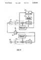
- FIG. 7is a block diagram of the control system for maintaining the proper phase relationship between the two harmonically related residences of the scanner assembly of either FIG. 3 or FIG. 6;
- FIG. 8is an alternate embodiment of the control system.
- the scanner assembly 38 of the confocal microscope 10 of FIG. 1resonantly provides substantially linear scanning in the x direction by employing an x-axis deflector assembly comprising two scanners 50 and 52 (FIG. 3) that oscillate, in a manner that will be described below, at harmonically related frequencies.
- scanner 50may be a 2-kHz resonant scanner
- scanner 52may be a 6-kHz resonant scanner.
- These frequency componentsare the two highest-amplitude frequency components of a 2-kHz triangular wave. If the phases and amplitudes of those two scanners' motions are properly related, therefore, they cause an x deflection that approximates triangular--i.e., substantially linear--motion of the target spot as a function of time.
- the y-axis motionis produced by a galvanometer scanner 58 arranged in a "paddle" configuration, i.e., so that the light beam hits mirror 60 at a point spaced from that mirror's pivot axis. Pivoting of mirror 60 changes not only the angle at which the incoming and outgoing beams 62 thus are deflected but also the point on the mirror 60 at which those beams hit it.
- the arrangementis such as to minimize the resultant motion of the points at which the beams hit x-axis mirrors 54 and 56--the beam appears to pivot about a "fulcrum" between mirrors 54 and 56--so that the sizes of those mirrors can be kept to a minimum, as is desirable for high-frequency resonant scanners.
- this placement of the resonant scanners 50 and 52 between the galvanometer scanner 58 and the (typically field-flattening) objective 12 (FIG. 1)yields an arrangement in which it is feasible to correct for the so-called pincushion distortion of the raster shape that otherwise would occur.
- zoomingis readily afforded by simply adjusting the amplitude of the scanner motion.
- panning--i.e., changing the position of the center of the image--is readily provided in the y-axis direction by appropriate control of the galvanometer scanner 58.
- Panning in the x directionis not as straightforward, however, because scanners 50 and 52 are resonant scanners and thus do not lend themselves to the addition of a "DC component" to their motion.
- a further scanner 64is included in the x-axis deflector assembly.
- This scanneris a galvanometer scanner and is used to superimpose a "DC" panning motion on the resonant motion that scanners 50 and 52 provide.
- Scanner 50is rotatably mounted so that galvanometer scanner 64 can pivot it by means of a motion reducer 66, which reduces the apparent moment of inertia of scanner 50 as seen by scanner 64.
- the motion reducerincludes an elastic band 68 shown in more detail in FIGS. 4A and 4B.
- the bandforms a slot 70 and a complementary neck region 72, and a tongue 74 is inserted through the slot 70 to form a loop 76, as FIG. 4B indicates.
- the shaft 78 of galvanometer scanner 64is inserted through the loop 76, and the band 68 is secured to the shaft 78, such as by staking through an opening 80.
- the ends of the band 68are then stretched along the surface of an arcuate fin 82 on the housing of resonant scanner 50 and secured at its ends. Because of the resilience of strip 68, the coupling provides negligible backlash.
- the resonant scanner 50 to which the galvanometer 64 is coupledis of the "reactionless" type exemplified by the scanners described in U.S. Pat. No. 4,919,500 to Paulsen.
- the resonant motion of a resonant scannerarises largely from the exchange of energy between the motion of a mass--primarily the mirror--and the deflection of a resilient member to which the mass is attached.
- the resilient memberis secured in some way to the scanner housing. The result is that a structure, such as the galvanometer scanner 64 of FIG. 3, to which the resonant-scanner housing is attached must bear not only the torque that results from the motor force but also the much greater torque that results from the force of the resilient member against the housing.
- a reactionless resonant scanneris arranged in a manner depicted in FIG. 5.
- the shaft 84 on which the mirror 54 is mountedis substantially supported only by housing pieces 86 and 88, which support it at the position of an enlarged mount region 90.
- the mirror 54is driven by a motor comprising windings 92 mounted on the housing and a magnetic pole piece 94 on the shaft 84.
- the shaft 84is made of resilient material, and the relationship of its torsional spring constant to the moment of inertia of the mirror 54 is such as to result in mirror motion that is approximately 180° out of phase with that of the pole piece (rotor) 94 when the scanner is driven at its intended, resonant frequency; that is, the torsional deformation of the shaft 84 results from the opposed motion of its opposite ends.
- the shaftis so arranged that the enlarged region 90 at which the housing supports it is a node of this resonant motion: the amplitude of the shaft's twisting motion is essentially zero at that point, increasing (in opposite directions) with distance from that point to maxima at the opposite ends of the shaft. In this way, the high torques involved in the resonant motion are not transmitted to the housing, and this greatly reduces the torque required of the galvanometer scanner 64.
- the x-axis deflectorincludes three mirrors 54, 56, and 100 rather than only two.
- a phase detector 104determines the phase difference between the (position or velocity) outputs of scanners 50 and 52. That is, the phase detector 104 generates an output proportional to the difference between the times of occurrence of a zero crossing of the fundamental component and of an adjacent zero crossing of the harmonic component.
- the resultant phase-difference outputis employed to control the phase (and, effectively, the frequency) of scanner 52.
- this phase differenceis instead employed by a heater circuit 106 to vary the current that flows through a heating element 107 (FIG. 5) that surrounds the scanner shaft 84.
- the spring constant of the shaft 84depends on its temperature, and the scanner's resonant frequency therefore does, too.
- the drive signal applied to the scanner driver 108 in the FIG. 7 arrangementdoes not come from a separate signal generator but instead is derived by positive feedback of scanner 52's output. Because of the positive feedback, the loop comprising the scanner 52 and its driver 108 exhibits a low-amplitude instability: that system self-oscillates, its amplitude continually increasing until driver 108's internal amplifiers reach saturation. To achieve the proper, predetermined amplitude set by the Fourier coefficient C 3 for the third harmonic, an amplitude-control circuit 110 adjusts an attenuator 112 so as to attenuate the saturated-amplifier output.
- scanner 50is simply arranged to self-oscillate by similar feedback to its driver 114, and an amplitude controller 116 employs a similar attenuator 118 to maintain the amplitude dictated by the Fourier coefficient C 1 for the fundamental component.
- An equivalent systemreplaces the heating element 107 with the coils of a magnetic spring that acts between the scanner's shaft and housing.
- a magnetic springmay be of the type described in U.S. Pat. No. 4,959,568 to Stokes, which I hereby incorporate by reference.
- Such systemstend not to provide as broad a resonant-frequency range as heating-element-type tunable scanners do, but their resonant frequencies can usually be changed more rapidly.
- FIG. 8depicts a control scheme that demonstrates the breadth of applicability of the tunable-scanner approach.
- a free-running oscillator 122provides the input to the driver 108 of scanner 52; that is, scanner 52 does not self-oscillate with its driver in this arrangement, and it accordingly does not automatically seek its system resonance, although the oscillator 122 will be arranged to drive scanner 52 as near to that resonance as is convenient.
- the scanner outputis applied, possibly after some phase adjustment in a phase shifter 124, to a frequency divider 126 whose output frequency is one-third its input frequency.
- the frequency divider 126applies its output to the driver 114 of scanner 50.
- the control system of FIG. 8maintains a constant phase relationship between the output of scanner 52 and the input to scanner 50.
- the relationship between the input and output of a high-Q scanner such as scanner 50 operating near resonancecan vary greatly, and this has been the source of problems in previous attempts to employ multiply resonant systems to provide desired non-sinusoidal periodic signals. Without more, therefore, the phase relationship between the outputs of scanner 50 and 52 would tend to vary even though the relationship between scanner 52's output and scanner 50's input is fixed. But the control system of FIG.
- FIG. 8employs a phase detector 128 similar to phase detector 104.
- Phase detector 128responds to the difference between the two scanner's outputs to provide a control signal to a heater controller 130 similar to controller 106 of FIG. 7, and this controller adjusts the resonant frequency of scanner 50.
- the FIG. 8 arrangementmaintains the proper phase relationship between the two harmonic components of the target-spot motion.
Landscapes
- Physics & Mathematics (AREA)
- General Physics & Mathematics (AREA)
- Optics & Photonics (AREA)
- Chemical & Material Sciences (AREA)
- Analytical Chemistry (AREA)
- Microscoopes, Condenser (AREA)
- Mechanical Optical Scanning Systems (AREA)
Abstract
Description
Claims (19)
Priority Applications (4)
| Application Number | Priority Date | Filing Date | Title |
|---|---|---|---|
| US07/911,192US5225923A (en) | 1992-07-09 | 1992-07-09 | Scanning microscope employing improved scanning mechanism |
| GB9311767AGB2268596A (en) | 1992-07-09 | 1993-06-08 | Scanning system for confocal microscope |
| DE4322694ADE4322694A1 (en) | 1992-07-09 | 1993-07-07 | Optical instrument with a scanner device |
| JP5169946AJPH06202023A (en) | 1992-07-09 | 1993-07-09 | Scanning microscope using improved scanning mechanism |
Applications Claiming Priority (1)
| Application Number | Priority Date | Filing Date | Title |
|---|---|---|---|
| US07/911,192US5225923A (en) | 1992-07-09 | 1992-07-09 | Scanning microscope employing improved scanning mechanism |
Publications (1)
| Publication Number | Publication Date |
|---|---|
| US5225923Atrue US5225923A (en) | 1993-07-06 |
Family
ID=25429884
Family Applications (1)
| Application Number | Title | Priority Date | Filing Date |
|---|---|---|---|
| US07/911,192Expired - Fee RelatedUS5225923A (en) | 1992-07-09 | 1992-07-09 | Scanning microscope employing improved scanning mechanism |
Country Status (4)
| Country | Link |
|---|---|
| US (1) | US5225923A (en) |
| JP (1) | JPH06202023A (en) |
| DE (1) | DE4322694A1 (en) |
| GB (1) | GB2268596A (en) |
Cited By (50)
| Publication number | Priority date | Publication date | Assignee | Title |
|---|---|---|---|---|
| EP0620468A1 (en)* | 1993-04-15 | 1994-10-19 | Kowa Co. Ltd. | Laser scanning optical microscope |
| US5452125A (en)* | 1990-07-28 | 1995-09-19 | Medical Research Council | Confocal imaging system for microscopy |
| WO1996037797A1 (en)* | 1995-05-26 | 1996-11-28 | General Scanning, Inc. | Wide field of view microscope and scanning system useful in the microscope |
| US5585632A (en)* | 1995-02-28 | 1996-12-17 | University Of Washington | Wide-angle infrared cloud imager |
| US5663825A (en)* | 1995-06-07 | 1997-09-02 | Martin Marietta Corporation | Stabilized step/stare scanning device |
| WO1997048001A1 (en)* | 1996-06-11 | 1997-12-18 | Evotec Biosystems Ag | Confocal microscope for optical determination of an observation volume |
| US5737121A (en)* | 1993-09-08 | 1998-04-07 | Dixon; Arthur E. | Real time scanning optical macroscope |
| US5760951A (en)* | 1992-09-01 | 1998-06-02 | Arthur Edward Dixon | Apparatus and method for scanning laser imaging of macroscopic samples |
| US5801881A (en)* | 1993-02-05 | 1998-09-01 | Carnegie Mellon University | Field synthesis and optical subsectioning for standing wave microscopy |
| US5811773A (en)* | 1988-05-11 | 1998-09-22 | Symbol Technologies, Inc. | Scanner with flexible flat cable electrically connected to light emitter |
| WO1998028640A3 (en)* | 1996-12-24 | 1998-10-08 | Leica Lasertechnik | Optical device for scanning a beam in two axes that are substantially perpendicular to each other |
| US5825013A (en)* | 1989-10-30 | 1998-10-20 | Symbol Technologies, Inc. | Electromagnetically activated scanner with suspended scanner component |
| EP0788617A4 (en)* | 1994-10-26 | 1999-01-27 | Univ Washington | MINIATURIZED OPTICAL SCANNER FOR TWO-AXIS SCANING SYSTEM |
| US5880465A (en)* | 1996-05-31 | 1999-03-09 | Kovex Corporation | Scanning confocal microscope with oscillating objective lens |
| US6094300A (en)* | 1996-11-21 | 2000-07-25 | Olympus Optical Co., Ltd. | Laser scanning microscope |
| US6140979A (en)* | 1998-08-05 | 2000-10-31 | Microvision, Inc. | Scanned display with pinch, timing, and distortion correction |
| US6160568A (en)* | 1997-05-27 | 2000-12-12 | Sdl, Inc. | Laser marking system and method of energy control |
| US6275250B1 (en) | 1998-05-26 | 2001-08-14 | Sdl, Inc. | Fiber gain medium marking system pumped or seeded by a modulated laser diode source and method of energy control |
| EP1113301A3 (en)* | 1999-11-24 | 2001-11-21 | Leica Microsystems Heidelberg GmbH | Apparatus for light beam deflection |
| US6362912B1 (en) | 1999-08-05 | 2002-03-26 | Microvision, Inc. | Scanned imaging apparatus with switched feeds |
| WO2002037164A1 (en)* | 2000-11-03 | 2002-05-10 | Microvision, Inc. | Frequency tunable resonant scanner and method of making |
| US6407856B1 (en) | 1997-06-11 | 2002-06-18 | Evotec Biosystems Ag | Confocal microscope for optical determination of an observation volume |
| US6433907B1 (en) | 1999-08-05 | 2002-08-13 | Microvision, Inc. | Scanned display with plurality of scanning assemblies |
| US6445362B1 (en) | 1999-08-05 | 2002-09-03 | Microvision, Inc. | Scanned display with variation compensation |
| US6515781B2 (en) | 1999-08-05 | 2003-02-04 | Microvision, Inc. | Scanned imaging apparatus with switched feeds |
| US6515278B2 (en) | 1999-08-05 | 2003-02-04 | Microvision, Inc. | Frequency tunable resonant scanner and method of making |
| US20030058190A1 (en)* | 2001-09-21 | 2003-03-27 | Microvision, Inc. | Scanned display with pinch, timing, and distortion correction |
| US20030063367A1 (en)* | 2001-09-11 | 2003-04-03 | Leica Microsystems Heidelberg Gmbh | Method for ascertaining position values, and scanning microscope |
| US6548796B1 (en) | 1999-06-23 | 2003-04-15 | Regents Of The University Of Minnesota | Confocal macroscope |
| US20030156323A1 (en)* | 2001-11-28 | 2003-08-21 | Overbeck James W. | Scanning microscopy, fluorescence detection, and laser beam positioning |
| USRE38307E1 (en) | 1995-02-03 | 2003-11-11 | The Regents Of The University Of California | Method and apparatus for three-dimensional microscopy with enhanced resolution |
| US20030214707A1 (en)* | 2002-05-18 | 2003-11-20 | Leica Microsystems Heidelberg Gmbh | Scanning microscope and beam deflection device |
| US6653621B2 (en) | 2001-03-23 | 2003-11-25 | Microvision, Inc. | Frequency tunable resonant scanner and method of making |
| US6661393B2 (en) | 1999-08-05 | 2003-12-09 | Microvision, Inc. | Scanned display with variation compensation |
| US6676266B2 (en) | 2000-12-08 | 2004-01-13 | Axon Instruments, Inc. | Optical pathway selector |
| US20040119004A1 (en)* | 2002-11-25 | 2004-06-24 | Microvision, Inc. | Frequency tunable resonant scanner and method of making |
| US6795221B1 (en) | 1999-08-05 | 2004-09-21 | Microvision, Inc. | Scanned display with switched feeds and distortion correction |
| US20050111089A1 (en)* | 1994-07-15 | 2005-05-26 | Baer Stephen C. | Superresolving microscopy apparatus |
| US20050237530A1 (en)* | 2004-04-26 | 2005-10-27 | Schnittker Mark V | Imaging apparatus for small spot optical characterization |
| US20050280818A1 (en)* | 2004-06-21 | 2005-12-22 | Olympus Corporation | Confocal observation system |
| US7098871B1 (en) | 1998-08-05 | 2006-08-29 | Microvision, Inc. | Optical scanning system with correction |
| WO2006124800A2 (en) | 2005-05-12 | 2006-11-23 | Lucid, Inc. | Confocal scanning microscope having optical and scanning systems which provide a handheld imaging head |
| US20080062161A1 (en)* | 1999-08-05 | 2008-03-13 | Microvision, Inc. | Apparatuses and methods for utilizing non-ideal light sources |
| US20090059363A1 (en)* | 2006-03-08 | 2009-03-05 | Carl Zeiss Surgical Gmbh | Microscope system |
| US20090141192A1 (en)* | 2007-12-03 | 2009-06-04 | Seiko Epson Corporation | Scanning image display system and scanning image display |
| WO2010069987A1 (en)* | 2008-12-19 | 2010-06-24 | Deutsches Krebsforschungszentrum | Method and device for dynamically shifting a light beam relative to an optic which focuses the light beam |
| CN102540670A (en)* | 2012-02-15 | 2012-07-04 | 凝辉(天津)科技有限责任公司 | Miniature single-catoptron and multi-light-source array type laser scanning projection device |
| EP3588944A3 (en)* | 2018-06-25 | 2020-02-26 | Faro Technologies, Inc. | Laser projector |
| US10884227B2 (en) | 2016-11-10 | 2021-01-05 | The Trustees Of Columbia University In The City Of New York | Rapid high-resolution imaging methods for large samples |
| CN112352185A (en)* | 2018-06-27 | 2021-02-09 | 微软技术许可有限责任公司 | Adjusting the resonant frequency of a scanning mirror |
Families Citing this family (9)
| Publication number | Priority date | Publication date | Assignee | Title |
|---|---|---|---|---|
| DE19710714C1 (en)* | 1997-03-14 | 1998-09-24 | Max Planck Gesellschaft | High speed periodic motion control of objects such as galvanometer mirror for deflecting laser scanning beam |
| JP4555905B2 (en)* | 1998-01-27 | 2010-10-06 | カール ツアイス マイクロイメージング ゲゼルシャフト ミット ベシュレンクテル ハフツング | Direction control system for scanner drive |
| DE19924709B4 (en)* | 1999-05-28 | 2005-01-20 | Leica Microsystems Heidelberg Gmbh | Device for fine positioning of a component |
| DE10209321A1 (en)* | 2002-03-02 | 2003-09-25 | Leica Microsystems | Device for deflecting a beam of light has a unit rotating on a first axis, fixed reflective surfaces and a beam of light picked up by the unit and passed on to a third reflective surface. |
| JP2004347663A (en)* | 2003-05-20 | 2004-12-09 | Fujitsu Ltd | Optical deflector |
| CN100387041C (en)* | 2005-09-16 | 2008-05-07 | 致伸科技股份有限公司 | Image scanner and image data compensation method |
| DE202010004547U1 (en) | 2010-04-01 | 2011-10-05 | Deutsches Krebsforschungszentrum Stiftung des öffentlichen Rechts | Electro-optical arrangement for ultra-fast scanning of an object |
| KR101483413B1 (en)* | 2013-07-24 | 2015-01-16 | 주식회사 휴비츠 | Silent resonant scanner |
| DE102015112151A1 (en) | 2015-07-24 | 2017-02-09 | Lpkf Laser & Electronics Ag | Method and device for laser processing of a substrate with multiple deflection of a laser radiation |
Citations (14)
| Publication number | Priority date | Publication date | Assignee | Title |
|---|---|---|---|---|
| US3619028A (en)* | 1970-06-25 | 1971-11-09 | Honeywell Inc | Fourier optical scanner |
| US4314154A (en)* | 1979-01-17 | 1982-02-02 | Canon Kabushiki Kaisha | Two-dimensional scanning device having compensation for scanned image strain |
| US4370019A (en)* | 1978-12-23 | 1983-01-25 | Canon Kabushiki Kaisha | Optical scanning device with temperature control means |
| US4631581A (en)* | 1984-03-15 | 1986-12-23 | Sarastro Ab | Method and apparatus for microphotometering microscope specimens |
| US4788423A (en)* | 1987-05-26 | 1988-11-29 | Santa Barbara Research Center | Two-mirror scanning system |
| US4859846A (en)* | 1988-07-21 | 1989-08-22 | Burrer Gordon J | Dual-mode resonant scanning system |
| US4874215A (en)* | 1987-04-23 | 1989-10-17 | General Scanning, Inc. | Tunable resonant mechanical system |
| US4919500A (en)* | 1988-09-09 | 1990-04-24 | General Scanning, Inc. | Torsion bar scanner with damping |
| US4959568A (en)* | 1986-08-05 | 1990-09-25 | General Scanning, Inc. | Dynamically tunable resonant device with electric control |
| US4975626A (en)* | 1988-05-27 | 1990-12-04 | Tokyo Electric Company, Ltd. | Scanner motor controller for controlling the rotating speed of a scanner motor |
| US5032720A (en)* | 1988-04-21 | 1991-07-16 | White John G | Confocal imaging system |
| US5048904A (en)* | 1990-07-06 | 1991-09-17 | General Scanning, Inc. | Two-mirror scanner with pincushion error correction |
| US5130838A (en)* | 1990-06-18 | 1992-07-14 | Pioneer Electronic Corporation | Laser projection type display unit |
| US5144477A (en)* | 1988-04-11 | 1992-09-01 | Medical Research Council | Method of operating a scanning confocal imaging system |
Family Cites Families (1)
| Publication number | Priority date | Publication date | Assignee | Title |
|---|---|---|---|---|
| US5047630A (en)* | 1990-08-22 | 1991-09-10 | Confer Charles L | Modified dual-mode resonant scanning system |
- 1992
- 1992-07-09USUS07/911,192patent/US5225923A/ennot_activeExpired - Fee Related
- 1993
- 1993-06-08GBGB9311767Apatent/GB2268596A/ennot_activeWithdrawn
- 1993-07-07DEDE4322694Apatent/DE4322694A1/ennot_activeWithdrawn
- 1993-07-09JPJP5169946Apatent/JPH06202023A/enactivePending
Patent Citations (14)
| Publication number | Priority date | Publication date | Assignee | Title |
|---|---|---|---|---|
| US3619028A (en)* | 1970-06-25 | 1971-11-09 | Honeywell Inc | Fourier optical scanner |
| US4370019A (en)* | 1978-12-23 | 1983-01-25 | Canon Kabushiki Kaisha | Optical scanning device with temperature control means |
| US4314154A (en)* | 1979-01-17 | 1982-02-02 | Canon Kabushiki Kaisha | Two-dimensional scanning device having compensation for scanned image strain |
| US4631581A (en)* | 1984-03-15 | 1986-12-23 | Sarastro Ab | Method and apparatus for microphotometering microscope specimens |
| US4959568A (en)* | 1986-08-05 | 1990-09-25 | General Scanning, Inc. | Dynamically tunable resonant device with electric control |
| US4874215A (en)* | 1987-04-23 | 1989-10-17 | General Scanning, Inc. | Tunable resonant mechanical system |
| US4788423A (en)* | 1987-05-26 | 1988-11-29 | Santa Barbara Research Center | Two-mirror scanning system |
| US5144477A (en)* | 1988-04-11 | 1992-09-01 | Medical Research Council | Method of operating a scanning confocal imaging system |
| US5032720A (en)* | 1988-04-21 | 1991-07-16 | White John G | Confocal imaging system |
| US4975626A (en)* | 1988-05-27 | 1990-12-04 | Tokyo Electric Company, Ltd. | Scanner motor controller for controlling the rotating speed of a scanner motor |
| US4859846A (en)* | 1988-07-21 | 1989-08-22 | Burrer Gordon J | Dual-mode resonant scanning system |
| US4919500A (en)* | 1988-09-09 | 1990-04-24 | General Scanning, Inc. | Torsion bar scanner with damping |
| US5130838A (en)* | 1990-06-18 | 1992-07-14 | Pioneer Electronic Corporation | Laser projection type display unit |
| US5048904A (en)* | 1990-07-06 | 1991-09-17 | General Scanning, Inc. | Two-mirror scanner with pincushion error correction |
Non-Patent Citations (2)
| Title |
|---|
| Montagu, Jean I., "Tunable Resonant Scanners", Proceedings of SPIE--The International Society for Optical Engineering, vol. 817, Aug. 20-21, 1987. |
| Montagu, Jean I., Tunable Resonant Scanners , Proceedings of SPIE The International Society for Optical Engineering, vol. 817, Aug. 20 21, 1987.* |
Cited By (88)
| Publication number | Priority date | Publication date | Assignee | Title |
|---|---|---|---|---|
| US5811773A (en)* | 1988-05-11 | 1998-09-22 | Symbol Technologies, Inc. | Scanner with flexible flat cable electrically connected to light emitter |
| US5825013A (en)* | 1989-10-30 | 1998-10-20 | Symbol Technologies, Inc. | Electromagnetically activated scanner with suspended scanner component |
| US5452125A (en)* | 1990-07-28 | 1995-09-19 | Medical Research Council | Confocal imaging system for microscopy |
| US6072624A (en)* | 1992-01-09 | 2000-06-06 | Biomedical Photometrics Inc. | Apparatus and method for scanning laser imaging of macroscopic samples |
| US5760951A (en)* | 1992-09-01 | 1998-06-02 | Arthur Edward Dixon | Apparatus and method for scanning laser imaging of macroscopic samples |
| US5801881A (en)* | 1993-02-05 | 1998-09-01 | Carnegie Mellon University | Field synthesis and optical subsectioning for standing wave microscopy |
| US6055097A (en)* | 1993-02-05 | 2000-04-25 | Carnegie Mellon University | Field synthesis and optical subsectioning for standing wave microscopy |
| US5691839A (en)* | 1993-04-15 | 1997-11-25 | Kowa Company Ltd. | Laser scanning optical microscope |
| EP0620468A1 (en)* | 1993-04-15 | 1994-10-19 | Kowa Co. Ltd. | Laser scanning optical microscope |
| US5737121A (en)* | 1993-09-08 | 1998-04-07 | Dixon; Arthur E. | Real time scanning optical macroscope |
| US20050111089A1 (en)* | 1994-07-15 | 2005-05-26 | Baer Stephen C. | Superresolving microscopy apparatus |
| EP0788617A4 (en)* | 1994-10-26 | 1999-01-27 | Univ Washington | MINIATURIZED OPTICAL SCANNER FOR TWO-AXIS SCANING SYSTEM |
| EP1168032A3 (en)* | 1994-10-26 | 2004-03-03 | Board Of Regents Of The University Of Washington | Miniature optical scanner for a two axis scanning system |
| USRE38307E1 (en) | 1995-02-03 | 2003-11-11 | The Regents Of The University Of California | Method and apparatus for three-dimensional microscopy with enhanced resolution |
| US5585632A (en)* | 1995-02-28 | 1996-12-17 | University Of Washington | Wide-angle infrared cloud imager |
| WO1996037797A1 (en)* | 1995-05-26 | 1996-11-28 | General Scanning, Inc. | Wide field of view microscope and scanning system useful in the microscope |
| US5663825A (en)* | 1995-06-07 | 1997-09-02 | Martin Marietta Corporation | Stabilized step/stare scanning device |
| US5880465A (en)* | 1996-05-31 | 1999-03-09 | Kovex Corporation | Scanning confocal microscope with oscillating objective lens |
| US6122098A (en)* | 1996-06-11 | 2000-09-19 | Evotec Biosystems A.G. | Confocal microscope for optical determination of an observation volume |
| WO1997048001A1 (en)* | 1996-06-11 | 1997-12-18 | Evotec Biosystems Ag | Confocal microscope for optical determination of an observation volume |
| US6094300A (en)* | 1996-11-21 | 2000-07-25 | Olympus Optical Co., Ltd. | Laser scanning microscope |
| US6211988B1 (en) | 1996-12-24 | 2001-04-03 | Leica Microsystems Heidelberg Gmbh | Optical device for scanning a beam in two axes that are substantially perpendicular to each other |
| WO1998028640A3 (en)* | 1996-12-24 | 1998-10-08 | Leica Lasertechnik | Optical device for scanning a beam in two axes that are substantially perpendicular to each other |
| US6160568A (en)* | 1997-05-27 | 2000-12-12 | Sdl, Inc. | Laser marking system and method of energy control |
| US6489985B1 (en) | 1997-05-27 | 2002-12-03 | Jds Uniphase Corporation | Laser marking system and method of energy control |
| US6407856B1 (en) | 1997-06-11 | 2002-06-18 | Evotec Biosystems Ag | Confocal microscope for optical determination of an observation volume |
| US6275250B1 (en) | 1998-05-26 | 2001-08-14 | Sdl, Inc. | Fiber gain medium marking system pumped or seeded by a modulated laser diode source and method of energy control |
| US20080136742A1 (en)* | 1998-08-05 | 2008-06-12 | Microvision, Inc. | Method and Apparatus for Compensating for Distortion in a Scanned Beam System |
| US20060284790A1 (en)* | 1998-08-05 | 2006-12-21 | Tegreene Clarence T | Optical scanning system with correction |
| US7098871B1 (en) | 1998-08-05 | 2006-08-29 | Microvision, Inc. | Optical scanning system with correction |
| US7428093B2 (en) | 1998-08-05 | 2008-09-23 | Microvision, Inc. | Optical scanning system with correction |
| US6140979A (en)* | 1998-08-05 | 2000-10-31 | Microvision, Inc. | Scanned display with pinch, timing, and distortion correction |
| US6548796B1 (en) | 1999-06-23 | 2003-04-15 | Regents Of The University Of Minnesota | Confocal macroscope |
| US20030151742A1 (en)* | 1999-06-23 | 2003-08-14 | Regents Of The University Of Minnesota | Confocal macroscope |
| US20080062161A1 (en)* | 1999-08-05 | 2008-03-13 | Microvision, Inc. | Apparatuses and methods for utilizing non-ideal light sources |
| USRE41375E1 (en)* | 1999-08-05 | 2010-06-15 | Microvision, Inc. | Resonant beam scanner with raster pinch compensation |
| USRE41374E1 (en)* | 1999-08-05 | 2010-06-15 | Microvision, Inc. | Frequency tunable resonant scanner and method of making |
| US7473888B2 (en) | 1999-08-05 | 2009-01-06 | Microvision, Inc. | Display with compensated light source drive |
| US6362912B1 (en) | 1999-08-05 | 2002-03-26 | Microvision, Inc. | Scanned imaging apparatus with switched feeds |
| US7209271B2 (en) | 1999-08-05 | 2007-04-24 | Microvision, Inc | Multiple beam scanning imager |
| US6661393B2 (en) | 1999-08-05 | 2003-12-09 | Microvision, Inc. | Scanned display with variation compensation |
| US20070063134A1 (en)* | 1999-08-05 | 2007-03-22 | Wine David W | Display with compensated light source drive |
| US6515278B2 (en) | 1999-08-05 | 2003-02-04 | Microvision, Inc. | Frequency tunable resonant scanner and method of making |
| US6433907B1 (en) | 1999-08-05 | 2002-08-13 | Microvision, Inc. | Scanned display with plurality of scanning assemblies |
| US6445362B1 (en) | 1999-08-05 | 2002-09-03 | Microvision, Inc. | Scanned display with variation compensation |
| US7075687B2 (en) | 1999-08-05 | 2006-07-11 | Microvision, Inc. | Scanned beam image capture device with a plurality of scan regions |
| US6762867B2 (en) | 1999-08-05 | 2004-07-13 | Microvision, Inc. | Scanned display with plurality of scanning assemblies |
| US20040179254A1 (en)* | 1999-08-05 | 2004-09-16 | Microvision, Inc. | Scanned imaging apparatus with switched feeds |
| US6795221B1 (en) | 1999-08-05 | 2004-09-21 | Microvision, Inc. | Scanned display with switched feeds and distortion correction |
| US20040223202A1 (en)* | 1999-08-05 | 2004-11-11 | Microvision, Inc. | Scanned beam image capture device with a plurality of scan regions |
| US6515781B2 (en) | 1999-08-05 | 2003-02-04 | Microvision, Inc. | Scanned imaging apparatus with switched feeds |
| US7002717B1 (en) | 1999-11-24 | 2006-02-21 | Leica Microsystems Cms Gmbh | Apparatus for beam deflection |
| EP1113301A3 (en)* | 1999-11-24 | 2001-11-21 | Leica Microsystems Heidelberg GmbH | Apparatus for light beam deflection |
| EP1734395A1 (en)* | 2000-11-03 | 2006-12-20 | Microvision, Inc. | Frequency tunable resonant scanner and method of making |
| WO2002037164A1 (en)* | 2000-11-03 | 2002-05-10 | Microvision, Inc. | Frequency tunable resonant scanner and method of making |
| US6676266B2 (en) | 2000-12-08 | 2004-01-13 | Axon Instruments, Inc. | Optical pathway selector |
| US6653621B2 (en) | 2001-03-23 | 2003-11-25 | Microvision, Inc. | Frequency tunable resonant scanner and method of making |
| US6714331B2 (en) | 2001-04-20 | 2004-03-30 | Microvision, Inc. | Scanned imaging apparatus with switched feeds |
| US6859294B2 (en) | 2001-09-11 | 2005-02-22 | Leica Microsystems Heidelberg Gmbh | Method for ascertaining position values, and scanning microscope |
| US20030063367A1 (en)* | 2001-09-11 | 2003-04-03 | Leica Microsystems Heidelberg Gmbh | Method for ascertaining position values, and scanning microscope |
| US20030058190A1 (en)* | 2001-09-21 | 2003-03-27 | Microvision, Inc. | Scanned display with pinch, timing, and distortion correction |
| US7023402B2 (en) | 2001-09-21 | 2006-04-04 | Microvision, Inc. | Scanned display with pinch, timing, and distortion correction |
| US7050208B2 (en) | 2001-11-28 | 2006-05-23 | Overbeck James W | Scanning microscopy, fluorescence detection, and laser beam positioning |
| US20030156323A1 (en)* | 2001-11-28 | 2003-08-21 | Overbeck James W. | Scanning microscopy, fluorescence detection, and laser beam positioning |
| US20030214707A1 (en)* | 2002-05-18 | 2003-11-20 | Leica Microsystems Heidelberg Gmbh | Scanning microscope and beam deflection device |
| US20040075624A1 (en)* | 2002-08-09 | 2004-04-22 | Microvision, Inc. | Image capture device with projected display |
| US7071931B2 (en) | 2002-08-09 | 2006-07-04 | Microvision, Inc. | Image capture device with projected display |
| US20040119004A1 (en)* | 2002-11-25 | 2004-06-24 | Microvision, Inc. | Frequency tunable resonant scanner and method of making |
| US6924476B2 (en) | 2002-11-25 | 2005-08-02 | Microvision, Inc. | Resonant beam scanner with raster pinch compensation |
| US20050237530A1 (en)* | 2004-04-26 | 2005-10-27 | Schnittker Mark V | Imaging apparatus for small spot optical characterization |
| US7355702B2 (en)* | 2004-06-21 | 2008-04-08 | Olympus Corporation | Confocal observation system |
| US20050280818A1 (en)* | 2004-06-21 | 2005-12-22 | Olympus Corporation | Confocal observation system |
| US9055867B2 (en) | 2005-05-12 | 2015-06-16 | Caliber Imaging & Diagnostics, Inc. | Confocal scanning microscope having optical and scanning systems which provide a handheld imaging head |
| WO2006124800A2 (en) | 2005-05-12 | 2006-11-23 | Lucid, Inc. | Confocal scanning microscope having optical and scanning systems which provide a handheld imaging head |
| US20090097108A1 (en)* | 2005-05-12 | 2009-04-16 | Fox William J | Confocal scanning microscope having optical and scanning systems which provide a handheld imaging head |
| US12053261B2 (en) | 2005-05-12 | 2024-08-06 | Caliber Imaging & Diagnostics, Inc. | Handheld confocal scanning optical microscope systems having oscillating mirrors with varying scan angle to zoom |
| US10555674B2 (en) | 2005-05-12 | 2020-02-11 | Caliber Imaging & Diagnostics, Inc. | Confocal scanning microscope having optical and scanning systems which provide a handheld imaging head |
| US20090059363A1 (en)* | 2006-03-08 | 2009-03-05 | Carl Zeiss Surgical Gmbh | Microscope system |
| US8098414B2 (en)* | 2007-12-03 | 2012-01-17 | Seiko Epson Corporation | Scanning image display system and scanning image display |
| US20090141192A1 (en)* | 2007-12-03 | 2009-06-04 | Seiko Epson Corporation | Scanning image display system and scanning image display |
| US8520280B2 (en) | 2008-12-19 | 2013-08-27 | Deutsches Krebsforschungszentrum | Method and apparatus for dynamically shifting a light beam with regard to an optic focussing the light beam |
| WO2010069987A1 (en)* | 2008-12-19 | 2010-06-24 | Deutsches Krebsforschungszentrum | Method and device for dynamically shifting a light beam relative to an optic which focuses the light beam |
| CN102540670A (en)* | 2012-02-15 | 2012-07-04 | 凝辉(天津)科技有限责任公司 | Miniature single-catoptron and multi-light-source array type laser scanning projection device |
| US10884227B2 (en) | 2016-11-10 | 2021-01-05 | The Trustees Of Columbia University In The City Of New York | Rapid high-resolution imaging methods for large samples |
| US11506877B2 (en) | 2016-11-10 | 2022-11-22 | The Trustees Of Columbia University In The City Of New York | Imaging instrument having objective axis and light sheet or light beam projector axis intersecting at less than 90 degrees |
| EP3588944A3 (en)* | 2018-06-25 | 2020-02-26 | Faro Technologies, Inc. | Laser projector |
| US10884257B2 (en) | 2018-06-25 | 2021-01-05 | Faro Technologies, Inc. | Background light suppression for a laser projector |
| CN112352185A (en)* | 2018-06-27 | 2021-02-09 | 微软技术许可有限责任公司 | Adjusting the resonant frequency of a scanning mirror |
Also Published As
| Publication number | Publication date |
|---|---|
| DE4322694A1 (en) | 1994-01-13 |
| GB9311767D0 (en) | 1993-07-28 |
| JPH06202023A (en) | 1994-07-22 |
| GB2268596A (en) | 1994-01-12 |
Similar Documents
| Publication | Publication Date | Title |
|---|---|---|
| US5225923A (en) | Scanning microscope employing improved scanning mechanism | |
| US5048904A (en) | Two-mirror scanner with pincushion error correction | |
| US5936764A (en) | Laser scanning optical microscope | |
| US6157352A (en) | Virtual retinal display with expanded exit pupil | |
| KR0181724B1 (en) | Fiber optic ribbon subminiature display for head/helmet mounted display | |
| US5663825A (en) | Stabilized step/stare scanning device | |
| US5835252A (en) | Device for generating annular pictures | |
| CN102652275A (en) | Scanning device, image display device, and method for controlling image display device | |
| CN116107076B (en) | Single-objective light sheet three-dimensional fluorescence imaging system | |
| KR19980071039A (en) | Optical microscope device | |
| WO2012168980A1 (en) | Image display device | |
| US20020176017A1 (en) | Scanning type image pick-up apparatus and a scanning type laser beam receive apparatus | |
| US7154652B2 (en) | Light scanning optical system, image projection apparatus, and image display system | |
| US5150249A (en) | Two-mirror scanner with pincushion error correction | |
| US4902893A (en) | Passive infrared radiation scanning system | |
| US4264119A (en) | Scanning optical system | |
| JP2000171742A (en) | Scanning optical system and scanning imaging optical system | |
| US4674826A (en) | Optico-mechanical scanning device | |
| US6169621B1 (en) | Device for the production of an image on a screen by illuminating picture elements in a plurality of partial images | |
| KR20010041123A (en) | Device for the projection of a video image | |
| JPH10260359A (en) | Image rotating device | |
| US6097526A (en) | Scanning type image viewing optical system | |
| JPS61295526A (en) | Photoscanner | |
| US4004087A (en) | Panning pyroelectric vidicon system | |
| Loney | Scanner component and head development for confocal microscopy using moving mirror technology |
Legal Events
| Date | Code | Title | Description |
|---|---|---|---|
| AS | Assignment | Owner name:GENERAL SCANNING, INC., MASSACHUSETTS Free format text:ASSIGNMENT OF ASSIGNORS INTEREST.;ASSIGNOR:MONTAGU, JEAN I.;REEL/FRAME:006186/0933 Effective date:19920707 | |
| FEPP | Fee payment procedure | Free format text:PAYOR NUMBER ASSIGNED (ORIGINAL EVENT CODE: ASPN); ENTITY STATUS OF PATENT OWNER: LARGE ENTITY | |
| REMI | Maintenance fee reminder mailed | ||
| FPAY | Fee payment | Year of fee payment:4 | |
| SULP | Surcharge for late payment | ||
| FPAY | Fee payment | Year of fee payment:8 | |
| SULP | Surcharge for late payment | Year of fee payment:7 | |
| AS | Assignment | Owner name:GSI LUMONICS CORPORATION, MICHIGAN Free format text:ASSIGNMENT OF ASSIGNORS INTEREST;ASSIGNOR:GENERAL SCANNING, INC.;REEL/FRAME:013751/0518 Effective date:20030623 | |
| REMI | Maintenance fee reminder mailed | ||
| REMI | Maintenance fee reminder mailed | ||
| LAPS | Lapse for failure to pay maintenance fees | ||
| STCH | Information on status: patent discontinuation | Free format text:PATENT EXPIRED DUE TO NONPAYMENT OF MAINTENANCE FEES UNDER 37 CFR 1.362 | |
| FP | Lapsed due to failure to pay maintenance fee | Effective date:20050706 | |
| AS | Assignment | Owner name:THE BANK OF NEW YORK MELLON TRUST COMPANY, N.A., A Free format text:SECURITY AGREEMENT;ASSIGNORS:GSI GROUP INC.;GSI GROUP CORPORATION;MES INTERNATIONAL INC.;AND OTHERS;REEL/FRAME:024755/0537 Effective date:20100723 | |
| AS | Assignment | Owner name:EXCEL TECHNOLOGY INC., MASSACHUSETTS Free format text:RELEASE;ASSIGNOR:THE BANK OF NEW YORK MELLON TRUST COMPANY, N.A.;REEL/FRAME:027127/0368 Effective date:20111019 Owner name:MICROE SYSTEMS CORP., MASSACHUSETTS Free format text:RELEASE;ASSIGNOR:THE BANK OF NEW YORK MELLON TRUST COMPANY, N.A.;REEL/FRAME:027127/0368 Effective date:20111019 Owner name:GSI GROUP INC., MASSACHUSETTS Free format text:RELEASE;ASSIGNOR:THE BANK OF NEW YORK MELLON TRUST COMPANY, N.A.;REEL/FRAME:027127/0368 Effective date:20111019 Owner name:CAMBRIDGE TECHNOLOGY INC., MASSACHUSETTS Free format text:RELEASE;ASSIGNOR:THE BANK OF NEW YORK MELLON TRUST COMPANY, N.A.;REEL/FRAME:027127/0368 Effective date:20111019 Owner name:CONTINUUM ELECTRO-OPTICS INC., MASSACHUSETTS Free format text:RELEASE;ASSIGNOR:THE BANK OF NEW YORK MELLON TRUST COMPANY, N.A.;REEL/FRAME:027127/0368 Effective date:20111019 Owner name:GSI GROUP CORPORATION, MASSACHUSETTS Free format text:RELEASE;ASSIGNOR:THE BANK OF NEW YORK MELLON TRUST COMPANY, N.A.;REEL/FRAME:027127/0368 Effective date:20111019 Owner name:CONTROL LASER CORPORATION (D/B/A BAUBLYS CONTROL L Free format text:RELEASE;ASSIGNOR:THE BANK OF NEW YORK MELLON TRUST COMPANY, N.A.;REEL/FRAME:027127/0368 Effective date:20111019 Owner name:MES INTERNATIONAL INC., MASSACHUSETTS Free format text:RELEASE;ASSIGNOR:THE BANK OF NEW YORK MELLON TRUST COMPANY, N.A.;REEL/FRAME:027127/0368 Effective date:20111019 Owner name:SYNRAD INC., MASSACHUSETTS Free format text:RELEASE;ASSIGNOR:THE BANK OF NEW YORK MELLON TRUST COMPANY, N.A.;REEL/FRAME:027127/0368 Effective date:20111019 Owner name:THE OPTICAL CORPORATION, MASSACHUSETTS Free format text:RELEASE;ASSIGNOR:THE BANK OF NEW YORK MELLON TRUST COMPANY, N.A.;REEL/FRAME:027127/0368 Effective date:20111019 Owner name:QUANTRONIX CORPORATION, MASSACHUSETTS Free format text:RELEASE;ASSIGNOR:THE BANK OF NEW YORK MELLON TRUST COMPANY, N.A.;REEL/FRAME:027127/0368 Effective date:20111019 Owner name:PHOTO RESEARCH INC., MASSACHUSETTS Free format text:RELEASE;ASSIGNOR:THE BANK OF NEW YORK MELLON TRUST COMPANY, N.A.;REEL/FRAME:027127/0368 Effective date:20111019 |