US5223760A - Wheel speed sensor for drive axle - Google Patents
Wheel speed sensor for drive axleDownload PDFInfo
- Publication number
- US5223760A US5223760AUS07/785,243US78524391AUS5223760AUS 5223760 AUS5223760 AUS 5223760AUS 78524391 AUS78524391 AUS 78524391AUS 5223760 AUS5223760 AUS 5223760A
- Authority
- US
- United States
- Prior art keywords
- speed sensor
- rotor
- differential case
- stator
- rotational speed
- Prior art date
- Legal status (The legal status is an assumption and is not a legal conclusion. Google has not performed a legal analysis and makes no representation as to the accuracy of the status listed.)
- Expired - Fee Related
Links
- 230000004907fluxEffects0.000claimsdescription11
- 239000000356contaminantSubstances0.000claimsdescription4
- 230000000717retained effectEffects0.000claims4
- 230000009977dual effectEffects0.000abstractdescription4
- 238000012986modificationMethods0.000description6
- 230000004048modificationEffects0.000description6
- 230000007423decreaseEffects0.000description4
- 239000000463materialSubstances0.000description4
- 238000013461designMethods0.000description3
- 238000000034methodMethods0.000description3
- 239000000853adhesiveSubstances0.000description2
- 230000001070adhesive effectEffects0.000description2
- 238000010276constructionMethods0.000description2
- 238000009434installationMethods0.000description2
- 238000005259measurementMethods0.000description2
- 229910000831SteelInorganic materials0.000description1
- 230000006978adaptationEffects0.000description1
- 230000003044adaptive effectEffects0.000description1
- 230000000712assemblyEffects0.000description1
- 238000000429assemblyMethods0.000description1
- 230000006835compressionEffects0.000description1
- 238000007906compressionMethods0.000description1
- 238000005530etchingMethods0.000description1
- 238000010348incorporationMethods0.000description1
- 238000002955isolationMethods0.000description1
- 239000010687lubricating oilSubstances0.000description1
- 239000000696magnetic materialSubstances0.000description1
- 238000012423maintenanceMethods0.000description1
- 239000002991molded plasticSubstances0.000description1
- 239000004033plasticSubstances0.000description1
- 238000012545processingMethods0.000description1
- 238000007789sealingMethods0.000description1
- 239000010959steelSubstances0.000description1
- 239000000725suspensionSubstances0.000description1
- 238000004804windingMethods0.000description1
Images


Classifications
- G—PHYSICS
- G01—MEASURING; TESTING
- G01P—MEASURING LINEAR OR ANGULAR SPEED, ACCELERATION, DECELERATION, OR SHOCK; INDICATING PRESENCE, ABSENCE, OR DIRECTION, OF MOVEMENT
- G01P3/00—Measuring linear or angular speed; Measuring differences of linear or angular speeds
- G01P3/42—Devices characterised by the use of electric or magnetic means
- G01P3/44—Devices characterised by the use of electric or magnetic means for measuring angular speed
- G01P3/48—Devices characterised by the use of electric or magnetic means for measuring angular speed by measuring frequency of generated current or voltage
- G01P3/481—Devices characterised by the use of electric or magnetic means for measuring angular speed by measuring frequency of generated current or voltage of pulse signals
- G01P3/487—Devices characterised by the use of electric or magnetic means for measuring angular speed by measuring frequency of generated current or voltage of pulse signals delivered by rotating magnets
- G—PHYSICS
- G01—MEASURING; TESTING
- G01P—MEASURING LINEAR OR ANGULAR SPEED, ACCELERATION, DECELERATION, OR SHOCK; INDICATING PRESENCE, ABSENCE, OR DIRECTION, OF MOVEMENT
- G01P3/00—Measuring linear or angular speed; Measuring differences of linear or angular speeds
- G01P3/42—Devices characterised by the use of electric or magnetic means
- G01P3/44—Devices characterised by the use of electric or magnetic means for measuring angular speed
- G01P3/443—Devices characterised by the use of electric or magnetic means for measuring angular speed mounted in bearings
- G—PHYSICS
- G01—MEASURING; TESTING
- G01P—MEASURING LINEAR OR ANGULAR SPEED, ACCELERATION, DECELERATION, OR SHOCK; INDICATING PRESENCE, ABSENCE, OR DIRECTION, OF MOVEMENT
- G01P3/00—Measuring linear or angular speed; Measuring differences of linear or angular speeds
- G01P3/42—Devices characterised by the use of electric or magnetic means
- G01P3/44—Devices characterised by the use of electric or magnetic means for measuring angular speed
- G01P3/48—Devices characterised by the use of electric or magnetic means for measuring angular speed by measuring frequency of generated current or voltage
- G01P3/481—Devices characterised by the use of electric or magnetic means for measuring angular speed by measuring frequency of generated current or voltage of pulse signals
- G01P3/488—Devices characterised by the use of electric or magnetic means for measuring angular speed by measuring frequency of generated current or voltage of pulse signals delivered by variable reluctance detectors
Definitions
- This inventionrelates to a wheel speed sensor for a drive axle and, more specifically a wheel speed sensor for incorporation in an axle requiring minimal modification thereof.
- An automotive traction control or adaptive braking systemrequires intelligence of the speed of the wheels of the vehicle.
- Existing systemsuse sensors which require extensive modification to existing drive axles.
- An exampleis U.S. Pat. No. 3,769,533 which incorporates circumferentially spaced gear teeth formed n the external surface of the differential case and the axle shaft. These teeth interact with an electromagnetic pickup which is carried in an aperture formed in the axle housing. Extensive modification of the axle housing is required to adapt the magnetic pick-up.
- any magnetizable contaminants which may be present in the lubricating oil of the axleare drawn to the magnetic pickup producing a continuous buildup which ultimately results in a magnetic shunt causing system failure.
- electromagnetic pickupsare located proximate one another so as to gather wheel speed data in the manner described in U.S. Pat. No. 3,769,533, magnetic interference between pickups results in erroneous signals regarding wheel speeds.
- the present wheel speed sensorimproves upon prior art speed sensors by utilizing an axially compact design to permit efficient adaptation to existing axles while requiring a minimum of modification.
- the present speed sensorincludes a rotor and a stator, each having teeth defining slots, in conjunction with an annular magnet to increase and decrease magnetic flux in the magnetic circuit.
- Such a structurepermits measurement of rotational speed in accordance with the increase and decrease of magnetic flux.
- the changes in flux generated by the rotor systeminduces an alternating voltage in a coil of wire in a well known manner to produce signals representative of rotational speed.
- a single speed signal corresponding to the average speed of both axle shaftsis produced by a single sensor which determines the speed of the differential case.
- dual signals which may be used to determine the actual speed of each axle shaftare produced by dual sensors each providing a signal which corresponds with one axle shaft speed and the speed of the differential case.
- FIG. 1is a perspective view of a typical rotary sensor which may be used with the present invention
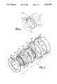
- FIG. 2is an exploded view of the sensor shown in FIG. 1;
- FIG. 3is a sectional view taken along III--III of the sensor shown in FIG. 1;
- FIG. 4is a view of the sensor shown in FIG. 3 mounted in a differential case adjusting ring to measure differential case speed;
- FIG. 5is a view of dual sensors mounted in a differential housing driven by the differential case and an axle shaft.
- FIG. 6is a side elevation view of the bearing adjusting ring having castellations
- FIG. 7is an end view of the adjusting ring taken along line 7--7 of FIG. 6;
- the preferred embodiment of the present inventionincludes an annular rotational speed sensor incorporated into an axle housing.
- An example of a suitable sensoris indicated generally at 10 in FIG. 1.
- the sensoris mounted in stationary bore 12, and is driven by rotating shaft 14. Electrical leads 16 come from an internal sensing coil.
- the details of construction of any one of the embodiments of a rotational speed sensor which may be used in the present inventionare described in now abandoned application Ser. No. 07/236,689, filed Aug. 24, 1988 and continuations following therefrom.
- FIG. 2the components of the sensor telescope into sensor retainer 18 from the left edge thereof. Edge 20 is rolled over to cooperate with lip 22 in retaining the sensor components within retainer 8.
- the double-lipped design shown in FIG. 2is merely one example of suitable retaining means that may be used on sensors incorporated in the present invention. A variety of other retaining means may be used, including adhesives.
- Annular stator elements 24 and 26provide a closed magnetic path for magnetic flux extending from inner edge 28 to outer edge 30.
- Circumferentially spaced, radially disposed teeth 32 and slots 31are formed on the inner faces of stator elements 24 and 26, and act in conjunction with corresponding teeth 34 and slots 33 formed in rotor 36 to provide the means for sensing rotational speed.
- Axially poled annular magnet 38provides magnetic flux for sensor 10.
- a sensing coilshown encapsulated at 40, consists of a simple multi-turn winding having an axis coincident with the axis of the assembled sensor. Lead wires 16 extend from the two ends of coil 40 to connect the alternating voltage representing rotational speed signals to an external signal processing unit (not shown).
- rotor 36is driven by shaft 14.
- Rotor 36nests within coil 40, and the rotor-coil combination nests coaxially within magnet 38. This assembly in turn is located coaxially with and between stator elements 24 and 26.
- FIG. 3is a sectional view of the sensor shown in FIG. 1.
- Stator elements 24 and 26are relatively thin members, made of, for example, 22 gauge 1010 steel.
- the stator elements 24 and 26are backed by a layer of a non-magnetic material such as injection-molded plastic, as indicated at 44.
- Cooperating lips of retainer 18may be used to retain the sensor components therein.
- This particular cross section of the stator elements 24 and 26shows a slot at 31 in each stator element. Teeth and slots in the stator elements may be formed by a variety of methods including stamping or etching. In the final construction, slots 31 are preferably filled with backing material 44.
- Coil 40is shown encapsulated by bobbin 46. Connections to the ends of coil 40 are made by lead wires 16, which exit through strain relief 48 on bobbin 46. Stator element 24 and backing material 44 are provided with an opening to allow strain relief 48 to pass therethrough.
- Rotor 36is slightly thinner than the space between the stator elements 24 and 26 to provide axial running clearance, and the outer diameter of rotor 36 is less than the inner diameter of coil 40 to provide radial clearance.
- rotor 36may be a one-piece element, or may comprise two halves oriented with outwardly-facing teeth to operate in the same manner as the one-piece rotor.
- the rotoris preferably encapsulated in plastic or other suitable material (for example, backing material 44) such that slots 33 are filled flush offering a flat profile.
- Hub 50shown on the inside diameter of rotor 36, retains elastomeric ring 52.
- Ring 52serves four functions. First, it provides a friction drive between shaft 14 and rim 50 of rotor 36. Second, it provides vibration isolation of the rotor relative to its driving member. Third, the area of contact between stator elements 24, 26 and ring 52 provides a running seal to keep contaminants out of the magnetic flux path and away from the moving parts of sensor 10. Fourth, compression of the ring at the stator element sealing surface provides a centering force for rotor 36, tending to keep the rotor from contacting the stator elements 24 and 26.
- Friction drive of the rotor via ring 52is the preferred drive means for the rotational speed sensor; other drive means, however, including tangs or keys engaging slots on the rotating shaft, could also be used, with or without a seal.
- a closed toroidal magnetic flux path 53(which prevents magnetizable containments from being attracted to the sensor) is thus established around coil 40 and proceeds axially from one face of magnet 38 to one adjacent stator element, radially through the stator element, axially into rotor 36 and out of rotor 36 into the other stator element, and finally radially through this second stator element and back into magnet 38.
- the rotor and stator teeth 34 and 32move into and out of juxtaposition to alternately decrease and increase the magnetic reluctance of the magnetic path.
- the change in reluctanceincreases and decreases the magnetic flux in the magnetic path.
- This change in fluxgenerates a voltage in coil 40 in accordance with known principles.
- the output voltage on leads 16will be an alternating voltage with an amplitude proportional to the speed of rotation, and a frequency equal to the speed of rotation times the number of teeth in 360 degrees.
- FIG. 4shows a sensor 110 nested within a differential case adjusting ring 162.
- Axle carrier 164is stationary, and connected to a vehicle through the suspension system.
- Differential case 166carries a ring gear 168 and is rotatable driven by a pinion.
- Differential case 166also carries differential side gears 170 and 172, which turn axle 174 through cooperating splines 176.
- Tapered roller bearing 178 and a similar bearing (not shown) on the other side of axle shaft 174allow differential case 166 to rotate freely. Adjusting ring 162 and a similar ring on the other end of axle shaft 174 retain and position differential case 166 through the tapered roller bearings 178 in the axle carrier 164. Adjusting ring 162 is externally threaded as seen at 180 and screws into the stationary axle carrier 164. By means of the two adjusting rings, ring gear 168 is properly positioned relative to the drive pinion. The adjusting rings have castellations 181 which are used to lock the position of the respective adjusting ring with a key or pin. Flanged portion 182 on differential case 166 extends out between adjusting ring 162 and axle shaft 174.
- Speed sensor 110 and adjusting ring 162are sized for a light press fit of sensor 110 into adjusting ring 162.
- An adhesivemay also be used for a more secure fit.
- Elastomeric ring 152slides over the outside of flange 182 on differential case 166.
- Flange 182is long enough to protect sensor 110 from being damaged when axle shaft 174 is put into the axle assembly.
- Friction drive of the rotor via the elastomeric ringis the preferred drive means for the rotational speed sensor. Friction drive makes assembly easy, and it eliminates alignment problems associated with locking the rotor to the driving element. Tang drive is possible, but requires extremely close tolerances to avoid backlash, which could give erroneous speed signals.
- Tang drivewould be required, however, in certain circumstances where high drive torque required might be greater than the frictional torque produced by the friction drive means. In such a circumstance, a combination of friction drive and tang drive is preferred.
- Sensor 110thus measures the speed of rotation of the differential case. If the vehicle is not turning a corner, both differential case 166 and the wheels (not shown) are rotating at the same angular speed. If the vehicle is turning, the outside wheel turns faster than the inside wheel, and the differential case 166 turns at the average speed of the two wheels on that axle (assuming only two wheels on the axle).
- An antilock braking or traction control systemcan utilize the differential case speed to control the brakes on that axle.
- FIG. 5illustrates sensors 110 and 110A installed in a modified adjuster ring 162A which permits installation of both sensors on the same side of the axle.
- the first sensor 110is installed as previously shown in FIG. 4 and thereby measures the speed of rotation of the differential case which is turning at the average speed of the two axle shafts on that axle.
- the second sensor 110Ais also installed in the modified adjuster ring 162A.
- the rotor of sensor 110Acompliantly engages annular ring 612 which is secured to axle shaft 174 to accomplish frictional drive thereof.
- sensor 110Ameasures the speed of rotation of the axle shaft 174. Knowing one axle shaft speed and the average of the two axle shaft speeds, both axle shaft speeds may be determined by the formula; two times the average minus the known axle shaft speed equals the unknown axle shaft speed. Using this technique, a single sensor location on one side of the axle housing, is required. In addition, installation and maintenance of the sensor is simplified. A further simplification is accomplished by connecting the stators of the two sensor assemblies to achieve a single sensor assembly. Such an assembly could then be installed as one unit.
Landscapes
- Physics & Mathematics (AREA)
- General Physics & Mathematics (AREA)
- Retarders (AREA)
Abstract
Description
Claims (31)
Priority Applications (1)
| Application Number | Priority Date | Filing Date | Title |
|---|---|---|---|
| US07/785,243US5223760A (en) | 1988-08-24 | 1991-11-04 | Wheel speed sensor for drive axle |
Applications Claiming Priority (3)
| Application Number | Priority Date | Filing Date | Title |
|---|---|---|---|
| US23668988A | 1988-08-24 | 1988-08-24 | |
| US46373790A | 1990-01-12 | 1990-01-12 | |
| US07/785,243US5223760A (en) | 1988-08-24 | 1991-11-04 | Wheel speed sensor for drive axle |
Related Parent Applications (1)
| Application Number | Title | Priority Date | Filing Date |
|---|---|---|---|
| US46373790AContinuation | 1988-08-24 | 1990-01-12 |
Publications (1)
| Publication Number | Publication Date |
|---|---|
| US5223760Atrue US5223760A (en) | 1993-06-29 |
Family
ID=27398901
Family Applications (1)
| Application Number | Title | Priority Date | Filing Date |
|---|---|---|---|
| US07/785,243Expired - Fee RelatedUS5223760A (en) | 1988-08-24 | 1991-11-04 | Wheel speed sensor for drive axle |
Country Status (1)
| Country | Link |
|---|---|
| US (1) | US5223760A (en) |
Cited By (21)
| Publication number | Priority date | Publication date | Assignee | Title |
|---|---|---|---|---|
| US5381090A (en)* | 1991-11-27 | 1995-01-10 | Ntn Technical Center | Hub and bearing assembly with integrated rotation sensor and temperature measurement feature |
| US5574361A (en)* | 1994-12-27 | 1996-11-12 | Ssi Technologies, Inc. | Switched reluctance angular velocity sensor |
| US5777466A (en)* | 1995-03-31 | 1998-07-07 | Ntn Corporation | Annular speed sensor for a bearing assembly with a set of teeth being bent toward other set of teeth |
| US6049138A (en)* | 1998-07-22 | 2000-04-11 | The Whitaker Corporation | Axle-mounted electrical power device having an improved drive coupling |
| US6107692A (en)* | 1997-08-29 | 2000-08-22 | The Whitaker Corporation | Auxiliary generator and system for actuating the same |
| US20020074891A1 (en)* | 2000-12-18 | 2002-06-20 | Otis Elevator Company | Fabricated components of transverse flux electric motors |
| US20020082128A1 (en)* | 1998-12-18 | 2002-06-27 | Shimano, Inc. | Motion sensor for use with a bicycle sprocket assembly |
| US6498409B1 (en)* | 1999-09-16 | 2002-12-24 | Delphi Technologies, Inc. | Tachometer apparatus and method for motor velocity measurement |
| US6510396B1 (en) | 1999-09-16 | 2003-01-21 | Delphi Technologies, Inc. | Symmetry compensation for encoder pulse width variation |
| US6530269B1 (en) | 1999-09-16 | 2003-03-11 | Delphi Technologies, Inc. | Enhanced motor velocity measurement using a blend of fixed period and fixed distance techniques |
| US6679810B1 (en)* | 1998-10-14 | 2004-01-20 | Luk Lamellen Und Kupplungsbau Beteiligungs Kg | Hill holder device for a motor vehicle |
| US20060022665A1 (en)* | 2003-01-24 | 2006-02-02 | Carl Freudenberg Kg | Annular sensor housing |
| US7075290B2 (en) | 2001-07-27 | 2006-07-11 | Delphi Technologies, Inc. | Tachometer apparatus and method for motor velocity measurement |
| US20100038504A1 (en)* | 2006-11-17 | 2010-02-18 | Isuzu Motors Limited | Mounting structure for wheel rotation sensor |
| US20100272380A1 (en)* | 2009-04-24 | 2010-10-28 | Zink Frederick E | Drive axle assembly with wheel speed measurement system |
| US20100301846A1 (en)* | 2009-06-01 | 2010-12-02 | Magna-Lastic Devices, Inc. | Magnetic speed sensor and method of making the same |
| US20120256472A1 (en)* | 2009-12-21 | 2012-10-11 | Ntn Corporation | Sensor-equipped bearing device for wheel having integrated in-wheel motor |
| US9207102B2 (en) | 2012-06-21 | 2015-12-08 | Dana Automotive Systems Group, Llc | Anti-lock brake rotor tone ring cartridge and shaft guide |
| US9417098B2 (en)* | 2011-07-18 | 2016-08-16 | Honeywell International Inc. | Stationary magnet variable reluctance magnetic sensors |
| US20190094020A1 (en)* | 2017-09-22 | 2019-03-28 | Goodrich Corporation | Wheel speed and direction sensor |
| US20230204079A1 (en)* | 2020-12-24 | 2023-06-29 | Tirsan Kardan Sanayi Ve Ticaret Anonim Sirketi | A circuit carrier for cardan shafts |
Citations (28)
| Publication number | Priority date | Publication date | Assignee | Title |
|---|---|---|---|---|
| US3489935A (en)* | 1968-08-08 | 1970-01-13 | Kelsey Hayes Co | Vehicle wheel inductor generator with one air gap filled with low reluctance material |
| US3500091A (en)* | 1968-04-18 | 1970-03-10 | Kelsey Hayes Co | Electrical rotational speed sensing device |
| US3515920A (en)* | 1968-07-18 | 1970-06-02 | Kelsey Hayes Co | Permanent magnet inductor generator for vehicle wheel speed sensor |
| US3541368A (en)* | 1968-08-16 | 1970-11-17 | Kelsey Hayes Co | Sensor construction |
| US3549925A (en)* | 1969-02-05 | 1970-12-22 | Kelsey Hayes Co | Alternating current generator |
| US3551712A (en)* | 1968-07-25 | 1970-12-29 | Kelsey Hayes Co | Sensor with flexible coupling |
| US3571640A (en)* | 1969-04-25 | 1971-03-23 | Kelsey Hayes Co | Flux reversing sensor |
| US3604966A (en)* | 1969-09-22 | 1971-09-14 | Kelsey Hayes Co | Rotational speed sensor |
| US3626226A (en)* | 1970-06-01 | 1971-12-07 | Bendix Corp | Wheel speed sensor for an adaptive braking system |
| US3649859A (en)* | 1970-06-15 | 1972-03-14 | Kelsey Hayes Co | Sensor with constant airgap |
| US3652886A (en)* | 1970-05-01 | 1972-03-28 | Kelsey Hayes Co | Self-aligning sensor |
| US3710158A (en)* | 1970-10-30 | 1973-01-09 | Bosch Gmbh Robert | Alternating current generator with radial stator poles |
| US3745392A (en)* | 1969-11-10 | 1973-07-10 | Lucas Industries Ltd | Device for measuring the frequency of rotation of a vehicle wheel |
| US3769533A (en)* | 1972-05-22 | 1973-10-30 | Bendix Corp | Adaptive braking wheel speed sensor |
| US3772549A (en)* | 1972-05-02 | 1973-11-13 | Rockwell International Corp | Wheel speed sensor |
| US3772550A (en)* | 1971-06-30 | 1973-11-13 | Fiat Spa | Wheel speed sensor for a braking system |
| US3786336A (en)* | 1972-04-11 | 1974-01-15 | Allied Chem | Apparatus for measuring the angular displacement and the angular velocity of a rotation member |
| US3826933A (en)* | 1971-12-14 | 1974-07-30 | Fiat Spa | Mounting system for rear wheel angular speed detectors for motor vehicles |
| GB1381501A (en)* | 1971-01-15 | 1975-01-22 | Girling Ltd | Electrical angular speed sensor |
| US3887046A (en)* | 1974-05-17 | 1975-06-03 | Wagner Electric Corp | Quick installation vehicle wheel sensor |
| US3916234A (en)* | 1973-05-24 | 1975-10-28 | Wagner Electric Corp | Vehicle wheel speed sensor |
| US3936684A (en)* | 1973-06-25 | 1976-02-03 | Fiat Societa Per Azioni | Angular velocity detector assembly for wheels of motor vehicles having anti-skid brake systems |
| US3947712A (en)* | 1971-01-26 | 1976-03-30 | Daimler-Benz Aktiengesellschaft | Frequency transmitter for signaling the slippage of vehicle wheels |
| US4492906A (en)* | 1980-10-15 | 1985-01-08 | Yaskawa Electric Mfg. Co., Ltd. | Electric motor |
| US4785242A (en)* | 1986-12-15 | 1988-11-15 | Sundstrand Corporation | Position detecting apparatus using multiple magnetic sensors for determining relative and absolute angular position |
| US4862025A (en)* | 1988-08-25 | 1989-08-29 | Eaton Corporation | Dual speed sensor pickup assembly |
| US4862028A (en)* | 1988-08-25 | 1989-08-29 | Eaton Corporation | Exciter rotor assembly |
| US4953670A (en)* | 1988-11-30 | 1990-09-04 | Dana Corporation | Vehicle wheel speed sensor |
- 1991
- 1991-11-04USUS07/785,243patent/US5223760A/ennot_activeExpired - Fee Related
Patent Citations (28)
| Publication number | Priority date | Publication date | Assignee | Title |
|---|---|---|---|---|
| US3500091A (en)* | 1968-04-18 | 1970-03-10 | Kelsey Hayes Co | Electrical rotational speed sensing device |
| US3515920A (en)* | 1968-07-18 | 1970-06-02 | Kelsey Hayes Co | Permanent magnet inductor generator for vehicle wheel speed sensor |
| US3551712A (en)* | 1968-07-25 | 1970-12-29 | Kelsey Hayes Co | Sensor with flexible coupling |
| US3489935A (en)* | 1968-08-08 | 1970-01-13 | Kelsey Hayes Co | Vehicle wheel inductor generator with one air gap filled with low reluctance material |
| US3541368A (en)* | 1968-08-16 | 1970-11-17 | Kelsey Hayes Co | Sensor construction |
| US3549925A (en)* | 1969-02-05 | 1970-12-22 | Kelsey Hayes Co | Alternating current generator |
| US3571640A (en)* | 1969-04-25 | 1971-03-23 | Kelsey Hayes Co | Flux reversing sensor |
| US3604966A (en)* | 1969-09-22 | 1971-09-14 | Kelsey Hayes Co | Rotational speed sensor |
| US3745392A (en)* | 1969-11-10 | 1973-07-10 | Lucas Industries Ltd | Device for measuring the frequency of rotation of a vehicle wheel |
| US3652886A (en)* | 1970-05-01 | 1972-03-28 | Kelsey Hayes Co | Self-aligning sensor |
| US3626226A (en)* | 1970-06-01 | 1971-12-07 | Bendix Corp | Wheel speed sensor for an adaptive braking system |
| US3649859A (en)* | 1970-06-15 | 1972-03-14 | Kelsey Hayes Co | Sensor with constant airgap |
| US3710158A (en)* | 1970-10-30 | 1973-01-09 | Bosch Gmbh Robert | Alternating current generator with radial stator poles |
| GB1381501A (en)* | 1971-01-15 | 1975-01-22 | Girling Ltd | Electrical angular speed sensor |
| US3947712A (en)* | 1971-01-26 | 1976-03-30 | Daimler-Benz Aktiengesellschaft | Frequency transmitter for signaling the slippage of vehicle wheels |
| US3772550A (en)* | 1971-06-30 | 1973-11-13 | Fiat Spa | Wheel speed sensor for a braking system |
| US3826933A (en)* | 1971-12-14 | 1974-07-30 | Fiat Spa | Mounting system for rear wheel angular speed detectors for motor vehicles |
| US3786336A (en)* | 1972-04-11 | 1974-01-15 | Allied Chem | Apparatus for measuring the angular displacement and the angular velocity of a rotation member |
| US3772549A (en)* | 1972-05-02 | 1973-11-13 | Rockwell International Corp | Wheel speed sensor |
| US3769533A (en)* | 1972-05-22 | 1973-10-30 | Bendix Corp | Adaptive braking wheel speed sensor |
| US3916234A (en)* | 1973-05-24 | 1975-10-28 | Wagner Electric Corp | Vehicle wheel speed sensor |
| US3936684A (en)* | 1973-06-25 | 1976-02-03 | Fiat Societa Per Azioni | Angular velocity detector assembly for wheels of motor vehicles having anti-skid brake systems |
| US3887046A (en)* | 1974-05-17 | 1975-06-03 | Wagner Electric Corp | Quick installation vehicle wheel sensor |
| US4492906A (en)* | 1980-10-15 | 1985-01-08 | Yaskawa Electric Mfg. Co., Ltd. | Electric motor |
| US4785242A (en)* | 1986-12-15 | 1988-11-15 | Sundstrand Corporation | Position detecting apparatus using multiple magnetic sensors for determining relative and absolute angular position |
| US4862025A (en)* | 1988-08-25 | 1989-08-29 | Eaton Corporation | Dual speed sensor pickup assembly |
| US4862028A (en)* | 1988-08-25 | 1989-08-29 | Eaton Corporation | Exciter rotor assembly |
| US4953670A (en)* | 1988-11-30 | 1990-09-04 | Dana Corporation | Vehicle wheel speed sensor |
Cited By (38)
| Publication number | Priority date | Publication date | Assignee | Title |
|---|---|---|---|---|
| US5381090A (en)* | 1991-11-27 | 1995-01-10 | Ntn Technical Center | Hub and bearing assembly with integrated rotation sensor and temperature measurement feature |
| US5574361A (en)* | 1994-12-27 | 1996-11-12 | Ssi Technologies, Inc. | Switched reluctance angular velocity sensor |
| US5777466A (en)* | 1995-03-31 | 1998-07-07 | Ntn Corporation | Annular speed sensor for a bearing assembly with a set of teeth being bent toward other set of teeth |
| US6107692A (en)* | 1997-08-29 | 2000-08-22 | The Whitaker Corporation | Auxiliary generator and system for actuating the same |
| US6049138A (en)* | 1998-07-22 | 2000-04-11 | The Whitaker Corporation | Axle-mounted electrical power device having an improved drive coupling |
| US6679810B1 (en)* | 1998-10-14 | 2004-01-20 | Luk Lamellen Und Kupplungsbau Beteiligungs Kg | Hill holder device for a motor vehicle |
| US20020082128A1 (en)* | 1998-12-18 | 2002-06-27 | Shimano, Inc. | Motion sensor for use with a bicycle sprocket assembly |
| US7001294B2 (en) | 1998-12-18 | 2006-02-21 | Shimano, Inc. | Method of using a motion sensor with a bicycle sprocket assembly |
| US20040092347A1 (en)* | 1998-12-18 | 2004-05-13 | Shimano, Inc., A Japanese Corporation | Method of using a motion sensor with a bicycle sprocket assembly |
| US6761655B2 (en) | 1998-12-18 | 2004-07-13 | Shimano, Inc. | Motion sensor for use with a bicycle sprocket assembly |
| US6659895B2 (en) | 1998-12-18 | 2003-12-09 | Shimano, Inc. | Motion sensor for use with a bicycle sprocket assembly |
| US6676549B1 (en)* | 1998-12-18 | 2004-01-13 | Shimano, Inc. | Motion sensor for use with a bicycle sprocket assembly |
| US7004862B2 (en) | 1998-12-18 | 2006-02-28 | Masahiko Fukuda | Method of using a motion sensor with a bicycle sprocket assembly |
| US6791217B2 (en) | 1999-09-16 | 2004-09-14 | Delphi Technologies, Inc. | Method and system for motor velocity measurement |
| US6530269B1 (en) | 1999-09-16 | 2003-03-11 | Delphi Technologies, Inc. | Enhanced motor velocity measurement using a blend of fixed period and fixed distance techniques |
| US6510396B1 (en) | 1999-09-16 | 2003-01-21 | Delphi Technologies, Inc. | Symmetry compensation for encoder pulse width variation |
| US6498409B1 (en)* | 1999-09-16 | 2002-12-24 | Delphi Technologies, Inc. | Tachometer apparatus and method for motor velocity measurement |
| US7124495B2 (en) | 2000-12-18 | 2006-10-24 | Otis Elevator Company | Method for making an electric motor |
| US20050204545A1 (en)* | 2000-12-18 | 2005-09-22 | Gieras Jacek F | Fabricated components of transverse flux electric motors |
| US6952068B2 (en)* | 2000-12-18 | 2005-10-04 | Otis Elevator Company | Fabricated components of transverse flux electric motors |
| US20020074891A1 (en)* | 2000-12-18 | 2002-06-20 | Otis Elevator Company | Fabricated components of transverse flux electric motors |
| US7075290B2 (en) | 2001-07-27 | 2006-07-11 | Delphi Technologies, Inc. | Tachometer apparatus and method for motor velocity measurement |
| US20060022665A1 (en)* | 2003-01-24 | 2006-02-02 | Carl Freudenberg Kg | Annular sensor housing |
| US7265537B2 (en)* | 2003-01-24 | 2007-09-04 | Carl Freudenberg Kg | Annular sensor housing |
| US8093887B2 (en)* | 2006-11-17 | 2012-01-10 | Isuzu Motors Limited | Mounting structure for wheel rotation sensor |
| US20100038504A1 (en)* | 2006-11-17 | 2010-02-18 | Isuzu Motors Limited | Mounting structure for wheel rotation sensor |
| US20100272380A1 (en)* | 2009-04-24 | 2010-10-28 | Zink Frederick E | Drive axle assembly with wheel speed measurement system |
| US8167762B2 (en) | 2009-04-24 | 2012-05-01 | American Axle & Manufacturing, Inc. | Drive axle assembly with wheel speed measurement system |
| US20100301846A1 (en)* | 2009-06-01 | 2010-12-02 | Magna-Lastic Devices, Inc. | Magnetic speed sensor and method of making the same |
| EP2259074A2 (en) | 2009-06-01 | 2010-12-08 | Magna-Lastic Devices, Inc. | Magnetic speed sensor with cost effective and fast fabrication |
| US20120256472A1 (en)* | 2009-12-21 | 2012-10-11 | Ntn Corporation | Sensor-equipped bearing device for wheel having integrated in-wheel motor |
| US9206850B2 (en)* | 2009-12-21 | 2015-12-08 | Ntn Corporation | Sensor-equipped bearing device for wheel having integrated in-wheel motor |
| US9417098B2 (en)* | 2011-07-18 | 2016-08-16 | Honeywell International Inc. | Stationary magnet variable reluctance magnetic sensors |
| US9207102B2 (en) | 2012-06-21 | 2015-12-08 | Dana Automotive Systems Group, Llc | Anti-lock brake rotor tone ring cartridge and shaft guide |
| US20190094020A1 (en)* | 2017-09-22 | 2019-03-28 | Goodrich Corporation | Wheel speed and direction sensor |
| US10584965B2 (en)* | 2017-09-22 | 2020-03-10 | Goodrich Corporation | Wheel speed and direction sensor |
| US20230204079A1 (en)* | 2020-12-24 | 2023-06-29 | Tirsan Kardan Sanayi Ve Ticaret Anonim Sirketi | A circuit carrier for cardan shafts |
| US12305719B2 (en)* | 2020-12-24 | 2025-05-20 | Tirsan Kardan Sanayi Ve Ticaret Anonim Sirketi | Circuit carrier for cardan shafts |
Similar Documents
| Publication | Publication Date | Title |
|---|---|---|
| US5223760A (en) | Wheel speed sensor for drive axle | |
| US5111098A (en) | Unitary rotational speed sensor | |
| US5381090A (en) | Hub and bearing assembly with integrated rotation sensor and temperature measurement feature | |
| CA1333964C (en) | Unitary rotational speed sensor | |
| US5850141A (en) | Annular speed sensor with a tone ring having both axial and radial magnetic fields | |
| US3719841A (en) | Wheel speed sensors for vehicle adaptive braking systems | |
| US4937522A (en) | Speed sensor pickup assembly with slotted magnet | |
| US5227719A (en) | Drive axle in-axle annular speed sensor | |
| CA1321490C (en) | Vehicle wheel speed sensor | |
| US4901562A (en) | Vehicle wheel speed sensor for a drive axle | |
| JPH04232161A (en) | Hub-bearing assembly for automobile, into which anti-lock-brake-system is incorporated | |
| SU743571A3 (en) | Speed sensor for non-driven wheel of transport vehicle with antilocking braking system | |
| CN107765025B (en) | Internal two-channel wheel speed sensor system | |
| US4893075A (en) | Dual speed sensor pickup assembly with anti-cross talk coils | |
| US4689557A (en) | In-axle vehicle wheel speed sensing device | |
| US5332964A (en) | Rolling bearing unit with permanent magnet, coil and back yoke for sensing rotational speed of automotive wheel | |
| US5527114A (en) | Tapered roller bearing with rotational speed detection unit | |
| CA1320845C (en) | Dual speed sensor pickup assembly | |
| US4504756A (en) | Electrical speed sensor | |
| EP0442121B1 (en) | Gearing system comprising a rotational speed sensor | |
| JPS5851496B2 (en) | Wheel speed sensor assembly | |
| US4862028A (en) | Exciter rotor assembly | |
| US3947712A (en) | Frequency transmitter for signaling the slippage of vehicle wheels | |
| US5523680A (en) | Wheel speed sensor that accurately senses variations in magnetic reluctance | |
| US3774061A (en) | Wheel speed sensor |
Legal Events
| Date | Code | Title | Description |
|---|---|---|---|
| CC | Certificate of correction | ||
| CC | Certificate of correction | ||
| CC | Certificate of correction | ||
| FEPP | Fee payment procedure | Free format text:PAYOR NUMBER ASSIGNED (ORIGINAL EVENT CODE: ASPN); ENTITY STATUS OF PATENT OWNER: LARGE ENTITY | |
| FPAY | Fee payment | Year of fee payment:4 | |
| AS | Assignment | Owner name:ROCKWELL HEAVY VEHICLE SYSTEM, INC., MICHIGAN Free format text:ASSIGNMENT OF ASSIGNORS INTEREST;ASSIGNOR:ROCKWELL INTERNATIONAL CORPORATION;REEL/FRAME:009328/0041 Effective date:19961115 | |
| AS | Assignment | Owner name:MERITOR HEAVY VEHICLE SYSTEMS, INC., MICHIGAN Free format text:CHANGE OF NAME;ASSIGNOR:ROCKWELL HEAVY VEHICLE SYSTEMS, INC.;REEL/FRAME:011219/0388 Effective date:19970814 | |
| AS | Assignment | Owner name:MERITOR HEAVY VEHICLE SYSTEMS, LLC, A DELAWARE LIM Free format text:MERGER;ASSIGNOR:MERITOR HEAVY VEHICLE SYSTEMS, INC., A DELAWARE CORPORATION;REEL/FRAME:011245/0247 Effective date:19970814 | |
| AS | Assignment | Owner name:MERITOR HEAVY VEHICLE TECHNOLOGY, LLC A DE. LIMIT Free format text:ASSIGNMENT OF ASSIGNORS INTEREST;ASSIGNOR:MERITOR HEAVY VEHICLE SYSTEMS, LLC;REEL/FRAME:011238/0080 Effective date:19991119 | |
| REMI | Maintenance fee reminder mailed | ||
| LAPS | Lapse for failure to pay maintenance fees | ||
| FP | Lapsed due to failure to pay maintenance fee | Effective date:20010629 | |
| STCH | Information on status: patent discontinuation | Free format text:PATENT EXPIRED DUE TO NONPAYMENT OF MAINTENANCE FEES UNDER 37 CFR 1.362 |