US5223228A - Tray for autotransfusion module - Google Patents
Tray for autotransfusion moduleDownload PDFInfo
- Publication number
- US5223228A US5223228AUS07/660,506US66050691AUS5223228AUS 5223228 AUS5223228 AUS 5223228AUS 66050691 AUS66050691 AUS 66050691AUS 5223228 AUS5223228 AUS 5223228A
- Authority
- US
- United States
- Prior art keywords
- module
- vacuum
- fluid
- tray
- chamber
- Prior art date
- Legal status (The legal status is an assumption and is not a legal conclusion. Google has not performed a legal analysis and makes no representation as to the accuracy of the status listed.)
- Expired - Fee Related
Links
- 239000012530fluidSubstances0.000claimsdescription47
- XLYOFNOQVPJJNP-UHFFFAOYSA-NwaterSubstancesOXLYOFNOQVPJJNP-UHFFFAOYSA-N0.000abstractdescription5
- 239000010902strawSubstances0.000description18
- 210000000115thoracic cavityAnatomy0.000description6
- 239000007789gasSubstances0.000description5
- 238000003780insertionMethods0.000description3
- 230000037431insertionEffects0.000description3
- 238000001802infusionMethods0.000description2
- 230000001131transforming effectEffects0.000description2
- 210000000038chestAnatomy0.000description1
- 230000036512infertilityEffects0.000description1
- 210000004072lungAnatomy0.000description1
- 210000000056organAnatomy0.000description1
- 210000003281pleural cavityAnatomy0.000description1
- 239000011148porous materialSubstances0.000description1
- 239000008174sterile solutionSubstances0.000description1
- 210000001835visceraAnatomy0.000description1
Images


Classifications
- A—HUMAN NECESSITIES
- A61—MEDICAL OR VETERINARY SCIENCE; HYGIENE
- A61M—DEVICES FOR INTRODUCING MEDIA INTO, OR ONTO, THE BODY; DEVICES FOR TRANSDUCING BODY MEDIA OR FOR TAKING MEDIA FROM THE BODY; DEVICES FOR PRODUCING OR ENDING SLEEP OR STUPOR
- A61M1/00—Suction or pumping devices for medical purposes; Devices for carrying-off, for treatment of, or for carrying-over, body-liquids; Drainage systems
- A61M1/60—Containers for suction drainage, adapted to be used with an external suction source
- A61M1/61—Two- or three-bottle systems for underwater drainage, e.g. for chest cavity drainage
- A—HUMAN NECESSITIES
- A61—MEDICAL OR VETERINARY SCIENCE; HYGIENE
- A61M—DEVICES FOR INTRODUCING MEDIA INTO, OR ONTO, THE BODY; DEVICES FOR TRANSDUCING BODY MEDIA OR FOR TAKING MEDIA FROM THE BODY; DEVICES FOR PRODUCING OR ENDING SLEEP OR STUPOR
- A61M1/00—Suction or pumping devices for medical purposes; Devices for carrying-off, for treatment of, or for carrying-over, body-liquids; Drainage systems
- A61M1/60—Containers for suction drainage, adapted to be used with an external suction source
- A61M1/604—Bag or liner in a rigid container, with suction applied to both
- A—HUMAN NECESSITIES
- A61—MEDICAL OR VETERINARY SCIENCE; HYGIENE
- A61M—DEVICES FOR INTRODUCING MEDIA INTO, OR ONTO, THE BODY; DEVICES FOR TRANSDUCING BODY MEDIA OR FOR TAKING MEDIA FROM THE BODY; DEVICES FOR PRODUCING OR ENDING SLEEP OR STUPOR
- A61M1/00—Suction or pumping devices for medical purposes; Devices for carrying-off, for treatment of, or for carrying-over, body-liquids; Drainage systems
- A61M1/64—Containers with integrated suction means
- A61M1/68—Containers incorporating a flexible member creating suction
- A—HUMAN NECESSITIES
- A61—MEDICAL OR VETERINARY SCIENCE; HYGIENE
- A61M—DEVICES FOR INTRODUCING MEDIA INTO, OR ONTO, THE BODY; DEVICES FOR TRANSDUCING BODY MEDIA OR FOR TAKING MEDIA FROM THE BODY; DEVICES FOR PRODUCING OR ENDING SLEEP OR STUPOR
- A61M2209/00—Ancillary equipment
- A61M2209/08—Supports for equipment
- A61M2209/082—Mounting brackets, arm supports for equipment
- A—HUMAN NECESSITIES
- A61—MEDICAL OR VETERINARY SCIENCE; HYGIENE
- A61M—DEVICES FOR INTRODUCING MEDIA INTO, OR ONTO, THE BODY; DEVICES FOR TRANSDUCING BODY MEDIA OR FOR TAKING MEDIA FROM THE BODY; DEVICES FOR PRODUCING OR ENDING SLEEP OR STUPOR
- A61M2209/00—Ancillary equipment
- A61M2209/08—Supports for equipment
- A61M2209/084—Supporting bases, stands for equipment
Definitions
- the inventionrelates generally to containers and more specifically to pre-formed plastic trays which include a slot for containing a device in a fixed position.
- a sterile control modulehas been developed which needs to be transported in a sterile condition. Prior to use, it is necessary for the module to be partially filled with sterile fluid. Therefore, a need exists to provide a container for transporting the module in a sterile state and for providing a mechanism for holding the module in an upright position as sterile fluid is added to the module.
- a trayfor storing and transporting in a sterile condition a two-chamber, fluid-based module.
- the trayincludes a storage means for maintaining the module in a horizontal position within the tray when the module is transported.
- the trayalso includes a holding means for maintaining the module in a vertical position within the tray to allow the chambers of the module to be partially filled with sterile fluid.
- the trayincludes a pre-formed plastic container having a top opening.
- the containerincludes bottom and side walls which generally conform to the outer shape of the module when the module is in a horizontal position.
- the storage meansalso includes a lid which is sealably attached to the top opening of the container. The lid can be peeled away from the top of the opening to allow removal of the module.
- the pre-formed containeralso includes a slot which generally conforms to the outer shape of the module to allow the module to be inserted in the slot in an upright position for partially filling each of the chambers in the module with a sterile solution.
- FIG. 1is a perspective view of the preferred embodiment of a closed-wound drainage autotransfusion system
- FIG. 2is a perspective view of a liner and canister of the preferred embodiment of the invention as the liner is inserted into the canister;
- FIG. 3is a side view of a liner
- FIG. 4is a perspective view of the preferred canister and liner
- FIG. 5is a perspective view of a re-usable canister showing a vacuum connection to the cavity of the canister;
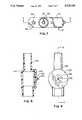
- FIG. 6is a cut-away view of the control module taken along lines 6--6 in FIG. 7;
- FIG. 7is a top view of the control module
- FIG. 8is a side view of a valve used in the preferred embodiment of the invention.
- FIG. 9is a front view of the valve illustrated in FIG. 8;
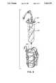
- FIG. 10is an illustration of a drainage straw used in one embodiment of the invention.
- the liner 22includes a flexible body 30.
- the flexible body 30has upper and lower portions 32 and 34 respectively.
- the upper portion 32is attached to the cover 24.
- the lower portion 34is attached to a bottom 36.
- the flexible body 30 and the bottom 36are shaped so as to generally conform to the walls 18 of the canister 12. Therefore, when the flexible body 30 and the bottom 36 are inserted into the cavity 20 as illustrated in FIG. 2, the liner 22 will fit snugly against the walls 18 of the cavity 20 of the canister 12 as illustrated in FIG. 4.
- the vacuum means which provides a relatively low vacuum to the inside of the liner 22must provide this vacuum at a constant relatively low level.
- the reason why the vacuum provided to the inside of the liner 22 must remain constantis that variations in the vacuum in the liner are transmitted to the patient 48 via a drainage tube 50 which is connected to a chest tube 52 as illustrated in FIG. 1.
- a high vacuumis applied to the inside of the liner 22 the same vacuum will be applied to the chest cavity of the patient 48. This can injure the patient's internal organs. Also, variations in vacuum can injure the patient's organs even if the vacuums are relatively low. Therefore, the high vacuum present in braided tube 46 is transmitted into control module 14 for transforming the variable high vacuum into a constant low vacuum.
- the control module 14is illustrated in greater detail in FIG. 6.
- the control module 14includes a first suction control chamber 54 for transforming the variable high vacuum into a constant low vacuum.
- the chamber 54is partially filled with a sterile fluid 56.
- the first chamber 54includes a first tube 58 that is located within the first chamber 54.
- the first tubehas first and second ends 60 and 62 respectively.
- the first end 60is immersed in the fluid 56 and the second end 62 extends above the top of the fluid 56 in the first chamber.
- the second end 62is attached to a lid 66 which covers the top 64 of the first chamber 54.
- the lid 66includes a port 68 which is located immediately above the top 64 of the first chamber 54.
- the second end 62 of the first tube 58is in sealed engagement with the port 68.
- the portis partially covered by a cap 70.
- a narrow air space 72exists between the cap 70 and the port 68 to allow atmospheric air pressure into tube 58.
- the high-vacuum source present in braided tube 46is attached to a cap 74 which is located on a high-vacuum port 76 on lid 66.
- the port 76provides a first path 78 between the high-vacuum source and a second chamber 80 in the control module 14.
- the lid 66 and the control module 14are shaped in such a way that when the lid 66 is placed on the control module 14 a second path 82 is formed between the first and second chambers 54 and 80.
- the second pathis a relatively narrow path that provides fluid communication between the first and second chambers 54 and 80.
- the high vacuum provided to the second chamber 80 through port 76is also transmitted to the first chamber 54.
- the high vacuumcauses atmospheric air present in tube 58 to be pulled through the first end 60 of the tube against the first column 56 of fluid.
- the resistive force of the water pressure against the air as it is drawn through the water columncreates a relatively low back pressure which is proportional to the height of the column of water.
- the vacuum-interface tube 96is in fluid communication with the inside of the liner 22. As discussed above, the vacuum present within the liner 22 is in fluid communication with the cavity of a patient 48 through tubes 50, 52. Therefore, the vacuum present in the first and second chambers 54, 80 of the control module 14 is also the same vacuum that is provided to the cavity of the patient 48.
- the purpose of the second chamber 80 of the control module 14is to provide a one-way fluid-based check valve to prevent gases from being delivered to the cavity of a patient 48. As will be discussed in greater detail below, gases are allowed to travel downwardly through the second tube 84, but are not allowed to travel from the upper portion 92 of the second chamber 80 through tube 84.
- the second chamber 80includes a second column of fluid 98 which is 2 cm. high in the preferred embodiment of the invention. The second column of fluid 98 acts to prevent gas present in the upper portion 92 of the second chamber 80 from entering the first end 86 of the second tube 84 in the event that the pressure in the upper portion 92 of the second chamber 80 is greater than the pressure in the patient's cavity.
- the fluid that is drawn up into the second tube 84rises and falls with each patient inhalation and exhalation whenever the system 10 is disconnected from a high-vacuum source. This fluid in the second tube 84 prevents any gas present in the second chamber from entering into the patient's chest cavity.
- the first tube 58includes a mesh net 100 covering the first end 60 of the first tube 58.
- the purpose of the mesh net 100is to cause air drawn through the first tube 58 into the first column 56 of fluid to be broken up into very fine bubbles. This act of breaking the air into fine bubbles reduces turbulence in the first column 56 of fluid. This is important because it prevents splashing of fluid 56 in the first chamber into the second chamber 80 through the second path 82.
- the lid 66 and the upper portion 102 of the control module between the first and second chambers 54, 80forms the second path 82.
- the lid 66 and the upper portion 102 of the control module 14form a gap with one another that creates the second path 82.
- the entrance to the second path 82 from the first chamber 54in the preferred embodiment, is no greater than 0.06 inches.
- the purpose of providing a very small entrance to the second path 82 from the first chamber 54is to reduce the possibility of fluid 56 in the first chamber 54 from entering the second chamber 80.
- the second path 82is a narrow torturous path. As illustrated in FIG. 6, the path 82 is a "U"-shaped path formed by "U"-shaped portion 104 in the upper portion 102 of the control module 14 which is parallel to a "U"-shaped portion 106 in lid 66.
- the second end 88 of the second tube 84is attached to a vacuum-interface port 90.
- a float valve 108is located inside the port 90.
- the float valve 108includes an inverted rubber cup 110 which is centered over the second end 88 of the second tube 84. As fluid in the second tube 84 reaches the inverted cup 110, the cup rises until a flexible gasket 112, located between the upper portion of the cup 110 and the vacuum-interface port 84, causes the float valve 108 to close.
- the lid 66includes at least one bleed orifice 114.
- a bleed orifice 114is located adjacent to the first path 78 on the lid 66.
- the purpose of the bleed orifice 114is to transform the high-source vacuum into an intermediate level vacuum which can be further reduced to a low vacuum by the first chamber 54 of the control module 14. By allowing small amounts of air to enter into the first and second chambers 54, 80 through the bleed orifice 114, the vacuum from the high-vacuum source is partially reduced.
- the high vacuum from the high-vacuum sourceis also partially reduced through the use of an in-line orifice 116 located in the high-vacuum cap 74.
- the relatively small in-line orifice 116causes the high vacuum from the high-vacuum source to be reduced to a lower vacuum since the bleed orifice 114 pulls air into the upper portions of the first and second chambers as a high vacuum is applied to the in-line orifice 116. Therefore, the in-line orifice 116 and the bleed orifice 114 act in conjunction to produce an intermediate level vacuum which is then reduced to a low vacuum as discussed above.
- the first column of fluid 56 in the first chamber 54is formed using no greater than 220 cc of fluid to provide 20 cm. H 2 O vacuum in the first and second chambers 54, 80 when the high-vacuum source provides up to 14.7 psi vacuum to the first path 78. This is a relatively small amount of fluid compared to other systems used in the past. This small amount of fluid is able to provide a reduction in vacuum due to the use of the bleed orifice 114 and the in-line orifice 116 to step down the vacuum from the high-vacuum source to an intermediate level vacuum.
- a vacuum-sensing valve 118is provided in series between the low-vacuum source 120 of the control module 14 and the inside 122 of the liner 22.
- the valveis designed to open the inside of the liner to atmospheric pressure when the vacuum inside 122 of the liner 22 exceeds a pre-determined value.
- the pre-determined valueis 40 cm. H 2 O. This prevents undesirably high vacuums from being applied to the patient's chest cavity.
- FIG. 8is a cut-away view of the vacuum-sensing valve 118.
- the valveincludes a valve body 124, a seat 126 and an elastomeric umbrella 128.
- the seat 126 of the vacuum-sensing valve 118includes a plurality of openings 130 to allow atmospheric air to enter the valve body 124 when the vacuum within the valve body exceeds a pre-determined level.
- the edges 132 of the elastomeric umbrella 128will be drawn toward the center of the valve body 124 and away from the valve seat 126.
- the edges 132 of the elastomeric umbrella 128are in their normal position, the edges 132 are biased against the openings 130.
- the edgeswill withdraw into the valve body 124 to allow atmospheric air into the valve body. This prevents undesirably high vacuums which may be present inside the liner 22 to be applied to the chest cavity of a patient.
- the system 10includes a drainage means 134 for providing fluid communication between the inside 122 of the liner 22 and the chest cavity of the patient 48.
- the drainage means 134includes a drainage tube 50 which is connected to a patient port 136 and the cover 24 of the system 10.
- the patient port 136has a porous filter 138 attached to collect large particle-size debris which may be drawn into the system from the patient's chest cavity. This filter prevents this debris from being mixed with fluid that is collected in the liner 22 for later re-infusion back into the patient.
- the filterhas a pore size of between 120 and 130 microns. The filter is located inside the liner 22 immediately under the patient port 136.
- the cover 24also includes an interface port 140 to allow removal of fluids from the liner 22 for further processing or re-infusion back into the patient without removing the linear from the cannister.
- the interface port 140is not in use, the port is covered with a cap 142.
- a sterile straw 144is inserted into the liner 22 to withdraw fluids from the bottom of the liner. The straw is illustrated in FIG. 10 in its pouch.
- the straw 144has first and second ends 146, 148 respectively.
- the first end of the strawcan be inserted through the interface port 140 down into the bottom of the liner 22.
- the second end 148 of the straw 144is attached to an elbow 150.
- the elbowincludes first and second ends 152, 154 respectively.
- the first end of the elbowincludes a skirt 156 which is designed to fit snugly around the outside diameter of the interface port 140 to firmly secure the straw onto the interface port 140. Accordingly, the skirt 156 consists of a ring which can be concentrically placed about the interface port 140.
- the second end 154 of the elbow 150has a tapered port for connection to tubing of various inside diameters.
- This portis normally attached to such tubing to allow fluid within the liner to be drawn into the tubing either for re-in-fusion back into the patient or for further processing. For example, in some instances, it may be desirable to send the fluid through a cell washer to remove the red cells from the fluid and discard any other debris that may be present in the fluid. The red cells may then be used by the patient.
- one feature of this inventionis to provide a sterile system in which the straw is maintained in a sterile, thin-walled flexible sleeve 158 prior to insertion into the liner 22.
- the sleevecompletely covers the straw.
- the sleevehas first and second ends 160 and 162 respectively in the preferred embodiment, the ends are simply folded inward towards the sleeve and taped shut.
- medical personnelcan open the first end 160 of the sleeve 158 to expose the first end 146 of the straw 144.
- the first end 160 of the sleeve 158can be pushed back toward the elbow to allow the first end 146 of the straw 144 to be inserted into the liner 22 while the second end 148 of the straw remains covered by the sleeve 158.
- the sleevecan be completely removed to allow the second end 154 of the elbow 150 to be attached to a tube as discussed above.
- the first end 160 of the sleeve 158is opened simply by forcefully puncturing the sleeve with the first end 146 of the straw 144.
- the entire sleeve 158is enclosed in an outer peelable outer pouch 164.
- the outer pouchcan be opened by a "non-sterile" medical personnel to present the sterile sleeve 158 and straw 144 to a "sterile" nurse.
- FIG. 11is a perspective view of a tray 166 used to store and transport the control module 14.
- the tray 166includes a storage means 168 for maintaining the control module 14 in a horizontal position within the tray as the module is being transported.
- the tray 166also includes a holding means 170 for maintaining the control module 14 in a vertical position in the tray 168 to allow the control module 14 to be partially filled with sterile fluid. This is illustrated in FIG. 12.
- the holding meansincludes a pair of indentions 172 which form a slot 174 for maintaining the control module 14 in a vertical position.
- the storage means 168is a pre-formed plastic container 176 having a top opening 178 that is sealed with a lid 180 which can be peeled away from the top opening to expose the inside of the container 176.
- the preformed container 176includes a bottom and side walls which generally conform to the overall outer shape of the control module 14 when the control module 14 is in a horizontal position. Thus, the control module 14 can be snugly placed inside the container 176 to be transported.
- the tray 166 described hereinhas several advantages. First, the use of the tray to maintain the control module in an upright position as the module is being filled acts as a sterile field around the control module since the inside of the tray is sterile prior to peeling back the lid 180 from the top 178 of the tray. Second, the tray 166 acts as a fluid collection means to collect any spills which may occur as the module is being filled. This is of great value to operating room personnel.
Landscapes
- Health & Medical Sciences (AREA)
- Heart & Thoracic Surgery (AREA)
- Vascular Medicine (AREA)
- Engineering & Computer Science (AREA)
- Anesthesiology (AREA)
- Biomedical Technology (AREA)
- Hematology (AREA)
- Life Sciences & Earth Sciences (AREA)
- Animal Behavior & Ethology (AREA)
- General Health & Medical Sciences (AREA)
- Public Health (AREA)
- Veterinary Medicine (AREA)
- Pulmonology (AREA)
- External Artificial Organs (AREA)
Abstract
Description
Claims (1)
Priority Applications (1)
| Application Number | Priority Date | Filing Date | Title |
|---|---|---|---|
| US07/660,506US5223228A (en) | 1991-02-25 | 1991-02-25 | Tray for autotransfusion module |
Applications Claiming Priority (1)
| Application Number | Priority Date | Filing Date | Title |
|---|---|---|---|
| US07/660,506US5223228A (en) | 1991-02-25 | 1991-02-25 | Tray for autotransfusion module |
Publications (1)
| Publication Number | Publication Date |
|---|---|
| US5223228Atrue US5223228A (en) | 1993-06-29 |
Family
ID=24649815
Family Applications (1)
| Application Number | Title | Priority Date | Filing Date |
|---|---|---|---|
| US07/660,506Expired - Fee RelatedUS5223228A (en) | 1991-02-25 | 1991-02-25 | Tray for autotransfusion module |
Country Status (1)
| Country | Link |
|---|---|
| US (1) | US5223228A (en) |
Cited By (9)
| Publication number | Priority date | Publication date | Assignee | Title |
|---|---|---|---|---|
| EP1059094A1 (en)* | 1998-01-22 | 2000-12-13 | Fresenius AG | Blood collection device |
| US20060122575A1 (en)* | 2002-06-11 | 2006-06-08 | Akio Wakabayashi | System and efficient drainage of body cavity |
| CN104667360A (en)* | 2015-02-11 | 2015-06-03 | 昆山韦睿医疗科技有限公司 | Negative-pressure wound treatment equipment |
| EP2571558B1 (en) | 2010-05-18 | 2016-06-29 | KCI Licensing, Inc. | Reduced-pressure canisters and methods for recycling |
| WO2019003134A1 (en)* | 2017-06-28 | 2019-01-03 | 4D Pharma León, S.L.U. | Method and apparatus for lining a chamber |
| US20190091459A1 (en)* | 2017-09-22 | 2019-03-28 | Critical Innovations, LLC | Percutaneous access pathway system |
| US10864356B2 (en) | 2013-12-26 | 2020-12-15 | Critical Innovations, LLC | Percutaneous access pathway system and method |
| US11364326B2 (en) | 2012-08-07 | 2022-06-21 | Critical Innovations, LLC | Method and device for simultaneously documenting and treating tension pneumothorax and/or hemothorax |
| US12036351B2 (en) | 2010-04-16 | 2024-07-16 | Solventum Intellectual Properties Company | Dressings and methods for treating a tissue site on a patient |
Citations (57)
| Publication number | Priority date | Publication date | Assignee | Title |
|---|---|---|---|---|
| US3363627A (en)* | 1966-10-20 | 1968-01-16 | Deknatel Inc | Underwater drainage apparatus |
| US3683913A (en)* | 1970-10-05 | 1972-08-15 | Deknatel Inc | Underwater drainage apparatus with air flow meters |
| US3866608A (en)* | 1973-10-23 | 1975-02-18 | Sorenson Research Co | Aseptic suction collection system and method |
| US3896733A (en)* | 1973-10-18 | 1975-07-29 | Pall Corp | Autotransfusion apparatus |
| US3993067A (en)* | 1975-04-24 | 1976-11-23 | Sherwood Medical Industries Inc. | Autotransfusion device |
| US4006745A (en)* | 1975-05-22 | 1977-02-08 | Sorenson Research Co., Inc. | Autologous transfusion system and method |
| US4014329A (en)* | 1975-07-03 | 1977-03-29 | The Rochester General Hospital | Method and apparatus for autotransfusion of blood |
| US4015603A (en)* | 1975-10-10 | 1977-04-05 | Deknatel Inc. | Surgical drainage system with pressure indicator |
| US4018224A (en)* | 1976-04-07 | 1977-04-19 | Deknatel, Inc. | Underwater drainage device with dual collection chambers |
| US4033345A (en)* | 1975-11-13 | 1977-07-05 | Sorenson Research Co., Inc. | Autologous transfusion filter system and method |
| US4047526A (en)* | 1975-05-22 | 1977-09-13 | Sorenson Research Co., Inc. | Autologous blood system and method |
| US4058123A (en)* | 1975-10-01 | 1977-11-15 | International Paper Company | Combined irrigator and evacuator for closed wounds |
| US4105031A (en)* | 1975-10-10 | 1978-08-08 | Deknatel, Inc. | Attachable expansion chamber for pleural drainage device |
| US4111204A (en)* | 1976-10-07 | 1978-09-05 | C. R. Bard, Inc. | Suction collection system |
| US4112948A (en)* | 1976-05-07 | 1978-09-12 | Deknatel, Inc. | Surgical drainage system with pressure indicator and enclosed source of liquid |
| US4112949A (en)* | 1976-11-15 | 1978-09-12 | Howmedica Inc. | Apparatus for collecting body fluid |
| USRE29877E (en)* | 1972-07-10 | 1979-01-09 | Deknatel Inc. | Valved underwater drainage apparatus |
| US4195633A (en)* | 1977-11-07 | 1980-04-01 | International Paper Company | Chest drainage system with visual float means |
| US4278089A (en)* | 1978-11-09 | 1981-07-14 | Howmedica, Inc. | Wound drainage device |
| US4289158A (en)* | 1976-09-10 | 1981-09-15 | C. R. Bard, Inc. | Suction control apparatus |
| US4296748A (en)* | 1979-06-27 | 1981-10-27 | Bioresearch Inc. | Underwater drainage apparatus with separable suction control chamber |
| US4402407A (en)* | 1980-12-16 | 1983-09-06 | Maly George P | Sterilization chest |
| US4419093A (en)* | 1980-01-21 | 1983-12-06 | American Hospital Supply Corporation | Method of receiving and disposing of fluids from the body |
| US4425125A (en)* | 1980-02-11 | 1984-01-10 | Bioresearch Inc. | Two-chamber underwater drainage apparatus with oneway outflow valve |
| US4439189A (en)* | 1981-06-18 | 1984-03-27 | Bentley Laboratories, Inc. | Pleural drainage system |
| US4443220A (en)* | 1982-03-16 | 1984-04-17 | Hauer Jerome Maurice | Blood collection and transfer apparatus |
| US4445884A (en)* | 1981-08-14 | 1984-05-01 | Bioresearch Inc. | Air purge unit for auto transfusion apparatus |
| US4453937A (en)* | 1981-08-05 | 1984-06-12 | Bioresearch Inc. | Drainage device with flow meter |
| US4458705A (en)* | 1982-12-27 | 1984-07-10 | Cawood Charles David | Tray and basin combination |
| US4465483A (en)* | 1982-06-08 | 1984-08-14 | Snyder Laboratories, Inc. | Modular drainage apparatus |
| US4468226A (en)* | 1982-06-08 | 1984-08-28 | Bioresearch Inc. | Surgical drainage apparatus with incremental suction control and indication |
| US4469484A (en)* | 1982-06-08 | 1984-09-04 | Bio Research Inc. | Surgical drainage device with automatic negative pressure relief system |
| US4484908A (en)* | 1981-04-21 | 1984-11-27 | Bioresearch Inc. | Method for relieving excess negativity in a drainage device |
| US4487606A (en)* | 1983-01-31 | 1984-12-11 | Becton, Dickinson And Company | Suction canister with shut-off valve and smoke filter |
| US4500308A (en)* | 1982-11-16 | 1985-02-19 | Bioresearch Inc. | Autotransfusion device with twisted collection bag |
| US4507120A (en)* | 1982-04-21 | 1985-03-26 | Paradis Joseph R | Suction canister with corrugated adjustable suction inlet |
| US4515283A (en)* | 1981-11-13 | 1985-05-07 | Hiro Suzuki | Bung for jars |
| US4516973A (en)* | 1983-03-14 | 1985-05-14 | Becton, Dickinson And Company | One-piece disposable collection bag having a rigid cover for a suction canister unit |
| US4519796A (en)* | 1983-06-17 | 1985-05-28 | Russo Ronald D | Thoracic drainage device |
| US4522623A (en)* | 1981-12-21 | 1985-06-11 | Lauterjung F G | Suction bottle for medicinal purposes |
| US4540413A (en)* | 1983-06-17 | 1985-09-10 | Russo Ronald D | Cardiopulmonary drainage collector with blood transfer adapter |
| US4544370A (en)* | 1982-05-24 | 1985-10-01 | C. R. Bard, Inc. | Air leak detection system for chest fluid collection bottles and blow-out prevention baffle |
| US4564359A (en)* | 1983-02-10 | 1986-01-14 | Ruehland Dieter | Autotransfusion apparatus |
| US4573992A (en)* | 1982-05-17 | 1986-03-04 | Solco Basel Ag | Apparatus for receiving and reinfusing blood |
| US4578060A (en)* | 1983-07-20 | 1986-03-25 | Howmedica, Inc. | Wound drainage device |
| US4619647A (en)* | 1984-05-04 | 1986-10-28 | Bioresearch Inc. | Surgical drainage apparatus |
| US4631050A (en)* | 1985-09-24 | 1986-12-23 | Reed Charles C | Autotransfusion system and method |
| US4650477A (en)* | 1982-10-15 | 1987-03-17 | Sorenson Research Co. Inc. | Suction drainage apparatus |
| US4772256A (en)* | 1986-11-07 | 1988-09-20 | Lantech, Inc. | Methods and apparatus for autotransfusion of blood |
| US4781707A (en)* | 1986-02-18 | 1988-11-01 | Boehringer Laboratories | Process and apparatus for collecting blood from a body cavity for autotransfusion |
| US4798578A (en)* | 1987-02-13 | 1989-01-17 | Sherwood Medical Company | Autotransfusion device |
| US4838872A (en)* | 1987-02-13 | 1989-06-13 | Sherwood Medical Company | Blood collection device |
| US4840771A (en)* | 1986-09-22 | 1989-06-20 | Becton Dickinson & Company | Incubator for reagents |
| US4846800A (en)* | 1987-10-14 | 1989-07-11 | Kenneth Ouriel | Two chambered autotransfuser device and method of use |
| US4857042A (en)* | 1988-03-16 | 1989-08-15 | Sherwood Medical Company | Body fluid collection device |
| US4898572A (en)* | 1986-06-24 | 1990-02-06 | Futur-Quotidien S.A. | Autotransfuser |
| US4923438A (en)* | 1988-07-18 | 1990-05-08 | Pfizer Hospital Products Group, Inc. | Blood recovery system and method |
- 1991
- 1991-02-25USUS07/660,506patent/US5223228A/ennot_activeExpired - Fee Related
Patent Citations (59)
| Publication number | Priority date | Publication date | Assignee | Title |
|---|---|---|---|---|
| US3363627A (en)* | 1966-10-20 | 1968-01-16 | Deknatel Inc | Underwater drainage apparatus |
| US3683913A (en)* | 1970-10-05 | 1972-08-15 | Deknatel Inc | Underwater drainage apparatus with air flow meters |
| USRE29877E (en)* | 1972-07-10 | 1979-01-09 | Deknatel Inc. | Valved underwater drainage apparatus |
| US3896733A (en)* | 1973-10-18 | 1975-07-29 | Pall Corp | Autotransfusion apparatus |
| US3866608A (en)* | 1973-10-23 | 1975-02-18 | Sorenson Research Co | Aseptic suction collection system and method |
| US3993067A (en)* | 1975-04-24 | 1976-11-23 | Sherwood Medical Industries Inc. | Autotransfusion device |
| US4047526A (en)* | 1975-05-22 | 1977-09-13 | Sorenson Research Co., Inc. | Autologous blood system and method |
| US4006745A (en)* | 1975-05-22 | 1977-02-08 | Sorenson Research Co., Inc. | Autologous transfusion system and method |
| US4014329A (en)* | 1975-07-03 | 1977-03-29 | The Rochester General Hospital | Method and apparatus for autotransfusion of blood |
| US4058123A (en)* | 1975-10-01 | 1977-11-15 | International Paper Company | Combined irrigator and evacuator for closed wounds |
| US4112947A (en)* | 1975-10-01 | 1978-09-12 | International Paper Company | Combined irrigator and evacuator for closed wounds |
| US4105031A (en)* | 1975-10-10 | 1978-08-08 | Deknatel, Inc. | Attachable expansion chamber for pleural drainage device |
| US4015603A (en)* | 1975-10-10 | 1977-04-05 | Deknatel Inc. | Surgical drainage system with pressure indicator |
| US4033345A (en)* | 1975-11-13 | 1977-07-05 | Sorenson Research Co., Inc. | Autologous transfusion filter system and method |
| US4018224A (en)* | 1976-04-07 | 1977-04-19 | Deknatel, Inc. | Underwater drainage device with dual collection chambers |
| US4112948A (en)* | 1976-05-07 | 1978-09-12 | Deknatel, Inc. | Surgical drainage system with pressure indicator and enclosed source of liquid |
| US4289158A (en)* | 1976-09-10 | 1981-09-15 | C. R. Bard, Inc. | Suction control apparatus |
| US4111204B1 (en)* | 1976-10-07 | 1983-01-18 | ||
| US4111204A (en)* | 1976-10-07 | 1978-09-05 | C. R. Bard, Inc. | Suction collection system |
| US4112949A (en)* | 1976-11-15 | 1978-09-12 | Howmedica Inc. | Apparatus for collecting body fluid |
| US4195633A (en)* | 1977-11-07 | 1980-04-01 | International Paper Company | Chest drainage system with visual float means |
| US4278089A (en)* | 1978-11-09 | 1981-07-14 | Howmedica, Inc. | Wound drainage device |
| US4296748A (en)* | 1979-06-27 | 1981-10-27 | Bioresearch Inc. | Underwater drainage apparatus with separable suction control chamber |
| US4419093A (en)* | 1980-01-21 | 1983-12-06 | American Hospital Supply Corporation | Method of receiving and disposing of fluids from the body |
| US4425125A (en)* | 1980-02-11 | 1984-01-10 | Bioresearch Inc. | Two-chamber underwater drainage apparatus with oneway outflow valve |
| US4402407A (en)* | 1980-12-16 | 1983-09-06 | Maly George P | Sterilization chest |
| US4484908A (en)* | 1981-04-21 | 1984-11-27 | Bioresearch Inc. | Method for relieving excess negativity in a drainage device |
| US4439189A (en)* | 1981-06-18 | 1984-03-27 | Bentley Laboratories, Inc. | Pleural drainage system |
| US4453937A (en)* | 1981-08-05 | 1984-06-12 | Bioresearch Inc. | Drainage device with flow meter |
| US4445884A (en)* | 1981-08-14 | 1984-05-01 | Bioresearch Inc. | Air purge unit for auto transfusion apparatus |
| US4515283A (en)* | 1981-11-13 | 1985-05-07 | Hiro Suzuki | Bung for jars |
| US4522623A (en)* | 1981-12-21 | 1985-06-11 | Lauterjung F G | Suction bottle for medicinal purposes |
| US4443220A (en)* | 1982-03-16 | 1984-04-17 | Hauer Jerome Maurice | Blood collection and transfer apparatus |
| US4507120A (en)* | 1982-04-21 | 1985-03-26 | Paradis Joseph R | Suction canister with corrugated adjustable suction inlet |
| US4573992A (en)* | 1982-05-17 | 1986-03-04 | Solco Basel Ag | Apparatus for receiving and reinfusing blood |
| US4544370A (en)* | 1982-05-24 | 1985-10-01 | C. R. Bard, Inc. | Air leak detection system for chest fluid collection bottles and blow-out prevention baffle |
| US4465483A (en)* | 1982-06-08 | 1984-08-14 | Snyder Laboratories, Inc. | Modular drainage apparatus |
| US4468226A (en)* | 1982-06-08 | 1984-08-28 | Bioresearch Inc. | Surgical drainage apparatus with incremental suction control and indication |
| US4469484A (en)* | 1982-06-08 | 1984-09-04 | Bio Research Inc. | Surgical drainage device with automatic negative pressure relief system |
| US4650477A (en)* | 1982-10-15 | 1987-03-17 | Sorenson Research Co. Inc. | Suction drainage apparatus |
| US4500308A (en)* | 1982-11-16 | 1985-02-19 | Bioresearch Inc. | Autotransfusion device with twisted collection bag |
| US4458705A (en)* | 1982-12-27 | 1984-07-10 | Cawood Charles David | Tray and basin combination |
| US4487606A (en)* | 1983-01-31 | 1984-12-11 | Becton, Dickinson And Company | Suction canister with shut-off valve and smoke filter |
| US4564359A (en)* | 1983-02-10 | 1986-01-14 | Ruehland Dieter | Autotransfusion apparatus |
| US4516973A (en)* | 1983-03-14 | 1985-05-14 | Becton, Dickinson And Company | One-piece disposable collection bag having a rigid cover for a suction canister unit |
| US4519796A (en)* | 1983-06-17 | 1985-05-28 | Russo Ronald D | Thoracic drainage device |
| US4540413A (en)* | 1983-06-17 | 1985-09-10 | Russo Ronald D | Cardiopulmonary drainage collector with blood transfer adapter |
| US4578060A (en)* | 1983-07-20 | 1986-03-25 | Howmedica, Inc. | Wound drainage device |
| US4619647A (en)* | 1984-05-04 | 1986-10-28 | Bioresearch Inc. | Surgical drainage apparatus |
| US4631050A (en)* | 1985-09-24 | 1986-12-23 | Reed Charles C | Autotransfusion system and method |
| US4781707A (en)* | 1986-02-18 | 1988-11-01 | Boehringer Laboratories | Process and apparatus for collecting blood from a body cavity for autotransfusion |
| US4898572A (en)* | 1986-06-24 | 1990-02-06 | Futur-Quotidien S.A. | Autotransfuser |
| US4840771A (en)* | 1986-09-22 | 1989-06-20 | Becton Dickinson & Company | Incubator for reagents |
| US4772256A (en)* | 1986-11-07 | 1988-09-20 | Lantech, Inc. | Methods and apparatus for autotransfusion of blood |
| US4838872A (en)* | 1987-02-13 | 1989-06-13 | Sherwood Medical Company | Blood collection device |
| US4798578A (en)* | 1987-02-13 | 1989-01-17 | Sherwood Medical Company | Autotransfusion device |
| US4846800A (en)* | 1987-10-14 | 1989-07-11 | Kenneth Ouriel | Two chambered autotransfuser device and method of use |
| US4857042A (en)* | 1988-03-16 | 1989-08-15 | Sherwood Medical Company | Body fluid collection device |
| US4923438A (en)* | 1988-07-18 | 1990-05-08 | Pfizer Hospital Products Group, Inc. | Blood recovery system and method |
Cited By (18)
| Publication number | Priority date | Publication date | Assignee | Title |
|---|---|---|---|---|
| US6200276B1 (en) | 1998-01-22 | 2001-03-13 | Fresenius Ag | Blood collecting device |
| EP1059094A1 (en)* | 1998-01-22 | 2000-12-13 | Fresenius AG | Blood collection device |
| US20060122575A1 (en)* | 2002-06-11 | 2006-06-08 | Akio Wakabayashi | System and efficient drainage of body cavity |
| US8439893B2 (en)* | 2002-06-11 | 2013-05-14 | Medela Holding Ag | System and method for efficient drainage of body cavity |
| US12036351B2 (en) | 2010-04-16 | 2024-07-16 | Solventum Intellectual Properties Company | Dressings and methods for treating a tissue site on a patient |
| EP2571558B1 (en) | 2010-05-18 | 2016-06-29 | KCI Licensing, Inc. | Reduced-pressure canisters and methods for recycling |
| US12419999B2 (en) | 2012-08-07 | 2025-09-23 | Critical Innovations, LLC | Method and device for simultaneously documenting and treating tension pneumothorax and/or hemothorax |
| US11364326B2 (en) | 2012-08-07 | 2022-06-21 | Critical Innovations, LLC | Method and device for simultaneously documenting and treating tension pneumothorax and/or hemothorax |
| US12005165B2 (en) | 2012-08-07 | 2024-06-11 | Critical Innovations, LLC | Method and device for simultaneously documenting and treating tension pneumothorax and/or hemothorax |
| US11865281B2 (en) | 2013-12-26 | 2024-01-09 | Critical Innovations, LLC | Percutaneous access pathway system and method |
| US12263320B2 (en) | 2013-12-26 | 2025-04-01 | Critical Innovations Llc | Percutaneous access pathway system and method |
| US10864356B2 (en) | 2013-12-26 | 2020-12-15 | Critical Innovations, LLC | Percutaneous access pathway system and method |
| CN104667360A (en)* | 2015-02-11 | 2015-06-03 | 昆山韦睿医疗科技有限公司 | Negative-pressure wound treatment equipment |
| WO2019003134A1 (en)* | 2017-06-28 | 2019-01-03 | 4D Pharma León, S.L.U. | Method and apparatus for lining a chamber |
| US11406809B2 (en)* | 2017-09-22 | 2022-08-09 | Critical Innovations, LLC | Percutaneous access pathway system |
| US10814119B2 (en)* | 2017-09-22 | 2020-10-27 | Critical Innovations, LLC | Percutaneous access pathway system |
| US20190091459A1 (en)* | 2017-09-22 | 2019-03-28 | Critical Innovations, LLC | Percutaneous access pathway system |
| US12324894B2 (en) | 2017-09-22 | 2025-06-10 | Critical Innovations Llc | Percutaneous access pathway system |
Similar Documents
| Publication | Publication Date | Title |
|---|---|---|
| US5382244A (en) | Stand alone control module | |
| US5149325A (en) | Vacuum system for auto transfusion device | |
| US5401262A (en) | Fluid recovery system | |
| US5019059A (en) | Apparatus and method for collecting body fluids | |
| US4988342A (en) | Improved fluid recovery system | |
| US5286262A (en) | Multipurpose collection vessel | |
| US5102404A (en) | Apparatus and method for collecting body fluids | |
| US3866608A (en) | Aseptic suction collection system and method | |
| US4675010A (en) | Thoracic drainage collection system and method | |
| US4402687A (en) | Suction collection system | |
| US5397299A (en) | Fluid recovery system with improvements molded in body | |
| US5931821A (en) | Chest drainage unit with controlled automatic excess negativity relief feature | |
| US4312351A (en) | Drainage device with separate outflow chamber | |
| US5223228A (en) | Tray for autotransfusion module | |
| US5114416A (en) | Fluid recovery system having an improved float valve | |
| US6183453B1 (en) | Blood evacuation container with blood spike nesting feature | |
| EP1389139B1 (en) | Sampling port for a drainage device | |
| CA1304645C (en) | Apparatus and method for collecting body fluids | |
| CA1235622A (en) | Drainage device with diverted gas flow path | |
| US6659987B2 (en) | Fill spout for a drainage device | |
| AU723155B2 (en) | Drainage unit with controlled negativity relief feature | |
| AU2002228908A1 (en) | Fill spout for a drainage device | |
| CA2425865C (en) | Drainage unit with controlled negativity relief feature |
Legal Events
| Date | Code | Title | Description |
|---|---|---|---|
| FEPP | Fee payment procedure | Free format text:PAYOR NUMBER ASSIGNED (ORIGINAL EVENT CODE: ASPN); ENTITY STATUS OF PATENT OWNER: LARGE ENTITY | |
| AS | Assignment | Owner name:BAXTER INTERNATIONAL INC., ILLINOIS Free format text:ASSIGNMENT OF ASSIGNORS INTEREST;ASSIGNORS:TELANG, ANIL M.;RIVERA, DAVID A.;JOHNSON, MICHAEL DARVEY;REEL/FRAME:006616/0364 Effective date:19930218 | |
| FPAY | Fee payment | Year of fee payment:4 | |
| AS | Assignment | Owner name:ALLEGIANCE CORPORATION, ILLINOIS Free format text:ASSIGNMENT OF ASSIGNORS INTEREST;ASSIGNOR:BAXTER INTERNATIONAL, INC.;REEL/FRAME:009227/0184 Effective date:19960930 | |
| FEPP | Fee payment procedure | Free format text:PAYOR NUMBER ASSIGNED (ORIGINAL EVENT CODE: ASPN); ENTITY STATUS OF PATENT OWNER: LARGE ENTITY Free format text:PAYER NUMBER DE-ASSIGNED (ORIGINAL EVENT CODE: RMPN); ENTITY STATUS OF PATENT OWNER: LARGE ENTITY | |
| REMI | Maintenance fee reminder mailed | ||
| LAPS | Lapse for failure to pay maintenance fees | ||
| FP | Lapsed due to failure to pay maintenance fee | Effective date:20010629 | |
| STCH | Information on status: patent discontinuation | Free format text:PATENT EXPIRED DUE TO NONPAYMENT OF MAINTENANCE FEES UNDER 37 CFR 1.362 |