US5222808A - Capillary mixing device - Google Patents
Capillary mixing deviceDownload PDFInfo
- Publication number
- US5222808A US5222808AUS07/867,155US86715592AUS5222808AUS 5222808 AUS5222808 AUS 5222808AUS 86715592 AUS86715592 AUS 86715592AUS 5222808 AUS5222808 AUS 5222808A
- Authority
- US
- United States
- Prior art keywords
- chamber
- capillary
- particles
- mixing
- magnetic
- Prior art date
- Legal status (The legal status is an assumption and is not a legal conclusion. Google has not performed a legal analysis and makes no representation as to the accuracy of the status listed.)
- Expired - Lifetime
Links
- 238000002156mixingMethods0.000titleclaimsabstractdescription119
- 239000002245particleSubstances0.000claimsabstractdescription88
- 230000005291magnetic effectEffects0.000claimsabstractdescription83
- 239000007788liquidSubstances0.000claimsabstractdescription42
- 230000001939inductive effectEffects0.000claimsabstractdescription11
- 230000033001locomotionEffects0.000claimsdescription35
- 239000003153chemical reaction reagentSubstances0.000claimsdescription27
- SZVJSHCCFOBDDC-UHFFFAOYSA-Niron(II,III) oxideInorganic materialsO=[Fe]O[Fe]O[Fe]=OSZVJSHCCFOBDDC-UHFFFAOYSA-N0.000claimsdescription15
- 239000000203mixtureSubstances0.000claimsdescription15
- 238000000034methodMethods0.000claimsdescription14
- AJCDFVKYMIUXCR-UHFFFAOYSA-Noxobarium;oxo(oxoferriooxy)ironChemical compound[Ba]=O.O=[Fe]O[Fe]=O.O=[Fe]O[Fe]=O.O=[Fe]O[Fe]=O.O=[Fe]O[Fe]=O.O=[Fe]O[Fe]=O.O=[Fe]O[Fe]=OAJCDFVKYMIUXCR-UHFFFAOYSA-N0.000claimsdescription6
- 238000001514detection methodMethods0.000claimsdescription5
- 239000011248coating agentSubstances0.000claimsdescription3
- 238000000576coating methodMethods0.000claimsdescription3
- 230000000694effectsEffects0.000claimsdescription2
- 230000005381magnetic domainEffects0.000claimsdescription2
- 230000003287optical effectEffects0.000claimsdescription2
- 230000000717retained effectEffects0.000abstractdescription3
- 210000004369bloodAnatomy0.000description16
- 239000008280bloodSubstances0.000description16
- 239000012530fluidSubstances0.000description16
- 238000003556assayMethods0.000description12
- 238000004458analytical methodMethods0.000description11
- 239000006249magnetic particleSubstances0.000description9
- HVYWMOMLDIMFJA-DPAQBDIFSA-NcholesterolChemical compoundC1C=C2C[C@@H](O)CC[C@]2(C)[C@@H]2[C@@H]1[C@@H]1CC[C@H]([C@H](C)CCCC(C)C)[C@@]1(C)CC2HVYWMOMLDIMFJA-DPAQBDIFSA-N0.000description8
- 108010023302HDL CholesterolProteins0.000description7
- XEEYBQQBJWHFJM-UHFFFAOYSA-NIronChemical compound[Fe]XEEYBQQBJWHFJM-UHFFFAOYSA-N0.000description6
- UQSXHKLRYXJYBZ-UHFFFAOYSA-NIron oxideChemical compound[Fe]=OUQSXHKLRYXJYBZ-UHFFFAOYSA-N0.000description6
- 238000009472formulationMethods0.000description6
- 239000000463materialSubstances0.000description6
- 230000009471actionEffects0.000description5
- 238000004090dissolutionMethods0.000description5
- 238000001556precipitationMethods0.000description5
- 239000000725suspensionSubstances0.000description5
- 235000012000cholesterolNutrition0.000description4
- 238000013461designMethods0.000description4
- 239000000975dyeSubstances0.000description4
- 238000012795verificationMethods0.000description4
- 229910000831SteelInorganic materials0.000description3
- 238000002835absorbanceMethods0.000description3
- 210000004027cellAnatomy0.000description3
- 238000006243chemical reactionMethods0.000description3
- 230000006870functionEffects0.000description3
- 230000002949hemolytic effectEffects0.000description3
- 229910052742ironInorganic materials0.000description3
- 230000009467reductionEffects0.000description3
- 239000010959steelSubstances0.000description3
- 238000003756stirringMethods0.000description3
- 238000012360testing methodMethods0.000description3
- XLYOFNOQVPJJNP-UHFFFAOYSA-NwaterSubstancesOXLYOFNOQVPJJNP-UHFFFAOYSA-N0.000description3
- 108091003079Bovine Serum AlbuminProteins0.000description2
- 206010018910HaemolysisDiseases0.000description2
- 108010007622LDL LipoproteinsProteins0.000description2
- 239000002202Polyethylene glycolSubstances0.000description2
- 229920000122acrylonitrile butadiene styrenePolymers0.000description2
- 239000000654additiveSubstances0.000description2
- 239000012491analyteSubstances0.000description2
- 230000004888barrier functionEffects0.000description2
- 229910052796boronInorganic materials0.000description2
- 229940098773bovine serum albuminDrugs0.000description2
- 230000008859changeEffects0.000description2
- 230000009089cytolysisEffects0.000description2
- 230000007423decreaseEffects0.000description2
- 238000009792diffusion processMethods0.000description2
- 238000010790dilutionMethods0.000description2
- 239000012895dilutionSubstances0.000description2
- 238000009826distributionMethods0.000description2
- 239000007789gasSubstances0.000description2
- 230000005484gravityEffects0.000description2
- 230000008588hemolysisEffects0.000description2
- 230000002209hydrophobic effectEffects0.000description2
- 239000000696magnetic materialSubstances0.000description2
- 239000002609mediumSubstances0.000description2
- 230000035699permeabilityEffects0.000description2
- 229920003023plasticPolymers0.000description2
- 239000004033plasticSubstances0.000description2
- 229920001223polyethylene glycolPolymers0.000description2
- 239000000843powderSubstances0.000description2
- 230000001376precipitating effectEffects0.000description2
- 238000002360preparation methodMethods0.000description2
- 230000008569processEffects0.000description2
- 239000000243solutionSubstances0.000description2
- ZOXJGFHDIHLPTG-UHFFFAOYSA-NBoronChemical compound[B]ZOXJGFHDIHLPTG-UHFFFAOYSA-N0.000description1
- 101100184147Caenorhabditis elegans mix-1 geneProteins0.000description1
- 206010053567CoagulopathiesDiseases0.000description1
- 108010010234HDL LipoproteinsProteins0.000description1
- 102000001554HemoglobinsHuman genes0.000description1
- 108010054147HemoglobinsProteins0.000description1
- 108010028554LDL CholesterolProteins0.000description1
- 238000008214LDL CholesterolMethods0.000description1
- 229910052779NeodymiumInorganic materials0.000description1
- CZMRCDWAGMRECN-UGDNZRGBSA-NSucroseChemical compoundO[C@H]1[C@H](O)[C@@H](CO)O[C@@]1(CO)O[C@@H]1[C@H](O)[C@@H](O)[C@H](O)[C@@H](CO)O1CZMRCDWAGMRECN-UGDNZRGBSA-N0.000description1
- 229930006000SucroseNatural products0.000description1
- 230000004520agglutinationEffects0.000description1
- 230000002776aggregationEffects0.000description1
- 238000004220aggregationMethods0.000description1
- 239000012736aqueous mediumSubstances0.000description1
- 238000007836assay cartridgeMethods0.000description1
- 230000015572biosynthetic processEffects0.000description1
- 210000000601blood cellAnatomy0.000description1
- 239000003795chemical substances by applicationSubstances0.000description1
- WWAABJGNHFGXSJ-UHFFFAOYSA-Nchlorophenol redChemical compoundC1=C(Cl)C(O)=CC=C1C1(C=2C=C(Cl)C(O)=CC=2)C2=CC=CC=C2S(=O)(=O)O1WWAABJGNHFGXSJ-UHFFFAOYSA-N0.000description1
- 230000035602clottingEffects0.000description1
- 238000010276constructionMethods0.000description1
- 239000006185dispersionSubstances0.000description1
- 238000006073displacement reactionMethods0.000description1
- 230000005672electromagnetic fieldEffects0.000description1
- 210000003743erythrocyteAnatomy0.000description1
- 238000002474experimental methodMethods0.000description1
- 238000001914filtrationMethods0.000description1
- 239000008240homogeneous mixtureSubstances0.000description1
- 238000000265homogenisationMethods0.000description1
- 238000003018immunoassayMethods0.000description1
- 238000001746injection mouldingMethods0.000description1
- 238000003780insertionMethods0.000description1
- 230000037431insertionEffects0.000description1
- 239000006166lysateSubstances0.000description1
- 238000005259measurementMethods0.000description1
- 239000012528membraneSubstances0.000description1
- 230000005499meniscusEffects0.000description1
- 229910052751metalInorganic materials0.000description1
- 239000002184metalSubstances0.000description1
- 238000012986modificationMethods0.000description1
- 230000004048modificationEffects0.000description1
- QEFYFXOXNSNQGX-UHFFFAOYSA-Nneodymium atomChemical compound[Nd]QEFYFXOXNSNQGX-UHFFFAOYSA-N0.000description1
- 238000005457optimizationMethods0.000description1
- 230000003204osmotic effectEffects0.000description1
- 230000005298paramagnetic effectEffects0.000description1
- 230000037361pathwayEffects0.000description1
- 230000002085persistent effectEffects0.000description1
- 230000000704physical effectEffects0.000description1
- 229920000642polymerPolymers0.000description1
- 239000001044red dyeSubstances0.000description1
- 230000001105regulatory effectEffects0.000description1
- 238000006748scratchingMethods0.000description1
- 230000002393scratching effectEffects0.000description1
- 238000004513sizingMethods0.000description1
- 239000002002slurrySubstances0.000description1
- 125000006850spacer groupChemical group0.000description1
- 239000005720sucroseSubstances0.000description1
- 238000010408sweepingMethods0.000description1
- 238000013022ventingMethods0.000description1
- 238000011179visual inspectionMethods0.000description1
- 238000003466weldingMethods0.000description1
Images


Classifications
- B—PERFORMING OPERATIONS; TRANSPORTING
- B01—PHYSICAL OR CHEMICAL PROCESSES OR APPARATUS IN GENERAL
- B01F—MIXING, e.g. DISSOLVING, EMULSIFYING OR DISPERSING
- B01F33/00—Other mixers; Mixing plants; Combinations of mixers
- B01F33/30—Micromixers
- B—PERFORMING OPERATIONS; TRANSPORTING
- B01—PHYSICAL OR CHEMICAL PROCESSES OR APPARATUS IN GENERAL
- B01F—MIXING, e.g. DISSOLVING, EMULSIFYING OR DISPERSING
- B01F33/00—Other mixers; Mixing plants; Combinations of mixers
- B01F33/45—Magnetic mixers; Mixers with magnetically driven stirrers
- B01F33/451—Magnetic mixers; Mixers with magnetically driven stirrers wherein the mixture is directly exposed to an electromagnetic field without use of a stirrer, e.g. for material comprising ferromagnetic particles or for molten metal
- B—PERFORMING OPERATIONS; TRANSPORTING
- B01—PHYSICAL OR CHEMICAL PROCESSES OR APPARATUS IN GENERAL
- B01F—MIXING, e.g. DISSOLVING, EMULSIFYING OR DISPERSING
- B01F35/00—Accessories for mixers; Auxiliary operations or auxiliary devices; Parts or details of general application
- B01F35/71—Feed mechanisms
- B01F35/717—Feed mechanisms characterised by the means for feeding the components to the mixer
- B01F35/7172—Feed mechanisms characterised by the means for feeding the components to the mixer using capillary forces
- B—PERFORMING OPERATIONS; TRANSPORTING
- B01—PHYSICAL OR CHEMICAL PROCESSES OR APPARATUS IN GENERAL
- B01F—MIXING, e.g. DISSOLVING, EMULSIFYING OR DISPERSING
- B01F2101/00—Mixing characterised by the nature of the mixed materials or by the application field
- B01F2101/23—Mixing of laboratory samples e.g. in preparation of analysing or testing properties of materials
Definitions
- This inventionis directed to mixing of small volumes of liquid confined in containers sufficiently small that bulk flow in the container is limited to the laminar regime, where viscous forces dominate and inertial effects are minimal.
- the rate of mixing of two liquids, the rate of dissolution of a solute in a liquid or, the homogenization of a dissolved solute in a liquidis based on the diffusion coefficients of the components, which are relatively invariable, and the flow field the fluid experiences.
- optimization of the mixing processrequires an appropriate choice of fluid flow conditions.
- the most efficient mixing conditionsare those where there is a high degree of turbulence, which takes the form of randomly swirling eddies that stretch out nonhomogeneous fluid elements and allow diffusion to take place over a very short distance, thereby providing homogeneity.
- the range of fluid flow conditions achievableis severely limited by the viscosity of the fluid or by the dimensions of the system so that turbulence cannot be easily achieved.
- a moving mixing bar or bladeinduces bulk movement of liquid, which results in mixing of the entire volume of the container.
- a well-known example of this physical phenomenonis seen in the bulk mixing that occurs as a result of magnetically induced movement of a stir bar at the bottom of a flask or beaker.
- a small mixing barthat rotates in a capillary space formed by two surfaces spaced a small distance apart will mix only the volume that the bar sweeps out, since drag associated with liquid/wall contact prevents transport of momentum (motion) through the fluid by inertia of the liquid.
- Diagnostic devicesthat use capillary flow to transport blood into the interior of the device for mixing with reagents and provide for analysis of a component or property of the blood are examples of small containers that require good mixing under difficult conditions.
- good mixingis desirable in small rectangular chambers of such assay devices where blood and an aqueous or dry reagent must be quickly and efficiently mixed together.
- a chamber volume of 155 microlitersis typical of some such assays, with dimensions of the chamber being 0.14 inch deep, 0.39 inch length, and 0.175 inch height.
- a steel ballwith a diameter of approximately 0.1 inches can be used to agitate the fluid by rapid back and forth movement under the influence of a magnetic field.
- the Reynolds number(which relates the ratio of inertia to viscous forces) for flow around the ball is approximately 600 under these circumstances, which indicates a regime where there are significant mixing eddies behind the ball as it moves.
- the ballcomprises approximately 5% of the chamber volume, but even so, after multiple, passes of the ball, all of the fluid has experienced the mixing action. This is thus an example of a small volume that is still sufficiently large for traditional mixing techniques to be used. See, for example, U.S. Pat. No. 5,028,142, assigned to the assignee of the present application.
- U.S. Pat. No. 4,756,884describes methods and devices using capillary flow tracks for analyzing samples for the presence of analytes or for the properties of the samples, such as clotting rates of blood samples.
- Analytical cartridges capable of carrying out more than one analysis in a single disposable cartridgeare described in U.S. patent application Ser. No. 348,519, filed May 8, 1989, now abandoned.
- U.S. Pat. No. 4,233,029describes a liquid transport device formed by opposed surfaces spaced apart a distance effective to provide capillary flow of liquid without providing any means to control the rate of capillary flow.
- a capillary mixing devicecomprising a liquid impervious housing, an interior space in the housing (a chamber) having capillary spacing in one dimension and non-capillary spacing in other dimensions, and a plurality of magnetic or magnetically inducible particles in the chamber.
- the chamberis normally accessed through one or more capillary passageways leading to a surface of the housing so that liquids can enter and gases can be vented from the device.
- the chamber-containing deviceis adapted to be retained by a magnetic device that comprises means for generating a moving, preferably rotating, magnetic field and means for retaining the chamber device in an orientation so that the moving magnetic field has a magnetic field vector oriented to impart the motion to particles in the mixing chamber.
- a magnetic devicethat comprises means for generating a moving, preferably rotating, magnetic field and means for retaining the chamber device in an orientation so that the moving magnetic field has a magnetic field vector oriented to impart the motion to particles in the mixing chamber.
- the necessary condition for motion of the magnetic particlesis the presence of a magnetic gradient; however, since this is most commonly produced by motion of a magnet or similar magnetic field generator, the phrase "moving magnetic field" is used here to indicate the desired condition, however generated.
- the magnetically induced motion of the particlesis more than mere alignment/non-alignment of particles resulting from on/off states of an electromagnet or similar device, since the motion must provide for efficient mixing by translational movement of the liquid to be mixed along with the particles.
- the particlesthus preferably move several to many times their own length, generally hundreds or thousands of times as much as their own lengths.
- the magnetic devicecan also function as a monitor of reactions taking place in the capillary mixing device by incorporating various instrumental systems into the magnetic device.
- efficient mixingis obtained, as the individual particles aggregate into masses of particles that resemble stirring bars which rotate, break up, and reform into new aggregates as the mixing process continues under the influence of the rotating magnetic field.
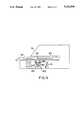
- FIG. 1is a plan view of one embodiment of a capillary mixing cartridge useful in the practice of the present invention.
- FIG. 2is a cross-sectional view taken along line A--A of the embodiment shown in FIG. 1.
- FIG. 3provides a series of three views of a system of the invention using a mixing cartridge of the embodiment of FIG. 1 and a monitor, in which panels A and B show instantaneous views during the mixing operation, and panel C shows particles drawn into a sub-region of the chamber by a linear magnetic field after mixing.
- FIG. 4is a cross-sectional view of one embodiment of the system.
- the present inventionprovides a method and device for carrying out mechanical mixing of liquids in capillary spaces.
- the mixingcan be carried out using a plurality of magnetic or magnetically inducible particles and a moving magnetic field.
- the particlesform temporary aggregates that act like larger mixing bars; when subjected to a rotating magnetic field, the particles often forming a number of small bar-like aggregates that rotate in phase.
- the bar-like aggregatesform, break up upon contact with resistance, and reform to provide an unexpectedly flexible and efficient mixing system for capillary spaces.
- a capillary spaceis considered here to be a chamber of some physical device in which two surfaces are spaced apart at a distance which allows capillary flow through the space. Only one of the three orthogonal dimensions necessarily has this capillary spacing, with the remaining dimensions typically being greater than capillary spacing (a chamber with two orthogonal capillary dimensions would be a capillary tube).
- the most typical example of a capillary spaceis formed by two flat plates spaced apart by an appropriate distance, with side walls serving to confine the liquid and to act as spacers between the two surfaces.
- the spacecan deviate from simple planar form and can undulate significantly, even so that lower surfaces are found at elevations above nearby upper surfaces, if desired.
- Such chamber shapeswhile suitable for the present invention, would not allow ordinary mixing with a stirring bar or similar microscopic mixer.
- Typical capillary dimensions for aqueous liquidsare from 0.01 to 2.0 mm, preferably 0.05 to 1.0 mm, with typical non-capillary dimensions being larger than 2 mm.
- the width of the chamber and its lengthhave no maximum, but they are typically small since the goal of such an apparatus is normally to mix small volumes of liquid. Widths are therefore generally less than 30 mm, often less than 20 mm, and the lengths of the mixing chamber are of similar dimensions (but not necessarily equal dimensions; i.e., oval and rectangular shapes are permitted and even preferred for some embodiments).
- a passageway leading into or out of the chambercan be of any convenient dimensions, as described in more detail below.
- capillary passagewaysare provided in order to allow access of liquids into and out of the apparatus and to provide for additional handling of liquids in the apparatus at locations other than the mixing chamber while still resorting solely to capillary force and gravity to provide fluid flow.
- Such passagewaysare not considered to be part of the chamber, although they will generally form a capillary pathway in combination with the chamber.
- the particlescan be added to the chamber as a suspension in one of the liquids to be mixed or can be present in the chamber when a liquid in introduced.
- the particlesare present together with a reagent composition that will react with some component in the liquid or liquids to be mixed.
- the reagent compositionis one that will dissolve or be suspended in the mixture that is being formed in the mixing chamber.
- the particleshave a maximum length that is a small fraction of the length or width of the chamber in which mixing takes place. Typically, the particles have a maximum length of less than 0.2 mm and will of necessity have at least one dimension smaller than the capillary spacing of the chamber. No minimum length or preferred shape of particles appears to exist. Particles smaller than a single magnetic domain will work in a mixer of the invention. Examples of typical mixing particles include magnetite, barium ferrite, and so-called "Magic® particles," which are iron oxide particles covered with a polymeric coat. Other exemplary particles include iron and steel filings.
- magnetizable particlesare available commercially for other purposes and can simply be purchased and used for purposes of the invention instead of for their originally intended purpose.
- the Magic® reagent systemis an assay system that uses such particles to act as support surfaces in immunoassays, with the magnetic properties being used in a step that separates the particles from the liquid portion of the assay mixture. Nevertheless, they can be used to provide mixing as described herein.
- Other material, such as iron filings, magnetite, and barium ferrite,are available from numerous scientific supply houses, where they have previously been supplied to, among other purposes, visually demonstrate the presence of magnetic fields.
- particleswork best when they are not permanently magnetic but are magnetically inducible under the influence of a magnetic field gradient. This property obviates the difficulties of undesirable clumping of particles when they are stored or dispensed.
- Preferred particlesare paramagnetic, defined as a material with magnetic susceptibility >0 and relative permeability >1. The particles are preferably smaller than the critical size necessary for the particle to be permanently magnetic (which varies with the properties of the particular inducible composition).
- the volume of magnetic particles used in the mixing chamberwill vary with the desired rate of mixing, viscosity of the fluid, and volume of the chamber.
- a typical volume occupied by the magnetic particlesis from 0.1 to 20% of the volume of the chamber, preferably from 0.5 to 10% of the chamber volume, and more preferably from 1 to 4%.
- the particlespreferably have a density more than that of the liquid in the mixing chamber. Since most solutions are aqueous and have a density of approximately 1 g/ml, particles with a density of 2 g/ml are preferred, more preferably at least 4 g/ml. Since the particles are or contain metal, such densities are easily realized. Even particles coated with plastic (polymeric) materials having a specific density of less than 1 will have an overall density in the indicated size range if the coating is selected to be of appropriate thickness to provide the indicated density.
- reagent additivescan be included to adapt the reagent properties to the desired application.
- whole bloodis to be mixed with a reagent during its transit through the capillary chamber for an assay in which lysis of the red cells in not desired, several qualities are desirable for the formulation:
- the formulationshould not hemolyze blood cells during either the dissolution or the mixing of the reagent.
- the dry formulationshould be readily dissolvable so as to allow dissolution to take place.
- the formulationshould preferably not result in significantly increasing the osmotic pressure of the plasma, which would cause red cell shrinkage and consequent dilution of plasma components to be measured.
- the additivesshould preferably not cause interference of the chemistries to be performed.
- bovine serum albuminwhen added to a reagent composition has been shown to slow flow and enhance re-suspension.
- Polyethylene glycol and sucrosehave been shown to prevent hemolysis and enhance wetability.
- each mixing applicationcan be optimized for its specific needs, and that the preferred characteristics of the formulations will change from analysis to analysis. For example, when hemoglobin is being measured, hemolysis is a desirable trait, in opposition to the example above. In any event, the preparation of a particular reagent formulation will not modify the present invention, which is directed to the mixing operation itself.
- FIG. 1is a plan view of a typical device, showing a liquid-impervious housing 10 in which all of the interior chambers of the device are formed.
- central chamber 20 in housing 10contains a plurality of magnetic particles 25.
- Two capillary passagewaysare present in the device, an entrance passageway 30 and an exit passageway 40. Entrance (50) and exit (60) holes in the surface of housing 10 are provided in order to allow entrance of liquids and exit of gases, such as air that would otherwise be trapped and prevent capillary flow.
- FIG. 2The formation of interior spaces is apparent in FIG. 2, in which the same reference numerals are utilized in a cross-sectional view of the same embodiment as FIG. 1, taken along line A--A of FIG. 1.
- the vertical height of each interior chamberis seen to be of capillary dimensions in order to provide capillary flow throughout the interior of the device. Entrance and exit passageways 50 and 60 are apparent in the top surface of housing 10.
- FIG. 4shows a system of the invention, including a means for generating a moving magnetic field (magnets 80 attached to a rotating shaft 90 of an electric motor 100) mounted in an instrument 70 into which the chamber device 10 is inserted.
- An optical detection device 110is shown oriented to interrogate the chamber device at the post-chamber passageway.
- collectionis provided by idsplacement of the mixing device as indicated by the arrow 120.
- the insertion of the chamber device into the slot in the instrumentprovides a means for retaining the chamber device in proper orientation.
- FIG. 3shows a mixing operation.
- the particlesare present before mixing takes place, they are typically distributed randomly throughout chamber 20, as shown in FIG. 1.
- the particlescan be introduced along with one of the components to be mixed.
- the particlesalign with the magnetic field vector.
- Panels A and B of FIG. 3shows instantaneous views of the middle of a mixing operation using a rotating magnetic field in which the aggregate clusters are formed into linear aggregates, as shown at 25'.
- Each of the aggregatesrotates about its own central axis in the presence of the rotating magnetic field, and the aggregates are free to break up and reform during the mixing operation, as can be seen by comparing the number and size of the aggregates in Panels A and B (fewer but larger cluster are present in Panel B, as tends to occur over time with mixing). Additionally, the aggregates precess around the mixing chamber so that their centers of rotation move with time. The rotating aggregates thus "walk” around the chamber as they rotate, sweeping out all areas of the chamber and ensuring complete mixing.
- the presence of irregularities in the mixing chamber or in the liquid or reagent to be mixeddo not prevent proper mixing, since the aggregates merely break up and reform upon encountering resistance at any particular location, while persisting in their rotation at the edges of the irregularities until a homogeneous mixture is obtained.
- the aggregates that formare not necessarily linear. Other shapes, such as curves and spirals, also occur. The shape of the aggregates appears to be determined by the rotation rate and the viscosity of the liquid being mixed.
- Panel Cshows a useful feature of the aggregates, since they break up and the individual particles can be collected when the rotating magnetic field ceases and a linear-gradient magnetic field is applied to the particles.
- the particlescan be collected at a single location in the mixing chamber. This property could be used, for example, to collect the magnetic particles so that mixed liquid can traverse an exit capillary passageway to another location in housing 10 without carrying particles into that location. Other useful aspects of mass movement of the collected particles are discussed below.
- This systemtypically comprises a single-use, disposable, analytical cartridge, most often made by welding together two or more plastic pieces (usually prepared by injection molding) containing various channels and chambers; sample movement is typically but not necessarily provided by capillary force.
- the cartridgecan contain multiple chambers capable of mixing sample in multiple capillary tracks, multiple chambers in a single track, or only a single chamber in a single capillary track.
- the capillary trackscomprise (in addition to the mixing chamber) an entry port for entry of sample into the track, a capillary section that provides for sample flow and containment, and a vent to allow trapped air to escape so that capillary flow can take place.
- multiple capillary tracksuse a common sample entry port; in other cases, entirely separate tracks with separate entry ports are provided.
- the capillary sectionsare generally divided into several subsections that provide for different functions, such as sample flow, dissolution of reagent, analysis of results, verification of proper operation, or venting of air.
- the geometry of these sectionsvary with their purpose. For example, dissolution and/or mixing of reagents normally takes place in broad capillary chambers that provide a large surface area to which reagents can be applied and from which they will be rapidly re-suspended or dissolved upon contact by sample.
- at least one, but not necessarily all, mixing chamberswill contain magnetic particles and be used as described herein.
- Sample flowis normally regulated by the dimensions of the capillary channels and the physical properties of the sample intended for use in a given cartridge.
- Liquids entering the cartridgecan be modified in the capillary tracks or in an entry port prior to entry of sample into the capillary track to provide a sample better suited to a particular analysis.
- bloodcan be filtered to provide plasma or lysed to provide a uniform, lysed medium. Filtration of red blood cells in capillary tracks is described in U.S. Pat. No. 4,753,776.
- the samplecan also be lysed by passage through a porous disc, which contains an agent that lyses red cells (discussed in detail below). The "lysate" can then be distributed into one or more capillary tracks for the individual assays.
- the assay systemalso comprises a monitor (analytical instrument) capable of reading at least one and usually more assays simultaneously.
- the monitorwill therefore comprise detection systems and can also include verification systems (each of which can be a detection system utilized with different software or hardware in the detector or can be a separate system at various locations in the monitor) to detect any failure of the system.
- Monitors for performing single analysesare described in U.S. Pat. No. 4,756,884 and in U.S. application Ser. Nos. 016,506, filed Feb. 17, 1987, and 341,079, filed Apr. 20, 1989. Also, see U.S. Pat. No. 4,829,011 for a detector system that can be used in a monitor to detect agglutination of particles in a capillary track.
- monitorscan be readily adapted to use in the present invention simply by including a magnetic field generator, which can be a simple mechanically permanent magnet or an electromagnet generated mechanically or electronically. Motion is usually provided by moving the magnetic, but a moving electromagnetic field can be generated electromechanically (as in an electric motor) or entirely by electric or electronic switching of multiple electromagnetic elements.
- a magnetic field generatorwhich can be a simple mechanically permanent magnet or an electromagnet generated mechanically or electronically. Motion is usually provided by moving the magnetic, but a moving electromagnetic field can be generated electromechanically (as in an electric motor) or entirely by electric or electronic switching of multiple electromagnetic elements.
- the monitorWhen used to detect the presence, absence, or amount of a particular analyte in a mixed sample, the monitor is provided with appropriate analysis and verification systems. For a number of systems that can be used to determine whether analysis has occurred correctly in a cartridge inserted into an instrument (and therefore not visible to the user), see U.S. application Ser. No. 337,286, filed Apr. 13, 1989.
- Stop-flow junctionrefers to a control region in a capillary passageway that has been used in a number of prior inventions arising out of the laboratories of the inventors and in other laboratories (see, for example, U.S. Pat. Nos. 3,799,742 and 4,946,795 and U.S. application Ser. No. 07/663,217, filed Mar. 1, 1991).
- a stop-flow junctionis a region in a fluid track that marks the junction between an early part of the track in which sample flows by capillary action (and optionally gravity) and a later part of the fluid track into which sample does not normally flow until flow is initiated by some outside force, such as an action of the user.
- the stop-flow junctioncan be used to halt flow while the mixing operation takes place. When sufficient mixing has occurred, flow will be initiated so that other operations, such as measurement operations, can take place at locations further along the internal capillary passageway of the device.
- a number of stop-flow junctionsare described in U.S. Pat. Nos. 4,868,129 and 5,077,017 and in application Ser. Nos. 07/337,286, filed Apr. 13, 1989, and 07/663,217, filed Mar. 1, 1991.
- the mixingcan take place in the last chamber of a capillary passageway. If there is a need to optically examine the sample in the absence of the magnetic particles, the particles can be drawn to one side of the chamber after mixing using a linear motion imparted by a magnetic field.
- capillary flow through the devicecan be slowed rather than stopped by proper sizing of various capillary passageways by providing flow barriers as described in the previously cited patents and patent applications (especially U.S. Pat. Nos. 4,233,029 and 4,618,476).
- changes in the surface energy characteristics of the capillary passageway surfacescan be used to slow flow. For example, making the surface more hydrophobic will reduce the flow rate when the sample is aqueous.
- a linear magnetic field gradientcan be used for purposes other than simple displacement of magnet particles.
- the generation or motion of a magnetic field gradient and the resulting motion of the magnetic particlescan be used, by selecting the proper orientation, to provide a starting impulse that overcomes a stop-flow barrier and allows capillary flow to continue to other portions of the apparatus.
- the particleswill typically be collected near the entrance passageway to the mixing chamber and then moved rapidly in the direction of the exit passageway that contains the stop-flow junction. The pressure imparted to the fluid will re-initiate capillary flow, and the particles will be stopped before they reach the exit to the mixing chamber, thus preventing the particles from being passed further along the passageway.
- the necessary magnetic field for operation of the apparatuscan be generated in any of the manners currently being used to generate magnetic fields (see above).
- the magnetic fieldshould ideally extend over the entire mixing chamber, but the magnetic field has no particular limitations other than being of sufficient strength and gradient to move the particles.
- Magnetic field strengths that result in successful operationcan readily be determined empirically and are generally of the order provided by permanent magnets located 0.01 to 10 cm, preferably 0.3 to 4 cm, from the particles. There does not appear to be a limit on the low end of the movement rate other than to prove the desired rate of mixing. Even very slow movement will eventually result in complete mixing.
- Preferred rates of rotation of a rotating magnetic fieldthat will ensure mixing within a time useful for most diagnostic systems are from 10 to 5,000 rotations per minute (rpm), more preferably 400 to 3,000 rpm, and most preferably about 1,000 rpm.
- rpmrotations per minute
- a rotating magnetic fieldpasses through the geometric center of the chamber in which mixing has taken place. Satisfactory mixing can occur even when the axis of the rotating magnetic field does not pass through the mixing chamber at all.
- the axis of the rotating magnetic fielddoes pass through the mixing chamber.
- Rotating permanent magnets, electromagnets, or electronically generated rotating magnetic fieldscan be used to provide the desired rotating motion.
- a permanent magnetcan be displaced linearly in either a regular, or random pattern by a mechanical operation.
- an electromagnet generated at a series of adjacent locations near the mixing chambercan be used for linear movement of the particles.
- a typical mixing system of the inventioncomprises at least the chamber device with its various capillary passageways, chambers, and magnetic particles and a magnetic device containing the apparatus that generates the rotating magnetic field.
- the two componentsare designed so that the chamber device is retained in the magnetic device with the magnetic field and any analytical detectors oriented properly with respect to the chamber.
- the shape of the chamber device or magnetic deviceas a whole, and the proper design of the magnetic field generator is a relatively minor design function in the design of the overall chamber device and monitor.
- a circular reagent mixing chamber 0.012" deep and 0.28" diameterwas milled into 0.06" thick ABS plastic.
- Two small permanent magnetswere mounted on the shaft of a small electric motor.
- the magnetswere 0.2 ⁇ 0.2 ⁇ 0.25 inches, magnetized parallel to the long axis and made from Neodymium/Iron/Boron with peak energy 35 MGauss-Oersted. They were mounted symmetrically 0.6 inches apart (center-center) with their magnetic axis parallel to the axis of rotation and their poles directed in opposite senses. This device was set up 0.06 inches below the cartridge with the axis of rotation directed to the middle of the mixing chamber. The rotation rate was 1200 rpm. In mixing experiments, cartridges were placed on a flat stage registered to the mixer.
- Table 1describes the properties of the materials evaluated and results of tests according to the above criteria. As seen in table 1, magnetite satisfied all the preliminary selection criteria, being capable of more powerful mixing action than the Magic® particles and less hemolytic than Barium ferrite. Mixing efficiency was related to the content of the magnetic material of the particles, as only a fraction of the Magic® particles (specific density 2.5) is iron oxide, the rest being a polymer coating that is not magnetically active. In contrast, magnetite has a specific density of 5.2 and barium ferrite, 5.4.
- a capillary cartridge with a hole for applying blood sampleswas prepared with a 0.012" deep chamber 0.28" in diameter reached by a capillary track 0.012" deep and 0.06" wide.
- a suspension of magnetite particles(Johnson Matthey Electronics #12374) was prepared in a reagent comprising components for precipitating LDL-cholesterol from plasma:
- the final concentration of magnetite particleswas 2.7 vol % .
- Four microliters of this suspensionwere spread and dried onto the upper surface of the chamber.
Landscapes
- Chemical & Material Sciences (AREA)
- Chemical Kinetics & Catalysis (AREA)
- Automatic Analysis And Handling Materials Therefor (AREA)
- Mixers With Rotating Receptacles And Mixers With Vibration Mechanisms (AREA)
- Investigating Or Analysing Biological Materials (AREA)
- Processing And Handling Of Plastics And Other Materials For Molding In General (AREA)
- Sampling And Sample Adjustment (AREA)
Abstract
Description
TABLE 1 __________________________________________________________________________Properties of magnetic materials Particle Size Magnetic Relative Mixing Lysis.sup.2 Material Physical Form (micron) Susceptibility Permeability Efficiency.sup.1 (mg/dL) __________________________________________________________________________Magic ® Particles brown slurry 1-4 99 100 poor <100 Magnetite black powder <3 99 100 very good <100 Barium Ferrite black powder 2.5-4 excellent >500 __________________________________________________________________________ .sup.1 Visual inspection of particle and bulk flow movement. .sup.2 Whole blood samples mixed with suspensions of the particles are spun and the plasma visually inspected.
TABLE 1 ______________________________________ Absorbance (580 nm - 520 nm) × 1000 Section # Before Mix After Mix ______________________________________ 1 29 158 2 140 156 3 183 156 4 221 155 5 244 155 6 251 157 ______________________________________
TABLE 2 ______________________________________ Measured HDL-Cholesterol Total Cholesterol Reflectance Sam- (actual (actual Cholesterol ple concentration concentration Signal (K/S) No. mg/dL) mg/dL) (average of 5 tests) ______________________________________ 1 47.3 210 0.750 2 56.1 152 0.958 3 60.5 182 1.017 4 66.0 213 1.189 5 67.1 165 1.261 6 96.0* 96 2.38 ______________________________________
TABLE 3 ______________________________________ Sample HDL-Cholesterol Measured Reflectance No. (actual mg/dL) Signal (K/S) ______________________________________ 1 0.787 44 2 0.834 51 3 1.304 67 ______________________________________
Claims (21)
Priority Applications (7)
| Application Number | Priority Date | Filing Date | Title |
|---|---|---|---|
| US07/867,155US5222808A (en) | 1992-04-10 | 1992-04-10 | Capillary mixing device |
| PCT/US1993/003248WO1993020932A1 (en) | 1992-04-10 | 1993-04-07 | Capillary mixing device |
| AU39751/93AAU3975193A (en) | 1992-04-10 | 1993-04-07 | Capillary mixing device |
| JP5518442AJP2801403B2 (en) | 1992-04-10 | 1993-04-07 | Capillary mixing device |
| EP9393909274AEP0591505A4 (en) | 1992-04-10 | 1993-04-07 | Capillary mixing device |
| CA002109703ACA2109703C (en) | 1992-04-10 | 1993-04-07 | Capillary mixing device |
| JP10068400AJP3135057B2 (en) | 1992-04-10 | 1998-03-18 | Capillary mixing device |
Applications Claiming Priority (1)
| Application Number | Priority Date | Filing Date | Title |
|---|---|---|---|
| US07/867,155US5222808A (en) | 1992-04-10 | 1992-04-10 | Capillary mixing device |
Publications (1)
| Publication Number | Publication Date |
|---|---|
| US5222808Atrue US5222808A (en) | 1993-06-29 |
Family
ID=25349230
Family Applications (1)
| Application Number | Title | Priority Date | Filing Date |
|---|---|---|---|
| US07/867,155Expired - LifetimeUS5222808A (en) | 1992-04-10 | 1992-04-10 | Capillary mixing device |
Country Status (6)
| Country | Link |
|---|---|
| US (1) | US5222808A (en) |
| EP (1) | EP0591505A4 (en) |
| JP (2) | JP2801403B2 (en) |
| AU (1) | AU3975193A (en) |
| CA (1) | CA2109703C (en) |
| WO (1) | WO1993020932A1 (en) |
Cited By (67)
| Publication number | Priority date | Publication date | Assignee | Title |
|---|---|---|---|---|
| US5478751A (en)* | 1993-12-29 | 1995-12-26 | Abbott Laboratories | Self-venting immunodiagnositic devices and methods of performing assays |
| FR2789331A1 (en)* | 1999-02-08 | 2000-08-11 | Gerard Bienvenu | PROCESS AND DEVICE FOR ACTIVATION OF A PHYSICAL AND / OR CHEMICAL REACTION IN A FLUID MEDIUM |
| US6190034B1 (en)* | 1995-10-03 | 2001-02-20 | Danfoss A/S | Micro-mixer and mixing method |
| WO2001043871A3 (en)* | 1999-12-06 | 2002-01-03 | Incyte Genomics Inc | Microarray hybridization chamber |
| US20020150933A1 (en)* | 1999-07-02 | 2002-10-17 | Ralf Ehricht | Microchip matrix device for duplicating and characterizing nucleic acids |
| US20020174878A1 (en)* | 1998-08-21 | 2002-11-28 | Life Technologies, Inc. | Apparatus for washing magnetic particles |
| US20020187560A1 (en)* | 2001-06-07 | 2002-12-12 | Nanostream, Inc. | Microfluidic systems and methods for combining discrete fluid volumes |
| US20030013115A1 (en)* | 1997-06-16 | 2003-01-16 | Diversa Corporation, A Delaware Corporation | Capillary array-based sample screening |
| US6513968B2 (en) | 1998-08-21 | 2003-02-04 | Agilent Technologies, Inc. | Apparatus and method for mixing a film of fluid |
| US20030064507A1 (en)* | 2001-07-26 | 2003-04-03 | Sean Gallagher | System and methods for mixing within a microfluidic device |
| US20030124509A1 (en)* | 1999-06-03 | 2003-07-03 | Kenis Paul J.A. | Laminar flow patterning and articles made thereby |
| EP1327473A1 (en)* | 2001-12-18 | 2003-07-16 | Riken | Method of stirring reaction solutions |
| US20030133358A1 (en)* | 2002-01-11 | 2003-07-17 | Nanostream, Inc. | Multi-stream microfluidic aperture mixers |
| US20030198130A1 (en)* | 2000-08-07 | 2003-10-23 | Nanostream, Inc. | Fluidic mixer in microfluidic system |
| US20030198576A1 (en)* | 2002-02-22 | 2003-10-23 | Nanostream, Inc. | Ratiometric dilution devices and methods |
| US6653089B2 (en) | 2000-09-18 | 2003-11-25 | President And Fellows Of Harvard College | Differential treatment of selected parts of a single cell with different fluid components |
| US20040013584A1 (en)* | 2002-05-27 | 2004-01-22 | Frank Arndt | Reactor for the treatment of a sample medium |
| US20040022123A1 (en)* | 2002-07-03 | 2004-02-05 | Bio/Data Corporation | Method and apparatus for using vertical magnetic stirring to produce turbulent and chaotic mixing in various states, without compromising components |
| US6739576B2 (en) | 2001-12-20 | 2004-05-25 | Nanostream, Inc. | Microfluidic flow control device with floating element |
| US20040121449A1 (en)* | 2002-12-19 | 2004-06-24 | Pugia Michael J. | Method and apparatus for separation of particles in a microfluidic device |
| US20040190372A1 (en)* | 2003-03-28 | 2004-09-30 | Hyclone Laboratories, Inc. | Container systems for mixing fluids with a magnetic stir bar |
| US20040241042A1 (en)* | 2003-05-29 | 2004-12-02 | Pugia Michael J. | Packaging of microfluidic devices |
| US20040241659A1 (en)* | 2003-05-30 | 2004-12-02 | Applera Corporation | Apparatus and method for hybridization and SPR detection |
| US20040265171A1 (en)* | 2003-06-27 | 2004-12-30 | Pugia Michael J. | Method for uniform application of fluid into a reactive reagent area |
| US20040265172A1 (en)* | 2003-06-27 | 2004-12-30 | Pugia Michael J. | Method and apparatus for entry and storage of specimens into a microfluidic device |
| US20050002274A1 (en)* | 2001-10-03 | 2005-01-06 | Terentiev Alexandre N. | Mixing bag or vessel having a receiver for a fluid-agitating element |
| US6852547B2 (en)* | 2002-08-01 | 2005-02-08 | Arizona Board Of Regents | Dynamically formed rotors for lock-in amplifier detection |
| US20050041525A1 (en)* | 2003-08-19 | 2005-02-24 | Pugia Michael J. | Mixing in microfluidic devices |
| US6890093B2 (en) | 2000-08-07 | 2005-05-10 | Nanostream, Inc. | Multi-stream microfludic mixers |
| US20050117449A1 (en)* | 2001-04-10 | 2005-06-02 | Terentiev Alexandre N. | Sterile fluid pumping or mixing system and related method |
| US6908593B1 (en)* | 2000-03-31 | 2005-06-21 | Lifescan, Inc. | Capillary flow control in a fluidic diagnostic device |
| US6911343B2 (en) | 1999-06-30 | 2005-06-28 | Agilent Technologies, Inc. | Method for conducting chemical or biochemical reactions on a solid surface within an enclosed chamber |
| US20050202504A1 (en)* | 1995-06-29 | 2005-09-15 | Affymetrix, Inc. | Miniaturized genetic analysis systems and methods |
| US20050220668A1 (en)* | 2004-04-06 | 2005-10-06 | Bio/Data Corporation | Disposable test device with sample volume measurement and mixing methods |
| US20060081539A1 (en)* | 2002-04-26 | 2006-04-20 | Abbott Laboratories | Structure and method for handling magnetic particles in biological assays |
| US20060092761A1 (en)* | 2000-10-09 | 2006-05-04 | Terentiev Alexandre N | Mixing vessel with a fluid-agitating element supported by a roller bearing |
| US20060144448A1 (en)* | 2002-09-02 | 2006-07-06 | Goody Brian A | Production of variable concentration fluid mixtures |
| US7125711B2 (en) | 2002-12-19 | 2006-10-24 | Bayer Healthcare Llc | Method and apparatus for splitting of specimens into multiple channels of a microfluidic device |
| US20070207272A1 (en)* | 2006-03-03 | 2007-09-06 | Puri Ishwar K | Method and apparatus for magnetic mixing in micron size droplets |
| WO2007118261A1 (en)* | 2006-04-13 | 2007-10-25 | Austrian Research Centers Gmbh - Arc | Apparatus for enhancing the reaction efficiency, especially the binding efficiency, between molecules and molecular moieties |
| US20080035579A1 (en)* | 2006-08-11 | 2008-02-14 | Samsung Electronics Co., Ltd. | Centrifugal magnetic position control device, disk-shaped micro fluidic system including the same, and method of operating the compact disk-shaped micro fluidic system |
| WO2007141691A3 (en)* | 2006-06-02 | 2008-02-14 | Koninkl Philips Electronics Nv | Microelectronic sensor device with washing means |
| US20080101991A1 (en)* | 2005-06-23 | 2008-05-01 | Arkray, Inc. | Analysis Tool |
| EP1944078A1 (en) | 2007-01-10 | 2008-07-16 | F.Hoffmann-La Roche Ag | Device for determining an analyte in a liquid, stirring device and method |
| US20080236303A1 (en)* | 2007-03-30 | 2008-10-02 | Fujifilm Corporation | Sample detecting method and instrument |
| US20080257754A1 (en)* | 2003-06-27 | 2008-10-23 | Pugia Michael J | Method and apparatus for entry of specimens into a microfluidic device |
| US20090027998A1 (en)* | 2007-07-25 | 2009-01-29 | Abbott Laboratories | Magnetic mixer |
| US20100157725A1 (en)* | 2007-02-21 | 2010-06-24 | Terentiev Alexandre N | Roller Bearing for a Fluid-Agitating Element and Associated Vessel |
| US20100233822A1 (en)* | 2006-01-25 | 2010-09-16 | Koninklijke Philips Electronics N.V. | Device for analyzing fluids |
| US20100252507A1 (en)* | 2006-01-26 | 2010-10-07 | Frederic Lacharme | Magnetic Bead Retention Apparatus and Method |
| US20100311186A1 (en)* | 2006-07-28 | 2010-12-09 | Biosite Incorporated | Devices and methods for performing receptor binding assays using magnetic particles |
| US20110019497A1 (en)* | 2008-03-28 | 2011-01-27 | Arkray, Inc. | Fluid agitation method, fluid agitation system, and cartridge |
| US8034245B1 (en) | 2006-12-19 | 2011-10-11 | The United States Of America As Represented By The United States Department Of Energy | Method of driving liquid flow at or near the free surface using magnetic microparticles |
| EP2038900A4 (en)* | 2006-06-21 | 2012-12-12 | Spinomix Sa | A method for manipulating magnetic particles in a liquid medium |
| US8857244B2 (en) | 2008-12-23 | 2014-10-14 | C A Casyso Ag | Cartridge device for a measuring system for measuring viscoelastic characteristics of a sample liquid, a corresponding measuring system, and a corresponding method |
| WO2015017413A1 (en)* | 2013-07-29 | 2015-02-05 | Mbio Diagnostics, Inc. | Assay cartridge processing systems and methods and associated assay cartridges |
| WO2016020747A3 (en)* | 2014-08-06 | 2016-04-21 | Preciflex Sa | Time-keeping devices including indications by magnetic particles in suspension in liquid filled chambers |
| CN105628948A (en)* | 2016-03-04 | 2016-06-01 | 深圳普门科技有限公司 | High-speed C reactive protein analyzer and analyzing method thereof |
| USD777343S1 (en) | 2015-05-28 | 2017-01-24 | C A Casyso Ag | Body fluid cartridge device |
| US9897618B2 (en) | 2014-09-29 | 2018-02-20 | C A Casyso Gmbh | Blood testing system |
| US10175225B2 (en) | 2014-09-29 | 2019-01-08 | C A Casyso Ag | Blood testing system and method |
| US10288630B2 (en) | 2014-09-29 | 2019-05-14 | C A Casyso Gmbh | Blood testing system and method |
| US10295554B2 (en) | 2015-06-29 | 2019-05-21 | C A Casyso Gmbh | Blood testing system and method |
| US10473674B2 (en) | 2016-08-31 | 2019-11-12 | C A Casyso Gmbh | Controlled blood delivery to mixing chamber of a blood testing cartridge |
| US10539579B2 (en) | 2014-09-29 | 2020-01-21 | C A Casyso Gmbh | Blood testing system and method |
| US10816559B2 (en) | 2014-09-29 | 2020-10-27 | Ca Casyso Ag | Blood testing system and method |
| US10843185B2 (en) | 2017-07-12 | 2020-11-24 | Ca Casyso Gmbh | Autoplatelet cartridge device |
Families Citing this family (4)
| Publication number | Priority date | Publication date | Assignee | Title |
|---|---|---|---|---|
| US6571651B1 (en) | 2000-03-27 | 2003-06-03 | Lifescan, Inc. | Method of preventing short sampling of a capillary or wicking fill device |
| FR2841158B1 (en)* | 2002-06-24 | 2007-02-23 | Bio Merieux | THERMO-PNEUMATICALLY FLEXIBLE FLUID DEVICE ISOLATION AND POSSIBLY AGITATION OF THE CONTENT OF AN OPERATIVE CAVITY |
| KR100485317B1 (en)* | 2002-10-25 | 2005-04-27 | 전자부품연구원 | Micro mixer and method of manufacturing the same |
| GB201711804D0 (en)* | 2017-07-21 | 2017-09-06 | Mast Group Ltd | Apparatus for conducting an assay |
Citations (11)
| Publication number | Priority date | Publication date | Assignee | Title |
|---|---|---|---|---|
| US3799742A (en)* | 1971-12-20 | 1974-03-26 | C Coleman | Miniaturized integrated analytical test container |
| US4054270A (en)* | 1974-06-20 | 1977-10-18 | The United States Of America As Represented By The Secretary Of Agriculture | Micro mixing apparatus and method |
| US4233029A (en)* | 1978-10-25 | 1980-11-11 | Eastman Kodak Company | Liquid transport device and method |
| US4426451A (en)* | 1981-01-28 | 1984-01-17 | Eastman Kodak Company | Multi-zoned reaction vessel having pressure-actuatable control means between zones |
| US4618476A (en)* | 1984-02-10 | 1986-10-21 | Eastman Kodak Company | Capillary transport device having speed and meniscus control means |
| US4728500A (en)* | 1985-08-07 | 1988-03-01 | Toyo Soda Manufacturing Co., Ltd. | Stirrer for biochemical reactions |
| US4756884A (en)* | 1985-08-05 | 1988-07-12 | Biotrack, Inc. | Capillary flow device |
| US4876069A (en)* | 1981-07-11 | 1989-10-24 | Siegfried Jochimsen | Blood clotting time measuring apparatus |
| US4946795A (en)* | 1987-08-27 | 1990-08-07 | Biotrack, Inc. | Apparatus and method for dilution and mixing of liquid samples |
| US5028142A (en)* | 1989-04-06 | 1991-07-02 | Biotrack, Inc. | Reciprocal mixer |
| US5077017A (en)* | 1987-11-05 | 1991-12-31 | Biotrack, Inc. | Integrated serial dilution and mixing cartridge |
Family Cites Families (6)
| Publication number | Priority date | Publication date | Assignee | Title |
|---|---|---|---|---|
| GB1256429A (en)* | 1969-05-15 | 1971-12-08 | Sp Kb Magnitnoi Gidrodinamiki | Apparatus for mixing electrically conductive liquids with reagents |
| GB1523637A (en)* | 1975-12-11 | 1978-09-06 | Ambrosimov V A | Working of materials |
| SU882579A1 (en)* | 1978-05-18 | 1981-11-23 | Северо-Западный Заочный Политехнический Институт | Continuous-action mixer |
| JPS5711414A (en)* | 1980-06-25 | 1982-01-21 | Fujikura Ltd | Refractory insulated wire |
| US4522501A (en)* | 1984-04-06 | 1985-06-11 | Northern Telecom Limited | Monitoring magnetically permeable particles in admixture with a fluid carrier |
| SE8601528D0 (en)* | 1986-04-07 | 1986-04-07 | Leo Ab | MIXING APPARATUS AND METHOD |
- 1992
- 1992-04-10USUS07/867,155patent/US5222808A/ennot_activeExpired - Lifetime
- 1993
- 1993-04-07EPEP9393909274Apatent/EP0591505A4/ennot_activeCeased
- 1993-04-07WOPCT/US1993/003248patent/WO1993020932A1/ennot_activeApplication Discontinuation
- 1993-04-07JPJP5518442Apatent/JP2801403B2/ennot_activeExpired - Fee Related
- 1993-04-07AUAU39751/93Apatent/AU3975193A/ennot_activeAbandoned
- 1993-04-07CACA002109703Apatent/CA2109703C/ennot_activeExpired - Fee Related
- 1998
- 1998-03-18JPJP10068400Apatent/JP3135057B2/ennot_activeExpired - Fee Related
Patent Citations (11)
| Publication number | Priority date | Publication date | Assignee | Title |
|---|---|---|---|---|
| US3799742A (en)* | 1971-12-20 | 1974-03-26 | C Coleman | Miniaturized integrated analytical test container |
| US4054270A (en)* | 1974-06-20 | 1977-10-18 | The United States Of America As Represented By The Secretary Of Agriculture | Micro mixing apparatus and method |
| US4233029A (en)* | 1978-10-25 | 1980-11-11 | Eastman Kodak Company | Liquid transport device and method |
| US4426451A (en)* | 1981-01-28 | 1984-01-17 | Eastman Kodak Company | Multi-zoned reaction vessel having pressure-actuatable control means between zones |
| US4876069A (en)* | 1981-07-11 | 1989-10-24 | Siegfried Jochimsen | Blood clotting time measuring apparatus |
| US4618476A (en)* | 1984-02-10 | 1986-10-21 | Eastman Kodak Company | Capillary transport device having speed and meniscus control means |
| US4756884A (en)* | 1985-08-05 | 1988-07-12 | Biotrack, Inc. | Capillary flow device |
| US4728500A (en)* | 1985-08-07 | 1988-03-01 | Toyo Soda Manufacturing Co., Ltd. | Stirrer for biochemical reactions |
| US4946795A (en)* | 1987-08-27 | 1990-08-07 | Biotrack, Inc. | Apparatus and method for dilution and mixing of liquid samples |
| US5077017A (en)* | 1987-11-05 | 1991-12-31 | Biotrack, Inc. | Integrated serial dilution and mixing cartridge |
| US5028142A (en)* | 1989-04-06 | 1991-07-02 | Biotrack, Inc. | Reciprocal mixer |
Cited By (140)
| Publication number | Priority date | Publication date | Assignee | Title |
|---|---|---|---|---|
| US5478751A (en)* | 1993-12-29 | 1995-12-26 | Abbott Laboratories | Self-venting immunodiagnositic devices and methods of performing assays |
| US20050202504A1 (en)* | 1995-06-29 | 2005-09-15 | Affymetrix, Inc. | Miniaturized genetic analysis systems and methods |
| US6190034B1 (en)* | 1995-10-03 | 2001-02-20 | Danfoss A/S | Micro-mixer and mixing method |
| US20030013115A1 (en)* | 1997-06-16 | 2003-01-16 | Diversa Corporation, A Delaware Corporation | Capillary array-based sample screening |
| US20080279037A1 (en)* | 1998-08-21 | 2008-11-13 | Schembri Carol T | Apparatus and method for mixing a film of fluid |
| US20040072363A1 (en)* | 1998-08-21 | 2004-04-15 | Schembri Carol T. | Apparatus and method for mixing a film of fluid |
| US8012765B2 (en) | 1998-08-21 | 2011-09-06 | Agilent Technologies, Inc. | Method for mixing a film of fluid |
| US20100248982A1 (en)* | 1998-08-21 | 2010-09-30 | Agilent Technologies, Inc. | Apparatus and Method for Mixing a Film of Fluid |
| US6776174B2 (en)* | 1998-08-21 | 2004-08-17 | Paul E. Nisson | Apparatus for washing magnetic particles |
| US7371349B2 (en) | 1998-08-21 | 2008-05-13 | Agilent Technologies, Inc. | Apparatus and method for mixing a film of fluid |
| US20020174878A1 (en)* | 1998-08-21 | 2002-11-28 | Life Technologies, Inc. | Apparatus for washing magnetic particles |
| US6513968B2 (en) | 1998-08-21 | 2003-02-04 | Agilent Technologies, Inc. | Apparatus and method for mixing a film of fluid |
| US6616730B1 (en) | 1999-02-08 | 2003-09-09 | Bienvenu Gerard | Method and device for activating a physical and/or a chemical reaction in a fluid medium |
| AU761078B2 (en)* | 1999-02-08 | 2003-05-29 | Gerard Bienvenu | Method and device for activating a physical reaction and/or chemical reaction in a fluid medium |
| WO2000047318A1 (en)* | 1999-02-08 | 2000-08-17 | Bienvenu Gerard | Method and device for activating a physical reaction and/or a chemical reaction in a fluid medium |
| FR2789331A1 (en)* | 1999-02-08 | 2000-08-11 | Gerard Bienvenu | PROCESS AND DEVICE FOR ACTIVATION OF A PHYSICAL AND / OR CHEMICAL REACTION IN A FLUID MEDIUM |
| US20030124509A1 (en)* | 1999-06-03 | 2003-07-03 | Kenis Paul J.A. | Laminar flow patterning and articles made thereby |
| US6911343B2 (en) | 1999-06-30 | 2005-06-28 | Agilent Technologies, Inc. | Method for conducting chemical or biochemical reactions on a solid surface within an enclosed chamber |
| US7247499B2 (en) | 1999-06-30 | 2007-07-24 | Agilent Technologies, Inc. | Method for conducting binding reactions on a solid surface within an enclosed chamber |
| US20050250129A1 (en)* | 1999-06-30 | 2005-11-10 | Schembri Carol T | Apparatus and method for conducting chemical or biochemical reactions on a solid surface within an enclosed chamber |
| US20020150933A1 (en)* | 1999-07-02 | 2002-10-17 | Ralf Ehricht | Microchip matrix device for duplicating and characterizing nucleic acids |
| US7888074B2 (en)* | 1999-07-02 | 2011-02-15 | Clondiag Chip Technologies Gmbh | Microchip matrix device for duplicating and characterizing nucleic acids |
| US6613529B2 (en) | 1999-12-06 | 2003-09-02 | Incyte Genomics Inc. | Microarray hybridization chamber |
| US6420114B1 (en) | 1999-12-06 | 2002-07-16 | Incyte Genomics, Inc. | Microarray hybridization chamber |
| WO2001043871A3 (en)* | 1999-12-06 | 2002-01-03 | Incyte Genomics Inc | Microarray hybridization chamber |
| US6908593B1 (en)* | 2000-03-31 | 2005-06-21 | Lifescan, Inc. | Capillary flow control in a fluidic diagnostic device |
| US6890093B2 (en) | 2000-08-07 | 2005-05-10 | Nanostream, Inc. | Multi-stream microfludic mixers |
| US20030198130A1 (en)* | 2000-08-07 | 2003-10-23 | Nanostream, Inc. | Fluidic mixer in microfluidic system |
| US6935772B2 (en) | 2000-08-07 | 2005-08-30 | Nanostream, Inc. | Fluidic mixer in microfluidic system |
| US6653089B2 (en) | 2000-09-18 | 2003-11-25 | President And Fellows Of Harvard College | Differential treatment of selected parts of a single cell with different fluid components |
| US7762716B2 (en) | 2000-10-09 | 2010-07-27 | Levtech, Inc. | Mixing vessel with a fluid-agitating element supported by a roller bearing |
| US20060092761A1 (en)* | 2000-10-09 | 2006-05-04 | Terentiev Alexandre N | Mixing vessel with a fluid-agitating element supported by a roller bearing |
| US7357567B2 (en) | 2001-04-10 | 2008-04-15 | Levtech, Inc. | Sterile fluid pumping or mixing system and related method |
| US20050117449A1 (en)* | 2001-04-10 | 2005-06-02 | Terentiev Alexandre N. | Sterile fluid pumping or mixing system and related method |
| US7318912B2 (en) | 2001-06-07 | 2008-01-15 | Nanostream, Inc. | Microfluidic systems and methods for combining discrete fluid volumes |
| US20020187560A1 (en)* | 2001-06-07 | 2002-12-12 | Nanostream, Inc. | Microfluidic systems and methods for combining discrete fluid volumes |
| US20030064507A1 (en)* | 2001-07-26 | 2003-04-03 | Sean Gallagher | System and methods for mixing within a microfluidic device |
| US7481572B2 (en) | 2001-10-03 | 2009-01-27 | Levtech, Inc. | Mixing bag or vessel having a receiver for a fluid-agitating element |
| US20050002274A1 (en)* | 2001-10-03 | 2005-01-06 | Terentiev Alexandre N. | Mixing bag or vessel having a receiver for a fluid-agitating element |
| US20030134316A1 (en)* | 2001-12-18 | 2003-07-17 | Hideo Tashiro | Method of stirring reaction solutions |
| EP1327473A1 (en)* | 2001-12-18 | 2003-07-16 | Riken | Method of stirring reaction solutions |
| US6739576B2 (en) | 2001-12-20 | 2004-05-25 | Nanostream, Inc. | Microfluidic flow control device with floating element |
| US6877892B2 (en) | 2002-01-11 | 2005-04-12 | Nanostream, Inc. | Multi-stream microfluidic aperture mixers |
| US20030133358A1 (en)* | 2002-01-11 | 2003-07-17 | Nanostream, Inc. | Multi-stream microfluidic aperture mixers |
| US20030198576A1 (en)* | 2002-02-22 | 2003-10-23 | Nanostream, Inc. | Ratiometric dilution devices and methods |
| US8728311B2 (en) | 2002-04-26 | 2014-05-20 | Abbott Laboratory | Structure and method for handling magnetic particles in biological assays |
| US8211301B2 (en) | 2002-04-26 | 2012-07-03 | Abbott Laboratories | Structure and method for handling magnetic particles in biological assays |
| US20060081539A1 (en)* | 2002-04-26 | 2006-04-20 | Abbott Laboratories | Structure and method for handling magnetic particles in biological assays |
| US7718072B2 (en) | 2002-04-26 | 2010-05-18 | Abbott Laboratories | Structure and method for handling magnetic particles in biological assays |
| US20100227387A1 (en)* | 2002-04-26 | 2010-09-09 | Safar Scott G | Structure and method for handling magnetic particles in biological assays |
| US20040013584A1 (en)* | 2002-05-27 | 2004-01-22 | Frank Arndt | Reactor for the treatment of a sample medium |
| US7396515B2 (en)* | 2002-05-27 | 2008-07-08 | Siemens Aktiengesellschaft | Reactor for the treatment of a sample medium |
| US20060126429A1 (en)* | 2002-07-03 | 2006-06-15 | Bio/Data Corporation | Method and apparatus for using vertical magnetic stirring to produce turbulent and chaotic mixing in various states, without compromising components |
| US7364350B2 (en) | 2002-07-03 | 2008-04-29 | Bio/Data Corporation | Method and apparatus for using vertical magnetic stirring to produce turbulent and chaotic mixing in various states, without compromising components |
| US20040022123A1 (en)* | 2002-07-03 | 2004-02-05 | Bio/Data Corporation | Method and apparatus for using vertical magnetic stirring to produce turbulent and chaotic mixing in various states, without compromising components |
| WO2004004874A3 (en)* | 2002-07-03 | 2004-06-24 | Bio Data Corp | Method and apparatus using vertical magnetic stirring to produce turbulent and chaotic mixing in various states, without compromising components |
| US6988825B2 (en) | 2002-07-03 | 2006-01-24 | Bio/Data Corporation | Method and apparatus for using vertical magnetic stirring to produce turbulent and chaotic mixing in various states, without compromising components |
| US6852547B2 (en)* | 2002-08-01 | 2005-02-08 | Arizona Board Of Regents | Dynamically formed rotors for lock-in amplifier detection |
| US20060144448A1 (en)* | 2002-09-02 | 2006-07-06 | Goody Brian A | Production of variable concentration fluid mixtures |
| US20040121449A1 (en)* | 2002-12-19 | 2004-06-24 | Pugia Michael J. | Method and apparatus for separation of particles in a microfluidic device |
| US7125711B2 (en) | 2002-12-19 | 2006-10-24 | Bayer Healthcare Llc | Method and apparatus for splitting of specimens into multiple channels of a microfluidic device |
| US7094354B2 (en) | 2002-12-19 | 2006-08-22 | Bayer Healthcare Llc | Method and apparatus for separation of particles in a microfluidic device |
| US7278780B2 (en) | 2003-03-28 | 2007-10-09 | Hyclone Laboratories, Inc. | Container systems for mixing fluids with a magnetic stir bar |
| US7153021B2 (en) | 2003-03-28 | 2006-12-26 | Hyclone Laboratories, Inc. | Container systems for mixing fluids with a magnetic stir bar |
| US20040190372A1 (en)* | 2003-03-28 | 2004-09-30 | Hyclone Laboratories, Inc. | Container systems for mixing fluids with a magnetic stir bar |
| US20060176772A1 (en)* | 2003-03-28 | 2006-08-10 | Hyclone Laboratories, Inc. | Container systems for mixing fluids with a magnetic stir bar |
| US20040241042A1 (en)* | 2003-05-29 | 2004-12-02 | Pugia Michael J. | Packaging of microfluidic devices |
| US7435381B2 (en) | 2003-05-29 | 2008-10-14 | Siemens Healthcare Diagnostics Inc. | Packaging of microfluidic devices |
| US20040241659A1 (en)* | 2003-05-30 | 2004-12-02 | Applera Corporation | Apparatus and method for hybridization and SPR detection |
| US20040265171A1 (en)* | 2003-06-27 | 2004-12-30 | Pugia Michael J. | Method for uniform application of fluid into a reactive reagent area |
| US20040265172A1 (en)* | 2003-06-27 | 2004-12-30 | Pugia Michael J. | Method and apparatus for entry and storage of specimens into a microfluidic device |
| US20080257754A1 (en)* | 2003-06-27 | 2008-10-23 | Pugia Michael J | Method and apparatus for entry of specimens into a microfluidic device |
| US20100172801A1 (en)* | 2003-06-27 | 2010-07-08 | Pugia Michael J | Method for uniform application of fluid into a reactive reagent area |
| US7347617B2 (en) | 2003-08-19 | 2008-03-25 | Siemens Healthcare Diagnostics Inc. | Mixing in microfluidic devices |
| US20050041525A1 (en)* | 2003-08-19 | 2005-02-24 | Pugia Michael J. | Mixing in microfluidic devices |
| US20050220668A1 (en)* | 2004-04-06 | 2005-10-06 | Bio/Data Corporation | Disposable test device with sample volume measurement and mixing methods |
| US20080101991A1 (en)* | 2005-06-23 | 2008-05-01 | Arkray, Inc. | Analysis Tool |
| EP1845381A4 (en)* | 2005-06-23 | 2012-03-14 | Arkray Inc | Analytical implement |
| US8084270B2 (en)* | 2006-01-25 | 2011-12-27 | Koninklijke Philips Electronics N.V. | Device for analyzing fluids |
| US20100233822A1 (en)* | 2006-01-25 | 2010-09-16 | Koninklijke Philips Electronics N.V. | Device for analyzing fluids |
| US20100252507A1 (en)* | 2006-01-26 | 2010-10-07 | Frederic Lacharme | Magnetic Bead Retention Apparatus and Method |
| US20070207272A1 (en)* | 2006-03-03 | 2007-09-06 | Puri Ishwar K | Method and apparatus for magnetic mixing in micron size droplets |
| US20090325822A1 (en)* | 2006-04-13 | 2009-12-31 | Austrian Research Centers Gmbh - Arc | Apparatus For Increasing The Reaction Efficiency, Especially The Binding Efficiency, Between Molecules And Molecular Moieties |
| WO2007118261A1 (en)* | 2006-04-13 | 2007-10-25 | Austrian Research Centers Gmbh - Arc | Apparatus for enhancing the reaction efficiency, especially the binding efficiency, between molecules and molecular moieties |
| US20090186420A1 (en)* | 2006-06-02 | 2009-07-23 | Koninklijke Philips Electronics N.V. | Microelectronic sensor device with washing means |
| WO2007141691A3 (en)* | 2006-06-02 | 2008-02-14 | Koninkl Philips Electronics Nv | Microelectronic sensor device with washing means |
| EP2038900A4 (en)* | 2006-06-21 | 2012-12-12 | Spinomix Sa | A method for manipulating magnetic particles in a liquid medium |
| EP3089173A1 (en)* | 2006-06-21 | 2016-11-02 | Spinomix S.A. | A method for handling magnetic particles in a liquid medium |
| US20100311186A1 (en)* | 2006-07-28 | 2010-12-09 | Biosite Incorporated | Devices and methods for performing receptor binding assays using magnetic particles |
| US20080035579A1 (en)* | 2006-08-11 | 2008-02-14 | Samsung Electronics Co., Ltd. | Centrifugal magnetic position control device, disk-shaped micro fluidic system including the same, and method of operating the compact disk-shaped micro fluidic system |
| US8101138B2 (en)* | 2006-08-11 | 2012-01-24 | Samsung Electronics Co., Ltd. | Centrifugal magnetic position control device, disk-shaped micro fluidic system including the same, and method of operating the compact disk-shaped micro fluidic system |
| EP1939629A3 (en)* | 2006-08-11 | 2011-03-09 | Samsung Electronics Co., Ltd. | Centrifugal Force Based Magnet Position Control Device and Disk-Shaped Micro Fluidic System |
| US8034245B1 (en) | 2006-12-19 | 2011-10-11 | The United States Of America As Represented By The United States Department Of Energy | Method of driving liquid flow at or near the free surface using magnetic microparticles |
| US20080220539A1 (en)* | 2007-01-10 | 2008-09-11 | Roche Diagnostics Operations, Inc. | Apparatus and Method for Determining an Analyte in a Fluid |
| EP1944078A1 (en) | 2007-01-10 | 2008-07-16 | F.Hoffmann-La Roche Ag | Device for determining an analyte in a liquid, stirring device and method |
| US8137905B2 (en) | 2007-01-10 | 2012-03-20 | Roche Diagnostics Operations, Inc. | Apparatus and method for determining an analyte in a fluid |
| US20100157725A1 (en)* | 2007-02-21 | 2010-06-24 | Terentiev Alexandre N | Roller Bearing for a Fluid-Agitating Element and Associated Vessel |
| US20080236303A1 (en)* | 2007-03-30 | 2008-10-02 | Fujifilm Corporation | Sample detecting method and instrument |
| US20090027998A1 (en)* | 2007-07-25 | 2009-01-29 | Abbott Laboratories | Magnetic mixer |
| CN101980769A (en)* | 2008-03-28 | 2011-02-23 | 爱科来株式会社 | Fluid agitation method, fluid agitation system, and cartridge |
| US20110019497A1 (en)* | 2008-03-28 | 2011-01-27 | Arkray, Inc. | Fluid agitation method, fluid agitation system, and cartridge |
| CN101980769B (en)* | 2008-03-28 | 2013-06-12 | 爱科来株式会社 | Fluid agitation method, fluid agitation system, and cartridge |
| US8876361B2 (en) | 2008-03-28 | 2014-11-04 | Arkray, Inc. | Fluid agitation method, fluid agitation system, and cartridge |
| US11360106B2 (en) | 2008-12-23 | 2022-06-14 | C A Casyso Gmbh | Cartridge device for a measuring system for measuring viscoelastic characteristics of a sample liquid, a corresponding measuring system, and a corresponding method |
| US11892459B2 (en) | 2008-12-23 | 2024-02-06 | C A Casyso Gmbh | Cartridge device for a measuring system for measuring viscoelastic characteristics of a sample liquid, a corresponding measuring system, and a corresponding method |
| US9110084B2 (en) | 2008-12-23 | 2015-08-18 | C A Casyso Ag | Cartridge device for a measuring system for measuring viscoelastic characteristics of a sample liquid, a corresponding measuring system, and a corresponding method |
| US9285377B2 (en) | 2008-12-23 | 2016-03-15 | C A Casyso Ag | Cartridge device for a measuring system for measuring viscoelastic characteristics of a sample liquid, a corresponding measuring system, and a corresponding method |
| US11768211B2 (en) | 2008-12-23 | 2023-09-26 | C A Casyso Gmbh | Cartridge device for a measuring system for measuring viscoelastic characteristics of a sample liquid, a corresponding measuring system, and a corresponding method |
| US12111326B2 (en) | 2008-12-23 | 2024-10-08 | C A Casyso Gmbh | Cartridge device for a measuring system for measuring viscoelastic characteristics of a sample liquid, a corresponding measuring system, and a corresponding method |
| US10746750B2 (en) | 2008-12-23 | 2020-08-18 | C A Casyso Gmbh | Cartridge device for a measuring system for measuring viscoelastic characteristics of a sample liquid, a corresponding measuring system, and a corresponding method |
| US8857244B2 (en) | 2008-12-23 | 2014-10-14 | C A Casyso Ag | Cartridge device for a measuring system for measuring viscoelastic characteristics of a sample liquid, a corresponding measuring system, and a corresponding method |
| US11131680B2 (en) | 2008-12-23 | 2021-09-28 | C A Casyso Gmbh | Cartridge device for a measuring system for measuring viscoelastic characteristics of a sample liquid, a corresponding measuring system, and a corresponding method |
| US9086423B2 (en) | 2008-12-23 | 2015-07-21 | C A Casyso Ag | Cartridge device for a measuring system for measuring viscoelastic characteristics of a sample liquid, a corresponding measuring system, and a corresponding method |
| US9739789B2 (en) | 2008-12-23 | 2017-08-22 | C A Casyso Ag | Cartridge device for a measuring system for measuring viscoelastic characteristics of a sample liquid, a corresponding measuring system, and a corresponding method |
| US11061038B2 (en) | 2008-12-23 | 2021-07-13 | C A Casyso Gmbh | Cartridge device for a measuring system for measuring viscoelastic characteristics of a sample liquid, a corresponding measuring system, and a corresponding method |
| US9915671B2 (en) | 2008-12-23 | 2018-03-13 | C A Casyso Ag | Cartridge device for a measuring system for measuring viscoelastic characteristics of a sample liquid, a corresponding measuring system, and a corresponding method |
| US12105103B2 (en) | 2008-12-23 | 2024-10-01 | C A Casyso Gmbh | Cartridge device for a measuring system for measuring viscoelastic characteristics of a sample liquid, a corresponding measuring system, and a corresponding method |
| US10996230B2 (en) | 2008-12-23 | 2021-05-04 | C A Casyso Gmbh | Cartridge device for a measuring system for measuring viscoelastic characteristics of a sample liquid, a corresponding measuring system, and a corresponding method |
| US11879899B2 (en) | 2008-12-23 | 2024-01-23 | C A Casyso Gmbh | Cartridge device for a measuring system for measuring viscoelastic characteristics of a sample liquid, a corresponding measuring system, and a corresponding method |
| WO2015017413A1 (en)* | 2013-07-29 | 2015-02-05 | Mbio Diagnostics, Inc. | Assay cartridge processing systems and methods and associated assay cartridges |
| US20170227933A1 (en)* | 2014-08-06 | 2017-08-10 | Preciflex Sa | Time-keeping devices including indications by magnetic particles in suspension in liquid filled chambers |
| CN106796415A (en)* | 2014-08-06 | 2017-05-31 | 普雷斯弗雷克斯股份公司 | The timing device of the instruction be given including the magnetic-particle by being suspended in the chamber of liquid filling body |
| WO2016020747A3 (en)* | 2014-08-06 | 2016-04-21 | Preciflex Sa | Time-keeping devices including indications by magnetic particles in suspension in liquid filled chambers |
| US10539579B2 (en) | 2014-09-29 | 2020-01-21 | C A Casyso Gmbh | Blood testing system and method |
| US12031993B2 (en) | 2014-09-29 | 2024-07-09 | C A Casyso Gmbh | Blood testing system and method |
| US10816559B2 (en) | 2014-09-29 | 2020-10-27 | Ca Casyso Ag | Blood testing system and method |
| US10288630B2 (en) | 2014-09-29 | 2019-05-14 | C A Casyso Gmbh | Blood testing system and method |
| US10175225B2 (en) | 2014-09-29 | 2019-01-08 | C A Casyso Ag | Blood testing system and method |
| US9897618B2 (en) | 2014-09-29 | 2018-02-20 | C A Casyso Gmbh | Blood testing system |
| US11719688B2 (en) | 2014-09-29 | 2023-08-08 | C A Casyso Gmbh | Blood testing system and method |
| US11327069B2 (en) | 2014-09-29 | 2022-05-10 | Ca Casyso Gmbh | Blood testing system and method |
| USD777343S1 (en) | 2015-05-28 | 2017-01-24 | C A Casyso Ag | Body fluid cartridge device |
| US11085938B2 (en) | 2015-06-29 | 2021-08-10 | C A Casyso Gmbh | Thromboelastometry blood testing system and accuracy control methods |
| US10295554B2 (en) | 2015-06-29 | 2019-05-21 | C A Casyso Gmbh | Blood testing system and method |
| CN105628948B (en)* | 2016-03-04 | 2018-03-30 | 深圳普门科技有限公司 | A kind of high speed c reactive protein analyzer and its analysis method |
| CN105628948A (en)* | 2016-03-04 | 2016-06-01 | 深圳普门科技有限公司 | High-speed C reactive protein analyzer and analyzing method thereof |
| US10473674B2 (en) | 2016-08-31 | 2019-11-12 | C A Casyso Gmbh | Controlled blood delivery to mixing chamber of a blood testing cartridge |
| US12399187B2 (en) | 2016-08-31 | 2025-08-26 | Ca Casyso Gmbh | Controlled blood delivery to mixing chamber of a blood testing cartridge |
| US11691142B2 (en) | 2017-07-12 | 2023-07-04 | Ca Casyso Gmbh | Autoplatelet cartridge device |
| US10843185B2 (en) | 2017-07-12 | 2020-11-24 | Ca Casyso Gmbh | Autoplatelet cartridge device |
Also Published As
| Publication number | Publication date |
|---|---|
| AU3975193A (en) | 1993-11-18 |
| JPH10277377A (en) | 1998-10-20 |
| CA2109703C (en) | 1999-11-02 |
| EP0591505A4 (en) | 1994-08-24 |
| WO1993020932A1 (en) | 1993-10-28 |
| JP2801403B2 (en) | 1998-09-21 |
| CA2109703A1 (en) | 1993-10-28 |
| EP0591505A1 (en) | 1994-04-13 |
| JP3135057B2 (en) | 2001-02-13 |
| JPH06507835A (en) | 1994-09-08 |
Similar Documents
| Publication | Publication Date | Title |
|---|---|---|
| US5222808A (en) | Capillary mixing device | |
| US5028142A (en) | Reciprocal mixer | |
| Zhao et al. | Label‐free microfluidic manipulation of particles and cells in magnetic liquids | |
| EP2167216B1 (en) | Density-based methods for separation of materials, monitoring of solid supported reactions and measuring densities of small liquid volumes and solids | |
| EP0778950B1 (en) | A disposable cartridge and method for an assay of a biological sample | |
| US5770461A (en) | Method and apparatus for separation of solid supports and liquid phase | |
| US4895650A (en) | Magnetic separation rack for diagnostic assays | |
| US5622831A (en) | Methods and devices for manipulation of magnetically collected material | |
| US11224874B2 (en) | Apparatus for automatic sampling of biological species employing disk microfluidics system | |
| JP3962789B2 (en) | Mixing / separating apparatus and method using magnetic particles | |
| DE69031473T2 (en) | Rotor and method for the automatic processing of liquids for laboratory and bioanalytical purposes | |
| US9310286B2 (en) | Patient sample classification based upon low angle light scattering | |
| ES2325917T3 (en) | ANALYTE DETECTION PROCEDURE (S) BY COLORFUL MAGNETIC PARTICLES. | |
| Moser et al. | On-chip immuno-agglutination assay with analyte capture by dynamic manipulation of superparamagnetic beads | |
| US10451617B2 (en) | Method for capturing, method for detecting and kit for capturing a molecule in a sample | |
| JP2004509335A (en) | Microfluidic device for rotating operation of fluid interface between multiple flow streams | |
| JP6378780B2 (en) | Particle manipulation method and particle manipulation apparatus | |
| EP2208531A1 (en) | Distribution of particles in capillary channel by application of magnetic field | |
| KR20210046667A (en) | Magnetic particles | |
| WO2006068935A1 (en) | Resuspension of magnetizable particles | |
| JP2003519008A (en) | Mixing / separating apparatus and method using magnetic particles | |
| WO2006136996A2 (en) | Apparatus for moving magnetic particles | |
| US20210252515A1 (en) | Apparatus and method for transporting magnetic particles | |
| US7790470B2 (en) | Stirring method, cell, and measuring apparatus using the same | |
| Fan et al. | Continuous size‐dependent sorting of ferromagnetic nanoparticles in laser‐ablated microchannel |
Legal Events
| Date | Code | Title | Description |
|---|---|---|---|
| AS | Assignment | Owner name:BIOTRACK, INC., A CORP. OF CA, CALIFORNIA Free format text:ASSIGNMENT OF ASSIGNORS INTEREST.;ASSIGNORS:SUGARMAN, JEFFREY;GIBBONS, IAN;REEL/FRAME:006165/0230 Effective date:19920422 | |
| STCF | Information on status: patent grant | Free format text:PATENTED CASE | |
| AS | Assignment | Owner name:CIBA CORNING DIAGNOSTICS CORP. Free format text:MERGER EFFECTIVE 03-01-94 IN DE;ASSIGNOR:BIOTRACK, INC.;REEL/FRAME:007153/0139 Effective date:19940224 | |
| AS | Assignment | Owner name:BOEHRINGER MANNHEIM CORPORATION, INDIANA Free format text:ASSIGNMENT OF ASSIGNORS INTEREST;ASSIGNOR:CIBA CORNING DIAGNOSTICS CORP.;REEL/FRAME:007165/0770 Effective date:19941011 | |
| FEPP | Fee payment procedure | Free format text:PAYOR NUMBER ASSIGNED (ORIGINAL EVENT CODE: ASPN); ENTITY STATUS OF PATENT OWNER: LARGE ENTITY | |
| FPAY | Fee payment | Year of fee payment:4 | |
| FEPP | Fee payment procedure | Free format text:PAYER NUMBER DE-ASSIGNED (ORIGINAL EVENT CODE: RMPN); ENTITY STATUS OF PATENT OWNER: LARGE ENTITY Free format text:PAYOR NUMBER ASSIGNED (ORIGINAL EVENT CODE: ASPN); ENTITY STATUS OF PATENT OWNER: LARGE ENTITY | |
| AS | Assignment | Owner name:ROCHE DIAGNOSTICS CORPORATION, INDIANA Free format text:CHANGE OF NAME;ASSIGNOR:BOEHRINGER MANNHEIM CORPORATION;REEL/FRAME:009731/0864 Effective date:19981211 | |
| FPAY | Fee payment | Year of fee payment:8 | |
| AS | Assignment | Owner name:ROCHE DIAGNOSTICS OPERATIONS, INC., INDIANA Free format text:ASSIGNMENT OF ASSIGNORS INTEREST;ASSIGNOR:ROCHE DIAGNOSTICS CORPORATION;REEL/FRAME:015215/0061 Effective date:20040101 Owner name:ROCHE DIAGNOSTICS OPERATIONS, INC.,INDIANA Free format text:ASSIGNMENT OF ASSIGNORS INTEREST;ASSIGNOR:ROCHE DIAGNOSTICS CORPORATION;REEL/FRAME:015215/0061 Effective date:20040101 | |
| FPAY | Fee payment | Year of fee payment:12 |