US5222780A - TV/LCD pop-up stowage retraction means - Google Patents
TV/LCD pop-up stowage retraction meansDownload PDFInfo
- Publication number
- US5222780A US5222780AUS07/767,233US76723391AUS5222780AUS 5222780 AUS5222780 AUS 5222780AUS 76723391 AUS76723391 AUS 76723391AUS 5222780 AUS5222780 AUS 5222780A
- Authority
- US
- United States
- Prior art keywords
- tray
- armrest
- channel
- telescopic
- trays
- Prior art date
- Legal status (The legal status is an assumption and is not a legal conclusion. Google has not performed a legal analysis and makes no representation as to the accuracy of the status listed.)
- Expired - Lifetime
Links
- 239000004973liquid crystal related substanceSubstances0.000description2
- 238000010276constructionMethods0.000description1
- 238000005516engineering processMethods0.000description1
- 238000012986modificationMethods0.000description1
- 230000004048modificationEffects0.000description1
Images

Classifications
- B—PERFORMING OPERATIONS; TRANSPORTING
- B60—VEHICLES IN GENERAL
- B60N—SEATS SPECIALLY ADAPTED FOR VEHICLES; VEHICLE PASSENGER ACCOMMODATION NOT OTHERWISE PROVIDED FOR
- B60N2/00—Seats specially adapted for vehicles; Arrangement or mounting of seats in vehicles
- B60N2/75—Arm-rests
- B60N2/79—Adaptations for additional use of the arm-rests
Definitions
- This inventionrelates to armrest storage compartments typically used in commercial aircraft, which have the additional feature of having a tray for drinks, food etc.
- LCDLiquid Crystal Display
- an object of this inventionto provide an armrest that can display a viewing device stored within the armrest, while providing a tray to support items of the passenger.
- This inventionis an armrest that has a plurality of telescopic trays that collapse to allow a viewing device to be retracted from a stowing compartment within the armrest.
- the telescopic trayscan then be rolled back while the viewing device is displayed, allowing the passenger to utilize both the monitor and the trays.
- the viewing deviceis connected to a slide plate that slides along a track that is mounted within the stowing compartment. The plate and track allow the monitor to be retracted from the compartment.
- the viewing deviceis also attached to a pair of joints, such that the device can be rotated about the x, y and z axis, to allow the passenger to display and move the monitor into the most comfortable position.
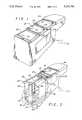
- FIG. 1is a perspective view of an armrest with a telescopic tray cover
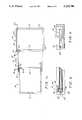
- FIG. 1ais a top view of the telescopic trays of FIG. 1, showing pins attached to the trays to limit the relative movement of the trays therein;
- FIG. 1ba side view of FIG. 1 taken at line 1b-1b, showing the relative locations of the pins at each tray;
- FIG. 1cis a side view of FIG. 1, taken at line 1c-1c, showing the movement of the pins within a slot incorporated into a tray;
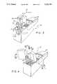
- FIG. 2is a perspective view similar to FIG. 1, showing a viewing device stored in a stowing compartment of the armrest;
- FIG. 3is a perspective view similar to FIG. 2, showing the viewing device retracted out of the stowing compartment;
- FIG. 4is a perspective view similar to FIG. 3 showing the viewing device rotated into a "viewing" position;
- FIG. 5is a cross-sectional view, showing the "pop-up" mechanism of the viewing device.
- number 10is an armrest 10, typically installed in a commercial airplane.
- the armrest 10has a telescopic tray cover 12, that can be used by passengers to support drinks, food etc.
- the telescopic tray 12has a first tray 14, a second tray 16, and a third tray 18.
- the first tray 14has a wall 19 that extends around the periphery of the tray such that the cross section of the tray is a C-channel 20, wherein the distance between the side walls 22 of the C-channel is greater than the width of the second tray 16, such that the second tray 16 can slide underneath the first tray 14.
- the second tray 16has a C-channel 20' with predetermined dimensions, such that the third tray 18 can slide underneath the second tray 16.
- the third tray 18has a wall 19 that extends all the way around the tray.
- the armrest 10may also have a cushion 24 rigidly attached to the armrest 10, to provide additional passenger comfort.
- the traysslide along the upper surface 26 of a stowing cabinet 28 and are guided by a first guide rail 30, which fits within a channel 31 in the third tray 18.
- the first 14 and second 16 traysmay also have channels 31 in the walls 19 as shown in FIG. 1a, adapted to fit within the guide rail 30 such that the rail 30 limits lateral movement of the trays.
- the guide rail 30may have a wide portion that abuts the wall 19 extending from the back of the third tray 18, when the third tray 18 is moved into the most forward position.
- the channel 31 in the front of the third tray 18being wider to allow the third tray 18 to slide over the wider portion of the guide rail 30. This arrangement prevents the third tray 18 from sliding off the stowing cabinet 28.
- the guide rail 30may be screw mounted to the stowing cabinet 28 such that the rail and trays are one unit. When the trays are in a closed position, as shown in FIG. 1, a part of the second tray 16 can be under the first tray 14, and the second tray 16 can overlap a portion of the third tray 18. As shown in FIGS.
- the third 18 and second 16 traysmay have first pins 32 that slide along grooves 33 within the second 16 and first 14 trays, respectively.
- the pins 32 and grooves 33provide means for the trays to slide relative to each other in an essentially parallel fashion.
- the first 14 and second 16 traysmay have second pins 32' at one end of the grooves 33 that abut said corresponding first pins 32 to limit the movement of the third 18 and second 16 trays as shown in FIG. 1a.
- the traysare thus constructed such that the telescopic tray 12 may operate to expose a stowing compartment 34 from either the front or the rear.
- the trayscan also move independently of each other, so that the second tray 16 can slide over the third tray 18, without moving the first tray 14.
- a stowing compartment 34 that extends the length of the armrest 10can be incorporated, wherein a stored object is easily and independently accessible from every position, from the forward or rear areas within the compartment 34.
- the traysmay have recessed areas 36 to facilitate support of the food, drinks etc.
- the stowing cabinet 28can hold viewing screens 38 such as television or computer monitors, wherein the monitors utilize "Liquid Crystal Display” (LCD) technology which allows the viewing screens to be thin and light.
- FIG. 2shows a preferred embodiment of storing the viewing screens 38 within the stowing compartment 34.
- the monitors 38may have hold tabs 39, which allows a passenger to grab the monitor 38 and pull the screens out of the stowing compartment 34 along a y axis, as shown in FIG. 3.
- FIG. 4shows how the screens 38 can then be rotated about the y axis by a first joint 40 and about the z axis by a second joint 42, such that the passengers can orient the screens 38 accordingly.
- FIGS. 2 and 5more accurately show the preferred embodiment for retracting the monitors 38 from the stowing compartment 34.
- Track 44is mounted within the compartment 34 extending up to the upper surface 26.
- Each track 44has a first groove 46 along the longitudinal axis that is adapted to allow first slide plate 48 to slide along the first groove 46.
- the first slide plate 48has a second groove 50 along the longitudinal axis adapted to allow second slide plate 52 to slide within the second groove 50.
- the track 44 and second slide plate 52have first 54 and second 56 spring loaded detents that push dowels 58 into first 60 and second 62 apertures, respectively, when the apertures align with the detents.
- the second slide plate 52slides along the second grove 50 until the second aperture 62 aligns with the second detent 56, wherein the second detent 56 snaps the dowel 58 into the aperture 62, securing the second slide plate 52 to the first slide plate 48.
- the first slide plate 48then slides along the first groove 46 of the track 44 until the first aperture 60 aligns with the first detent 54, wherein the detent 54 pushes the dowel 58 into the first aperture 60, securing the first slide plate 48 to the track 44.
- the dowels 58should have a length and radius such that the dowels 58 disengage from the apertures when a small force is applied to the monitors 38. This allows the passengers to easily detach the slide plates and push the screens 38 back into the stowing department 34.
- a first housing 64is mounted to the second slide plate 54 by a screw 66 that threads into a jam-nut 68 pressed into the second plate 54.
- the jam-nut 68is pressed into the second slide plate 54 with a predetermined force, such that a corresponding force applied to the screen 38 will pull the nut 68 out of the plate 52 and separate the screen 38 from the armrest 10. This feature allows the display to meet safety requirements, that all protruding equipment must be capable of being pushed away, in the event the passenger is subjected to conditions such as turbulent weather.
- the first housing 64has a first bore 70 along the longitudinal axis.
- first bearing 72having a cylindrical shank 74 within the first housing 64 and a first flange 76 extending from the first housing 64.
- the first housing 64has a first threaded aperture 78 that receives a first set screw 80.
- the first set screw 80extends into a first groove 82 that goes around the periphery of the bearing shank 74.
- the first screw 80holds the first bearing 72 within the first housing 64, while allowing the bearing 72 to rotate about the y axis of the first housing 64.
- second housing 84On top of the first housing 64 is a second housing 84 having a second bore 86.
- a second bearing 88having a shank 90 within the second housing 84 and a second flange 92 extending from the second housing 84 and attached to the monitor 38.
- the first flange 76 of the first bearing 72has a second threaded aperture 94 that receives a second set screw 96.
- the second set screw 96extends into a second groove 98 that goes around the periphery of the bearing shank 90.
- the second set screw 96insures that the second bearing 88 does not fall out of the second housing 84 while allowing the second bearing 88 to rotate relative to the second housing 84.
- the second housing 84also has a third bore 100 that receives the first flange 76 of the first bearing 72.
- the flange 76 and third bore 100being of such dimension, that the flange 76 has a snug fit within the second housing 84, attaching the first bearing 72 to the second housing 84, wherein the second bearing 88 is attached to the second housing 84 through the first flange 76 and second set screw 96.
- the top or bottom of the screen 38can be pushed or pulled, wherein the screen 38 and attached second bearing 88 rotate relative to the second housing 84.
- Pushing or pulling the end of the monitor 38will rotate the second housing 84 and first bearing 72 relative to the first housing 64, rotating the screen 38 about the y-axis as indicated in FIG. 4.
- the telescopic trays 12can be slid back as shown in FIG. 4, allowing the user to utilize the trays to set down drinks, books, etc. while still viewing the screen 38.
- the first 72 and second 88 bearingsmay have third 102 and fourth 104 bores, respectively, to allow electrical cable 106 access from an external source to the monitor 38.
- the cable 106may have a conduit 108 that attaches to the first bearing 72 within a counterbore 110 of the bearing.
- the combination of the hidden set screws and covered cableprovides an aesthetic design devoid of exposed wires or fasteners.
- a third 112 and fourth 114 groove with accompanying O-rings 116 inserted,can be added to the first 64 and second 84 housings, respectively.
- the O-ringsprovide frictional forces between the housings and the respective bearings, such that when the monitor 38 is rotated the O-rings will "hold” the screen in place. This provides semi-rigid adjustment means for the monitor 38.
- a mechanism that will retract a viewing monitor from a stowing compartmentthat allows easy adjustment of the screen and utilization of trays to maximize user comfort.
Landscapes
- Engineering & Computer Science (AREA)
- Aviation & Aerospace Engineering (AREA)
- Transportation (AREA)
- Mechanical Engineering (AREA)
- Vehicle Step Arrangements And Article Storage (AREA)
Abstract
Description
This is a divisional of application Ser. No. 07/635,691, filed Dec. 27, 1990 now U.S. Pat. No. 5,076,524 issued Dec. 31, 1991.
1. Field of the Invention
This invention relates to armrest storage compartments typically used in commercial aircraft, which have the additional feature of having a tray for drinks, food etc.
2. Description of the Related Art
As airplanes increasingly become the mode of travel, airlines are constantly improving passenger comfort and convenience. The development of "Liquid Crystal Display" (LCD) screens, which are both thin and light, will allow the industry to provide each individual with their own screen. Because of safety requirements and customer convenience, the screen must be easily stored and retracted. What is preferred, is a design wherein the screen is stored in the armrest of the seat. Some seats, particularly in first class, have trays on the upper surface of the armrest that hold food, drinks etc. To maximize passenger comfort, it is desirable to provide an armrest, where the viewer can watch the screen while still being able to rest their food or drinks on the tray.
Therefore it is an object of this invention to provide an armrest that can display a viewing device stored within the armrest, while providing a tray to support items of the passenger.
This invention is an armrest that has a plurality of telescopic trays that collapse to allow a viewing device to be retracted from a stowing compartment within the armrest. The telescopic trays can then be rolled back while the viewing device is displayed, allowing the passenger to utilize both the monitor and the trays. The viewing device is connected to a slide plate that slides along a track that is mounted within the stowing compartment. The plate and track allow the monitor to be retracted from the compartment. The viewing device is also attached to a pair of joints, such that the device can be rotated about the x, y and z axis, to allow the passenger to display and move the monitor into the most comfortable position.
The objects and advantages of this invention will become more readily apparent to those skilled in the art after reviewing the following detailed description and accompanying drawings, wherein:
FIG. 1 is a perspective view of an armrest with a telescopic tray cover;
FIG. 1a is a top view of the telescopic trays of FIG. 1, showing pins attached to the trays to limit the relative movement of the trays therein;
FIG. 1b a side view of FIG. 1 taken at line 1b-1b, showing the relative locations of the pins at each tray;
FIG. 1c is a side view of FIG. 1, taken at line 1c-1c, showing the movement of the pins within a slot incorporated into a tray;
FIG. 2 is a perspective view similar to FIG. 1, showing a viewing device stored in a stowing compartment of the armrest;
FIG. 3 is a perspective view similar to FIG. 2, showing the viewing device retracted out of the stowing compartment;
FIG. 4 is a perspective view similar to FIG. 3 showing the viewing device rotated into a "viewing" position;
FIG. 5 is a cross-sectional view, showing the "pop-up" mechanism of the viewing device.
Referring to the drawings more particularly by reference numbers,number 10 is anarmrest 10, typically installed in a commercial airplane. Thearmrest 10 has atelescopic tray cover 12, that can be used by passengers to support drinks, food etc. In the preferred embodiment thetelescopic tray 12 has afirst tray 14, asecond tray 16, and athird tray 18. As shown in FIG. 1a thefirst tray 14 has awall 19 that extends around the periphery of the tray such that the cross section of the tray is a C-channel 20, wherein the distance between theside walls 22 of the C-channel is greater than the width of thesecond tray 16, such that thesecond tray 16 can slide underneath thefirst tray 14. Likewise, thesecond tray 16 has a C-channel 20' with predetermined dimensions, such that thethird tray 18 can slide underneath thesecond tray 16. Thethird tray 18 has awall 19 that extends all the way around the tray. Thearmrest 10 may also have acushion 24 rigidly attached to thearmrest 10, to provide additional passenger comfort. As shown in FIG. 2, the trays slide along theupper surface 26 of astowing cabinet 28 and are guided by afirst guide rail 30, which fits within achannel 31 in thethird tray 18. The first 14 and second 16 trays may also havechannels 31 in thewalls 19 as shown in FIG. 1a, adapted to fit within theguide rail 30 such that therail 30 limits lateral movement of the trays. Theguide rail 30 may have a wide portion that abuts thewall 19 extending from the back of thethird tray 18, when thethird tray 18 is moved into the most forward position. Thechannel 31 in the front of thethird tray 18 being wider to allow thethird tray 18 to slide over the wider portion of theguide rail 30. This arrangement prevents thethird tray 18 from sliding off thestowing cabinet 28. Theguide rail 30 may be screw mounted to thestowing cabinet 28 such that the rail and trays are one unit. When the trays are in a closed position, as shown in FIG. 1, a part of thesecond tray 16 can be under thefirst tray 14, and thesecond tray 16 can overlap a portion of thethird tray 18. As shown in FIGS. 1a-1c, the third 18 and second 16 trays may havefirst pins 32 that slide alonggrooves 33 within the second 16 and first 14 trays, respectively. Thepins 32 andgrooves 33 provide means for the trays to slide relative to each other in an essentially parallel fashion. The first 14 and second 16 trays may have second pins 32' at one end of thegrooves 33 that abut said correspondingfirst pins 32 to limit the movement of the third 18 and second 16 trays as shown in FIG. 1a. The trays are thus constructed such that thetelescopic tray 12 may operate to expose astowing compartment 34 from either the front or the rear. The trays can also move independently of each other, so that thesecond tray 16 can slide over thethird tray 18, without moving thefirst tray 14. Thus astowing compartment 34 that extends the length of thearmrest 10 can be incorporated, wherein a stored object is easily and independently accessible from every position, from the forward or rear areas within thecompartment 34. The trays may have recessedareas 36 to facilitate support of the food, drinks etc.
Thestowing cabinet 28 can holdviewing screens 38 such as television or computer monitors, wherein the monitors utilize "Liquid Crystal Display" (LCD) technology which allows the viewing screens to be thin and light. FIG. 2 shows a preferred embodiment of storing theviewing screens 38 within thestowing compartment 34. Themonitors 38 may have holdtabs 39, which allows a passenger to grab themonitor 38 and pull the screens out of thestowing compartment 34 along a y axis, as shown in FIG. 3. FIG. 4 shows how thescreens 38 can then be rotated about the y axis by afirst joint 40 and about the z axis by asecond joint 42, such that the passengers can orient thescreens 38 accordingly.
FIGS. 2 and 5 more accurately show the preferred embodiment for retracting themonitors 38 from thestowing compartment 34.Track 44 is mounted within thecompartment 34 extending up to theupper surface 26. Eachtrack 44 has afirst groove 46 along the longitudinal axis that is adapted to allowfirst slide plate 48 to slide along thefirst groove 46. Thefirst slide plate 48 has asecond groove 50 along the longitudinal axis adapted to allowsecond slide plate 52 to slide within thesecond groove 50. Thetrack 44 andsecond slide plate 52 have first 54 and second 56 spring loaded detents that push dowels 58 into first 60 and second 62 apertures, respectively, when the apertures align with the detents. In operation, when themonitor 38 is pulled up, thesecond slide plate 52 slides along thesecond grove 50 until thesecond aperture 62 aligns with thesecond detent 56, wherein thesecond detent 56 snaps thedowel 58 into theaperture 62, securing thesecond slide plate 52 to thefirst slide plate 48. Thefirst slide plate 48 then slides along thefirst groove 46 of thetrack 44 until thefirst aperture 60 aligns with thefirst detent 54, wherein thedetent 54 pushes thedowel 58 into thefirst aperture 60, securing thefirst slide plate 48 to thetrack 44. Thedowels 58 should have a length and radius such that thedowels 58 disengage from the apertures when a small force is applied to themonitors 38. This allows the passengers to easily detach the slide plates and push thescreens 38 back into thestowing department 34.
Afirst housing 64 is mounted to thesecond slide plate 54 by ascrew 66 that threads into a jam-nut 68 pressed into thesecond plate 54. The jam-nut 68 is pressed into thesecond slide plate 54 with a predetermined force, such that a corresponding force applied to thescreen 38 will pull thenut 68 out of theplate 52 and separate thescreen 38 from thearmrest 10. This feature allows the display to meet safety requirements, that all protruding equipment must be capable of being pushed away, in the event the passenger is subjected to conditions such as turbulent weather. Thefirst housing 64 has a first bore 70 along the longitudinal axis. Within the first bore 70 is afirst bearing 72 having acylindrical shank 74 within thefirst housing 64 and afirst flange 76 extending from thefirst housing 64. Thefirst housing 64 has a first threadedaperture 78 that receives afirst set screw 80. Thefirst set screw 80 extends into afirst groove 82 that goes around the periphery of the bearingshank 74. Thefirst screw 80 holds thefirst bearing 72 within thefirst housing 64, while allowing the bearing 72 to rotate about the y axis of thefirst housing 64. On top of thefirst housing 64 is asecond housing 84 having asecond bore 86. Within thesecond bore 86 is asecond bearing 88 having ashank 90 within thesecond housing 84 and asecond flange 92 extending from thesecond housing 84 and attached to themonitor 38. Thefirst flange 76 of thefirst bearing 72 has a second threadedaperture 94 that receives asecond set screw 96. Thesecond set screw 96 extends into asecond groove 98 that goes around the periphery of the bearingshank 90. Thesecond set screw 96 insures that thesecond bearing 88 does not fall out of thesecond housing 84 while allowing thesecond bearing 88 to rotate relative to thesecond housing 84. Thesecond housing 84 also has athird bore 100 that receives thefirst flange 76 of thefirst bearing 72. Theflange 76 andthird bore 100 being of such dimension, that theflange 76 has a snug fit within thesecond housing 84, attaching thefirst bearing 72 to thesecond housing 84, wherein thesecond bearing 88 is attached to thesecond housing 84 through thefirst flange 76 andsecond set screw 96. To rotate thescreen 38 about the x or z axis, the top or bottom of thescreen 38 can be pushed or pulled, wherein thescreen 38 and attachedsecond bearing 88 rotate relative to thesecond housing 84. Pushing or pulling the end of themonitor 38, will rotate thesecond housing 84 andfirst bearing 72 relative to thefirst housing 64, rotating thescreen 38 about the y-axis as indicated in FIG. 4. After themonitor 38 is retracted and displayed, thetelescopic trays 12 can be slid back as shown in FIG. 4, allowing the user to utilize the trays to set down drinks, books, etc. while still viewing thescreen 38.
The first 72 and second 88 bearings may have third 102 and fourth 104 bores, respectively, to allowelectrical cable 106 access from an external source to themonitor 38. Thecable 106 may have aconduit 108 that attaches to thefirst bearing 72 within a counterbore 110 of the bearing. The combination of the hidden set screws and covered cable provides an aesthetic design devoid of exposed wires or fasteners.
A third 112 and fourth 114 groove with accompanying O-rings 116 inserted, can be added to the first 64 and second 84 housings, respectively. The O-rings provide frictional forces between the housings and the respective bearings, such that when themonitor 38 is rotated the O-rings will "hold" the screen in place. This provides semi-rigid adjustment means for themonitor 38. Thus what is provided is a mechanism that will retract a viewing monitor from a stowing compartment, that allows easy adjustment of the screen and utilization of trays to maximize user comfort.
While certain exemplary embodiments of the invention have been described above and shown in the accompanying drawings, it is to be understood that such embodiments are merely illustrative of, and not restrictive on the broad invention, and that this invention not be limited to the specific constructions or arrangements shown and described, since various other modifications may occur to persons having ordinary skill in the art.
Claims (9)
1. A telescopic tray cover attached to an armrest having an upper surface, comprising:
a rail coupled to the armrest;
a first tray adapted to slide along the upper surface of the armrest, said first tray having a top surface, said first tray having a first channel that receives said rail and guides said first tray; and
at least one second tray adapted to slide along the upper surface of the armrest, said second tray having a top surface, said first tray and said second tray being constructed such that said first tray overlaps said second tray when said trays slide relative to each other, said second tray having a second channel that receives said rail and guides said second tray.
2. The telescopic tray cover as recited in claim 1, wherein the cross-section of said first tray is a C-channel having a predetermined distance between flanges of said C-channel greater than the width of said second tray, to allow said second tray to slide under said first tray.
3. The telescopic tray cover as recited in claim 1, further comprising a third tray having a top surface, said third tray being adapted to slide along the upper surface of the armrest, said third tray and said second tray being constructed such that said second tray overlaps said third tray when the telescopic tray cover is in an open position, said third tray having a third channel that receives said rail and guides said third tray.
4. The telescopic tray cover as recited in claim 3, wherein the cross-section of said second tray is a C-channel having a predetermined distance between flanges of said C-channel greater than the width of said third tray, to allow said third tray to slide under said second tray.
5. The telescopic tray cover as recited in claim 3, wherein said third tray has at least one pin that extends into and slides along a groove in said second tray and said second tray has at least one pin that extends into and slides along a groove in said first tray such that said trays slide essentially parallel to each other.
6. The telescopic tray cover as recited in claim 3, wherein said first try, said second tray and said third tray have a recessed area on said top surfaces.
7. A telescopic tray cover attached to an armrest having an upper surface, comprising:
a first tray adapted to slide along the upper surface of the armrest, said first tray having a cross-section shaped as a C-channel having a first predetermined distance between flanges of said C-channel, said first tray further a first groove;
a second tray adapted to slide along the upper surface of the armrest, said second tray having a width less than said first predetermined distance between said C-channel flanges of said first tray such that said second tray can slide under said first tray, said second tray having a cross-section shaped as a C-channel having a second predetermined distance between flanges of said C-channel, said second tray further having a second groove and a first pin that extends into said first groove of said first tray; and
a third tray adapted to slide along the upper surface of the armrest, said third tray having a width less than said second predetermined distance between said C-channel flanges of said second tray such that said third tray can slide under said second tray, said third tray having a second pin that extends into said second groove of said second tray.
8. The telescopic tray cover as recited in claim 8, wherein said first, second and third trays have channels and the armrest has a rail adapted to fit within said channels, wherein said first, second and third trays are guided by said rail.
9. The telescopic tray cover as recited in claim 8, further comprising a cushion rigidly attached to the armrest.
Priority Applications (1)
| Application Number | Priority Date | Filing Date | Title |
|---|---|---|---|
| US07/767,233US5222780A (en) | 1990-12-27 | 1991-09-27 | TV/LCD pop-up stowage retraction means |
Applications Claiming Priority (2)
| Application Number | Priority Date | Filing Date | Title |
|---|---|---|---|
| US07/635,691US5076524A (en) | 1990-12-27 | 1990-12-27 | TV/LCD pop-up stowage retraction means |
| US07/767,233US5222780A (en) | 1990-12-27 | 1991-09-27 | TV/LCD pop-up stowage retraction means |
Related Parent Applications (1)
| Application Number | Title | Priority Date | Filing Date |
|---|---|---|---|
| US07/635,691DivisionUS5076524A (en) | 1990-12-27 | 1990-12-27 | TV/LCD pop-up stowage retraction means |
Publications (1)
| Publication Number | Publication Date |
|---|---|
| US5222780Atrue US5222780A (en) | 1993-06-29 |
Family
ID=27092430
Family Applications (1)
| Application Number | Title | Priority Date | Filing Date |
|---|---|---|---|
| US07/767,233Expired - LifetimeUS5222780A (en) | 1990-12-27 | 1991-09-27 | TV/LCD pop-up stowage retraction means |
Country Status (1)
| Country | Link |
|---|---|
| US (1) | US5222780A (en) |
Cited By (40)
| Publication number | Priority date | Publication date | Assignee | Title |
|---|---|---|---|---|
| USD367477S (en) | 1994-09-30 | 1996-02-27 | Rosen John B | Monitor support |
| US5607213A (en)* | 1995-04-03 | 1997-03-04 | Snap-On Technologies, Inc. | Sliding drawer tray |
| US5667179A (en)* | 1994-09-30 | 1997-09-16 | Rosen; John B. | Ratcheting articulable monitor support and presentation device |
| USD386158S (en)* | 1996-06-19 | 1997-11-11 | Rosen John B | Combined monitor and support |
| USD387345S (en)* | 1996-11-14 | 1997-12-09 | Rosen John B | Stowable monitor mount |
| US5709360A (en)* | 1994-09-30 | 1998-01-20 | Rosen; John B. | Ratcheting articulable monitor support and presentation device |
| USD391148S (en) | 1997-05-08 | 1998-02-24 | Advanced Multimedia Products Corporation | Monitor support arm |
| USD391951S (en) | 1996-11-14 | 1998-03-10 | Advanced Multimedia Products Corporation | Stowable table top monitor |
| USD391945S (en) | 1997-02-06 | 1998-03-10 | Advanced Multimedia Products Corporation | Monitor support |
| USD391937S (en) | 1996-04-19 | 1998-03-10 | Advanced Multimedia Products Corporation | Monitor support |
| US5845965A (en)* | 1997-01-16 | 1998-12-08 | Ford Motor Company | Adjustable armrest for automobile console |
| DE19754224A1 (en)* | 1997-12-06 | 1999-06-10 | Volkswagen Ag | Computer screen workstation for motor vehicle |
| USD412899S (en) | 1998-02-18 | 1999-08-17 | Rosen Products Llc | Deployable display |
| US5941488A (en)* | 1997-06-20 | 1999-08-24 | Rosen Product Development, Inc. | Monitor support with self-positioning guide track |
| US5996954A (en)* | 1997-10-14 | 1999-12-07 | Rosen Products Llc | Stowable support apparatus |
| USD427604S (en)* | 1998-02-23 | 2000-07-04 | Rosen Products Llc | Monitor support arm |
| US6102476A (en)* | 1998-03-11 | 2000-08-15 | May; Gordon G. | Computer furniture with integrated computer |
| US6219866B1 (en)* | 1999-03-29 | 2001-04-24 | Leroy Pascal | Infant lapmate |
| DE19951307A1 (en)* | 1999-10-25 | 2001-04-26 | Wilkhahn Wilkening & Hahne | Chair holding flat screen, can be coupled to second screen held on second chair assisting e.g. data or information exchange |
| US20010017761A1 (en)* | 1993-06-29 | 2001-08-30 | Ditzik Richard J. | Desktop device with adjustable flat panel screen |
| USD460055S1 (en) | 1997-06-20 | 2002-07-09 | Rosen Products, Llc | Pedestal monitor |
| US20040075639A1 (en)* | 2002-10-17 | 2004-04-22 | Thales Avionics In-Flight Systems, Llc | Display retract mechanism |
| US20050225130A1 (en)* | 2004-03-31 | 2005-10-13 | Hideki Kobayashi | Console for vehicle |
| US20050231008A1 (en)* | 2004-04-20 | 2005-10-20 | Jaaska John P Sr | Pivotable rear seat armrest with integrated entertainment system |
| US20060258441A1 (en)* | 2005-04-20 | 2006-11-16 | Vitito Christopher J | Vehicle entertainment system incorporated within the armrest/console of a vehicle |
| US20060258440A1 (en)* | 2005-04-20 | 2006-11-16 | Vitito Christopher J | Detachable vehicle entertainment system for the armrest/console of a vehicle |
| US7178871B1 (en)* | 1998-10-15 | 2007-02-20 | British Airways Plc | Seating unit |
| US20070063553A1 (en)* | 2005-09-22 | 2007-03-22 | Lev Lilov | Vehicle console |
| US20080309820A1 (en)* | 2007-06-14 | 2008-12-18 | Panasonic Automotive Systems Co. of America ˜ Division of Panasonic Corp. of North America | Dual display multi-modal vehicle infotainment system |
| US7568760B1 (en) | 2007-06-04 | 2009-08-04 | Lodes Mark P | Apparatus for converting an armchair for use as a computer workplace |
| US7604291B2 (en) | 2005-04-20 | 2009-10-20 | Vitito Christopher J | Vehicle entertainment system incorporated within the armrest/console of a vehicle with a swivel monitor mounting structure |
| US20090302158A1 (en)* | 2005-12-23 | 2009-12-10 | British Airways Plc | Aircraft Passenger Seat |
| USRE42091E1 (en) | 1998-11-20 | 2011-02-01 | Jerry Moscovitch | Computer display screen system and adjustable screen mount, and swinging screens therefor |
| US8184974B2 (en) | 2006-09-11 | 2012-05-22 | Lumexis Corporation | Fiber-to-the-seat (FTTS) fiber distribution system |
| US8416698B2 (en) | 2009-08-20 | 2013-04-09 | Lumexis Corporation | Serial networking fiber optic inflight entertainment system network configuration |
| US8424045B2 (en) | 2009-08-14 | 2013-04-16 | Lumexis Corporation | Video display unit docking assembly for fiber-to-the-screen inflight entertainment system |
| US8462103B1 (en) | 1998-12-23 | 2013-06-11 | Jerry Moscovitch | Computer display screen system and adjustable screen mount, and swinging screens therefor |
| US8659990B2 (en) | 2009-08-06 | 2014-02-25 | Lumexis Corporation | Serial networking fiber-to-the-seat inflight entertainment system |
| US9910280B2 (en)* | 2013-06-18 | 2018-03-06 | Minebea Co., Ltd. | Display device |
| CN111516571A (en)* | 2020-04-12 | 2020-08-11 | 宁波吉利汽车研究开发有限公司 | An armrest box lighting device |
Citations (4)
| Publication number | Priority date | Publication date | Assignee | Title |
|---|---|---|---|---|
| US1869444A (en)* | 1930-12-12 | 1932-08-02 | Macey Company | Tablet for armchairs |
| US1958795A (en)* | 1932-06-13 | 1934-05-15 | William A Lyle | Barber chair attachment |
| US3064373A (en)* | 1959-03-26 | 1962-11-20 | Virginia R Spain | Collapsible ironing board |
| US3237824A (en)* | 1964-11-12 | 1966-03-01 | Daniel E Gunckel | Container for automobile |
- 1991
- 1991-09-27USUS07/767,233patent/US5222780A/ennot_activeExpired - Lifetime
Patent Citations (4)
| Publication number | Priority date | Publication date | Assignee | Title |
|---|---|---|---|---|
| US1869444A (en)* | 1930-12-12 | 1932-08-02 | Macey Company | Tablet for armchairs |
| US1958795A (en)* | 1932-06-13 | 1934-05-15 | William A Lyle | Barber chair attachment |
| US3064373A (en)* | 1959-03-26 | 1962-11-20 | Virginia R Spain | Collapsible ironing board |
| US3237824A (en)* | 1964-11-12 | 1966-03-01 | Daniel E Gunckel | Container for automobile |
Cited By (60)
| Publication number | Priority date | Publication date | Assignee | Title |
|---|---|---|---|---|
| US7091961B2 (en) | 1993-06-29 | 2006-08-15 | Ditzik Richard J | Desktop device with adjustable flat screen display |
| US20060187626A1 (en)* | 1993-06-29 | 2006-08-24 | Ditzik Richard J | Desktop device with adjustable flat screen display |
| US20010017761A1 (en)* | 1993-06-29 | 2001-08-30 | Ditzik Richard J. | Desktop device with adjustable flat panel screen |
| US5667179A (en)* | 1994-09-30 | 1997-09-16 | Rosen; John B. | Ratcheting articulable monitor support and presentation device |
| US5709360A (en)* | 1994-09-30 | 1998-01-20 | Rosen; John B. | Ratcheting articulable monitor support and presentation device |
| USD367477S (en) | 1994-09-30 | 1996-02-27 | Rosen John B | Monitor support |
| US5607213A (en)* | 1995-04-03 | 1997-03-04 | Snap-On Technologies, Inc. | Sliding drawer tray |
| USD391937S (en) | 1996-04-19 | 1998-03-10 | Advanced Multimedia Products Corporation | Monitor support |
| USD386158S (en)* | 1996-06-19 | 1997-11-11 | Rosen John B | Combined monitor and support |
| USD391951S (en) | 1996-11-14 | 1998-03-10 | Advanced Multimedia Products Corporation | Stowable table top monitor |
| USD387345S (en)* | 1996-11-14 | 1997-12-09 | Rosen John B | Stowable monitor mount |
| EP0854064A3 (en)* | 1997-01-16 | 1999-05-06 | Ford Motor Company | Adjustable armrest for automobile console |
| US5845965A (en)* | 1997-01-16 | 1998-12-08 | Ford Motor Company | Adjustable armrest for automobile console |
| USD391945S (en) | 1997-02-06 | 1998-03-10 | Advanced Multimedia Products Corporation | Monitor support |
| USD391148S (en) | 1997-05-08 | 1998-02-24 | Advanced Multimedia Products Corporation | Monitor support arm |
| USD460055S1 (en) | 1997-06-20 | 2002-07-09 | Rosen Products, Llc | Pedestal monitor |
| US5941488A (en)* | 1997-06-20 | 1999-08-24 | Rosen Product Development, Inc. | Monitor support with self-positioning guide track |
| US5996954A (en)* | 1997-10-14 | 1999-12-07 | Rosen Products Llc | Stowable support apparatus |
| US6179263B1 (en) | 1997-10-14 | 2001-01-30 | Rosen Products Llc | Stowable support apparatus |
| DE19754224B4 (en)* | 1997-12-06 | 2007-03-15 | Volkswagen Ag | Computer workstation in a vehicle |
| DE19754224A1 (en)* | 1997-12-06 | 1999-06-10 | Volkswagen Ag | Computer screen workstation for motor vehicle |
| USD412899S (en) | 1998-02-18 | 1999-08-17 | Rosen Products Llc | Deployable display |
| USD427604S (en)* | 1998-02-23 | 2000-07-04 | Rosen Products Llc | Monitor support arm |
| US6102476A (en)* | 1998-03-11 | 2000-08-15 | May; Gordon G. | Computer furniture with integrated computer |
| US7178871B1 (en)* | 1998-10-15 | 2007-02-20 | British Airways Plc | Seating unit |
| USRE42091E1 (en) | 1998-11-20 | 2011-02-01 | Jerry Moscovitch | Computer display screen system and adjustable screen mount, and swinging screens therefor |
| US8462103B1 (en) | 1998-12-23 | 2013-06-11 | Jerry Moscovitch | Computer display screen system and adjustable screen mount, and swinging screens therefor |
| US6219866B1 (en)* | 1999-03-29 | 2001-04-24 | Leroy Pascal | Infant lapmate |
| DE19951307A1 (en)* | 1999-10-25 | 2001-04-26 | Wilkhahn Wilkening & Hahne | Chair holding flat screen, can be coupled to second screen held on second chair assisting e.g. data or information exchange |
| US20060203135A1 (en)* | 2002-10-17 | 2006-09-14 | Radioshack Corporation | Apparatus and method for effecting communication between a wireless network and a satellite radio receiver |
| US20080036924A9 (en)* | 2002-10-17 | 2008-02-14 | Thales Avionics, Inc. | Display retract mechanism |
| US20040075639A1 (en)* | 2002-10-17 | 2004-04-22 | Thales Avionics In-Flight Systems, Llc | Display retract mechanism |
| US7042528B2 (en) | 2002-10-17 | 2006-05-09 | Thales Avionics, Inc. | Display retract mechanism |
| US7405773B2 (en) | 2002-10-17 | 2008-07-29 | Thales Avionics, Inc. | Display retract mechanism |
| US7114772B2 (en)* | 2004-03-31 | 2006-10-03 | Honda Access Corporation | Console for vehicle |
| US20050225130A1 (en)* | 2004-03-31 | 2005-10-13 | Hideki Kobayashi | Console for vehicle |
| US6997508B2 (en)* | 2004-04-20 | 2006-02-14 | Visteon Global Technologies, Inc. | Pivotable rear seat armrest with integrated entertainment system |
| US20050231008A1 (en)* | 2004-04-20 | 2005-10-20 | Jaaska John P Sr | Pivotable rear seat armrest with integrated entertainment system |
| US7857382B2 (en) | 2005-04-20 | 2010-12-28 | Audiovox Corporation | Detachable vehicle entertainment system for the armrest/console of a vehicle |
| US20060258440A1 (en)* | 2005-04-20 | 2006-11-16 | Vitito Christopher J | Detachable vehicle entertainment system for the armrest/console of a vehicle |
| US20060258441A1 (en)* | 2005-04-20 | 2006-11-16 | Vitito Christopher J | Vehicle entertainment system incorporated within the armrest/console of a vehicle |
| US7604291B2 (en) | 2005-04-20 | 2009-10-20 | Vitito Christopher J | Vehicle entertainment system incorporated within the armrest/console of a vehicle with a swivel monitor mounting structure |
| US8070224B2 (en) | 2005-04-20 | 2011-12-06 | Audiovox Corporation | Vehicle entertainment system incorporated within the armrest/console of a vehicle |
| US7278681B2 (en)* | 2005-09-22 | 2007-10-09 | Nyx, Inc. | Vehicle console |
| US20070063553A1 (en)* | 2005-09-22 | 2007-03-22 | Lev Lilov | Vehicle console |
| US20090302158A1 (en)* | 2005-12-23 | 2009-12-10 | British Airways Plc | Aircraft Passenger Seat |
| US8616643B2 (en) | 2005-12-23 | 2013-12-31 | British Airways Plc | Aircraft passenger seat |
| US8184974B2 (en) | 2006-09-11 | 2012-05-22 | Lumexis Corporation | Fiber-to-the-seat (FTTS) fiber distribution system |
| US7568760B1 (en) | 2007-06-04 | 2009-08-04 | Lodes Mark P | Apparatus for converting an armchair for use as a computer workplace |
| US8363170B2 (en)* | 2007-06-14 | 2013-01-29 | Panasonic Automotive Systems Company Of America, Division Of Panasonic Corporation Of North America | Dual display multi-modal vehicle infotainment system |
| US20080309820A1 (en)* | 2007-06-14 | 2008-12-18 | Panasonic Automotive Systems Co. of America ˜ Division of Panasonic Corp. of North America | Dual display multi-modal vehicle infotainment system |
| US9118547B2 (en) | 2009-08-06 | 2015-08-25 | Lumexis Corporation | Serial networking fiber-to-the-seat inflight entertainment system |
| US8659990B2 (en) | 2009-08-06 | 2014-02-25 | Lumexis Corporation | Serial networking fiber-to-the-seat inflight entertainment system |
| US9532082B2 (en) | 2009-08-06 | 2016-12-27 | Lumexis Corporation | Serial networking fiber-to-the-seat inflight entertainment system |
| US8424045B2 (en) | 2009-08-14 | 2013-04-16 | Lumexis Corporation | Video display unit docking assembly for fiber-to-the-screen inflight entertainment system |
| US8416698B2 (en) | 2009-08-20 | 2013-04-09 | Lumexis Corporation | Serial networking fiber optic inflight entertainment system network configuration |
| US9344351B2 (en) | 2009-08-20 | 2016-05-17 | Lumexis Corporation | Inflight entertainment system network configurations |
| US9036487B2 (en) | 2009-08-20 | 2015-05-19 | Lumexis Corporation | Serial networking fiber optic inflight entertainment system network configuration |
| US9910280B2 (en)* | 2013-06-18 | 2018-03-06 | Minebea Co., Ltd. | Display device |
| CN111516571A (en)* | 2020-04-12 | 2020-08-11 | 宁波吉利汽车研究开发有限公司 | An armrest box lighting device |
Similar Documents
| Publication | Publication Date | Title |
|---|---|---|
| US5222780A (en) | TV/LCD pop-up stowage retraction means | |
| US5076524A (en) | TV/LCD pop-up stowage retraction means | |
| US5850997A (en) | Articulable projecting plug | |
| EP0577825B1 (en) | Articulable projecting plug | |
| US10377494B2 (en) | Aircraft divider assembly | |
| US5000511A (en) | Apparatus for attaching a display monitor to a seat | |
| EP2879907B1 (en) | Passenger suite seating arrangement with moveable video monitor | |
| US8979189B2 (en) | Cantilevered tray table and aircraft passenger suite including the same | |
| US9242733B2 (en) | Tray table with articulating support | |
| US20160176356A1 (en) | Adjustable support assemblies for portable electronic devices | |
| US10023315B2 (en) | Passenger seat table assembly | |
| DE102018210642B4 (en) | KITCHEN MONUMENT FOR AN AIRCRAFT AND AIRCRAFT | |
| CA2810433A1 (en) | Docking station for a video monitor | |
| EP3221188B1 (en) | Vehicle seat comprising integrated holder for electronic devices | |
| US10532816B2 (en) | Amenities modules | |
| WO2020263266A1 (en) | Portable electronic device holder for seat | |
| WO2004113168A1 (en) | A stowable table for a vehicle | |
| US5337676A (en) | Track device for mounting an entertainment module in chairs slotted | |
| GB2576505A (en) | Slide assembly with deployable cover | |
| CN113247266A (en) | A sectional sofa aircraft seat for aircraft cabin external member | |
| US20230294583A1 (en) | Modular tray table with rotational displacement mechanism | |
| US20040217676A1 (en) | Computer workstation for use in aircraft | |
| EP4292880A1 (en) | Deployable tray table | |
| EP4321437A1 (en) | Split cabin attendant seat | |
| WO2020079405A1 (en) | Aircraft passenger seat unit |
Legal Events
| Date | Code | Title | Description |
|---|---|---|---|
| STCF | Information on status: patent grant | Free format text:PATENTED CASE | |
| FEPP | Fee payment procedure | Free format text:PAYOR NUMBER ASSIGNED (ORIGINAL EVENT CODE: ASPN); ENTITY STATUS OF PATENT OWNER: LARGE ENTITY | |
| FPAY | Fee payment | Year of fee payment:4 | |
| FPAY | Fee payment | Year of fee payment:8 | |
| AS | Assignment | Owner name:ROCKWELL COLLINS, INC., IOWA Free format text:INTELLECTUAL PROPERTY AGREEMENT;ASSIGNOR:SONY CORPORATION;REEL/FRAME:013011/0705 Effective date:20000728 | |
| REMI | Maintenance fee reminder mailed | ||
| FPAY | Fee payment | Year of fee payment:12 | |
| SULP | Surcharge for late payment | Year of fee payment:11 | |
| AS | Assignment | Owner name:ROCKWELL COLLINS, INC., IOWA Free format text:CORRECTIVE ASSIGNMENT TO CORRECT THE NAME OF CONVEYING PARTY ON COVER PAGE WAS TYPED INCORRECTLY PREVIOUSLY RECORDED ON REEL 013011 FRAME 0705;ASSIGNOR:SONY TRANS COM;REEL/FRAME:022277/0807 Effective date:20000728 |