US5222048A - Method for determining borehole fluid influx - Google Patents
Method for determining borehole fluid influxDownload PDFInfo
- Publication number
- US5222048A US5222048AUS07/611,036US61103690AUS5222048AUS 5222048 AUS5222048 AUS 5222048AUS 61103690 AUS61103690 AUS 61103690AUS 5222048 AUS5222048 AUS 5222048A
- Authority
- US
- United States
- Prior art keywords
- annulus
- transfer function
- signal
- transmitted
- drill string
- Prior art date
- Legal status (The legal status is an assumption and is not a legal conclusion. Google has not performed a legal analysis and makes no representation as to the accuracy of the status listed.)
- Expired - Fee Related
Links
Images

Classifications
- E—FIXED CONSTRUCTIONS
- E21—EARTH OR ROCK DRILLING; MINING
- E21B—EARTH OR ROCK DRILLING; OBTAINING OIL, GAS, WATER, SOLUBLE OR MELTABLE MATERIALS OR A SLURRY OF MINERALS FROM WELLS
- E21B47/00—Survey of boreholes or wells
- E21B47/10—Locating fluid leaks, intrusions or movements
- E21B47/107—Locating fluid leaks, intrusions or movements using acoustic means
- E—FIXED CONSTRUCTIONS
- E21—EARTH OR ROCK DRILLING; MINING
- E21B—EARTH OR ROCK DRILLING; OBTAINING OIL, GAS, WATER, SOLUBLE OR MELTABLE MATERIALS OR A SLURRY OF MINERALS FROM WELLS
- E21B47/00—Survey of boreholes or wells
- E21B47/12—Means for transmitting measuring-signals or control signals from the well to the surface, or from the surface to the well, e.g. for logging while drilling
- E21B47/14—Means for transmitting measuring-signals or control signals from the well to the surface, or from the surface to the well, e.g. for logging while drilling using acoustic waves
- E21B47/18—Means for transmitting measuring-signals or control signals from the well to the surface, or from the surface to the well, e.g. for logging while drilling using acoustic waves through the well fluid, e.g. mud pressure pulse telemetry
- G—PHYSICS
- G01—MEASURING; TESTING
- G01H—MEASUREMENT OF MECHANICAL VIBRATIONS OR ULTRASONIC, SONIC OR INFRASONIC WAVES
- G01H17/00—Measuring mechanical vibrations or ultrasonic, sonic or infrasonic waves, not provided for in the preceding groups
- H—ELECTRICITY
- H04—ELECTRIC COMMUNICATION TECHNIQUE
- H04L—TRANSMISSION OF DIGITAL INFORMATION, e.g. TELEGRAPHIC COMMUNICATION
- H04L7/00—Arrangements for synchronising receiver with transmitter
- H04L7/04—Speed or phase control by synchronisation signals
- H04L7/041—Speed or phase control by synchronisation signals using special codes as synchronising signal
Definitions
- the present inventionrelates to exploration for sources of hydrocarbon fuel and particularly to enhancing the safety of oil and gas will drilling procedures. More specifically, this invention is directed to apparatus and methods for detection of the infusion of fluid into a borehole.
- Pressure monitoring of the mud flow in the annulus at the surfacethus results in the detection of the reflected information resulting from modulation of the column of drilling mud in the drill string (standpipe).
- the pressure variations detected in the annulusare compared to pressure variations detected in the standpipe.
- a significant change in phase and/or amplitude ratio between the standpipe and annulus pressure variations, particularly a change in Phase and/or amplitude ratio which constitutes a significant deviation from a previously established history,will indicate that there is a fluid influx into the annulus since fluid, for example gas, flowing into the drilling mud will produce attenuation of the modulated information and/or will affect the transmission velocity.
- fluid influx in a boreholeis detected by examining and monitoring the computed annulus transfer function.
- a downhole energy sourcesuch as MWD pressure pulses
- MWD pressure pulsestravel to the surface through the drillstring channel and through the annulus channel, the source becomes distorted.
- the shape (e.g. waveform) of the original signalis known, either because a pre-determined message is sent, or because the transmitted message is reconstructed at the surface.
- This known transmitted signalis processed with the received signal (which includes the channel distortion) in order to determine the transfer function H(s), of the annulus channel.
- annulus transfer function H.sub.(S)When a fluid possessing different physical properties as the drilling fluid, such as density, intrudes into the annulus space, the annulus transfer function H.sub.(S) will most likely be changed and this change can be used to predict the intrusion. Because the presence of gas in the annulus fluid will greatly change the transfer function H(s) of the annulus signal, this change can be particularly useful as an indicator of gas influx.
- FIG. 1depicts a diagrammatic cross-sectional view of a drillstring showing both the drillstring channel and annular channel;
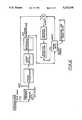
- FIG. 2illustrates the preferred method of determining the annulus transfer function when transmitting a known message
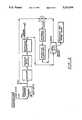
- FIG. 3illustrates the preferred method of determining the annulus transfer function when transmitting an MWD message that requires decoding at the surface.
- the signalwhen a signal is transmitted through a medium, the signal is distorted by the attenuation and phase delays of that medium.
- the phase and frequency response that characterizes the channelare referred to as the channel transfer function. If the shapes of the transmitted and received signal are known, then the transfer function of the channel can be computed. Because phase (speed of sound) and frequency response (selective energy absorption) are governed by physical properties of fluids, the transfer function is a measure of these properties. If these properties are changed by a fluid intrusion, the transfer function will change.
- the transfer function of the annulus channelis very sensitive to the presence of gas, it can be particularly useful to detect the presence of gas in the annulus. This invention is thus a method of predicting fluid influx and especially gas influx by examination of the computed annulus transfer function.
- FIG. 1a diagrammatic view of a borehole 10 is shown.
- a drillstring 12Positioned within borehole 10 is a drillstring 12.
- drilling fluidi.e. mud
- bottom hole assembly(not shown) and up through the annulus 16 defined by the space between drillstring 12 and borehole 10.
- MWD pressure pulsesare formed in the bottom hole assembly by any known pressure pulse transmitter such as described in U.S. Pat. No. 3,958,217, which is assigned to the assignee and incorporated herein by reference. These pressure pulses travel through the drilling fluid in both the drillstring interior 14 and annulus 16.
- mud column 14 and mud column 16define, respectively, a drillstring channel and an annular channel for the passage of a standpipe pulse (SPP) signal and an annulus return pulse signal (ARP).
- SPPstandpipe pulse
- ARPannulus return pulse signal
- H SDThe drillstring channel transfer function
- H SAthe annular channel transfer function
- the energy sourceWhen a downhole energy source induces energy into the mud column, such as the MWD pressure pulses identified by the arrows 18 and 20, the energy source travels to the surface through the drillstring channel 14 and the annular channel 16, and becomes distorted.
- the signal received at the surface(which includes the channel distortion) is compared with the transmitted message which will be of known shape.
- the phase and amplitide characteristics or transfer function (output signal/input signal) of the channels H SD and/or H SAcan be determined. This is accomplished by taking the Discrete Fourier Transform of the the known transmitted signal and the received signal, finding the auto and cross power spectral densities and solving for the transfer function H.sub.(S).
- This procedureis a direct method of determining the frequency characteristics of the annulus and is more sensitive to change than a time domain analysis and more accurate than indirect frequency means such as computing the ratio of the Fourier transform (power spectrum) of the standpipe pressure signal (SPP) divided by the Fourier transform (power spectrum) of the annulus return signal.
- This change in the annulus transfer functioncan be determined by (1) comparing the annulus transfer function to the transfer function in the drillstring channel; or by (2) comparing the annulus transfer function to itself over a pre-selected time history to determine changes in said annulus transfer function; or (3), comparing the annulus transfer function to a reference transfer function.
- This referencecan be a calculated (derived) function or one based on experience (knowledge based). The preferred method for making the comparison is by plotting the transfer function on timed intervals in a common "3 dimensional" or waterfall plot.
- a surface decoderis utilized to decode the standpipe signal and/ or the annulus signal message.
- a decodertypically consists of a signal amplifier, an analogue to digital converter, a digital filter and a zero crossing detection algorithm for determining ones and zeros (such as described in Modern Instrumentation Tape Recording: An Engineering Handbook, EMI Technology, Inc., p. 65 (1978) (Library of Congress Catalog Card No. 78-60084)). These devices are all common to the communications industry for decoding signals.
- the systemis employed to decode the standpipe signal and/or the annulus signal message.
- a message of known contentcan be transmitted from the bottom hole transmitter so that an accurate analysis may be made between the signal received at the surface and the transmitted signal so as to determine the transfer function.
- a frame synchronizeris employed to align the message with the known stored message. Frame synchronization is known in the art and is described, for example, on page 449 of Digital Communication by Satellite by J. J. Spilker, Jr., Prentice-Hall (1977).
- the signal received at the surfacecan be decoded and analyzed to determine the annulus transfer function.
- the FIG. 3 embodimentutilizes a method for determining the annulus transfer function which is described in detail in co-pending U.S. patent application Ser. Np. 579,706 filed Sep. 10, 1990 (now U.S. Pat. No. 5,055,837) entitled "Analysis and Identification of a Drilling Fluid Column Based on Decoding of Measurement-While-Drilling Signals" and invented by Ali Abdallah and Donald Grosso.
- This co-pending applicationis fully incorporated herein and provides a detailed description for a method of determining the annulus transfer function based entirely on information derived by the decoded annulus signal.
- the annular signalmay be so corrupt as to be of little use in reconstructing the transmitted input signal using the above-discussed method of U.S. Ser. No. 579,706.
- the input signalcan instead be reconstructed based on analysis of the output signal 18 received from the drillstring channel 14. Again, this analysis would utilize the method described in U.S. Pat. No. 5,055,937.
Landscapes
- Physics & Mathematics (AREA)
- Engineering & Computer Science (AREA)
- Life Sciences & Earth Sciences (AREA)
- Geology (AREA)
- Mining & Mineral Resources (AREA)
- Acoustics & Sound (AREA)
- Geophysics (AREA)
- Environmental & Geological Engineering (AREA)
- Fluid Mechanics (AREA)
- General Life Sciences & Earth Sciences (AREA)
- Geochemistry & Mineralogy (AREA)
- Remote Sensing (AREA)
- General Physics & Mathematics (AREA)
- Geophysics And Detection Of Objects (AREA)
Abstract
Description
Claims (14)
Priority Applications (4)
| Application Number | Priority Date | Filing Date | Title |
|---|---|---|---|
| US07/611,036US5222048A (en) | 1990-11-08 | 1990-11-08 | Method for determining borehole fluid influx |
| GB9123399AGB2249571A (en) | 1990-11-08 | 1991-11-04 | Method of detecting fluid influx in a borehole |
| NL9101858ANL9101858A (en) | 1990-11-08 | 1991-11-07 | METHOD FOR DETECTING THE INFLOW OF LIQUID OR GAS IN A BOREHOLE |
| NO91914355ANO914355L (en) | 1990-11-08 | 1991-11-07 | PROCEDURE FOR DETECTION OF INFLUENCE IN A BORROW |
Applications Claiming Priority (1)
| Application Number | Priority Date | Filing Date | Title |
|---|---|---|---|
| US07/611,036US5222048A (en) | 1990-11-08 | 1990-11-08 | Method for determining borehole fluid influx |
Publications (1)
| Publication Number | Publication Date |
|---|---|
| US5222048Atrue US5222048A (en) | 1993-06-22 |
Family
ID=24447354
Family Applications (1)
| Application Number | Title | Priority Date | Filing Date |
|---|---|---|---|
| US07/611,036Expired - Fee RelatedUS5222048A (en) | 1990-11-08 | 1990-11-08 | Method for determining borehole fluid influx |
Country Status (4)
| Country | Link |
|---|---|
| US (1) | US5222048A (en) |
| GB (1) | GB2249571A (en) |
| NL (1) | NL9101858A (en) |
| NO (1) | NO914355L (en) |
Cited By (17)
| Publication number | Priority date | Publication date | Assignee | Title |
|---|---|---|---|---|
| US5592438A (en)* | 1991-06-14 | 1997-01-07 | Baker Hughes Incorporated | Method and apparatus for communicating data in a wellbore and for detecting the influx of gas |
| US5774418A (en)* | 1994-04-28 | 1998-06-30 | Elf Aquitaine Production | Method for on-line acoustic logging in a borehole |
| US5952569A (en)* | 1996-10-21 | 1999-09-14 | Schlumberger Technology Corporation | Alarm system for wellbore site |
| WO2000000847A1 (en)* | 1998-06-29 | 2000-01-06 | Dresser Industries, Inc. | Method and apparatus for computing drill bit vibration power spectral density |
| US6196335B1 (en) | 1998-06-29 | 2001-03-06 | Dresser Industries, Inc. | Enhancement of drill bit seismics through selection of events monitored at the drill bit |
| US6310829B1 (en) | 1995-10-20 | 2001-10-30 | Baker Hughes Incorporated | Method and apparatus for improved communication in a wellbore utilizing acoustic signals |
| US20030162670A1 (en)* | 2002-02-25 | 2003-08-28 | Sweatman Ronald E. | Methods of discovering and correcting subterranean formation integrity problems during drilling |
| US6820702B2 (en) | 2002-08-27 | 2004-11-23 | Noble Drilling Services Inc. | Automated method and system for recognizing well control events |
| US6892812B2 (en) | 2002-05-21 | 2005-05-17 | Noble Drilling Services Inc. | Automated method and system for determining the state of well operations and performing process evaluation |
| US20070132606A1 (en)* | 2004-12-21 | 2007-06-14 | Baker Hughes Incorporated | Channel Equalization for Mud-Pulse Telemetry |
| CN100423799C (en)* | 1996-04-15 | 2008-10-08 | 菲兹奥控制公司 | Common therapy/data port for portable defibrillator |
| US20080285386A1 (en)* | 2005-11-10 | 2008-11-20 | Halliburton Energy Services, Inc. | Training For Directional Detection |
| US20100148787A1 (en)* | 2005-06-20 | 2010-06-17 | Marian Morys | High Frequency or Multifrequency Resistivity Tool |
| US20120006613A1 (en)* | 2010-07-06 | 2012-01-12 | Simon Tseytlin | Methods and devices for determination of gas-kick parametrs and prevention of well explosion |
| US20130168100A1 (en)* | 2011-12-28 | 2013-07-04 | Hydril Usa Manufacturing Llc | Apparatuses and Methods for Determining Wellbore Influx Condition Using Qualitative Indications |
| EP3250786A4 (en)* | 2015-01-30 | 2018-10-17 | Scientific Drilling International, Inc. | Dual mode telemetry |
| US11098577B2 (en) | 2019-06-04 | 2021-08-24 | Baker Hughes Oilfield Operations Llc | Method and apparatus to detect gas influx using mud pulse acoustic signals in a wellbore |
Families Citing this family (1)
| Publication number | Priority date | Publication date | Assignee | Title |
|---|---|---|---|---|
| CN108825156B (en)* | 2017-05-05 | 2020-08-25 | 中国石油化工股份有限公司 | Gas invasion control method for pressure control drilling |
Citations (2)
| Publication number | Priority date | Publication date | Assignee | Title |
|---|---|---|---|---|
| GB2049934A (en)* | 1979-05-23 | 1980-12-31 | Elf Aquitaine | Method and device for in situ detection of a mineral deposit fluid within a borehole |
| US5055837A (en)* | 1990-09-10 | 1991-10-08 | Teleco Oilfield Services Inc. | Analysis and identification of a drilling fluid column based on decoding of measurement-while-drilling signals |
Family Cites Families (1)
| Publication number | Priority date | Publication date | Assignee | Title |
|---|---|---|---|---|
| NO162881C (en)* | 1983-06-23 | 1990-02-28 | Teleco Oilfield Services Inc | PROCEDURE AND APPARATUS FOR DETECTION OF FLUIDUM FLOW DRAWINGS IN DRILL. |
- 1990
- 1990-11-08USUS07/611,036patent/US5222048A/ennot_activeExpired - Fee Related
- 1991
- 1991-11-04GBGB9123399Apatent/GB2249571A/ennot_activeWithdrawn
- 1991-11-07NONO91914355Apatent/NO914355L/enunknown
- 1991-11-07NLNL9101858Apatent/NL9101858A/ennot_activeApplication Discontinuation
Patent Citations (2)
| Publication number | Priority date | Publication date | Assignee | Title |
|---|---|---|---|---|
| GB2049934A (en)* | 1979-05-23 | 1980-12-31 | Elf Aquitaine | Method and device for in situ detection of a mineral deposit fluid within a borehole |
| US5055837A (en)* | 1990-09-10 | 1991-10-08 | Teleco Oilfield Services Inc. | Analysis and identification of a drilling fluid column based on decoding of measurement-while-drilling signals |
Cited By (35)
| Publication number | Priority date | Publication date | Assignee | Title |
|---|---|---|---|---|
| US5592438A (en)* | 1991-06-14 | 1997-01-07 | Baker Hughes Incorporated | Method and apparatus for communicating data in a wellbore and for detecting the influx of gas |
| GB2317955A (en)* | 1991-06-14 | 1998-04-08 | Baker Hughes Inc | Detecting gas influx into a wellbore |
| GB2317955B (en)* | 1991-06-14 | 1998-08-12 | Baker Hughes Inc | Detection of influx into a wellbore |
| US5850369A (en)* | 1991-06-14 | 1998-12-15 | Baker Hughes Incorporated | Method and apparatus for communicating data in a wellbore and for detecting the influx of gas |
| US5774418A (en)* | 1994-04-28 | 1998-06-30 | Elf Aquitaine Production | Method for on-line acoustic logging in a borehole |
| US6310829B1 (en) | 1995-10-20 | 2001-10-30 | Baker Hughes Incorporated | Method and apparatus for improved communication in a wellbore utilizing acoustic signals |
| CN100423799C (en)* | 1996-04-15 | 2008-10-08 | 菲兹奥控制公司 | Common therapy/data port for portable defibrillator |
| US5952569A (en)* | 1996-10-21 | 1999-09-14 | Schlumberger Technology Corporation | Alarm system for wellbore site |
| WO2000000847A1 (en)* | 1998-06-29 | 2000-01-06 | Dresser Industries, Inc. | Method and apparatus for computing drill bit vibration power spectral density |
| US6151554A (en)* | 1998-06-29 | 2000-11-21 | Dresser Industries, Inc. | Method and apparatus for computing drill bit vibration power spectral density |
| US6196335B1 (en) | 1998-06-29 | 2001-03-06 | Dresser Industries, Inc. | Enhancement of drill bit seismics through selection of events monitored at the drill bit |
| US20060266107A1 (en)* | 2002-02-25 | 2006-11-30 | Hulliburton Energy Services, Inc. | Methods of improving well bore pressure containment integrity |
| US7314082B2 (en) | 2002-02-25 | 2008-01-01 | Halliburton Energy Services, Inc. | Methods of improving well bore pressure containment integrity |
| US20030162670A1 (en)* | 2002-02-25 | 2003-08-28 | Sweatman Ronald E. | Methods of discovering and correcting subterranean formation integrity problems during drilling |
| US6926081B2 (en)* | 2002-02-25 | 2005-08-09 | Halliburton Energy Services, Inc. | Methods of discovering and correcting subterranean formation integrity problems during drilling |
| US20060266519A1 (en)* | 2002-02-25 | 2006-11-30 | Sweatman Ronald E | Methods of improving well bore pressure containment integrity |
| US20030181338A1 (en)* | 2002-02-25 | 2003-09-25 | Sweatman Ronald E. | Methods of improving well bore pressure containment integrity |
| US20060272860A1 (en)* | 2002-02-25 | 2006-12-07 | Halliburton Energy Services, Inc. | Methods of improving well bore pressure containment integrity |
| US7213645B2 (en) | 2002-02-25 | 2007-05-08 | Halliburton Energy Services, Inc. | Methods of improving well bore pressure containment integrity |
| US7311147B2 (en) | 2002-02-25 | 2007-12-25 | Halliburton Energy Services, Inc. | Methods of improving well bore pressure containment integrity |
| US7308936B2 (en) | 2002-02-25 | 2007-12-18 | Halliburton Energy Services, Inc. | Methods of improving well bore pressure containment integrity |
| US6892812B2 (en) | 2002-05-21 | 2005-05-17 | Noble Drilling Services Inc. | Automated method and system for determining the state of well operations and performing process evaluation |
| US6820702B2 (en) | 2002-08-27 | 2004-11-23 | Noble Drilling Services Inc. | Automated method and system for recognizing well control events |
| US7940192B2 (en)* | 2004-12-21 | 2011-05-10 | Baker Hughes Incorporated | Channel equalization for mud-pulse telemetry |
| US20070132606A1 (en)* | 2004-12-21 | 2007-06-14 | Baker Hughes Incorporated | Channel Equalization for Mud-Pulse Telemetry |
| US20100148787A1 (en)* | 2005-06-20 | 2010-06-17 | Marian Morys | High Frequency or Multifrequency Resistivity Tool |
| US8193946B2 (en)* | 2005-11-10 | 2012-06-05 | Halliburton Energy Services, Inc. | Training for directional detection |
| US20080285386A1 (en)* | 2005-11-10 | 2008-11-20 | Halliburton Energy Services, Inc. | Training For Directional Detection |
| US20120006613A1 (en)* | 2010-07-06 | 2012-01-12 | Simon Tseytlin | Methods and devices for determination of gas-kick parametrs and prevention of well explosion |
| US8235143B2 (en)* | 2010-07-06 | 2012-08-07 | Simon Tseytlin | Methods and devices for determination of gas-kick parametrs and prevention of well explosion |
| US20130168100A1 (en)* | 2011-12-28 | 2013-07-04 | Hydril Usa Manufacturing Llc | Apparatuses and Methods for Determining Wellbore Influx Condition Using Qualitative Indications |
| US9033048B2 (en)* | 2011-12-28 | 2015-05-19 | Hydril Usa Manufacturing Llc | Apparatuses and methods for determining wellbore influx condition using qualitative indications |
| EP3250786A4 (en)* | 2015-01-30 | 2018-10-17 | Scientific Drilling International, Inc. | Dual mode telemetry |
| US10349151B2 (en) | 2015-01-30 | 2019-07-09 | Scientific Drilling International, Inc. | Collaborative telemetry |
| US11098577B2 (en) | 2019-06-04 | 2021-08-24 | Baker Hughes Oilfield Operations Llc | Method and apparatus to detect gas influx using mud pulse acoustic signals in a wellbore |
Also Published As
| Publication number | Publication date |
|---|---|
| NL9101858A (en) | 1992-06-01 |
| GB2249571A (en) | 1992-05-13 |
| NO914355D0 (en) | 1991-11-07 |
| NO914355L (en) | 1992-05-11 |
| GB9123399D0 (en) | 1991-12-18 |
Similar Documents
| Publication | Publication Date | Title |
|---|---|---|
| US5222048A (en) | Method for determining borehole fluid influx | |
| US4046220A (en) | Method for distinguishing between single-phase gas and single-phase liquid leaks in well casings | |
| US5154078A (en) | Kick detection during drilling | |
| US8689904B2 (en) | Detection of gas influx into a wellbore | |
| US6585044B2 (en) | Method, system and tool for reservoir evaluation and well testing during drilling operations | |
| US4733233A (en) | Method and apparatus for borehole fluid influx detection | |
| US4297880A (en) | Downhole pressure measurements of drilling mud | |
| EP0621397B1 (en) | Method of and apparatus for detecting an influx into a well while drilling | |
| US6909667B2 (en) | Dual channel downhole telemetry | |
| US4733232A (en) | Method and apparatus for borehole fluid influx detection | |
| CA1203881A (en) | Method and apparatus for cement bond logging | |
| US20070189119A1 (en) | System and Method for Measurement While Drilling Telemetry | |
| CA1147841A (en) | Method and device for in situ detection of a mineral deposit fluid within a borehole | |
| US11231512B2 (en) | Apparatus and methods of evaluating rock properties while drilling using acoustic sensors installed in the drilling fluid circulation system of a drilling rig | |
| CA2547584C (en) | Method, system and tool for reservoir evaluation and well testing during drilling operations | |
| US20080204270A1 (en) | Measurement-while-drilling mud pulse telemetry reflection cancelation | |
| US5272680A (en) | Method of decoding MWD signals using annular pressure signals | |
| McKinley | Production logging | |
| US5777278A (en) | Multi-phase fluid flow measurement | |
| CA1218740A (en) | Method and apparatus for borehole fluid influx detection | |
| US4217659A (en) | Acoustic logging for examination of the cement bonding of well casing | |
| US5963037A (en) | Method for generating a flow profile of a wellbore using resistivity logs | |
| US4858198A (en) | Determination of formation permeability from an acoustic log | |
| USH1307H (en) | Method for continuity logging | |
| Peebler | Formation Evaluation with Logs in the Deep Anadarko Basin |
Legal Events
| Date | Code | Title | Description |
|---|---|---|---|
| AS | Assignment | Owner name:TELECO OILFIELD SERVICES INC., CONNECTICUT Free format text:ASSIGNMENT OF ASSIGNORS INTEREST.;ASSIGNORS:GROSSO, DONALD S.;ABDALLAH, ALI H.;REEL/FRAME:005504/0112 Effective date:19901108 | |
| AS | Assignment | Owner name:BAKER HUGHES DRILLING TECHNOLOGIES, INC., TEXAS Free format text:CHANGE OF NAME;ASSIGNOR:BAKER HUGHES MINING TOOLS, INC.;REEL/FRAME:006483/0256 Effective date:19930105 Owner name:BAKER HUGHES INTEQ, INC., TEXAS Free format text:CHANGE OF NAME;ASSIGNOR:BAKER HUGHES PRODUCTION TOOLS, INC.;REEL/FRAME:006483/0264 Effective date:19930310 Owner name:EASTMAN TELECO COMPANY, TEXAS Free format text:MERGER;ASSIGNOR:TELECO OILFIELD SERVICES, INC.;REEL/FRAME:006483/0244 Effective date:19920701 Owner name:BAKER HUGHES INCORPORATED, TEXAS Free format text:ASSIGNMENT OF ASSIGNORS INTEREST.;ASSIGNOR:BAKER HUGHES INTEQ, INC.;REEL/FRAME:006483/0267 Effective date:19930401 Owner name:BAKER HUGHES MINING TOOLS, INC., TEXAS Free format text:MERGER;ASSIGNOR:EASTMAN TELECO COMPANY;REEL/FRAME:006483/0250 Effective date:19930101 Owner name:BAKER HUGHES PRODUCTION TOOLS, INC., TEXAS Free format text:MERGER;ASSIGNOR:BAKER HUGHES DRILLING TECHNOLOGIES, INC.;REEL/FRAME:006483/0260 Effective date:19930315 | |
| REMI | Maintenance fee reminder mailed | ||
| LAPS | Lapse for failure to pay maintenance fees | ||
| FP | Lapsed due to failure to pay maintenance fee | Effective date:19970625 | |
| STCH | Information on status: patent discontinuation | Free format text:PATENT EXPIRED DUE TO NONPAYMENT OF MAINTENANCE FEES UNDER 37 CFR 1.362 |