US5219349A - Spinal fixator reduction frame - Google Patents
Spinal fixator reduction frameDownload PDFInfo
- Publication number
- US5219349A US5219349AUS07/657,024US65702491AUS5219349AUS 5219349 AUS5219349 AUS 5219349AUS 65702491 AUS65702491 AUS 65702491AUS 5219349 AUS5219349 AUS 5219349A
- Authority
- US
- United States
- Prior art keywords
- members
- rigid
- extending
- dorsally
- sleeve
- Prior art date
- Legal status (The legal status is an assumption and is not a legal conclusion. Google has not performed a legal analysis and makes no representation as to the accuracy of the status listed.)
- Expired - Fee Related
Links
Images


Classifications
- A—HUMAN NECESSITIES
- A61—MEDICAL OR VETERINARY SCIENCE; HYGIENE
- A61B—DIAGNOSIS; SURGERY; IDENTIFICATION
- A61B17/00—Surgical instruments, devices or methods
- A61B17/56—Surgical instruments or methods for treatment of bones or joints; Devices specially adapted therefor
- A61B17/58—Surgical instruments or methods for treatment of bones or joints; Devices specially adapted therefor for osteosynthesis, e.g. bone plates, screws or setting implements
- A61B17/68—Internal fixation devices, including fasteners and spinal fixators, even if a part thereof projects from the skin
- A61B17/70—Spinal positioners or stabilisers, e.g. stabilisers comprising fluid filler in an implant
- A61B17/7074—Tools specially adapted for spinal fixation operations other than for bone removal or filler handling
- A61B17/7076—Tools specially adapted for spinal fixation operations other than for bone removal or filler handling for driving, positioning or assembling spinal clamps or bone anchors specially adapted for spinal fixation
- A61B17/7077—Tools specially adapted for spinal fixation operations other than for bone removal or filler handling for driving, positioning or assembling spinal clamps or bone anchors specially adapted for spinal fixation for moving bone anchors attached to vertebrae, thereby displacing the vertebrae
Definitions
- the present inventionrelates to devices for use in spinal fixation operations and more particularly to a device for controlled alignment of a fractured spine in conjunction with the Vermont Spinal Fixator implant.
- FIG. 1illustrates one half of a Vermont Spinal Fixator device 10 in place on a spine, the same components are also used on the opposite side of the spine and are not shown.
- the fixator deviceis designed to rigidly fix together two spinal vertebrae surrounding a fractured vertebrae and, thus, fuse the spine around the fractured vertebrae.
- the Vermont Spinal Fixatoris disclosed in detail in Krag et al., An Internal Fixator for Posterior Application to Short Segments of the Thoracic, Lumbar, or Lumbosacral Spine, Clinical Orthopaedics and Related Research, 203: 75-98 (February 1986).
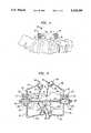
- each vertebraeIn order to implant the fixator device 10, holes are drilled in the appropriate vertebrae through the pedicle on either side of each vertebrae. After the holes are drilled, pedicle screws 12 are screwed into place using a shaft handle 14 which is attached to flats 16 provided on the top of each screw 12. The shaft handles 14 are best seen in FIG. 2. Once the pedicle screws 12 are in place, each one has an articulating clamp 18 attached to it by means of a clamp bolt 20.
- Clamp bolt 20is placed through clamp 18 and loosely threaded into the head of pedicle screw 12.
- the clamp bolts 20are left loose until realignment of the vertebrae by the reduction frame has been completed.
- Shaft handles 14remain attached to the tops of the pedicle screws 12.
- the shaft handlesmay be provided with removable grips which are not shown in FIG. 2.
- fixator device 10As a result of various spinal disorders of the type which the fixator device 10 is intended to remedy, such as trauma, one vertebra is displaced to an abnormal position relative to an adjacent vertebra. For this reason the surgeon must manipulate the vertebrae back into normal alignment before the clamp bolts 20 are finally tightened and the spine is rigidly fixed in position.
- U.S. Pat. No. 3,865,105 to Lodediscloses a device for exerting force on and fixing the spinal column.
- the Lode deviceappears to be designed primarily for the correction of scoliosis.
- the arrangement of this devicerenders it impractical for use in producing realignment of vertebrae affected by fractures and dislocations.
- the amount of control providedis limited as it is much less of a factor in applications such as straightening an unfractured spine contemplated by the Lode device.
- the three point attachment directly to the transverse process or spinous processwould obstruct the surgical area such that a spinal fixator device being implanted could not be easily accessed.
- Another object of the present inventionis to provide such a device which may be attached to the spine in any orientation prior to alignment.
- Another object of the present inventionis to provide a device for alignment of the spine which does not block access to the surgical area in order to allow for access to the fixator device being implanted.
- Yet another object of the present inventionis to provide a versatile device which may be used with hand application of forces and varying degrees of mechanical assistance.
- a further object of the present inventionis to provide a device for alignment of a spine which is capable of controlling all modes of motion, that is, flexion/extension, lateral bending, axial rotation, distraction/compression, anterior/posterior shear, and lateral shear.
- a further object of the present inventionis to provide a device for alignment of a spine which includes a mechanical means for producing the motions of flexion/extension, distraction/compression, and anterior/posterior shear.
- a reduction framewhich is secured by shaft clamp assemblies to shaft handles extending from the pedicle screws of a fixator device.
- the shaft clamp assembliesare provided with four degrees of freedom (3 rotational and 1 translational).
- the shaft clamp assembliessecure two T-handles to the shaft handles. Each T-handle may be grasped by hand to manually apply forces to the spine, or the two T-handles may be joined by a mechanically adjustable lower-rod assembly.
- the lower-rod assemblyprovides a mechanism to produce controlled distraction/compression and provides a fulcrum about which manually-applied force to the T-handles will produce flexion/extension.
- the lower-rod assemblyis joined to each T-handle by means of a lower-rod clamp, which is provided with 4 or 5 degrees of freedom (2 or 3 rotational and 2 translational).
- Each T-handleis provided with power screw threads to allow for precise anterior/posterior translational control.
- the shaft clamps and lower-rod clampsare provided with taper fit joints to allow for infinite rotational adjustment and fixture.
- an upper-rod assemblymay also be attached to the T-handles as desired. By rotating either nut on the upper-rod assembly, the distance between the upper ends of the T-handles may be increased or decreased. This will cause the T-handle to rotate about its lower-rod clamp, thereby rotating the vertebra to produce the desired alignment. Finger grips are provided on the upper-rod assembly to allow the surgeon to easily use one hand to either apply or monitor the force acting along the upper-rod.
- the reduction frame according to the present inventionallows for the controlled application of forces to produce motion of one vertebra relative to another, by means of attachment of the device to the pedicles.
- the T-handlesfunction as handles to allow manipulation of the spine with an even distribution of force between opposite pedicles, in order to prevent the application of excessive load to either pedicle.
- the power screw adjustmentsallow for a fine and gradual application of force to produce the desired vertebral movements.
- the multiple degrees of freedom of the clampsallow for assembly of the reduction frame in any orientation and for forces to be applied in virtually any direction.
- the T-handlesare offset from the surgical area by hinged extensions to allow for easy access to the device assembly device after alignment has been achieved, in order to allow for final fixation and tightening of the clamp bolts.
- FIG. 1is a side view of a spine with a Vermont Spinal Fixator implanted thereon;
- FIG. 2is a side elevation of the reduction frame according to the present invention.
- FIG. 3is a section view through line 3--3 of FIG. 2;
- FIG. 4is a partial section view of a shaft clamp of the present invention.
- FIG. 5is a perspective view of a T-handle of the present invention.
- FIG. 6is a perspective view of the lower-rod assembly of the present invention.
- the reduction frame 50comprises three basic assemblies: T-handles 100, of which there are two; lower-rod assembly 200; and upper-rod assembly 300.
- T-handle 100is shown separately in FIG. 5 and lower-rod assembly 200 is shown separately in FIG. 6.
- the upper and lower-rod assembliesare not necessarily required for the proper functioning of the invention.
- the T-handles 100may be used alone, with the lower-rod assembly 200 only, or with the upper and lower-rod assemblies 300, 200.
- Each T-handle 100has a dorsally extending threaded leg 110 and two laterally extending arms 112.
- the dorsal directionis indicated by arrow 30 in FIG. 2 and the lateral directions by arrow 32 in FIG. 3.
- Threaded leg 110is provided with power screw threads 114.
- a sleeve 116is placed over the dorsally extending leg 110 and its dorsal-ventral location is controlled by thumb nuts 118.
- the leg 110may be provided with a flat side 120 cooperating with a complimentary flat inside sleeve 116 to prevent undesired rotation of the sleeve 116.
- Disposed on sleeve 116are female clamping collar 117 and eye socket 119.
- Female clamping collar 117is rotatable around sleeve 116. Clamping collar 117 may be fixed against rotation by tightening screw 115, shown best in FIG. 3. The function of the sleeve 116 is related to the lower-rod assembly 200 and therefore will be discussed below in conjunction with that component. Eye socket 119 receives ball nuts 316 of upper-rod assembly 300.
- each laterally extending arm 112Disposed adjacent the outer extremity of each laterally extending arm 112 is a shaft clamp 122.
- the shaft clampsprovide a positive linkage between the T-handles 100 and the shaft handles 14 attached to the pedicle screws 12.
- the orientation of the shaft handles 14 extending from the pedicleis dependent upon the orientation of the vertebrae prior to alignment. Therefore, it must be possible to attach the T-handles 100 to the shaft handles 14 in any orientation. For this reason the shaft clamps 122 provide for three rotational degrees of freedom and one translational degree of freedom along shaft handles 14.
- the laterally extending arms 112 of the T-handles 100have hinged extensions 136.
- the shaft clamps 122are disposed at the end of the hinged extensions 136 of the laterally extending arms 112.
- Shaft clamps 122shown in detail in FIG. 4, comprise two U-shaped collars 124, 126 which are clamped together by a bolt 128 and retained by internal threads 129 in collar 126.
- a retaining ring 127may be provided on bolt 128 to prevent the bolt from backing out of collar 126.
- Internal taper fit joint 130is provided between the two collars 124, 126 of a shaft clamp 122 in order to allow for infinite positioning and positive fixation.
- collar 126is formed with frustoconical projection 132 and collar 126 with a mating frustoconical recess 134 of slightly smaller dimension. Tightening of bolt 128 increases the interference fit and provides positive fixation. Loosening of bolt 128 allows slippage between the mating frustoconical parts 132, 134 which may then be placed in an infinite number of positions because the mating surfaces are smooth.
- the T-handles 100 of the present inventionprovide a positive linkage between the two pedicles to which it is attached.
- the linkageensures that force applied is evenly distributed to the two pedicles, thereby decreasing the likelihood of damage to any one pedicle.
- Lower-rod assembly 200shown separately in FIG. 6, comprises a rigid lower threaded rod 210 of sufficient length to extend between and beyond the dorsally extending legs 110 of the T-handles 100 when they are installed on the spine in their usual configuration. Power screw threads 212 are also used for threaded rod 210. Placed over and slidable on threaded rod 210 are lower-rod sleeves 214 and 215. Translation and fixation of the lower-rod sleeves on threaded rod 210 are controlled by thumb nuts 216. Threaded rod 210 is also preferably provided with a flat side 218 engaging a complimentary flat inside the lower-rod sleeves to prevent undesired rotation.
- Lower-rod sleeve 214is linked to one of the T-handle sleeves 116 by male clamping collar 220 which cooperates with an associated female clamping collar 117.
- Female clamping collar 117has a frustoconical recess 117a which mates with a frustoconical projection of male clamping collar 220 to provide a frustoconical taper fit joint similar to taper fit joints 130 in shaft clamps 122. Tightening of the taper fit joint between collars 117 and 220 is accomplished by bolt 221.
- Lower-rod sleeve 215is linked to the opposite T-handle 100 by male member 224 which is formed integrally with sleeve 215.
- Male member 224also has a frustoconical projection which is received in frustoconical recess 117a of the associated female clamping collar 117.
- Bolt 226controls the tightening of the taper fit joint formed between male member 224 and female clamping collar 117.
- lower-rod assembly 200effectively provides for rigid connection between T-handles 100 and lower-rod assembly 200, while providing five degrees of freedom for adjustment: two rotational degrees of freedom provided by clamping collars 117 around sleeves 116 and around their taper fit joints with clamping collars 220, 224; one rotational degree of freedom provided by male clamping collar 220 and sleeve 214; and two translational degrees of freedom provided by the movement of T-handle sleeves 116 or threaded leg 110 and lower-rod sleeves 214 and 215 on threaded rod 210.
- the surgeonmay execute any of the common movements of the spine (flexion, extension, distraction, compression or anterior/posterior shear) with a high degree of mechanical control.
- all rotational degrees of freedommay be fixed and only translation along lower-rod assembly 200 utilized. This would provide a pure distraction-compression movement. The movement can be controlled with great precision by the use of thumb nuts 216.
- all degrees of freedommay be fixed except for one rotational degree of freedom between T-handles 100 and lower-rod assembly 200 about a transverse or side-to-side axis. This would provide a pure flexion-extension movement by force applied manually to the dorsally extending legs 110 of the T-handles 100. It should be readily appreciated that by employing the various adjustments available with the reduction frame according to the present invention, an infinite variety of controlled compound movements may be devised as required to align the fractured spine.
- the upper-rod assembly 300comprises a threaded rod 310 of about the same length as the lower threaded rod 210, although it may be relatively smaller in diameter because it experiences only tensile and compressive forces.
- the threads 312 on the upper-rod assembly 300are again preferably power screw threads.
- the upper-rod 310runs through eye sockets 119 on T-handle sleeves 116 and ball nuts 316 bear against the eyes 119 to apply force to the T-handles 100.
- Finger grips 318may be provided on the upper-rod 310 to provide a means for the surgeon to feel the amount of force required for a particular movement.
- T-handle sleeve 116places T-handle sleeve 116 in his palm and then wraps his fingers around finger grip 318, whereby a squeezing motion gradually applies an inward force to the ends of the T-handles 100 (moving the handles together).
- the use of ball nuts 316allows for fine mechanical control of movements such as the flexion-extension movement described in the preceding paragraph.
Landscapes
- Health & Medical Sciences (AREA)
- Neurology (AREA)
- Orthopedic Medicine & Surgery (AREA)
- Life Sciences & Earth Sciences (AREA)
- Surgery (AREA)
- Heart & Thoracic Surgery (AREA)
- Engineering & Computer Science (AREA)
- Biomedical Technology (AREA)
- Nuclear Medicine, Radiotherapy & Molecular Imaging (AREA)
- Medical Informatics (AREA)
- Molecular Biology (AREA)
- Animal Behavior & Ethology (AREA)
- General Health & Medical Sciences (AREA)
- Public Health (AREA)
- Veterinary Medicine (AREA)
- Surgical Instruments (AREA)
- Prostheses (AREA)
Abstract
Description
Claims (21)
Priority Applications (4)
| Application Number | Priority Date | Filing Date | Title |
|---|---|---|---|
| US07/657,024US5219349A (en) | 1991-02-15 | 1991-02-15 | Spinal fixator reduction frame |
| CA002058746ACA2058746A1 (en) | 1991-02-15 | 1992-01-03 | Spinal fixator reduction frame |
| EP19920100619EP0499037A3 (en) | 1991-02-15 | 1992-01-15 | Spinal fixator reduction frame |
| JP4028309AJP2573769B2 (en) | 1991-02-15 | 1992-02-14 | Reduction frame for spine fixation |
Applications Claiming Priority (1)
| Application Number | Priority Date | Filing Date | Title |
|---|---|---|---|
| US07/657,024US5219349A (en) | 1991-02-15 | 1991-02-15 | Spinal fixator reduction frame |
Publications (1)
| Publication Number | Publication Date |
|---|---|
| US5219349Atrue US5219349A (en) | 1993-06-15 |
Family
ID=24635544
Family Applications (1)
| Application Number | Title | Priority Date | Filing Date |
|---|---|---|---|
| US07/657,024Expired - Fee RelatedUS5219349A (en) | 1991-02-15 | 1991-02-15 | Spinal fixator reduction frame |
Country Status (4)
| Country | Link |
|---|---|
| US (1) | US5219349A (en) |
| EP (1) | EP0499037A3 (en) |
| JP (1) | JP2573769B2 (en) |
| CA (1) | CA2058746A1 (en) |
Cited By (123)
| Publication number | Priority date | Publication date | Assignee | Title |
|---|---|---|---|---|
| US5306275A (en)* | 1992-12-31 | 1994-04-26 | Bryan Donald W | Lumbar spine fixation apparatus and method |
| US5478340A (en)* | 1992-01-31 | 1995-12-26 | Kluger; Patrick | Vertebral column implant and repositioning instrument |
| US5498262A (en)* | 1992-12-31 | 1996-03-12 | Bryan; Donald W. | Spinal fixation apparatus and method |
| US5538215A (en)* | 1994-11-15 | 1996-07-23 | Midmark Corporation | Siderail socket |
| WO1996026679A1 (en)* | 1995-03-01 | 1996-09-06 | Taylor Harold S | Geared external fixator |
| US5595563A (en)* | 1995-09-05 | 1997-01-21 | Moisdon; Roger G. F. | Method and apparatus for maintaining the position of body parts |
| US5645079A (en)* | 1994-12-02 | 1997-07-08 | Zahiri; Hormoz | Apparatus for mechanically holding, maneuvering and maintaining a body part of a patient during orthopedic surgery |
| US5653707A (en)* | 1994-11-01 | 1997-08-05 | Smith & Nephew Richards, Inc. | External skeletal fixation system with improved bar-to-bar connector |
| US5672175A (en)* | 1993-08-27 | 1997-09-30 | Martin; Jean Raymond | Dynamic implanted spinal orthosis and operative procedure for fitting |
| US5683389A (en)* | 1994-12-05 | 1997-11-04 | Smith & Nephew, Inc. | External fixator for distal radius fractures |
| US5704937A (en)* | 1993-08-27 | 1998-01-06 | Paulette Fairant | Operative equipment for fixing spinal instrumentation |
| US5733284A (en)* | 1993-08-27 | 1998-03-31 | Paulette Fairant | Device for anchoring spinal instrumentation on a vertebra |
| US5769820A (en)* | 1993-10-22 | 1998-06-23 | David H. Rammler | Abdominal lifting apparatus and methods for trocar surgical procedure |
| US5797910A (en)* | 1993-08-27 | 1998-08-25 | Paulette Fairant | Operative equipment for correcting a spinal deformity |
| WO1999022661A1 (en) | 1997-11-04 | 1999-05-14 | Smith & Nephew, Inc. | External fixator for distal radius fractures |
| US6123707A (en)* | 1999-01-13 | 2000-09-26 | Spinal Concepts, Inc. | Reduction instrument |
| US6162223A (en)* | 1999-04-09 | 2000-12-19 | Smith & Nephew, Inc. | Dynamic wrist fixation apparatus for early joint motion in distal radius fractures |
| US6296647B1 (en)* | 1998-08-07 | 2001-10-02 | Stryker Trauma Gmbh | Instrument for the positioning of an implant in the human spine |
| DE10028181A1 (en)* | 2000-06-09 | 2001-12-20 | Biomet Merck Deutschland Gmbh | Repositioning instrument; has at least two holders for two pedicle screws, which are joined by U-shaped connector that can be adjusted in position and in spacing of U-shape arms |
| US6409729B1 (en) | 1998-05-19 | 2002-06-25 | Synthes (Usa) | Clamp assembly for an external fixation system |
| US20030060823A1 (en)* | 2001-09-24 | 2003-03-27 | Bryan Donald W. | Pedicle screw spinal fixation device |
| US6565568B1 (en) | 2000-09-28 | 2003-05-20 | Chaim Rogozinski | Apparatus and method for the manipulation of the spine and sacrum in the treatment of spondylolisthesis |
| US6565564B2 (en) | 2000-12-14 | 2003-05-20 | Synthes U.S.A. | Multi-pin clamp and rod attachment |
| US6746449B2 (en) | 2001-09-12 | 2004-06-08 | Spinal Concepts, Inc. | Spinal rod translation instrument |
| US20040138659A1 (en)* | 2003-01-10 | 2004-07-15 | Ed Austin | External fixation apparatus and method |
| US20050021040A1 (en)* | 2003-07-21 | 2005-01-27 | Rudolf Bertagnoli | Vertebral retainer-distracter and method of using same |
| US20050119656A1 (en)* | 2002-02-04 | 2005-06-02 | Joseph Ferrante | External fixation system |
| US20050143737A1 (en)* | 2003-12-31 | 2005-06-30 | John Pafford | Dynamic spinal stabilization system |
| US20050143823A1 (en)* | 2003-12-31 | 2005-06-30 | Boyd Lawrence M. | Dynamic spinal stabilization system |
| US20050245939A1 (en)* | 2002-06-14 | 2005-11-03 | Joseph Ferrante | Device and methods for placing external fixation elements |
| US6964665B2 (en) | 2000-12-29 | 2005-11-15 | Thomas James C | Vertebral alignment system |
| US20060025769A1 (en)* | 2004-07-30 | 2006-02-02 | Dick Jeffrey C | Surgical devices and methods for vertebral shifting utilizing spinal fixation systems |
| US20060036246A1 (en)* | 2004-08-03 | 2006-02-16 | Carl Allen L | Device and method for correcting a spinal deformity |
| US20060036245A1 (en)* | 2004-08-04 | 2006-02-16 | Leslie Stern | Surgical base unit and retractor support mechanism |
| US20060079908A1 (en)* | 2004-09-29 | 2006-04-13 | The Cleveland Clinic Foundation | Minimally invasive method and apparatus for placing facet screws and fusing adjacent vertebrae |
| US7032871B1 (en)* | 2003-03-13 | 2006-04-25 | Akrep Michael J | Linear adjustment device and linear adjustment system incorporating the device and method of use |
| US7048735B2 (en) | 2002-02-04 | 2006-05-23 | Smith & Nephew | External fixation system |
| US20060200131A1 (en)* | 2005-03-04 | 2006-09-07 | Depuy Spine Sarl | Constrained motion bone screw assembly |
| US20060200132A1 (en)* | 2005-03-04 | 2006-09-07 | Chao Nam T | Instruments and methods for manipulating a vertebra |
| US20060217735A1 (en)* | 2005-03-11 | 2006-09-28 | Macdonald Joel | Bone repair device and method |
| USRE39325E1 (en) | 1992-12-31 | 2006-10-03 | Bryan Donald W | Spinal fixation apparatus and method |
| US20060271050A1 (en)* | 2005-03-30 | 2006-11-30 | Gabriel Piza Vallespir | Instrumentation and methods for reducing spinal deformities |
| US20070049936A1 (en)* | 2005-08-26 | 2007-03-01 | Dennis Colleran | Alignment instrument for dynamic spinal stabilization systems |
| US20070127626A1 (en)* | 2005-11-23 | 2007-06-07 | Marino James F | Method and system for guidance system positioner |
| US20070191831A1 (en)* | 2006-01-26 | 2007-08-16 | Depuy Spine, Inc. | System and method for cooling a spinal correction device comprising a shape memory material for corrective spinal surgery |
| US20070191833A1 (en)* | 2006-01-27 | 2007-08-16 | Sdgi Holdings, Inc. | Spinal implants including a sensor and methods of use |
| US20070213715A1 (en)* | 2006-02-09 | 2007-09-13 | Sdgi Holdings, Inc. | Spinal derotation instruments and methods |
| US20080269805A1 (en)* | 2007-04-25 | 2008-10-30 | Warsaw Orthopedic, Inc. | Methods for correcting spinal deformities |
| US20080269810A1 (en)* | 2007-04-12 | 2008-10-30 | Texas Scottish Rite Hospital For Children | Orthopedic Fastener for Stabilization and Fixation |
| US20090088803A1 (en)* | 2007-10-01 | 2009-04-02 | Warsaw Orthopedic, Inc. | Flexible members for correcting spinal deformities |
| US20090198273A1 (en)* | 2008-02-02 | 2009-08-06 | Texas Scottish Rite Hospital For Children | Pedicle Screw |
| US20090198279A1 (en)* | 2008-02-02 | 2009-08-06 | Texas Scottish Rite Hospital For Children | Spinal Rod Link Reducer |
| US20090216237A1 (en)* | 2005-07-01 | 2009-08-27 | Spinevision | Instrument for Moving a Vertebra |
| US20090228053A1 (en)* | 2008-03-10 | 2009-09-10 | Eric Kolb | Derotation instrument with reduction functionality |
| US20090312804A1 (en)* | 2008-06-17 | 2009-12-17 | Thomas Gamache | Adjustable implant assembly |
| US20100076447A1 (en)* | 2004-08-04 | 2010-03-25 | Leslie Stern | Surgical Base Unit and Retractor Support Mechanism |
| US7722651B2 (en) | 2005-10-21 | 2010-05-25 | Depuy Spine, Inc. | Adjustable bone screw assembly |
| US20110087293A1 (en)* | 2009-10-14 | 2011-04-14 | Ebi, Llc | Deformable Device For Minimally Invasive Fixation |
| US20110190820A1 (en)* | 2008-05-28 | 2011-08-04 | Erik Johansson | Displacement Device, Use and System Therefore |
| US8038699B2 (en) | 2006-09-26 | 2011-10-18 | Ebi, Llc | Percutaneous instrument assembly |
| US8114158B2 (en) | 2004-08-03 | 2012-02-14 | Kspine, Inc. | Facet device and method |
| US8162979B2 (en) | 2007-06-06 | 2012-04-24 | K Spine, Inc. | Medical device and method to correct deformity |
| US8162952B2 (en) | 2006-09-26 | 2012-04-24 | Ebi, Llc | Percutaneous instrument assembly |
| US20120123301A1 (en)* | 2010-11-12 | 2012-05-17 | Connor Robert A | Spinal motion measurement device |
| US20120143191A1 (en)* | 2006-12-20 | 2012-06-07 | Brian Foote | Joint fixator |
| US20120197297A1 (en)* | 2010-09-09 | 2012-08-02 | Zoher Bootwala | Vertebral adjustment systems for spine alignment |
| CN102727295A (en)* | 2012-07-07 | 2012-10-17 | 苏州市康力骨科器械有限公司 | Minimally invasive opening pressurizer |
| US8357183B2 (en) | 2009-03-26 | 2013-01-22 | Kspine, Inc. | Semi-constrained anchoring system |
| US8388253B2 (en) | 2010-10-30 | 2013-03-05 | Kenneth Rae McCLELLAND | Linkage coupling apparatus |
| US8414614B2 (en) | 2005-10-22 | 2013-04-09 | Depuy International Ltd | Implant kit for supporting a spinal column |
| US8425563B2 (en) | 2006-01-13 | 2013-04-23 | Depuy International Ltd. | Spinal rod support kit |
| US8430914B2 (en) | 2007-10-24 | 2013-04-30 | Depuy Spine, Inc. | Assembly for orthopaedic surgery |
| US8523858B2 (en) | 2005-06-21 | 2013-09-03 | DePuy Synthes Products, LLC | Adjustable fixation clamp and method |
| US8709015B2 (en) | 2008-03-10 | 2014-04-29 | DePuy Synthes Products, LLC | Bilateral vertebral body derotation system |
| US8758343B2 (en) | 2005-04-27 | 2014-06-24 | DePuy Synthes Products, LLC | Bone fixation apparatus |
| US8828058B2 (en) | 2008-11-11 | 2014-09-09 | Kspine, Inc. | Growth directed vertebral fixation system with distractible connector(s) and apical control |
| US8920472B2 (en) | 2011-11-16 | 2014-12-30 | Kspine, Inc. | Spinal correction and secondary stabilization |
| US8992536B2 (en) | 2010-06-24 | 2015-03-31 | Warsaw Orthopedic, Inc. | Coplanar deformity correction system |
| US9011450B2 (en) | 2012-08-08 | 2015-04-21 | DePuy Synthes Products, LLC | Surgical instrument |
| US9101416B2 (en) | 2003-01-24 | 2015-08-11 | DePuy Synthes Products, Inc. | Spinal rod approximator |
| US9168071B2 (en) | 2009-09-15 | 2015-10-27 | K2M, Inc. | Growth modulation system |
| US9179947B2 (en) | 2012-07-03 | 2015-11-10 | Tedan Surgical Innovations, Llc | Locking distractor with two-start distraction screw |
| US9179957B2 (en) | 2012-08-09 | 2015-11-10 | Spinecraft, LLC | Systems, assemblies and methods for spinal derotation |
| US9314274B2 (en) | 2011-05-27 | 2016-04-19 | DePuy Synthes Products, Inc. | Minimally invasive spinal fixation system including vertebral alignment features |
| US9333009B2 (en) | 2011-06-03 | 2016-05-10 | K2M, Inc. | Spinal correction system actuators |
| US9345517B2 (en) | 2008-02-02 | 2016-05-24 | Globus Medical, Inc. | Pedicle screw having a removable rod coupling |
| US9402660B2 (en) | 2013-09-05 | 2016-08-02 | Warsaw Orthopedic, Inc. | Surgical instrument and method |
| US9402663B2 (en) | 2010-04-23 | 2016-08-02 | DePuy Synthes Products, Inc. | Minimally invasive instrument set, devices and related methods |
| US9408716B1 (en) | 2013-12-06 | 2016-08-09 | Stryker European Holdings I, Llc | Percutaneous posterior spinal fusion implant construction and method |
| US9451987B2 (en) | 2011-11-16 | 2016-09-27 | K2M, Inc. | System and method for spinal correction |
| US9468468B2 (en) | 2011-11-16 | 2016-10-18 | K2M, Inc. | Transverse connector for spinal stabilization system |
| US9468469B2 (en) | 2011-11-16 | 2016-10-18 | K2M, Inc. | Transverse coupler adjuster spinal correction systems and methods |
| US9468471B2 (en) | 2013-09-17 | 2016-10-18 | K2M, Inc. | Transverse coupler adjuster spinal correction systems and methods |
| US9498262B2 (en) | 2006-04-11 | 2016-11-22 | DePuy Synthes Products, Inc. | Minimally invasive fixation system |
| US20160354073A1 (en)* | 2015-06-04 | 2016-12-08 | Minimal Invasive Technologies (Pty) Ltd. | Pedicle mountable retractor system |
| US20170020537A1 (en)* | 2015-07-20 | 2017-01-26 | Robert TUTEN | Surgical jig assembly for use in the manipulation and fixation of bony structures |
| US9554832B2 (en) | 2007-05-18 | 2017-01-31 | Stryker European Holdings I, Llc | Apparatus and method for direct vertebral rotation |
| US9579126B2 (en) | 2008-02-02 | 2017-02-28 | Globus Medical, Inc. | Spinal rod link reducer |
| US9622795B2 (en) | 2013-12-13 | 2017-04-18 | Stryker European Holdings I, Llc | Tissue retraction and vertebral displacement devices, systems, and methods for posterior spinal fusion |
| US9744050B1 (en) | 2013-12-06 | 2017-08-29 | Stryker European Holdings I, Llc | Compression and distraction system for percutaneous posterior spinal fusion |
| US9763702B2 (en) | 2012-11-16 | 2017-09-19 | DePuy Synthes Products, Inc. | Bone fixation assembly |
| US9770272B2 (en) | 2012-12-12 | 2017-09-26 | Wright Medical Technology, Inc. | Orthopedic compression/distraction device |
| US20170311987A1 (en)* | 2016-04-27 | 2017-11-02 | Warsaw Orthopedic, Inc | Spinal correction system and method |
| US9808281B2 (en) | 2009-05-20 | 2017-11-07 | DePuy Synthes Products, Inc. | Patient-mounted retraction |
| US9861393B2 (en) | 2012-08-09 | 2018-01-09 | Spinecraft, LLC | Systems, assemblies and methods for spinal derotation |
| US9907582B1 (en) | 2011-04-25 | 2018-03-06 | Nuvasive, Inc. | Minimally invasive spinal fixation system and related methods |
| US20180153585A1 (en)* | 2016-12-06 | 2018-06-07 | Marc J. LEVINE | Retractor/compression/distraction system |
| US20180228520A1 (en)* | 2016-04-27 | 2018-08-16 | Warsaw Orthopedic, Inc. | Spinal correction system and method |
| US10098665B2 (en) | 2012-08-01 | 2018-10-16 | DePuy Synthes Products, Inc. | Spine derotation system |
| US10159579B1 (en) | 2013-12-06 | 2018-12-25 | Stryker European Holdings I, Llc | Tubular instruments for percutaneous posterior spinal fusion systems and methods |
| US10194960B1 (en) | 2015-12-03 | 2019-02-05 | Nuvasive, Inc. | Spinal compression instrument and related methods |
| US10194958B2 (en) | 2016-04-27 | 2019-02-05 | Warsaw Othopedic, Inc. | Spinal correction system and method |
| USD842479S1 (en) | 2016-04-27 | 2019-03-05 | Warsaw Orthopedic, Inc. | Spinal implant |
| RU190701U1 (en)* | 2019-02-22 | 2019-07-09 | Федеральное государственное бюджетное образовательное учреждение высшего образования "Казанский Государственный медицинский университет" Министерства здравоохранения Российской Федерации | DRAIN FILLER |
| WO2019232057A1 (en) | 2018-05-30 | 2019-12-05 | Acumed Llc | Distraction/compression apparatus and method for bone |
| US10499897B2 (en) | 2017-03-06 | 2019-12-10 | Thompson Surgical Instruments, Inc. | Distractor with bidirectional ratchet |
| US10543022B2 (en) | 2016-10-11 | 2020-01-28 | Warsaw Orthopedic, Inc. | Spinal implant system and method |
| US10646261B2 (en) | 2018-07-24 | 2020-05-12 | Warsaw Orthopedic, Inc. | Multi-purpose screwdriver and method of use |
| US10702311B2 (en) | 2011-11-16 | 2020-07-07 | K2M, Inc. | Spinal correction and secondary stabilization |
| US10952714B1 (en) | 2017-07-14 | 2021-03-23 | OrtoWay AB | Apparatus, methods and systems for spine surgery |
| US20220323114A1 (en)* | 2021-04-07 | 2022-10-13 | Ernest Wright | Spinal stabilization apparatus for the detection and prevention of a loss of robotic accuracy and method thereof |
| US11517351B2 (en)* | 2018-06-04 | 2022-12-06 | Daniel Chan | External fixation devices for posterior pelvic compression and methods of use |
| RU2843631C2 (en)* | 2024-08-05 | 2025-07-17 | Общество с ограниченной ответственностью "КОНМЕТ" | Device for surgical correction of spinal deformities |
Families Citing this family (6)
| Publication number | Priority date | Publication date | Assignee | Title |
|---|---|---|---|---|
| DE19516310A1 (en)* | 1995-05-04 | 1996-11-07 | Man Ceramics Gmbh | Supports for positioning at least two bone sections |
| AU2003295934B2 (en)* | 2002-11-23 | 2009-02-26 | Frey, George A. | Distraction and retraction system for spinal surgery |
| CN101612054B (en)* | 2009-07-24 | 2011-01-05 | 王铁铸 | External-distraction pedicle screw-rod bracket of vertebral body |
| EP2705799B1 (en)* | 2012-09-06 | 2015-05-13 | Medacta International S.A. | Surgical device for minimally invasive spinal fusion and surgical system comprising the same |
| EP3352683B1 (en)* | 2015-09-24 | 2024-02-07 | Swiss Medical Instruments AG | Distractor device |
| GB2571913B (en)* | 2018-02-12 | 2022-08-10 | Papadionysiou Filippos | Repositioning jig |
Citations (15)
| Publication number | Priority date | Publication date | Assignee | Title |
|---|---|---|---|---|
| US2393694A (en)* | 1945-04-10 | 1946-01-29 | Otto S Kirschner | Surgical apparatus |
| US3865105A (en)* | 1973-05-16 | 1975-02-11 | Lode S Instr N V | Device for exerting forces on and fixing the spinal column of a human body |
| SU475995A1 (en)* | 1972-09-04 | 1975-07-05 | Курганский Научно-Исследовательский Институт Экспериментальной И Клинической Ортопедии И Травматологии | The way to eliminate the deformation of the tubular bones |
| CH633174A5 (en)* | 1978-06-28 | 1982-11-30 | Synthes Ag | Fixator for fixing bone or bone fragments, especially vertebrae |
| US4433677A (en)* | 1981-05-29 | 1984-02-28 | Max Bernhard Ulrich | Implantable splint for correcting lumbosacral spondylodesis |
| US4445513A (en)* | 1981-05-29 | 1984-05-01 | Max Bernhard Ulrich | Device for straightening spinal column |
| US4611580A (en)* | 1983-11-23 | 1986-09-16 | Henry Ford Hospital | Intervertebral body stabilization |
| US4658809A (en)* | 1983-02-25 | 1987-04-21 | Firma Heinrich C. Ulrich | Implantable spinal distraction splint |
| US4733657A (en)* | 1984-04-16 | 1988-03-29 | Patrick Kluger | Apparatus for aligning a spinal column having damaged vertebrae |
| US4854304A (en)* | 1987-03-19 | 1989-08-08 | Oscobal Ag | Implant for the operative correction of spinal deformity |
| US4890631A (en)* | 1985-02-22 | 1990-01-02 | Societe De Realisations Electro-Mecaniques Sorem | External fixation device intended for orthopedic use |
| WO1990002527A1 (en)* | 1988-09-09 | 1990-03-22 | Australian Defence Industries Pty. Limited | Spinal distractor |
| US4920959A (en)* | 1986-04-04 | 1990-05-01 | Ulrich Witzel | External fixture for osteosynthetis |
| US4929247A (en)* | 1988-10-06 | 1990-05-29 | Rayhack John M | Bone compression and distraction device |
| US4944743A (en)* | 1987-10-07 | 1990-07-31 | Mecron Medizinische Produkte Gmbh | Spinal Fixation device |
Family Cites Families (4)
| Publication number | Priority date | Publication date | Assignee | Title |
|---|---|---|---|---|
| FR789882A (en)* | 1935-05-10 | 1935-11-07 | Device used for osteosynthesis | |
| US2391537A (en)* | 1943-09-27 | 1945-12-25 | Anderson Roger | Ambulatory rotating reduction and fixation splint |
| US2391693A (en)* | 1943-12-09 | 1945-12-25 | Zimmer Mfg Company | Surgical splint |
| CH674709A5 (en)* | 1988-04-27 | 1990-07-13 | Sulzer Ag |
- 1991
- 1991-02-15USUS07/657,024patent/US5219349A/ennot_activeExpired - Fee Related
- 1992
- 1992-01-03CACA002058746Apatent/CA2058746A1/ennot_activeAbandoned
- 1992-01-15EPEP19920100619patent/EP0499037A3/ennot_activeWithdrawn
- 1992-02-14JPJP4028309Apatent/JP2573769B2/ennot_activeExpired - Lifetime
Patent Citations (15)
| Publication number | Priority date | Publication date | Assignee | Title |
|---|---|---|---|---|
| US2393694A (en)* | 1945-04-10 | 1946-01-29 | Otto S Kirschner | Surgical apparatus |
| SU475995A1 (en)* | 1972-09-04 | 1975-07-05 | Курганский Научно-Исследовательский Институт Экспериментальной И Клинической Ортопедии И Травматологии | The way to eliminate the deformation of the tubular bones |
| US3865105A (en)* | 1973-05-16 | 1975-02-11 | Lode S Instr N V | Device for exerting forces on and fixing the spinal column of a human body |
| CH633174A5 (en)* | 1978-06-28 | 1982-11-30 | Synthes Ag | Fixator for fixing bone or bone fragments, especially vertebrae |
| US4433677A (en)* | 1981-05-29 | 1984-02-28 | Max Bernhard Ulrich | Implantable splint for correcting lumbosacral spondylodesis |
| US4445513A (en)* | 1981-05-29 | 1984-05-01 | Max Bernhard Ulrich | Device for straightening spinal column |
| US4658809A (en)* | 1983-02-25 | 1987-04-21 | Firma Heinrich C. Ulrich | Implantable spinal distraction splint |
| US4611580A (en)* | 1983-11-23 | 1986-09-16 | Henry Ford Hospital | Intervertebral body stabilization |
| US4733657A (en)* | 1984-04-16 | 1988-03-29 | Patrick Kluger | Apparatus for aligning a spinal column having damaged vertebrae |
| US4890631A (en)* | 1985-02-22 | 1990-01-02 | Societe De Realisations Electro-Mecaniques Sorem | External fixation device intended for orthopedic use |
| US4920959A (en)* | 1986-04-04 | 1990-05-01 | Ulrich Witzel | External fixture for osteosynthetis |
| US4854304A (en)* | 1987-03-19 | 1989-08-08 | Oscobal Ag | Implant for the operative correction of spinal deformity |
| US4944743A (en)* | 1987-10-07 | 1990-07-31 | Mecron Medizinische Produkte Gmbh | Spinal Fixation device |
| WO1990002527A1 (en)* | 1988-09-09 | 1990-03-22 | Australian Defence Industries Pty. Limited | Spinal distractor |
| US4929247A (en)* | 1988-10-06 | 1990-05-29 | Rayhack John M | Bone compression and distraction device |
Non-Patent Citations (13)
| Title |
|---|
| Dick et al., A New Device for Internal Fixation of Thoracolumbar and Lumbar Spine Fractures: The `Fixateur Interne`, Paraplegia, vol. 23, p. 230 (1985). |
| Dick et al., A New Device for Internal Fixation of Thoracolumbar and Lumbar Spine Fractures: The Fixateur Interne , Paraplegia, vol. 23, p. 230 (1985).* |
| Dick, Internal Fixation of Thoracic and Lumbar Spine Fractures, pp. 95, 98 (1989).* |
| Guyer et al., The Wiltse Pedicle Screw Fixation System, Orthopaedics vol. 11, No. 10, pp. 1455 60 (Oct. 1988).* |
| Guyer et al., The Wiltse Pedicle Screw Fixation System, Orthopaedics vol. 11, No. 10, pp. 1455-60 (Oct. 1988). |
| Krag et al., An Internal Fixator for Posterior Application to Short Segments of the Thoracic, Lumbar or Lumbosacral Spine, Clinical Orthopaedics and Related Research, No. 203, pp. 75 98 (Feb. 1986).* |
| Krag et al., An Internal Fixator for Posterior Application to Short Segments of the Thoracic, Lumbar or Lumbosacral Spine, Clinical Orthopaedics and Related Research, No. 203, pp. 75-98 (Feb. 1986). |
| Olerud et al., Transpedicular Fixation of Thoracolumbar Vertebral Fractures, Clinical Orthopaedics and Related Research, No. 227, pp. 44 51 (Feb. 1988).* |
| Olerud et al., Transpedicular Fixation of Thoracolumbar Vertebral Fractures, Clinical Orthopaedics and Related Research, No. 227, pp. 44-51 (Feb. 1988). |
| Scoliosis Research Society and North American Spine Society, Pedicle Fixation of the Lumbar Spine: Hands On Surgical Skills Workshop, pp. 6 7 and Figure 11 (Apr. 29, 1990).* |
| Scoliosis Research Society and North American Spine Society, Pedicle Fixation of the Lumbar Spine: Hands-On Surgical Skills Workshop, pp. 6-7 and Figure 11 (Apr. 29, 1990). |
| The "Fixateur Interne", as a Versatile Implant for Spine Surgery, Spine, vol. 12, No. 9, pp. 882-900 (1987). |
| The Fixateur Interne , as a Versatile Implant for Spine Surgery, Spine, vol. 12, No. 9, pp. 882 900 (1987).* |
Cited By (266)
| Publication number | Priority date | Publication date | Assignee | Title |
|---|---|---|---|---|
| US5478340A (en)* | 1992-01-31 | 1995-12-26 | Kluger; Patrick | Vertebral column implant and repositioning instrument |
| USRE39325E1 (en) | 1992-12-31 | 2006-10-03 | Bryan Donald W | Spinal fixation apparatus and method |
| US5498262A (en)* | 1992-12-31 | 1996-03-12 | Bryan; Donald W. | Spinal fixation apparatus and method |
| US5306275A (en)* | 1992-12-31 | 1994-04-26 | Bryan Donald W | Lumbar spine fixation apparatus and method |
| US5733284A (en)* | 1993-08-27 | 1998-03-31 | Paulette Fairant | Device for anchoring spinal instrumentation on a vertebra |
| US5672175A (en)* | 1993-08-27 | 1997-09-30 | Martin; Jean Raymond | Dynamic implanted spinal orthosis and operative procedure for fitting |
| US5797910A (en)* | 1993-08-27 | 1998-08-25 | Paulette Fairant | Operative equipment for correcting a spinal deformity |
| US5704937A (en)* | 1993-08-27 | 1998-01-06 | Paulette Fairant | Operative equipment for fixing spinal instrumentation |
| US5769820A (en)* | 1993-10-22 | 1998-06-23 | David H. Rammler | Abdominal lifting apparatus and methods for trocar surgical procedure |
| US5653707A (en)* | 1994-11-01 | 1997-08-05 | Smith & Nephew Richards, Inc. | External skeletal fixation system with improved bar-to-bar connector |
| US5538215A (en)* | 1994-11-15 | 1996-07-23 | Midmark Corporation | Siderail socket |
| US5645079A (en)* | 1994-12-02 | 1997-07-08 | Zahiri; Hormoz | Apparatus for mechanically holding, maneuvering and maintaining a body part of a patient during orthopedic surgery |
| US5683389A (en)* | 1994-12-05 | 1997-11-04 | Smith & Nephew, Inc. | External fixator for distal radius fractures |
| US20030109879A1 (en)* | 1994-12-05 | 2003-06-12 | Orsak James E. | External fixator for distal radius fractures |
| US6793655B2 (en) | 1994-12-05 | 2004-09-21 | Smith & Nephew, Inc. | External fixator for distal radius fractures |
| US6491694B1 (en) | 1994-12-05 | 2002-12-10 | Smith & Nephew, Inc. | External fixator for distal radius fractures |
| WO1996026679A1 (en)* | 1995-03-01 | 1996-09-06 | Taylor Harold S | Geared external fixator |
| US5601551A (en)* | 1995-03-01 | 1997-02-11 | Smith & Nephew Richards, Inc. | Geared external fixator |
| US6013071A (en)* | 1995-09-05 | 2000-01-11 | Moisdon; Roger G. F. | Method for regenerating soft tissues in a joint |
| US5595563A (en)* | 1995-09-05 | 1997-01-21 | Moisdon; Roger G. F. | Method and apparatus for maintaining the position of body parts |
| WO1999022661A1 (en) | 1997-11-04 | 1999-05-14 | Smith & Nephew, Inc. | External fixator for distal radius fractures |
| US6409729B1 (en) | 1998-05-19 | 2002-06-25 | Synthes (Usa) | Clamp assembly for an external fixation system |
| US6296647B1 (en)* | 1998-08-07 | 2001-10-02 | Stryker Trauma Gmbh | Instrument for the positioning of an implant in the human spine |
| US6123707A (en)* | 1999-01-13 | 2000-09-26 | Spinal Concepts, Inc. | Reduction instrument |
| US6162223A (en)* | 1999-04-09 | 2000-12-19 | Smith & Nephew, Inc. | Dynamic wrist fixation apparatus for early joint motion in distal radius fractures |
| DE10028181A1 (en)* | 2000-06-09 | 2001-12-20 | Biomet Merck Deutschland Gmbh | Repositioning instrument; has at least two holders for two pedicle screws, which are joined by U-shaped connector that can be adjusted in position and in spacing of U-shape arms |
| US6565568B1 (en) | 2000-09-28 | 2003-05-20 | Chaim Rogozinski | Apparatus and method for the manipulation of the spine and sacrum in the treatment of spondylolisthesis |
| US20030191468A1 (en)* | 2000-12-14 | 2003-10-09 | Synthes U.S.A. | Multipin clamp and rod attachment |
| US6565564B2 (en) | 2000-12-14 | 2003-05-20 | Synthes U.S.A. | Multi-pin clamp and rod attachment |
| US7699848B2 (en) | 2000-12-14 | 2010-04-20 | Synthes Usa, Llc | Multipin clamp and rod attachment |
| US7041103B2 (en) | 2000-12-14 | 2006-05-09 | Synthes (Usa) | Multipin clamp and rod attachment |
| US6964665B2 (en) | 2000-12-29 | 2005-11-15 | Thomas James C | Vertebral alignment system |
| US6746449B2 (en) | 2001-09-12 | 2004-06-08 | Spinal Concepts, Inc. | Spinal rod translation instrument |
| US7722645B2 (en) | 2001-09-24 | 2010-05-25 | Bryan Donald W | Pedicle screw spinal fixation device |
| US20030060823A1 (en)* | 2001-09-24 | 2003-03-27 | Bryan Donald W. | Pedicle screw spinal fixation device |
| US7887537B2 (en) | 2002-02-04 | 2011-02-15 | Smith & Nephew, Inc. | External fixation system |
| US20050119656A1 (en)* | 2002-02-04 | 2005-06-02 | Joseph Ferrante | External fixation system |
| US7004943B2 (en) | 2002-02-04 | 2006-02-28 | Smith & Nephew, Inc. | Devices, systems, and methods for placing and positioning fixation elements in external fixation systems |
| US7048735B2 (en) | 2002-02-04 | 2006-05-23 | Smith & Nephew | External fixation system |
| US20050245939A1 (en)* | 2002-06-14 | 2005-11-03 | Joseph Ferrante | Device and methods for placing external fixation elements |
| US7758582B2 (en) | 2002-06-14 | 2010-07-20 | Smith & Nephew, Inc. | Device and methods for placing external fixation elements |
| US20040138659A1 (en)* | 2003-01-10 | 2004-07-15 | Ed Austin | External fixation apparatus and method |
| US7608074B2 (en) | 2003-01-10 | 2009-10-27 | Smith & Nephew, Inc. | External fixation apparatus and method |
| US8382755B2 (en) | 2003-01-10 | 2013-02-26 | Smith & Nephew, Inc. | External fixation apparatus and method |
| US20070255280A1 (en)* | 2003-01-10 | 2007-11-01 | Smith & Nephew, Inc. | External fixation apparatus and method |
| US9101416B2 (en) | 2003-01-24 | 2015-08-11 | DePuy Synthes Products, Inc. | Spinal rod approximator |
| US7032871B1 (en)* | 2003-03-13 | 2006-04-25 | Akrep Michael J | Linear adjustment device and linear adjustment system incorporating the device and method of use |
| US20050021040A1 (en)* | 2003-07-21 | 2005-01-27 | Rudolf Bertagnoli | Vertebral retainer-distracter and method of using same |
| US20050143823A1 (en)* | 2003-12-31 | 2005-06-30 | Boyd Lawrence M. | Dynamic spinal stabilization system |
| US7806914B2 (en) | 2003-12-31 | 2010-10-05 | Spine Wave, Inc. | Dynamic spinal stabilization system |
| US20050143737A1 (en)* | 2003-12-31 | 2005-06-30 | John Pafford | Dynamic spinal stabilization system |
| US7591836B2 (en) | 2004-07-30 | 2009-09-22 | Zimmer Spine, Inc. | Surgical devices and methods for vertebral shifting utilizing spinal fixation systems |
| US20060025769A1 (en)* | 2004-07-30 | 2006-02-02 | Dick Jeffrey C | Surgical devices and methods for vertebral shifting utilizing spinal fixation systems |
| US8114158B2 (en) | 2004-08-03 | 2012-02-14 | Kspine, Inc. | Facet device and method |
| US10512490B2 (en) | 2004-08-03 | 2019-12-24 | Albany Medical College | Device and method for correcting a spinal deformity |
| US9011491B2 (en) | 2004-08-03 | 2015-04-21 | K Spine, Inc. | Facet device and method |
| US20060036324A1 (en)* | 2004-08-03 | 2006-02-16 | Dan Sachs | Adjustable spinal implant device and method |
| US8043345B2 (en) | 2004-08-03 | 2011-10-25 | K Spine, Inc. | Device and method for correcting a spinal deformity |
| US8016860B2 (en) | 2004-08-03 | 2011-09-13 | K Spine, Inc. | Device and method for correcting a spinal deformity |
| US8002801B2 (en) | 2004-08-03 | 2011-08-23 | K Spine, Inc. | Adjustable spinal implant device and method |
| US7658753B2 (en) | 2004-08-03 | 2010-02-09 | K Spine, Inc. | Device and method for correcting a spinal deformity |
| US9451997B2 (en) | 2004-08-03 | 2016-09-27 | K2M, Inc. | Facet device and method |
| US20060036256A1 (en)* | 2004-08-03 | 2006-02-16 | Carl Allen L | Spine stabilization device and method |
| US9801666B2 (en) | 2004-08-03 | 2017-10-31 | K2M, Inc. | Device and method for correcting a spinal deformity |
| US20100100133A1 (en)* | 2004-08-03 | 2010-04-22 | K Spine, Inc. | Device and method for correcting a spinal deformity |
| US20060036246A1 (en)* | 2004-08-03 | 2006-02-16 | Carl Allen L | Device and method for correcting a spinal deformity |
| US7708765B2 (en) | 2004-08-03 | 2010-05-04 | K Spine, Inc. | Spine stabilization device and method |
| US20060036245A1 (en)* | 2004-08-04 | 2006-02-16 | Leslie Stern | Surgical base unit and retractor support mechanism |
| US8460310B2 (en)* | 2004-08-04 | 2013-06-11 | Leslie Stern | Surgical base unit and retractor support mechanism |
| US7637914B2 (en)* | 2004-08-04 | 2009-12-29 | Leslie Stern | Surgical base unit and retractor support mechanism |
| US20100076447A1 (en)* | 2004-08-04 | 2010-03-25 | Leslie Stern | Surgical Base Unit and Retractor Support Mechanism |
| US7740635B2 (en)* | 2004-09-29 | 2010-06-22 | The Cleveland Clinic Foundation | Minimally invasive method and apparatus for placing facet screws and fusing adjacent vertebrae |
| US20060079908A1 (en)* | 2004-09-29 | 2006-04-13 | The Cleveland Clinic Foundation | Minimally invasive method and apparatus for placing facet screws and fusing adjacent vertebrae |
| US7951172B2 (en) | 2005-03-04 | 2011-05-31 | Depuy Spine Sarl | Constrained motion bone screw assembly |
| US11446066B2 (en) | 2005-03-04 | 2022-09-20 | DePuy Synthes Products, Inc. | Instruments and methods for manipulating vertebra |
| US11000315B2 (en) | 2005-03-04 | 2021-05-11 | Medos International Sarl | Constrained motion bone screw assembly |
| US20060200131A1 (en)* | 2005-03-04 | 2006-09-07 | Depuy Spine Sarl | Constrained motion bone screw assembly |
| US9795416B2 (en) | 2005-03-04 | 2017-10-24 | Medos International Sárl | Constrained motion bone screw assembly |
| US8709044B2 (en) | 2005-03-04 | 2014-04-29 | DePuy Synthes Products, LLC | Instruments and methods for manipulating vertebra |
| US8007516B2 (en) | 2005-03-04 | 2011-08-30 | Depuy Spine, Inc. | Instruments and methods for manipulating vertebra |
| US10172648B2 (en) | 2005-03-04 | 2019-01-08 | Medos International Sarl | Constrained motion bone screw assembly |
| US20060200132A1 (en)* | 2005-03-04 | 2006-09-07 | Chao Nam T | Instruments and methods for manipulating a vertebra |
| US20070162009A1 (en)* | 2005-03-04 | 2007-07-12 | Chao Nam T | Instruments and methods for manipulating vertebra |
| US20070162010A1 (en)* | 2005-03-04 | 2007-07-12 | Chao Nam T | Instruments and methods for manipulating vertebra |
| US9095379B2 (en) | 2005-03-04 | 2015-08-04 | Medos International Sarl | Constrained motion bone screw assembly |
| US20110196431A1 (en)* | 2005-03-04 | 2011-08-11 | Depuy Spine Sarl | Constrained motion bone screw assembly |
| US7951175B2 (en) | 2005-03-04 | 2011-05-31 | Depuy Spine, Inc. | Instruments and methods for manipulating a vertebra |
| US10314624B2 (en) | 2005-03-04 | 2019-06-11 | DePuy Synthes Products, Inc. | Instruments and methods for manipulating vertebra |
| US7951168B2 (en) | 2005-03-04 | 2011-05-31 | Depuy Spine, Inc. | Instruments and methods for manipulating vertebra |
| US11849978B2 (en) | 2005-03-04 | 2023-12-26 | Medos International Sarl | Constrained motion bone screw assembly |
| US7914536B2 (en)* | 2005-03-11 | 2011-03-29 | Aesculap Ag | Bone repair device and method |
| US20060217735A1 (en)* | 2005-03-11 | 2006-09-28 | Macdonald Joel | Bone repair device and method |
| US8147524B2 (en) | 2005-03-30 | 2012-04-03 | Warsaw Orthopedic, Inc. | Instrumentation and methods for reducing spinal deformities |
| US20060271050A1 (en)* | 2005-03-30 | 2006-11-30 | Gabriel Piza Vallespir | Instrumentation and methods for reducing spinal deformities |
| US8758343B2 (en) | 2005-04-27 | 2014-06-24 | DePuy Synthes Products, LLC | Bone fixation apparatus |
| US8523858B2 (en) | 2005-06-21 | 2013-09-03 | DePuy Synthes Products, LLC | Adjustable fixation clamp and method |
| US9545266B2 (en) | 2005-06-21 | 2017-01-17 | DePuy Synthes Products, Inc. | Adjustable fixation clamp and method |
| US20090216237A1 (en)* | 2005-07-01 | 2009-08-27 | Spinevision | Instrument for Moving a Vertebra |
| WO2007025236A3 (en)* | 2005-08-26 | 2007-05-03 | Innovative Spinal Technologies | Alignment instrument for dynamic spinal stabilization systems |
| US20070049936A1 (en)* | 2005-08-26 | 2007-03-01 | Dennis Colleran | Alignment instrument for dynamic spinal stabilization systems |
| US7951174B2 (en) | 2005-10-21 | 2011-05-31 | Depuy Spine, Inc. | Adjustable bone screw assembly |
| US8603144B2 (en) | 2005-10-21 | 2013-12-10 | DePuy Synthes Products, LLC | Adjustable bone screw assembly |
| US20110208250A1 (en)* | 2005-10-21 | 2011-08-25 | Depuy Spine, Inc. | Adjustable bone screw assembly |
| US8845700B2 (en) | 2005-10-21 | 2014-09-30 | DePuy Synthes Products, LLC. | Adjustable bone screw assembly |
| US20100198273A1 (en)* | 2005-10-21 | 2010-08-05 | Kwak Seungkyu Daniel | Adjustable bone screw assembly |
| US7722651B2 (en) | 2005-10-21 | 2010-05-25 | Depuy Spine, Inc. | Adjustable bone screw assembly |
| US8414614B2 (en) | 2005-10-22 | 2013-04-09 | Depuy International Ltd | Implant kit for supporting a spinal column |
| US7690844B2 (en) | 2005-11-23 | 2010-04-06 | Trinity Orthopedics | Method and system for guidance system positioner |
| US20070127626A1 (en)* | 2005-11-23 | 2007-06-07 | Marino James F | Method and system for guidance system positioner |
| US8425563B2 (en) | 2006-01-13 | 2013-04-23 | Depuy International Ltd. | Spinal rod support kit |
| US8348952B2 (en) | 2006-01-26 | 2013-01-08 | Depuy International Ltd. | System and method for cooling a spinal correction device comprising a shape memory material for corrective spinal surgery |
| US20070191831A1 (en)* | 2006-01-26 | 2007-08-16 | Depuy Spine, Inc. | System and method for cooling a spinal correction device comprising a shape memory material for corrective spinal surgery |
| US7691130B2 (en) | 2006-01-27 | 2010-04-06 | Warsaw Orthopedic, Inc. | Spinal implants including a sensor and methods of use |
| US20070191833A1 (en)* | 2006-01-27 | 2007-08-16 | Sdgi Holdings, Inc. | Spinal implants including a sensor and methods of use |
| US8221474B2 (en) | 2006-02-09 | 2012-07-17 | Warsaw Orthopedic, Inc. | Spinal derotation instruments and methods |
| US20100324610A1 (en)* | 2006-02-09 | 2010-12-23 | Warsaw Orthopedic, Inc. | Spinal Derotation Instruments and Methods |
| US7794464B2 (en) | 2006-02-09 | 2010-09-14 | Warsaw Orthopedic, Inc. | Spinal derotation instruments and methods |
| US20070213715A1 (en)* | 2006-02-09 | 2007-09-13 | Sdgi Holdings, Inc. | Spinal derotation instruments and methods |
| US9498262B2 (en) | 2006-04-11 | 2016-11-22 | DePuy Synthes Products, Inc. | Minimally invasive fixation system |
| US10441325B2 (en) | 2006-04-11 | 2019-10-15 | DePuy Synthes Products, Inc. | Minimally invasive fixation system |
| US8038699B2 (en) | 2006-09-26 | 2011-10-18 | Ebi, Llc | Percutaneous instrument assembly |
| US8162952B2 (en) | 2006-09-26 | 2012-04-24 | Ebi, Llc | Percutaneous instrument assembly |
| US20120143191A1 (en)* | 2006-12-20 | 2012-06-07 | Brian Foote | Joint fixator |
| US10603077B2 (en) | 2007-04-12 | 2020-03-31 | Globus Medical, Inc. | Orthopedic fastener for stabilization and fixation |
| US20080269810A1 (en)* | 2007-04-12 | 2008-10-30 | Texas Scottish Rite Hospital For Children | Orthopedic Fastener for Stabilization and Fixation |
| US10092327B2 (en) | 2007-04-25 | 2018-10-09 | Warsaw Orthopedic, Inc. | Methods for correcting spinal deformities |
| US20080269805A1 (en)* | 2007-04-25 | 2008-10-30 | Warsaw Orthopedic, Inc. | Methods for correcting spinal deformities |
| US9289243B2 (en) | 2007-04-25 | 2016-03-22 | Warsaw Orthopedic, Inc. | Methods for correcting spinal deformities |
| US11963699B2 (en) | 2007-05-18 | 2024-04-23 | Stryker European Operations Holdings Llc | Apparatus and method for direct vertebral rotation |
| US11172965B2 (en) | 2007-05-18 | 2021-11-16 | Stryker European Operations Holdings Llc | Apparatus and method for direct vertebral rotation |
| US9974578B2 (en) | 2007-05-18 | 2018-05-22 | Stryker European Holdings I, Llc | Apparatus and method for direct vertebral rotation |
| US9554832B2 (en) | 2007-05-18 | 2017-01-31 | Stryker European Holdings I, Llc | Apparatus and method for direct vertebral rotation |
| US8162979B2 (en) | 2007-06-06 | 2012-04-24 | K Spine, Inc. | Medical device and method to correct deformity |
| US9848917B2 (en) | 2007-06-06 | 2017-12-26 | K2M, Inc. | Medical device and method to correct deformity |
| US11246628B2 (en) | 2007-06-06 | 2022-02-15 | K2M, Inc. | Medical device and method to correct deformity |
| US10426523B2 (en) | 2007-06-06 | 2019-10-01 | K2M, Inc. | Medical device and method to correct deformity |
| US12262922B2 (en) | 2007-06-06 | 2025-04-01 | K2M, Inc. | Medical device and method to correct deformity |
| US20090088803A1 (en)* | 2007-10-01 | 2009-04-02 | Warsaw Orthopedic, Inc. | Flexible members for correcting spinal deformities |
| US8430914B2 (en) | 2007-10-24 | 2013-04-30 | Depuy Spine, Inc. | Assembly for orthopaedic surgery |
| US9345517B2 (en) | 2008-02-02 | 2016-05-24 | Globus Medical, Inc. | Pedicle screw having a removable rod coupling |
| US11426206B2 (en) | 2008-02-02 | 2022-08-30 | Globus Medical, Inc. | Pedicle screw having a removable rod coupling |
| US9050141B2 (en) | 2008-02-02 | 2015-06-09 | Texas Scottish Rite Hospital For Children | Pedicle screw |
| US20090198273A1 (en)* | 2008-02-02 | 2009-08-06 | Texas Scottish Rite Hospital For Children | Pedicle Screw |
| US9526526B2 (en) | 2008-02-02 | 2016-12-27 | Globus Medical, Inc. | Pedicle screw |
| US9526527B2 (en) | 2008-02-02 | 2016-12-27 | Globus Medical, Inc. | Pedicle screw having a removable rod coupling |
| US20090198279A1 (en)* | 2008-02-02 | 2009-08-06 | Texas Scottish Rite Hospital For Children | Spinal Rod Link Reducer |
| US12364516B2 (en) | 2008-02-02 | 2025-07-22 | Globus Medical Inc. | Pedicle screw having a removable rod coupling |
| US9408641B2 (en)* | 2008-02-02 | 2016-08-09 | Globus Medical, Inc. | Spinal rod link reducer |
| US9579126B2 (en) | 2008-02-02 | 2017-02-28 | Globus Medical, Inc. | Spinal rod link reducer |
| US8709015B2 (en) | 2008-03-10 | 2014-04-29 | DePuy Synthes Products, LLC | Bilateral vertebral body derotation system |
| US9326798B2 (en) | 2008-03-10 | 2016-05-03 | DePuy Synthes Products, Inc. | Derotation instrument with reduction functionality |
| US8608746B2 (en) | 2008-03-10 | 2013-12-17 | DePuy Synthes Products, LLC | Derotation instrument with reduction functionality |
| US20090228053A1 (en)* | 2008-03-10 | 2009-09-10 | Eric Kolb | Derotation instrument with reduction functionality |
| US20110190820A1 (en)* | 2008-05-28 | 2011-08-04 | Erik Johansson | Displacement Device, Use and System Therefore |
| US8764800B2 (en) | 2008-05-28 | 2014-07-01 | Ortoviva Ab | Displacement device, use and system therefore |
| US20090312804A1 (en)* | 2008-06-17 | 2009-12-17 | Thomas Gamache | Adjustable implant assembly |
| US10973556B2 (en) | 2008-06-17 | 2021-04-13 | DePuy Synthes Products, Inc. | Adjustable implant assembly |
| US11992245B2 (en) | 2008-06-17 | 2024-05-28 | DePuy Synthes Products, Inc. | Adjustable implant assembly |
| US10842536B2 (en) | 2008-11-11 | 2020-11-24 | K2M, Inc. | Growth directed vertebral fixation system with distractible connector(s) and apical control |
| US8828058B2 (en) | 2008-11-11 | 2014-09-09 | Kspine, Inc. | Growth directed vertebral fixation system with distractible connector(s) and apical control |
| US9510865B2 (en) | 2008-11-11 | 2016-12-06 | K2M, Inc. | Growth directed vertebral fixation system with distractible connector(s) and apical control |
| US9173681B2 (en) | 2009-03-26 | 2015-11-03 | K2M, Inc. | Alignment system with longitudinal support features |
| US9358044B2 (en) | 2009-03-26 | 2016-06-07 | K2M, Inc. | Semi-constrained anchoring system |
| US8518086B2 (en) | 2009-03-26 | 2013-08-27 | K Spine, Inc. | Semi-constrained anchoring system |
| US12137943B2 (en) | 2009-03-26 | 2024-11-12 | K2M, Inc. | Semi-constrained anchoring system |
| US8357182B2 (en) | 2009-03-26 | 2013-01-22 | Kspine, Inc. | Alignment system with longitudinal support features |
| US11154329B2 (en) | 2009-03-26 | 2021-10-26 | K2M, Inc. | Semi-constrained anchoring system |
| US8357183B2 (en) | 2009-03-26 | 2013-01-22 | Kspine, Inc. | Semi-constrained anchoring system |
| US12349936B2 (en) | 2009-05-20 | 2025-07-08 | DePuy Synthes Products, Inc. | Patient-mounted retraction |
| US10993739B2 (en) | 2009-05-20 | 2021-05-04 | DePuy Synthes Products, Inc. | Patient-mounted retraction |
| US9808281B2 (en) | 2009-05-20 | 2017-11-07 | DePuy Synthes Products, Inc. | Patient-mounted retraction |
| US9168071B2 (en) | 2009-09-15 | 2015-10-27 | K2M, Inc. | Growth modulation system |
| US10736669B2 (en) | 2009-09-15 | 2020-08-11 | K2M, Inc. | Growth modulation system |
| US9827022B2 (en) | 2009-09-15 | 2017-11-28 | K2M, Llc | Growth modulation system |
| US11234741B2 (en) | 2009-10-14 | 2022-02-01 | Zimmer Biomet Spine, Inc. | Deformable device for minimally invasive fixation |
| US9655658B2 (en) | 2009-10-14 | 2017-05-23 | Ebi, Llc | Deformable device for minimally invasive fixation |
| US10398479B2 (en) | 2009-10-14 | 2019-09-03 | Zimmer Biomet Spine, Inc. | Deformable device for minimally invasive fixation |
| US20110087293A1 (en)* | 2009-10-14 | 2011-04-14 | Ebi, Llc | Deformable Device For Minimally Invasive Fixation |
| US11389213B2 (en) | 2010-04-23 | 2022-07-19 | DePuy Synthes Products, Inc. | Minimally invasive instrument set, devices, and related methods |
| US10888360B2 (en) | 2010-04-23 | 2021-01-12 | DePuy Synthes Products, Inc. | Minimally invasive instrument set, devices, and related methods |
| US9402663B2 (en) | 2010-04-23 | 2016-08-02 | DePuy Synthes Products, Inc. | Minimally invasive instrument set, devices and related methods |
| US8992536B2 (en) | 2010-06-24 | 2015-03-31 | Warsaw Orthopedic, Inc. | Coplanar deformity correction system |
| US9101412B2 (en)* | 2010-09-09 | 2015-08-11 | DePuy Synthes Products, Inc. | Vertebral adjustment systems for spine alignment |
| US20120197297A1 (en)* | 2010-09-09 | 2012-08-02 | Zoher Bootwala | Vertebral adjustment systems for spine alignment |
| US8388253B2 (en) | 2010-10-30 | 2013-03-05 | Kenneth Rae McCLELLAND | Linkage coupling apparatus |
| US20120123301A1 (en)* | 2010-11-12 | 2012-05-17 | Connor Robert A | Spinal motion measurement device |
| US8721566B2 (en)* | 2010-11-12 | 2014-05-13 | Robert A. Connor | Spinal motion measurement device |
| US11596453B2 (en) | 2011-04-25 | 2023-03-07 | Nuvasive, Inc. | Minimally invasive spinal fixation system |
| US12357350B2 (en) | 2011-04-25 | 2025-07-15 | Nuvasive, Inc. | Minimally invasive spinal fixation system and related methods |
| US9907582B1 (en) | 2011-04-25 | 2018-03-06 | Nuvasive, Inc. | Minimally invasive spinal fixation system and related methods |
| US10716600B1 (en) | 2011-04-25 | 2020-07-21 | Nuvasive, Inc. | Minimally invasive spinal fixation system |
| US9314274B2 (en) | 2011-05-27 | 2016-04-19 | DePuy Synthes Products, Inc. | Minimally invasive spinal fixation system including vertebral alignment features |
| US10098666B2 (en) | 2011-05-27 | 2018-10-16 | DePuy Synthes Products, Inc. | Minimally invasive spinal fixation system including vertebral alignment features |
| US9895168B2 (en) | 2011-06-03 | 2018-02-20 | K2M, Inc. | Spinal correction system actuators |
| US9333009B2 (en) | 2011-06-03 | 2016-05-10 | K2M, Inc. | Spinal correction system actuators |
| US9408638B2 (en) | 2011-06-03 | 2016-08-09 | K2M, Inc. | Spinal correction system actuators |
| US10675062B2 (en) | 2011-06-03 | 2020-06-09 | K2M, Inc. | Spinal correction system actuators |
| US9451987B2 (en) | 2011-11-16 | 2016-09-27 | K2M, Inc. | System and method for spinal correction |
| US10702311B2 (en) | 2011-11-16 | 2020-07-07 | K2M, Inc. | Spinal correction and secondary stabilization |
| US9113959B2 (en) | 2011-11-16 | 2015-08-25 | K2M, Inc. | Spinal correction and secondary stabilization |
| US8920472B2 (en) | 2011-11-16 | 2014-12-30 | Kspine, Inc. | Spinal correction and secondary stabilization |
| US11013538B2 (en) | 2011-11-16 | 2021-05-25 | K2M, Inc. | System and method for spinal correction |
| US9827017B2 (en) | 2011-11-16 | 2017-11-28 | K2M, Inc. | Spinal correction and secondary stabilization |
| US9468469B2 (en) | 2011-11-16 | 2016-10-18 | K2M, Inc. | Transverse coupler adjuster spinal correction systems and methods |
| US9757157B2 (en) | 2011-11-16 | 2017-09-12 | K2M, Inc. | System and method for spinal correction |
| US10342581B2 (en) | 2011-11-16 | 2019-07-09 | K2M, Inc. | System and method for spinal correction |
| US9468468B2 (en) | 2011-11-16 | 2016-10-18 | K2M, Inc. | Transverse connector for spinal stabilization system |
| US9179947B2 (en) | 2012-07-03 | 2015-11-10 | Tedan Surgical Innovations, Llc | Locking distractor with two-start distraction screw |
| CN102727295A (en)* | 2012-07-07 | 2012-10-17 | 苏州市康力骨科器械有限公司 | Minimally invasive opening pressurizer |
| CN102727295B (en)* | 2012-07-07 | 2014-06-18 | 苏州市康力骨科器械有限公司 | Minimally invasive opening pressurizer |
| US10098665B2 (en) | 2012-08-01 | 2018-10-16 | DePuy Synthes Products, Inc. | Spine derotation system |
| US9011450B2 (en) | 2012-08-08 | 2015-04-21 | DePuy Synthes Products, LLC | Surgical instrument |
| US9668776B2 (en) | 2012-08-09 | 2017-06-06 | Spinecraft, LLC | Systems, assemblies and methods for spinal derotation |
| US10213232B2 (en) | 2012-08-09 | 2019-02-26 | Spinecraft, LLC | Systems, assemblies and methods for spinal derotation |
| US9480500B2 (en) | 2012-08-09 | 2016-11-01 | Spinecraft, LLC | Systems, assemblies and methods for spinal derotation |
| US10028773B2 (en) | 2012-08-09 | 2018-07-24 | Spine Craft, LLC | Systems, assemblies and methods for spinal derotation |
| US10945767B2 (en) | 2012-08-09 | 2021-03-16 | Spinecraft, LLC | Systems, assemblies and methods for spinal derotation |
| US9179957B2 (en) | 2012-08-09 | 2015-11-10 | Spinecraft, LLC | Systems, assemblies and methods for spinal derotation |
| US9861393B2 (en) | 2012-08-09 | 2018-01-09 | Spinecraft, LLC | Systems, assemblies and methods for spinal derotation |
| US9763702B2 (en) | 2012-11-16 | 2017-09-19 | DePuy Synthes Products, Inc. | Bone fixation assembly |
| US10758277B2 (en) | 2012-11-16 | 2020-09-01 | DePuy Synthes Products, Inc. | Bone fixation assembly |
| US10631900B2 (en) | 2012-12-12 | 2020-04-28 | Wright Medical Technology, Inc. | Orthopedic compression/distraction device |
| US9770272B2 (en) | 2012-12-12 | 2017-09-26 | Wright Medical Technology, Inc. | Orthopedic compression/distraction device |
| US9402660B2 (en) | 2013-09-05 | 2016-08-02 | Warsaw Orthopedic, Inc. | Surgical instrument and method |
| US9468471B2 (en) | 2013-09-17 | 2016-10-18 | K2M, Inc. | Transverse coupler adjuster spinal correction systems and methods |
| US10159579B1 (en) | 2013-12-06 | 2018-12-25 | Stryker European Holdings I, Llc | Tubular instruments for percutaneous posterior spinal fusion systems and methods |
| US9408716B1 (en) | 2013-12-06 | 2016-08-09 | Stryker European Holdings I, Llc | Percutaneous posterior spinal fusion implant construction and method |
| US9744050B1 (en) | 2013-12-06 | 2017-08-29 | Stryker European Holdings I, Llc | Compression and distraction system for percutaneous posterior spinal fusion |
| US12127949B1 (en) | 2013-12-06 | 2024-10-29 | Stryker European Operations Holdings Llc | Percutaneous posterior spinal fusion implant construction and method |
| US11622793B2 (en) | 2013-12-13 | 2023-04-11 | Stryker European Operations Holdings Llc | Tissue retraction and vertebral displacement devices, systems, and methods for posterior spinal fusion |
| US9622795B2 (en) | 2013-12-13 | 2017-04-18 | Stryker European Holdings I, Llc | Tissue retraction and vertebral displacement devices, systems, and methods for posterior spinal fusion |
| US10507046B2 (en) | 2013-12-13 | 2019-12-17 | Stryker European Holdings I, Llc | Tissue retraction and vertebral displacement devices, systems, and methods for posterior spinal fusion |
| US10111650B2 (en)* | 2015-06-04 | 2018-10-30 | Minimal Invasive Technologies (Pty) Ltd. | Pedicle mountable retractor system |
| US20160354073A1 (en)* | 2015-06-04 | 2016-12-08 | Minimal Invasive Technologies (Pty) Ltd. | Pedicle mountable retractor system |
| US20170020537A1 (en)* | 2015-07-20 | 2017-01-26 | Robert TUTEN | Surgical jig assembly for use in the manipulation and fixation of bony structures |
| US10159480B2 (en)* | 2015-07-20 | 2018-12-25 | Robert TUTEN | Surgical jig assembly for use in the manipulation and fixation of bony structures |
| US11006983B2 (en) | 2015-12-03 | 2021-05-18 | Nuvasive, Inc. | Spinal compression instrument and related methods |
| US12070252B2 (en) | 2015-12-03 | 2024-08-27 | Nuvasive, Inc. | Spinal compression instrument and related methods |
| US10194960B1 (en) | 2015-12-03 | 2019-02-05 | Nuvasive, Inc. | Spinal compression instrument and related methods |
| USD842479S1 (en) | 2016-04-27 | 2019-03-05 | Warsaw Orthopedic, Inc. | Spinal implant |
| US11793555B2 (en) | 2016-04-27 | 2023-10-24 | Warsaw Orthopedic, Inc. | Spinal correction system and method |
| US20170311987A1 (en)* | 2016-04-27 | 2017-11-02 | Warsaw Orthopedic, Inc | Spinal correction system and method |
| US20180228520A1 (en)* | 2016-04-27 | 2018-08-16 | Warsaw Orthopedic, Inc. | Spinal correction system and method |
| US11051859B2 (en)* | 2016-04-27 | 2021-07-06 | Warsaw Orthopedic, Inc. | Spinal correction system and method |
| US10194958B2 (en) | 2016-04-27 | 2019-02-05 | Warsaw Othopedic, Inc. | Spinal correction system and method |
| US10390862B2 (en)* | 2016-04-27 | 2019-08-27 | Warsaw Orthopedic, Inc. | Spinal correction system and method |
| US10959760B2 (en) | 2016-04-27 | 2021-03-30 | Warsaw Orthopedic, Inc. | Spinal correction system and method |
| US11806052B2 (en) | 2016-04-27 | 2023-11-07 | Warsaw Orthopedic, Inc. | Spinal correction system and method |
| US10543022B2 (en) | 2016-10-11 | 2020-01-28 | Warsaw Orthopedic, Inc. | Spinal implant system and method |
| US20240299066A1 (en)* | 2016-12-06 | 2024-09-12 | Marc J. LEVINE | Retractor/compression/distraction system |
| US20220039836A1 (en)* | 2016-12-06 | 2022-02-10 | Marc J. LEVINE | Retractor/compression/distraction system |
| US11937856B2 (en)* | 2016-12-06 | 2024-03-26 | Marc J. LEVINE | Retractor/compression/distraction system |
| US12357351B2 (en)* | 2016-12-06 | 2025-07-15 | Genesys Orthopedic Systems, L.L.C. | Retractor/compression/distraction system |
| US20180153585A1 (en)* | 2016-12-06 | 2018-06-07 | Marc J. LEVINE | Retractor/compression/distraction system |
| US11154336B2 (en)* | 2016-12-06 | 2021-10-26 | Marc J. LEVINE | Retractor/compression/distraction system |
| US10499897B2 (en) | 2017-03-06 | 2019-12-10 | Thompson Surgical Instruments, Inc. | Distractor with bidirectional ratchet |
| US12023017B1 (en) | 2017-07-14 | 2024-07-02 | OrtoWay-US Inc. | Apparatus, methods and systems for spine surgery |
| US10952714B1 (en) | 2017-07-14 | 2021-03-23 | OrtoWay AB | Apparatus, methods and systems for spine surgery |
| WO2019232057A1 (en) | 2018-05-30 | 2019-12-05 | Acumed Llc | Distraction/compression apparatus and method for bone |
| EP3801318A4 (en)* | 2018-05-30 | 2022-06-08 | Acumed LLC | BONE DISTRACTION/COMPRESSION DEVICE AND METHOD |
| US11517351B2 (en)* | 2018-06-04 | 2022-12-06 | Daniel Chan | External fixation devices for posterior pelvic compression and methods of use |
| US10646261B2 (en) | 2018-07-24 | 2020-05-12 | Warsaw Orthopedic, Inc. | Multi-purpose screwdriver and method of use |
| RU190701U1 (en)* | 2019-02-22 | 2019-07-09 | Федеральное государственное бюджетное образовательное учреждение высшего образования "Казанский Государственный медицинский университет" Министерства здравоохранения Российской Федерации | DRAIN FILLER |
| US20220323114A1 (en)* | 2021-04-07 | 2022-10-13 | Ernest Wright | Spinal stabilization apparatus for the detection and prevention of a loss of robotic accuracy and method thereof |
| US12440248B2 (en) | 2022-06-28 | 2025-10-14 | DePuy Synthes Products, Inc. | Minimally invasive instrument set, devices, and related methods |
| RU2843631C2 (en)* | 2024-08-05 | 2025-07-17 | Общество с ограниченной ответственностью "КОНМЕТ" | Device for surgical correction of spinal deformities |
Also Published As
| Publication number | Publication date |
|---|---|
| EP0499037A3 (en) | 1992-10-21 |
| JPH0576558A (en) | 1993-03-30 |
| CA2058746A1 (en) | 1992-08-16 |
| EP0499037A2 (en) | 1992-08-19 |
| JP2573769B2 (en) | 1997-01-22 |
Similar Documents
| Publication | Publication Date | Title |
|---|---|---|
| US5219349A (en) | Spinal fixator reduction frame | |
| US7914536B2 (en) | Bone repair device and method | |
| US20220354544A1 (en) | Pedicle screw having a removable rod coupling | |
| US5947965A (en) | Spinal fixation apparatus and method | |
| US6083154A (en) | Surgical instrumentation and method for retracting and shifting tissues | |
| US7794464B2 (en) | Spinal derotation instruments and methods | |
| US8518085B2 (en) | Adaptive spinal rod and methods for stabilization of the spine | |
| US6793655B2 (en) | External fixator for distal radius fractures | |
| US5498262A (en) | Spinal fixation apparatus and method | |
| US7803174B2 (en) | Dorsal adjusting multi-rod connector | |
| US7722645B2 (en) | Pedicle screw spinal fixation device | |
| US7578822B2 (en) | Instrument for compression or distraction | |
| US10653461B2 (en) | Rod reducer | |
| JP2008538088A (en) | Spinal rod connector | |
| JPH11502742A (en) | Multi-angle bone bolt | |
| WO2007092876A2 (en) | Methods and instruments for spinal derotation | |
| US8894648B2 (en) | Surgical clamping device | |
| WO1999022661A1 (en) | External fixator for distal radius fractures | |
| US12048461B2 (en) | Medical transverse connector having a floating bearing | |
| WO1999025262A1 (en) | Surgical tool for bone manipulation | |
| AU2003222082A1 (en) | Pedicle screw spinal fixation device |
Legal Events
| Date | Code | Title | Description |
|---|---|---|---|
| AS | Assignment | Owner name:PFIZER HOSPITAL PRODUCTS GROUP, INC., NEW YORK Free format text:ASSIGNMENT OF ASSIGNORS INTEREST.;ASSIGNOR:CROMBIE, JOHN S.;REEL/FRAME:005938/0826 Effective date:19911126 Owner name:PFIZER HOSPITAL PRODUCTS GROUP, INC., NEW YORK Free format text:ASSIGNMENT OF ASSIGNORS INTEREST.;ASSIGNOR:CROMBIE, JOHN S.;REEL/FRAME:005938/0982 Effective date:19911126 | |
| AS | Assignment | Owner name:HOWMEDICA, INC., NEW YORK Free format text:CHANGE OF NAME;ASSIGNOR:PFIZER HOSPITAL PRODUCTS GROUP, INC.;REEL/FRAME:006325/0764 Effective date:19920709 | |
| AS | Assignment | Owner name:HOWMEDICA, INC., NEW YORK Free format text:ASSIGNMENT OF ASSIGNORS INTEREST.;ASSIGNOR:KRAG, MARTIN H.;REEL/FRAME:006431/0104 Effective date:19930203 | |
| FPAY | Fee payment | Year of fee payment:4 | |
| REMI | Maintenance fee reminder mailed | ||
| LAPS | Lapse for failure to pay maintenance fees | ||
| FP | Lapsed due to failure to pay maintenance fee | Effective date:20010615 | |
| STCH | Information on status: patent discontinuation | Free format text:PATENT EXPIRED DUE TO NONPAYMENT OF MAINTENANCE FEES UNDER 37 CFR 1.362 |