US5219217A - Illuminating system - Google Patents
Illuminating systemDownload PDFInfo
- Publication number
- US5219217A US5219217AUS07/697,306US69730691AUS5219217AUS 5219217 AUS5219217 AUS 5219217AUS 69730691 AUS69730691 AUS 69730691AUS 5219217 AUS5219217 AUS 5219217A
- Authority
- US
- United States
- Prior art keywords
- light
- tubular member
- arrangement
- panel
- along
- Prior art date
- Legal status (The legal status is an assumption and is not a legal conclusion. Google has not performed a legal analysis and makes no representation as to the accuracy of the status listed.)
- Expired - Fee Related
Links
- 238000000034methodMethods0.000claimsabstract3
- 238000005286illuminationMethods0.000claimsdescription32
- 230000001902propagating effectEffects0.000claimsdescription5
- 239000010408filmSubstances0.000description23
- 239000000463materialSubstances0.000description18
- 239000003623enhancerSubstances0.000description9
- 229910052736halogenInorganic materials0.000description8
- 150000002367halogensChemical class0.000description8
- 229920003023plasticPolymers0.000description7
- 230000000694effectsEffects0.000description5
- 230000005540biological transmissionEffects0.000description4
- 238000001125extrusionMethods0.000description4
- 239000004033plasticSubstances0.000description4
- 239000011248coating agentSubstances0.000description3
- 238000000576coating methodMethods0.000description3
- 230000004313glareEffects0.000description3
- 238000012986modificationMethods0.000description3
- 230000004048modificationEffects0.000description3
- 230000003287optical effectEffects0.000description3
- 230000000717retained effectEffects0.000description3
- 238000010521absorption reactionMethods0.000description2
- 229910052782aluminiumInorganic materials0.000description2
- XAGFODPZIPBFFR-UHFFFAOYSA-NaluminiumChemical compound[Al]XAGFODPZIPBFFR-UHFFFAOYSA-N0.000description2
- 238000010276constructionMethods0.000description2
- 238000009792diffusion processMethods0.000description2
- 125000001475halogen functional groupChemical group0.000description2
- 239000004417polycarbonateSubstances0.000description2
- 229920000515polycarbonatePolymers0.000description2
- 239000012780transparent materialSubstances0.000description2
- NIXOWILDQLNWCW-UHFFFAOYSA-Nacrylic acid groupChemical groupC(C=C)(=O)ONIXOWILDQLNWCW-UHFFFAOYSA-N0.000description1
- 230000000712assemblyEffects0.000description1
- 238000000429assemblyMethods0.000description1
- 238000004891communicationMethods0.000description1
- 239000002131composite materialSubstances0.000description1
- 230000001143conditioned effectEffects0.000description1
- 238000012790confirmationMethods0.000description1
- 230000001419dependent effectEffects0.000description1
- 239000011152fibreglassSubstances0.000description1
- 238000001914filtrationMethods0.000description1
- 239000000499gelSubstances0.000description1
- 239000011810insulating materialSubstances0.000description1
- 239000004922lacquerSubstances0.000description1
- 238000012423maintenanceMethods0.000description1
- 229910052751metalInorganic materials0.000description1
- 239000002184metalSubstances0.000description1
- 239000012788optical filmSubstances0.000description1
- 239000000088plastic resinSubstances0.000description1
- 229920000642polymerPolymers0.000description1
- 230000000644propagated effectEffects0.000description1
- 238000009423ventilationMethods0.000description1
Images


Classifications
- F—MECHANICAL ENGINEERING; LIGHTING; HEATING; WEAPONS; BLASTING
- F21—LIGHTING
- F21S—NON-PORTABLE LIGHTING DEVICES; SYSTEMS THEREOF; VEHICLE LIGHTING DEVICES SPECIALLY ADAPTED FOR VEHICLE EXTERIORS
- F21S10/00—Lighting devices or systems producing a varying lighting effect
- F21S10/02—Lighting devices or systems producing a varying lighting effect changing colors
- B—PERFORMING OPERATIONS; TRANSPORTING
- B60—VEHICLES IN GENERAL
- B60Q—ARRANGEMENT OF SIGNALLING OR LIGHTING DEVICES, THE MOUNTING OR SUPPORTING THEREOF OR CIRCUITS THEREFOR, FOR VEHICLES IN GENERAL
- B60Q3/00—Arrangement of lighting devices for vehicle interiors; Lighting devices specially adapted for vehicle interiors
- B60Q3/40—Arrangement of lighting devices for vehicle interiors; Lighting devices specially adapted for vehicle interiors specially adapted for specific vehicle types
- B60Q3/41—Arrangement of lighting devices for vehicle interiors; Lighting devices specially adapted for vehicle interiors specially adapted for specific vehicle types for mass transit vehicles, e.g. buses
- B60Q3/43—General lighting
- B—PERFORMING OPERATIONS; TRANSPORTING
- B60—VEHICLES IN GENERAL
- B60Q—ARRANGEMENT OF SIGNALLING OR LIGHTING DEVICES, THE MOUNTING OR SUPPORTING THEREOF OR CIRCUITS THEREFOR, FOR VEHICLES IN GENERAL
- B60Q3/00—Arrangement of lighting devices for vehicle interiors; Lighting devices specially adapted for vehicle interiors
- B60Q3/60—Arrangement of lighting devices for vehicle interiors; Lighting devices specially adapted for vehicle interiors characterised by optical aspects
- B60Q3/62—Arrangement of lighting devices for vehicle interiors; Lighting devices specially adapted for vehicle interiors characterised by optical aspects using light guides
- B60Q3/64—Arrangement of lighting devices for vehicle interiors; Lighting devices specially adapted for vehicle interiors characterised by optical aspects using light guides for a single lighting device
- F—MECHANICAL ENGINEERING; LIGHTING; HEATING; WEAPONS; BLASTING
- F21—LIGHTING
- F21V—FUNCTIONAL FEATURES OR DETAILS OF LIGHTING DEVICES OR SYSTEMS THEREOF; STRUCTURAL COMBINATIONS OF LIGHTING DEVICES WITH OTHER ARTICLES, NOT OTHERWISE PROVIDED FOR
- F21V9/00—Elements for modifying spectral properties, polarisation or intensity of the light emitted, e.g. filters
- F21V9/40—Elements for modifying spectral properties, polarisation or intensity of the light emitted, e.g. filters with provision for controlling spectral properties, e.g. colour, or intensity
- G—PHYSICS
- G02—OPTICS
- G02B—OPTICAL ELEMENTS, SYSTEMS OR APPARATUS
- G02B6/00—Light guides; Structural details of arrangements comprising light guides and other optical elements, e.g. couplings
- G02B6/0001—Light guides; Structural details of arrangements comprising light guides and other optical elements, e.g. couplings specially adapted for lighting devices or systems
- G02B6/0096—Light guides; Structural details of arrangements comprising light guides and other optical elements, e.g. couplings specially adapted for lighting devices or systems the lights guides being of the hollow type
- G—PHYSICS
- G02—OPTICS
- G02B—OPTICAL ELEMENTS, SYSTEMS OR APPARATUS
- G02B6/00—Light guides; Structural details of arrangements comprising light guides and other optical elements, e.g. couplings
- G02B6/24—Coupling light guides
- G02B6/42—Coupling light guides with opto-electronic elements
- G02B6/4298—Coupling light guides with opto-electronic elements coupling with non-coherent light sources and/or radiation detectors, e.g. lamps, incandescent bulbs, scintillation chambers
- G—PHYSICS
- G09—EDUCATION; CRYPTOGRAPHY; DISPLAY; ADVERTISING; SEALS
- G09F—DISPLAYING; ADVERTISING; SIGNS; LABELS OR NAME-PLATES; SEALS
- G09F13/00—Illuminated signs; Luminous advertising
- G09F13/02—Signs, boards, or panels, illuminated by artificial light sources positioned in front of the insignia
- F—MECHANICAL ENGINEERING; LIGHTING; HEATING; WEAPONS; BLASTING
- F21—LIGHTING
- F21W—INDEXING SCHEME ASSOCIATED WITH SUBCLASSES F21K, F21L, F21S and F21V, RELATING TO USES OR APPLICATIONS OF LIGHTING DEVICES OR SYSTEMS
- F21W2131/00—Use or application of lighting devices or systems not provided for in codes F21W2102/00-F21W2121/00
- F21W2131/40—Lighting for industrial, commercial, recreational or military use
- F21W2131/405—Lighting for industrial, commercial, recreational or military use for shop-windows or displays
- Y—GENERAL TAGGING OF NEW TECHNOLOGICAL DEVELOPMENTS; GENERAL TAGGING OF CROSS-SECTIONAL TECHNOLOGIES SPANNING OVER SEVERAL SECTIONS OF THE IPC; TECHNICAL SUBJECTS COVERED BY FORMER USPC CROSS-REFERENCE ART COLLECTIONS [XRACs] AND DIGESTS
- Y10—TECHNICAL SUBJECTS COVERED BY FORMER USPC
- Y10S—TECHNICAL SUBJECTS COVERED BY FORMER USPC CROSS-REFERENCE ART COLLECTIONS [XRACs] AND DIGESTS
- Y10S362/00—Illumination
- Y10S362/812—Signs
Definitions
- the present inventionrelates to an illuminating system, particularly useful for route and destination signs, for illuminating displays, and for general illumination and advertising card illumination, such as for aircraft, buses or other vehicles.
- Readability of signs or displaysis affected by day and night conditions, such as glare and external light. Readability can be improved by increasing contrast, since the greater the contrast, the greater will be legibility. While illumination systems have been employed to improve readability, existing illumination systems do not provide a uniform or even distribution of light. Bright spots, darkened areas at the end of the sign or display, and a halo of light along the bottom of the display or sign may appear, depending upon the arrangement of the light source utilized for illumination.
- An optical film designed to convert point sources of light into an evenly dispersed area of lighthas been developed under the trade name 3M Brand Scotchlamp Film, and is shown in U.S. Pat. No. 4,260,220.
- the filmis made of transparent plastic in sheet form, which is smooth on one side and grooved on the other. Its thickness is about 20 mils (0.02 inch).
- the groovesare actually tiny optical prisms with fragile corners and delicate faces.
- the filmis flexible, and may be readily rolled or bent. It may be called a transreflective material.
- This filmis used as a part of prism light guides which distribute sunlight received from a solar light tracking system to illuminate indoor office space evenly.
- prism light guideswhich distribute sunlight received from a solar light tracking system to illuminate indoor office space evenly.
- This articlesuggests that colored light could be provided by fitting a luminaire with colored PAR lamps.
- the lightcould be controlled in three ways: electronic dimmers and a small microprocessor; rotating filter wheels with different colored gels; or solenoid-operated dichroic filters in front of white light sources.
- rotatable translucent multi-color tubesin which a light source is arranged directly inside the tube itself and portions of the color tube are shielded so that only a desired colored segment of the color tube is illuminated by the light source.
- a light sourceis arranged directly inside the tube itself and portions of the color tube are shielded so that only a desired colored segment of the color tube is illuminated by the light source.
- An example of such a tubeis disclosed in U.S. Pat. No. 2,374,640.
- one aspect of the present inventionresides in an arrangement for illuminating, comprising a source emitting light into a tube with a light-transmissive portion.
- the light sourcemay be arranged outside of the tube so as to emit light into the tube through an open end, either directly or by way of a mirror.
- a high reflectance or transreflective filmcovers a portion of the inner surface of the tube and distributes light along the length of the tube, which has a longitudinal area through which light is transmissible.
- the filmis preferably formed with optical prisms for multiply reflecting the light inside the tube.
- a diffusing mediumis arranged in the tube diametrically opposite the light-transmissive longitudinal area so that light striking the diffusing medium is scattered or diffused outwardly through the longitudinal light-transmissive area.
- a reflectormay be placed at the opposite end of the tube from the light source to reflect light back into the tube.
- the outer tubeis rotatable into a predetermined position by a motor drive to select a desired color for illumination.
- the outer tubeis formed so that when in a predetermined position only one of its color portions is exposed to the light transmitted through the inner tube's light-transmissive longitudinal area.
- FIG. 1is a schematic side longitudinal view of a light guide tube with light propagating through the tube from a light source, in accordance with the prior art.
- FIG. 2is a schematic perspective view of the light guide tube of FIG. 1.
- FIG. 3is a schematic transverse view of FIG. 2, in which light rays are shown, to illustrate total internal reflection by prism faces, with the encircled portion shown also enlarged.
- FIG. 4is a schematic perspective view of a multicolor illumination arrangement in accordance with the present invention, in place for illuminating a sign.
- FIG. 5is a schematic exploded perspective view of the arrangement of FIG. 4.
- FIG. 6is a schematic end elevation view of the arrangement of FIG. 4, in which light rays are represented by arrows.
- FIG. 7is a transverse sectional view of the light guide tube of FIG. 6 by itself.
- FIG. 8is an enlarged fragmentary view of a portion of the tube of FIG. 7.
- FIG. 9is a transverse sectional view of a light guide tube in accordance with a second embodiment of the invention.
- FIG. 10is a perspective view of a destination sign, for buses or the like, utilizing three selectable-color light tubes similar to those of FIGS. 1-8 and 9.
- FIG. 11is a transverse sectional view of FIG. 10 along line 11--11 thereof, showing one of the light guide tubes of FIG. 10.
- FIG. 12is a perspective view of a multiple-color outer tube useful in the preceding embodiments.
- FIG. 13is a longitudinal view partly in section of a multi-color extended light source useful in preceding embodiments.
- FIG. 14is a partial longitudinal section of an extended light source utilizing the principles of the invention.
- FIG. 15is a cross-sectional view of FIG. 14 viewed along line 14--14 thereof.
- FIG. 16is a longitudinal view, partly broken away, of a modification of the device of FIG. 14.
- FIG. 17is a cross-sectional view of the device of FIG. 16, viewed along line 17--17 thereof.
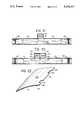
- FIG. 18is a cross-sectional view of the corner area of a bus or other mass transit vehicle, on which is mounted an advertising card carrier and an elongated illuminating source according to the present invention.
- FIG. 19shows an upwardly directed plan view of the arrangement of FIG. 18 viewed along line 119 thereof.
- FIG. 20is a diagrammatic cross-sectional view of the structure of FIGS. 18 and 19 viewed along line 20--20 thereof.
- FIG. 21is a similar diagrammatic longitudinal cross-sectional view of a modification of the arrangement of FIG. 20.
- FIG. 22shows a fragmentary prospective view of one form of the card carrying panel of FIGS. 18-21, accommodating ventilating openings.
- a sign 1is illuminated by evenly distributed colored light from a multi-colored illumination arrangement.
- This arrangementincludes a light source 4 with reflector, an inner tube 2, an outer tube 3, reflectors 6, 11, a diffusing medium 12, a high reflectance light-distribution film 13, and a motor assembly 7.
- the reflector 6is angled to reflect light emanating from the light source 4 into the inner tube 2.
- the reflector 6is preferably made of 3M SILVERLUX material or like reflecting material.
- the lightthen propagates inside the inner tube by reflecting off the high reflectance film or sheet 13, which is preferably 3M SCOTCHLAMP film or the like, whose properties are described below.
- Reflector 11is arranged at the end of the inner tube 2 furthest from the light source 4 so as to reflect propagated light back into the inner tube 2. Reflector 11 may be of the same material as reflector 6.
- the diffusing medium 12which may be a dull white (or other desired color) strip or coating to cause diffusion or scattering of the light impinging thereon, extends along the length of the inner tube 2 near the bottom, as seen in FIG. 3.
- the diffusing medium 12is substantially diametrically opposite a longitudinally extending light-transmissive portion 14 (which may be an opening, not shown) in the wall of the inner tube 2, which registers with a gap 14A in the film 13.
- the lightdiffuses or scatters, with some passing through the light-transmissive portion 14.
- the restis multiply reflected by film 13, ultimately striking diffusing medium 12 to pass through light-transmissive portion 14.
- the diffusing mediummay be laid or coated on the inner surface of the film 13. Alternately, the film 13 and tube 2 may have a longitudinal slot or recess into which the diffusing medium is placed.
- the high reflectance film 13is a thin, flexible, clear transparent material, such as acrylic or polycarbonate polymer, with a smooth surface on one side and prismatic grooves on the other side, which form on the surface of inner tube 2 tiny optical prisms that extend longitudinally along tube 2.
- FIG. 1schematically shows a light guide tube 35 and an external light source 33 with a reflector surrounding it.
- the light guide tube 35is formed of Scotchlamp material, having a transparent wall with a grooved outer surface forming prismatic elements, which are efficient total internal reflection surfaces and prevent light which is travelling down the guide tube from escaping through the film 13.
- Each prismatic elementhas two prism faces inclining outward towards each other and into contact with each other so as to have a V-like shape. These are more clearly shown in FIGS. 2 and 3.
- a light ray 31emitted from the external light source 33, strikes the interior of the transparent wall of guide tube 35, through which the light refracts in accordance with Snell's law to pass through the body of the transparent wall.
- the raystrikes one prism face at any angle less than the critical angle for total internal reflection, it reflects by total internal reflection and heads for the other prism face of the same prismatic element. If reflected by total internal reflection again, it returns to the interior of the tube for further propagation. A ray will be reflected if the angle it makes with the tube axis is less than about 27 degrees. The exact angular value is dependent upon the refractive index of the transparent material.
- the film 13is formed to reflect the light and to minimize absorption and transmission. Absorption per bounce
- the light rayUpon reaching the end of the tube 35 which is furthest from the light source 33, the light ray is reflected by a reflector 37 back into the guide tube 35.
- a white surface 15may be added between the inner tube 2 and the high reflectance film 13 as shown in FIG. 7.
- light which may be transmitted through the film 13, which would otherwise constitute a residual transmission loss,is diffused or reflected back into the inner tube from the white surface 15 and is thereby retained to enhance efficiency.
- the outer tube 3concentrically surrounds the inner tube 2.
- a motor assembly 7is used to rotatably position the outer tube 3 relative to the inner tube 2 in any conventional manner.
- the outer tube 3is formed of a number of longitudinal light-transmissive (transparent or translucent) colored filter sections (as seen in FIG. 6), any one section being positionable to be opposite the light-transmissive portion 14.
- the color filter segments of the outer tube 3may be in the form of either transparent color inserts suitably held to the outer tube, as by projecting lips, or transparent color silk-screened onto the segments of the tube 3.
- the outer tube 3is divided into color quadrants, each quadrant having a different color such as green G, red R, yellow Y, and blue or black B, each of which extends along substantially the full length of the outer tube 3. In this way the light then projects outwardly from the entire length of the sign 1 to effect illumination of the sign 1 with a single colored light.
- each color-transmitting sectionWhen used in a bus sign, for example, the colored light transmitted by the colored filter sections R, Y, G, B may not be highly visible in daylight, and such colored light-transmitting filter sections are usually poor light reflectors, leading to poor daylight visibility.
- Thismay be overcome by making each color-transmitting section partially efficiently light-transmissive and partially efficiently light-reflective.
- each section R, Y, G or Bmay be formed of alternate stripes 41 of color-filter material (shown stippled) and intervening stripes 43 of color-reflecting material.
- the color-filtering and color-reflecting materialsare preferably chosen to have closely similar color as perceived either in daylight or night-time.
- a controller or a computermay be used to control the positioning of the outer tube 3 so that a desired color segment R, Y, G, or B will be exposed, either to filter the light passing through the light-transmissive portion of the inner tube 2 or to be reflected by ambient light.
- the light source 4does not necessarily have to be arranged perpendicular to the axis of the inner tube 2. Any angular orientation can be used if accompanied by an appropriate position of the reflector 6 to reflect the light nearly axially into the inner tube 2. If the light source 4 and the inner tube 2 are substantially co-linearly arranged, no reflector 6 is needed.
- a reflectormay be used surrounding the light source or bulb, to focus the light rays to be substantially axial of or slightly converging along the tube, as indicated schematically in FIG. 6.
- a perpendicular orientation for the light source axisis preferred to obtain better accessibility to the light source bulb for replacement purposes, and to reduce the axial dimensions of the system. This is advantageous when the sign to be illuminated is on a bus, since there may be insufficient space available at the side of the sign for gaining access to the bulb and effecting removal and replacement when needed.
- FIG. 7shows a schematic sectional view of the inner tube alone, depicting the path of certain light rays.
- the only light emitted to the exterioris through the light-transmissive portion 14, derived from the diffusing medium 12.
- the film 13 on the inner surface of tube 2 between diffusing medium 12 and the light-transmissive portion 14serves primarily to distribute the light uniformly along the length of the tube 2, without directly passing through the light-transmissive portion 14. After multiple reflections, the light ultimately hits the diffusing medium 12.
- Those rays from diffusing medium 12 which do not exit from the light-transmissive portion 14are internally reflected and multiply, with little loss, to impinge again on diffusing medium 12. Thus, ultimately nearly all the light energy is emitted through the light-transmissive portion 14, with very little loss.
- FIG. 9shows a view similar to FIG. 7 for a second embodiment.
- an opaque tube 2Awhich may be an aluminum or plastic extrusion or pultrusion, is used in the same way as inner tube 2.
- the opaque inner tube 2Aalso has a portion lined with the high reflectance film 13 except for an unlined portion or gap in the form of a longitudinal slit in which is placed a lens 8 which longitudinally extends along a length of the tube 2A.
- the inner surface of the tube 2Ais made white or reflective so that light transmitting through the film diffuses or reflects back into the tube 2A and is thereby retained.
- the lens 8may be designed in known manner to provide a more uniform illumination from the bottom to the top of a sign 1 (see FIG. 6) and to adjust for the shorter path length for light rays impinging on the lower portion of the sign 1.
- the lens 8may be linear, prismatic, clear and illustratively is composed of polycarbonate material.
- a diffusing medium 5is also arranged diametrically opposite the lens 8 and, for improved uniformity of light distribution along the tube length, may be of a varying width.
- the diffusing medium 5widens as it extends longitudinally away from the light source 4 in the embodiment of FIG. 5.
- the diffusing mediummay have a width 5A of 0.43 inches nearest the light source, a width 5B of 0.58 inches about midway along the length of the inner tube 2, and a width 5C of 0.88 inches furthest from the light source 4 or nearest the end reflector 6.
- This varying widthmay be provided by bulging the diffusing material to provide a varying curved-surface width along the length of tube 2A.
- Thismay be provided, for example, by forming a uniform width groove or slot in the tube 2A, with edges to retain a strip of diffusing material of gradually varying width, providing gradually varying bulging of the strip along its length.
- This varying widthaids in providing uniformity of illumination along the length of the light tube 2 by compensating for a tendency for a greater amount of light to pass through the light-transmissive portion 14 nearer the source than at the remote end of tube 2A.
- the lens 8which is preferable of a unitary one-piece construction, may have two or more transverse sections 8A and 8B. Such sections are useful to project the diffused light rays on either side of the centerline 16 of FIG. 9 to effect more uniform illumination over a sign such as sign 1.
- Each lens section 8A, 8Bhas a sloping surface relative to the centerline 16 so as to refract the light which is emitted from the curved surface of the diffusing medium 5, to distribute the light more uniformly over sign 1.
- each lens sectionmay actually be a separate lens with its own refractive index different from that of the other.
- the light source 4is preferably an incandescent halogen lamp which has advantages over a fluorescent lamp.
- one 20 watt incandescent halogen lampcan replace two 20 watt fluorescent lamps while providing an improved lighting effect.
- Such halogen lampsprovide higher intensities, with a narrower beam, more uniform brightness (top to bottom of sign), easy relamping through the back, lower cost and fewer components (socket and lamp versus two lamps, two sockets, a ballast and wiring channel), and require less input power (e.g. 20 watts versus 43 watts).
- such lampsproduce ultra-violet light which can be made to interact with fluorescent material on the illuminated surface to give enhanced brightness or special effects.
- the showing of darkened letters at each end of the sign or of a halo of light along the bottom of the signis inhibited by the use of the present invention with halogen lamps.
- the electronic signemploys yellow dots or disks for the lettering, these dots or disks remain yellow in appearance in light from the halogen lamp rather than appearing yellow-green as would be common with light from fluorescent lamps.
- tube 2 or 2Amay be split longitudinally and at the diffusing medium 5, and thus formed in two nearly half-cylinder sections.
- the two halvesmay be joined, together with the lens 8 and diffusing medium 5, by an end ring or cylinder, which for example may carry a gear to be driven by the motor drive assembly.
- the illumination arrangement of the present inventionmay be used to provide forward-facing selectable-color light bars.
- Multiple multi-color illumination arrangements of the inventionmay also be arranged end to end, as seen in FIG. 10. That figure illustrates use of the present invention in a bus destination sign display, having a section 51 displaying a bus route number, a section 53 displaying a bus destination (e.g., "DOWNTOWN") and three sections 54, 55, 56, each of which is a structure as described above which displays an elongated bar of a selectable color R, Y, G, B.
- a bus destination sign displayhaving a section 51 displaying a bus route number, a section 53 displaying a bus destination (e.g., "DOWNTOWN") and three sections 54, 55, 56, each of which is a structure as described above which displays an elongated bar of a selectable color R, Y, G, B.
- 3-color codesup to 64 in number, may be displayed, which would be intelligible at a greater distance than letters or numbers may be legible.
- sections like 54, 55, 56may be used as desired, to afford a greater variety of codes.
- the inner tubescommunicate with each other at their adjacent ends, which are then left open, with a single light source at one end or a light source at each end.
- the motor drive assemblies for such arrangementsare then arranged to act on the respective outer tubes but not to interfere with light communication between the inner tubes.
- each segmentmay be an independent unit, with its own light source and motor drive.
- image enhancer plates 9are shown on either side of the gap 14A, inclining inward from a housing assembly 10 towards the outer tube 3. These plates 9 are light-reflective and increase the apparent size of a colored segment of the color tube 3. These image enhancer plates 9 ideally extend longitudinally along the entire length of the outer tube 3 and may further extend transversely at the ends of the outer tube so as to incline outward along the entire periphery of the outer tube's color segment which is exposed to light from the inner tube 2 or 2A.
- the image enhancer plates 9may incline outward from adjacent the periphery of the light-transmissive portion of the inner tube 2 or 2A. Such arrangements may also be used to enhance the light passing through the light-transmissible portion when no color-creating outer tube 3 is employed.
- the image enhancer plates 9help to uniformly distribute and enhance the illuminating effect of the light transmitting through the light-transmissible portion by reflecting light which would not have been directed at the object or sign to be illuminated and thus would have been lost.
- the enhancer platesthereby capture this otherwise lost light.
- FIGS. 14-15show an improved arrangement where color 15 change is not needed.
- the housing 61contains a stationary light guide arrangement 63 whose construction may be that of FIG. 7 or FIG. 9 without the outer tue or its drive.
- a light source assembly 65is located at each end, comprising a light bulb 67 and reflector 69 for directing light along light guide 63.
- the assembly 65is pivoted at 71 so that it may be extended beyond housing 61 through an opening 73, as seen in dashed line in FIG. 15, to permit easy replacement of bulb 67 when needed.
- Conventional latching means(not shown) usually retain each source 65 in operative position as shown in FIG. 14.
- Housing 61is open along one side 75.
- an extended generally uniform illuminationis provided, of any desired length, determined by the length of light guide arrangement 63.
- FIGS. 16 and 17show a modified arrangement of the arrangement of FIGS. 14 and 15.
- the housing 161is formed of a clear transparent plastic having a light-transmitting face 162 and a back portion 163 where the clear transparent plastic is covered by an opaque coating, such as of black lacquer 164a.
- Juxtaposed on the inner side of the clear housing face 162is a flat plate or sheet 164 formed on the same transreflective material as the light guide arrangement described above with respect to FIG. 3.
- a curved sheet 166of the same transreflective light guide material.
- Flat sheet 164 and curved sheet 166together formed cylindrical light guide arrangement as above, but of non-circular cross section.
- each light assembly 165is pivoted at 168 to the housing 163 so that, as shown in the left portion of FIG. 16, the light assembly 165 may be pivoted by 90° to make the light bulb 167 accessible for replacement purposes.
- the light assembly 165is formed of a support 170 carrying a curved reflector 172 which may be of parabolic shape.
- a lamp socket(indicated generally at 174) into which a light bulb 167 may be plugged.
- the light bulb socket 174has contacts (not shown) which engage the terminals of the light bulb 166 and are connected to terminals 165 for electrical connection to a suitable source of electrical power.
- the light bulb 167extends generally axially of the housing 163 with its reflector 172 behind it, when the assembly is in the operative position shown at the right side of FIG. 16.
- the light bulb 167therefore projects its light along the interior of the housing longitudinally of the cylindrical light guide formed by 164,166.
- the properties of the light guideare as described above, so that light rays impinging at a shallow angle on the interior of the light guide are reflected inwardly. Those rays that travel the length of the housing 163 will then be reflected by the reflector 172 at the opposite end. Accordingly, the light rays travel back and forth within the light guide. Certain of the rays impinging on the sheets 164, 166 may be refracted by the material of the light guide and exit from the light guide. To preserve efficiency, the interior 178 of the housing 163 which surrounds the curved light guide sheet 166 is coated or painted white, so that any light which may exit from the light guide is in turn reflected or diffracted back into the light guide. Alternatively, the transparent housing may be coated white on its exterior, beneath any black or opaque outer coating.
- a central portion of the curved light guide sheet 166may (but need not) have a diffusing strip 176 extending along its length diametrically opposite from the clear face 162 of the housing 161.
- the flat sheet 164preferably has a length greater than that of the curved sheet 166 so that the curved light guide sheet 166 covers only the central part of the length of the housing 161.
- the curved sheet 166backs up only a portion of the flat sheet 164, leaving end portions 162A of the flat sheet 162 unbacked by the curved sheet 166, but backed by the white surface 178 of the interior of the housing 161.
- the white sections 178 at each end of the housingserve as diffusing and reflecting areas from which light rays are directed nearly perpendicularly or at other angles to sheet 164. These light rays may pass through sheet 164 and provide illumination.
- the flat or front face 162 of the housingmay extend to a region 181 at the top edge of the housing 163 at an angle to the front face. Therefore, particularly in the regions to which the curved light guide sheet 166 does not extend, light rays may exit directly through the clear area 181 of the housing 161 for further regulation of the distribution of the light emitted from this arrangement.
- the housing 161may have a flattened corner shown at 177, which forms a surface for mounting the housing under a shelf or light shield.
- the clear region 181thus illuminate generally forwardly while the front face 162 would illuminate generally at a downward angle, and provides a diffused light source essentially without glare. This is particularly useful for illuminating instrument panels of an aircraft, beneath a glare shield under which the arrangement may be mounted.
- sheet 164 and areas 178may be suitably colored if desired.
- a stationary single-color outer tubemay be used in place of the rotatable outer tube, or the outer tube may be dispensed with entirely.
- the diffusing strip 12may be appropriately colored, when desired to provide a non-white illumination, such as for photographic dark rooms or night illumination of instrument panels.
- an extended-length source of infra-red or ultra-violet lightmay be provided by the present arrangement by placing an appropriate infra-red or ultra-violet filter between light source 4 or 65 and the light guide, or otherwise inputting only infra-red or ultra-violet light to the light guide.
- FIGS. 18-22show applications of the invention to use in a bus or other mass transit vehicle for both general illumination and for illuminating advertising cards.
- FIG. 18shows a cross-section of the corner area of a bus having an inner skin or lining 101 (which may be made of plastic, e.g. by pultrusion, or of sheet metal) curving from the ceiling 101a to the side wall 101b of a bus.
- FIG. 19shows a small scale, partially broken away, upwardly looking plan view of the devices of FIG. 18, viewed in direction A of FIG. 18, to show a series of several light fixtures along the length of the passenger compartment.
- Extending along the length of the passenger compartment of the busis a series of lighting fixtures 102, each having a panel 103 for supporting an advertising card 105 between a lower groove formed on the panel 103 by a lip 107 and an upper groove formed by a similar lip 109.
- the panelis shown as connected to the side wall 101b of the bus by a suitable flange or bracket arrangement 111 at its lower edge.
- the card carrying panel 103is illustratively supported from a light tube 113 similar to that of FIG. 7 or 9.
- the light tube 113is illustratively shown as formed as an extrusion (for example from aluminum or plastic resin) or a pultrusion of fiberglass).
- first bracket 115 and a second bracket 117Formed as part of the light tube 113 is a first bracket 115 and a second bracket 117, extending along tube 113. Each bracket is secured by suitable means (illustrated as screws 119) from the ceiling 101a of the vehicle. Bracket 115 may be omitted, relying upon bracket 143 and bracket 117 to support the light tube 113.
- Light tube 113preferably has a varying width diffusion member 125 corresponding to element 5 of FIG. 9, opposite a longitudinally extending opening 127.
- the light tubeis formed with a pair of grooves 131, 133 within which is retained a light transmissive strip 137 which may be of clear plastic, or translucent plastic serving as a light diffuser or, formed as a fresnel-type lens for distributing the light emitted from the light tube over both the reading area of the bus, between the arrows RR and also on the advertising card 105.
- the light tube member 113is also formed with a groove 138 which engages a small flange 139 at the upper edge of the card carrier panel 103. This flange is also shown more clearly in FIG. 22 and is described more in detail below.
- the light tube 113also provides an arrangement for helping support a hand rail 141 by means of a bracket 143 having a rail supporting section 145.
- the bracket 143has a groove 147 at one edge engaging an extension 149 formed on the tube 113.
- Tube 113contains two strips of trans-reflective material 114 except the opening 127 and at the position of the diffusing element 12, to form the interior light-reflecting arrangement described above.
- brackets 143are spaced along the length of the vehicle passenger compartment by appropriate distances, as may be desired for proper structural strength. Any other desired means for supporting the hand rail may be used.
- the light tube holder 113is formed in
- FIG. 21illustrates how light may be supplied to each light tube section, in a manner similar to FIG. 4 or 6.
- a light housing 157At one end of a light tube 113 is a light housing 157.
- a lamp 153 in light housing 157is supported in a socket arrangement 151 and projects light to a 45-degree prism or mirror 155, which changes the direction of light from the lamp 153 to be substantially axial along the light tube 113.
- Lamp 153may be a high-intensity halogen lamp (e.g., 20 to 40 watts) with a reflector associated with it.
- a mirror 157may be placed at the far end of the light tube 113 from the light source 153.
- a second and similar light housingmay be placed at the far end of the tube 113.
- two light sources 153 and 153' in respective housings 157 and 157'are placed at the same location.
- the light tubesare, for example, six feet in length, the light sources would be placed approximately every twelve feet, at locations convenient for maintenance purposes.
- the web of bracket 117 in conjunction with the ceiling lining 101 and the card carrier panel 103define a duct which may be used for the distribution of fresh or heated or cooled conditioned air, as desired.
- openings 161are provided in the card carrier panel 103 as shown more clearly in FIG. 22. These openings are distributed in accordance with the requirements for ventilation and passenger comfort in the passenger compartment of the vehicle.
- a curved panel 162may extend from the light tube 113 in an arc across the center of the ceiling of the vehicle, to a similar light tube 113 (of mirror image confirmation in relation to that shown in FIG. 18).
- the space between the panel 161 and the ceiling lining 101amay be filled with insulating material or used for accommodating wires for the vehicle electrical system, including the lighting fixtures described below.
- tube 113 and panel 103have been described illustratively as made from separate extrusions or pultrusions, a single composite extrusion or pultrusion having the desired profile may be used where expedient.
- each section of light tube 113may be provided with a light source as shown, at either or both ends.
- the form of light source shown in FIG. 16may be used in place of those in FIGS. 18-22, with each light source suitably mounted as shown in FIG. 16, for ready lamp replacement when needed.
Landscapes
- Physics & Mathematics (AREA)
- Engineering & Computer Science (AREA)
- General Physics & Mathematics (AREA)
- Mechanical Engineering (AREA)
- Optics & Photonics (AREA)
- General Engineering & Computer Science (AREA)
- Spectroscopy & Molecular Physics (AREA)
- Theoretical Computer Science (AREA)
- Illuminated Signs And Luminous Advertising (AREA)
Abstract
Description
Claims (26)
Priority Applications (1)
| Application Number | Priority Date | Filing Date | Title |
|---|---|---|---|
| US07/697,306US5219217A (en) | 1988-10-07 | 1991-05-08 | Illuminating system |
Applications Claiming Priority (3)
| Application Number | Priority Date | Filing Date | Title |
|---|---|---|---|
| US07/255,062US4996632A (en) | 1988-10-07 | 1988-10-07 | Multi-color illuminating system |
| US07/395,889US5016143A (en) | 1988-10-07 | 1989-08-18 | Illuminating system |
| US07/697,306US5219217A (en) | 1988-10-07 | 1991-05-08 | Illuminating system |
Related Parent Applications (1)
| Application Number | Title | Priority Date | Filing Date |
|---|---|---|---|
| US07/395,889Continuation-In-PartUS5016143A (en) | 1988-10-07 | 1989-08-18 | Illuminating system |
Publications (1)
| Publication Number | Publication Date |
|---|---|
| US5219217Atrue US5219217A (en) | 1993-06-15 |
Family
ID=27400825
Family Applications (1)
| Application Number | Title | Priority Date | Filing Date |
|---|---|---|---|
| US07/697,306Expired - Fee RelatedUS5219217A (en) | 1988-10-07 | 1991-05-08 | Illuminating system |
Country Status (1)
| Country | Link |
|---|---|
| US (1) | US5219217A (en) |
Cited By (34)
| Publication number | Priority date | Publication date | Assignee | Title |
|---|---|---|---|---|
| US5481637A (en)* | 1994-11-02 | 1996-01-02 | The University Of British Columbia | Hollow light guide for diffuse light |
| WO1997036199A1 (en)* | 1996-03-22 | 1997-10-02 | The University Of British Columbia | Light guide employing multilayer optical film |
| US5761060A (en)* | 1996-06-25 | 1998-06-02 | University Of Utah | System and method for evaluating sign legibility |
| EP0795468A3 (en)* | 1996-03-15 | 1999-05-19 | DaimlerChrysler Aerospace Airbus Gesellschaft mit beschränkter Haftung | Lightning system for passenger compartiment, specially for an aircraft |
| US6014489A (en)* | 1997-06-13 | 2000-01-11 | Johanson; Walter A. | Light distributing tubes and methods of forming same |
| US6215409B1 (en)* | 1996-05-17 | 2001-04-10 | Solaglo Pty Ltd. | Display apparatus |
| US6267492B1 (en)* | 1999-04-15 | 2001-07-31 | 3M Innovative Properties Company | Illumination device with side emitting light guide |
| US6449890B1 (en)* | 1999-07-21 | 2002-09-17 | Nec Infrontia Corporation | Display element lighting method and display device |
| US6510633B1 (en) | 2000-06-23 | 2003-01-28 | William C. Bledsoe | Panel illustration apparatus |
| US6592238B2 (en) | 2001-01-31 | 2003-07-15 | Light Technologies, Inc. | Illumination device for simulation of neon lighting |
| US20030174516A1 (en)* | 2002-03-12 | 2003-09-18 | Tyco Electronics Canada | Apparatus, methods and articles of manufacture for a co-extruded light pipe |
| US20040066654A1 (en)* | 2002-10-04 | 2004-04-08 | Tir Systems Ltd. | Color-corrected hollow prismatic light guide luminaire |
| US20040093779A1 (en)* | 2001-03-27 | 2004-05-20 | Tomasz Blach | Illuminated background display apparatus |
| US20040124757A1 (en)* | 2002-12-27 | 2004-07-01 | Chow Shing Cheung | Fluorescent lamp |
| US20040168359A1 (en)* | 2003-02-04 | 2004-09-02 | Cleaver Mark J. | Flexible illumination device for simulating neon lighting |
| US6874924B1 (en) | 2002-03-14 | 2005-04-05 | Ilight Technologies, Inc. | Illumination device for simulation of neon lighting |
| US7008097B1 (en) | 2003-02-25 | 2006-03-07 | Ilight Technologies, Inc. | Illumination device for simulating neon or fluorescent lighting including a waveguide and a scattering cap |
| US20060164607A1 (en)* | 2005-01-25 | 2006-07-27 | Morejon Israel J | Light-emitting diode (LED) illumination system for a digital micro-mirror device (DMD) and method of providing same |
| US7118251B1 (en) | 2003-05-23 | 2006-10-10 | Ilight Technologies, Inc. | Illumination device for simulating channel letters |
| US20080037943A1 (en)* | 2006-08-11 | 2008-02-14 | Lg Electronics Inc. | Light pipe having a structure of enhancing an emission of a light |
| US20080089654A1 (en)* | 2006-10-13 | 2008-04-17 | Sang Hoon Lee | Light pipe having an improved structure of prisms |
| US20090021955A1 (en)* | 2007-07-17 | 2009-01-22 | I/O Controls Corporation | Control network for led-based lighting system in a transit vehicle |
| US20090161364A1 (en)* | 2007-12-20 | 2009-06-25 | Erco Leuchten Gmbh | Prism lens and light fixture |
| US20090237950A1 (en)* | 2008-03-24 | 2009-09-24 | I/O Controls Corporation | Low glare lighting for a transit vehicle |
| US20100110282A1 (en)* | 2008-10-30 | 2010-05-06 | Silitek Electronic (Guangzhou) Co., Ltd. | Camera lens module and manufacturing method thereof |
| US20100195346A1 (en)* | 2009-02-05 | 2010-08-05 | Valeo Vision | Optical device, in particular for an automotive vehicle, such as a lighting or signaling device |
| US8029175B2 (en)* | 2008-05-22 | 2011-10-04 | Koito Manufacturing Co., Ltd. | Vehicle lighting apparatus |
| CN102338325A (en)* | 2010-07-23 | 2012-02-01 | 陈晓锋 | a decorative lighting |
| US20140346370A1 (en)* | 2013-05-23 | 2014-11-27 | Sensor Electronic Technology, Inc. | Reflective Transparent Optical Chamber |
| US20150234118A1 (en)* | 2012-09-20 | 2015-08-20 | Thomson Licensing | Panel illumination system |
| US9815501B2 (en) | 2014-10-21 | 2017-11-14 | Great Dane Llc | Cargo vehicle and molding assembly for a cargo vehicle |
| CN110778946A (en)* | 2019-11-18 | 2020-02-11 | 隋功然 | LED projection lamp device |
| US12145502B2 (en)* | 2022-09-30 | 2024-11-19 | Toyoda Gosei Co., Ltd. | Lighting device |
| EP4592995A1 (en)* | 2024-01-23 | 2025-07-30 | Qbuzz B.V. | Destination sign system for a public transport vehicle |
Citations (32)
| Publication number | Priority date | Publication date | Assignee | Title |
|---|---|---|---|---|
| US569764A (en)* | 1896-10-20 | Charles l | ||
| US1615449A (en)* | 1925-03-27 | 1927-01-25 | Clarence A Fullerton | Display sign |
| US1741748A (en)* | 1927-04-12 | 1929-12-31 | Harry F White | Illuminated sign |
| FR688289A (en)* | 1929-01-15 | 1930-08-21 | Chauffage & Eclairage Modernes | Improvements to daytime and illuminated sign devices |
| US1837091A (en)* | 1930-04-26 | 1931-12-15 | Wayne W Adams | Lighting system |
| US2018732A (en)* | 1933-05-22 | 1935-10-29 | Bruce B Krost | Merchandising display lighting fixture |
| US2041909A (en)* | 1934-04-13 | 1936-05-26 | Emil J Paidar Company | Means for barber pole illumination |
| US2374640A (en)* | 1943-09-16 | 1945-04-24 | Leslie R Paul | Color control |
| US2493829A (en)* | 1946-02-12 | 1950-01-10 | Leslie R Paul | Illuminating device |
| US2520028A (en)* | 1947-01-08 | 1950-08-22 | Morton S Biskind | Maximum indicating instrument |
| US2567403A (en)* | 1947-02-20 | 1951-09-11 | Rock Ola Mfg Corp | Illuminative device for projecting continuously changing color designs |
| US2587807A (en)* | 1947-07-25 | 1952-03-04 | Patent License Corp | Car lighting structure |
| US2795069A (en)* | 1956-02-07 | 1957-06-11 | George K C Hardesty | Laminated metal-plastic illuminable panel |
| US2831283A (en)* | 1953-10-16 | 1958-04-22 | Westinghouse Air Brake Co | Three-position illuminated indicators |
| US3035161A (en)* | 1960-06-06 | 1962-05-15 | Budd Co | Vehicle ceiling with lighting fixture |
| US3302012A (en)* | 1963-06-29 | 1967-01-31 | Dornier Werke Gmbh | Lighting system utilizing the floodlight principle |
| US3399476A (en)* | 1965-02-01 | 1968-09-03 | James F. Davis | Animated sign |
| US3486261A (en)* | 1965-10-22 | 1969-12-30 | George K C Hardesty | Illuminating apparatus |
| DE2645311A1 (en)* | 1976-10-07 | 1978-04-13 | Julian Borisovitsch Aisenberg | Covered construction sites lighting installation - uses hollow slot light conductor with at least one optical inlet and light source attached to light conductor |
| US4260220A (en)* | 1979-06-15 | 1981-04-07 | Canadian Patents And Development Limited | Prism light guide having surfaces which are in octature |
| US4387415A (en)* | 1979-04-30 | 1983-06-07 | Transmatic, Inc. | Cornice lighting fixture |
| US4525772A (en)* | 1983-06-07 | 1985-06-25 | Britax Vega Limited | Vehicle lamp assembly |
| US4558401A (en)* | 1981-08-29 | 1985-12-10 | Britax Vega Limited | Vehicle lamp assembly |
| US4561043A (en)* | 1984-09-27 | 1985-12-24 | Thompson Gary J | Decorative light display |
| DE8606421U1 (en)* | 1986-03-08 | 1986-05-22 | Koch, Bodo, 5000 Koeln | Light display |
| FR2591717A1 (en)* | 1985-12-17 | 1987-06-19 | Agency Ind Science Techn | LIGHT SOURCE DEVICE, IN PARTICULAR FOR MANAGEMENT OR OFFICE MACHINE |
| US4750798A (en)* | 1983-08-29 | 1988-06-14 | Canadian Patents And Developement Limited | Prism light guide luminaire |
| US4805984A (en)* | 1985-11-21 | 1989-02-21 | Minnesota Mining And Manufacturing Company | Totally internally reflecting light conduit |
| US4947293A (en)* | 1989-03-03 | 1990-08-07 | Johnson Glenn M | Cargo vehicle perimeter clearance lighting system |
| US4996632A (en)* | 1988-10-07 | 1991-02-26 | Gulton Industries, Inc. | Multi-color illuminating system |
| US5006966A (en)* | 1989-08-30 | 1991-04-09 | Transmatic, Inc. | Transit vehicle lighting fixture |
| US5113322A (en)* | 1989-08-30 | 1992-05-12 | Transmatic, Inc. | Transit vehicle lighting fixture |
- 1991
- 1991-05-08USUS07/697,306patent/US5219217A/ennot_activeExpired - Fee Related
Patent Citations (34)
| Publication number | Priority date | Publication date | Assignee | Title |
|---|---|---|---|---|
| US569764A (en)* | 1896-10-20 | Charles l | ||
| US1615449A (en)* | 1925-03-27 | 1927-01-25 | Clarence A Fullerton | Display sign |
| US1741748A (en)* | 1927-04-12 | 1929-12-31 | Harry F White | Illuminated sign |
| FR688289A (en)* | 1929-01-15 | 1930-08-21 | Chauffage & Eclairage Modernes | Improvements to daytime and illuminated sign devices |
| US1837091A (en)* | 1930-04-26 | 1931-12-15 | Wayne W Adams | Lighting system |
| US2018732A (en)* | 1933-05-22 | 1935-10-29 | Bruce B Krost | Merchandising display lighting fixture |
| US2041909A (en)* | 1934-04-13 | 1936-05-26 | Emil J Paidar Company | Means for barber pole illumination |
| US2374640A (en)* | 1943-09-16 | 1945-04-24 | Leslie R Paul | Color control |
| US2493829A (en)* | 1946-02-12 | 1950-01-10 | Leslie R Paul | Illuminating device |
| US2520028A (en)* | 1947-01-08 | 1950-08-22 | Morton S Biskind | Maximum indicating instrument |
| US2567403A (en)* | 1947-02-20 | 1951-09-11 | Rock Ola Mfg Corp | Illuminative device for projecting continuously changing color designs |
| US2587807A (en)* | 1947-07-25 | 1952-03-04 | Patent License Corp | Car lighting structure |
| US2831283A (en)* | 1953-10-16 | 1958-04-22 | Westinghouse Air Brake Co | Three-position illuminated indicators |
| US2795069A (en)* | 1956-02-07 | 1957-06-11 | George K C Hardesty | Laminated metal-plastic illuminable panel |
| US3035161A (en)* | 1960-06-06 | 1962-05-15 | Budd Co | Vehicle ceiling with lighting fixture |
| US3302012A (en)* | 1963-06-29 | 1967-01-31 | Dornier Werke Gmbh | Lighting system utilizing the floodlight principle |
| US3399476A (en)* | 1965-02-01 | 1968-09-03 | James F. Davis | Animated sign |
| US3486261A (en)* | 1965-10-22 | 1969-12-30 | George K C Hardesty | Illuminating apparatus |
| DE2645311A1 (en)* | 1976-10-07 | 1978-04-13 | Julian Borisovitsch Aisenberg | Covered construction sites lighting installation - uses hollow slot light conductor with at least one optical inlet and light source attached to light conductor |
| US4387415A (en)* | 1979-04-30 | 1983-06-07 | Transmatic, Inc. | Cornice lighting fixture |
| US4387415B1 (en)* | 1979-04-30 | 1992-12-01 | Transmatic Inc | |
| US4260220A (en)* | 1979-06-15 | 1981-04-07 | Canadian Patents And Development Limited | Prism light guide having surfaces which are in octature |
| US4558401A (en)* | 1981-08-29 | 1985-12-10 | Britax Vega Limited | Vehicle lamp assembly |
| US4525772A (en)* | 1983-06-07 | 1985-06-25 | Britax Vega Limited | Vehicle lamp assembly |
| US4750798A (en)* | 1983-08-29 | 1988-06-14 | Canadian Patents And Developement Limited | Prism light guide luminaire |
| US4561043A (en)* | 1984-09-27 | 1985-12-24 | Thompson Gary J | Decorative light display |
| US4805984A (en)* | 1985-11-21 | 1989-02-21 | Minnesota Mining And Manufacturing Company | Totally internally reflecting light conduit |
| FR2591717A1 (en)* | 1985-12-17 | 1987-06-19 | Agency Ind Science Techn | LIGHT SOURCE DEVICE, IN PARTICULAR FOR MANAGEMENT OR OFFICE MACHINE |
| DE8606421U1 (en)* | 1986-03-08 | 1986-05-22 | Koch, Bodo, 5000 Koeln | Light display |
| US4996632A (en)* | 1988-10-07 | 1991-02-26 | Gulton Industries, Inc. | Multi-color illuminating system |
| US5016143A (en)* | 1988-10-07 | 1991-05-14 | Gulton Industries, Inc. | Illuminating system |
| US4947293A (en)* | 1989-03-03 | 1990-08-07 | Johnson Glenn M | Cargo vehicle perimeter clearance lighting system |
| US5006966A (en)* | 1989-08-30 | 1991-04-09 | Transmatic, Inc. | Transit vehicle lighting fixture |
| US5113322A (en)* | 1989-08-30 | 1992-05-12 | Transmatic, Inc. | Transit vehicle lighting fixture |
Cited By (52)
| Publication number | Priority date | Publication date | Assignee | Title |
|---|---|---|---|---|
| US5481637A (en)* | 1994-11-02 | 1996-01-02 | The University Of British Columbia | Hollow light guide for diffuse light |
| EP0795468A3 (en)* | 1996-03-15 | 1999-05-19 | DaimlerChrysler Aerospace Airbus Gesellschaft mit beschränkter Haftung | Lightning system for passenger compartiment, specially for an aircraft |
| USRE37594E1 (en) | 1996-03-22 | 2002-03-19 | The University Of British Columbia | Light guide employing multilayer optical film |
| WO1997036199A1 (en)* | 1996-03-22 | 1997-10-02 | The University Of British Columbia | Light guide employing multilayer optical film |
| US6215409B1 (en)* | 1996-05-17 | 2001-04-10 | Solaglo Pty Ltd. | Display apparatus |
| US5761060A (en)* | 1996-06-25 | 1998-06-02 | University Of Utah | System and method for evaluating sign legibility |
| US6014489A (en)* | 1997-06-13 | 2000-01-11 | Johanson; Walter A. | Light distributing tubes and methods of forming same |
| US6267492B1 (en)* | 1999-04-15 | 2001-07-31 | 3M Innovative Properties Company | Illumination device with side emitting light guide |
| US6449890B1 (en)* | 1999-07-21 | 2002-09-17 | Nec Infrontia Corporation | Display element lighting method and display device |
| US6510633B1 (en) | 2000-06-23 | 2003-01-28 | William C. Bledsoe | Panel illustration apparatus |
| US6592238B2 (en) | 2001-01-31 | 2003-07-15 | Light Technologies, Inc. | Illumination device for simulation of neon lighting |
| US20040093779A1 (en)* | 2001-03-27 | 2004-05-20 | Tomasz Blach | Illuminated background display apparatus |
| US20030174516A1 (en)* | 2002-03-12 | 2003-09-18 | Tyco Electronics Canada | Apparatus, methods and articles of manufacture for a co-extruded light pipe |
| US6769799B2 (en)* | 2002-03-12 | 2004-08-03 | Tyco Electronics Canada | Apparatus, methods and articles of manufacture for a co-extruded light pipe |
| US6874924B1 (en) | 2002-03-14 | 2005-04-05 | Ilight Technologies, Inc. | Illumination device for simulation of neon lighting |
| US20040066654A1 (en)* | 2002-10-04 | 2004-04-08 | Tir Systems Ltd. | Color-corrected hollow prismatic light guide luminaire |
| US6796686B2 (en)* | 2002-10-04 | 2004-09-28 | Tir Systems Ltd. | Color-corrected hollow prismatic light guide luminaire |
| US6836065B2 (en)* | 2002-12-27 | 2004-12-28 | Lap Lee Chow | Fluorescent lamp with uncoated region of fluorescent materil |
| US20040124757A1 (en)* | 2002-12-27 | 2004-07-01 | Chow Shing Cheung | Fluorescent lamp |
| US20050099109A1 (en)* | 2002-12-27 | 2005-05-12 | Lap Lee Chow | Fluorescent lamp |
| US20040168359A1 (en)* | 2003-02-04 | 2004-09-02 | Cleaver Mark J. | Flexible illumination device for simulating neon lighting |
| US8322883B2 (en) | 2003-02-04 | 2012-12-04 | Ilight Technologies, Inc. | Flexible illumination device for simulating neon lighting |
| US7008097B1 (en) | 2003-02-25 | 2006-03-07 | Ilight Technologies, Inc. | Illumination device for simulating neon or fluorescent lighting including a waveguide and a scattering cap |
| US7118251B1 (en) | 2003-05-23 | 2006-10-10 | Ilight Technologies, Inc. | Illumination device for simulating channel letters |
| US20060164607A1 (en)* | 2005-01-25 | 2006-07-27 | Morejon Israel J | Light-emitting diode (LED) illumination system for a digital micro-mirror device (DMD) and method of providing same |
| US7325956B2 (en)* | 2005-01-25 | 2008-02-05 | Jabil Circuit, Inc. | Light-emitting diode (LED) illumination system for a digital micro-mirror device (DMD) and method of providing same |
| EP1887389A3 (en)* | 2006-08-11 | 2008-03-05 | LG Electronics Inc. | Light pipe having a structure of enhancing an emission of a light |
| US20080037943A1 (en)* | 2006-08-11 | 2008-02-14 | Lg Electronics Inc. | Light pipe having a structure of enhancing an emission of a light |
| US20080089654A1 (en)* | 2006-10-13 | 2008-04-17 | Sang Hoon Lee | Light pipe having an improved structure of prisms |
| US7565050B2 (en) | 2006-10-13 | 2009-07-21 | Lg Electronics, Inc. | Light pipe having an improved structure of prisms |
| US20090021955A1 (en)* | 2007-07-17 | 2009-01-22 | I/O Controls Corporation | Control network for led-based lighting system in a transit vehicle |
| US9096168B2 (en) | 2007-07-17 | 2015-08-04 | I/O Controls Corporation | Control network for LED-based lighting system in a transit vehicle |
| US8786191B2 (en) | 2007-07-17 | 2014-07-22 | I/O Controls Corporation | Control network for LED-based lighting system in a transit vehicle |
| US8400061B2 (en) | 2007-07-17 | 2013-03-19 | I/O Controls Corporation | Control network for LED-based lighting system in a transit vehicle |
| US20090161364A1 (en)* | 2007-12-20 | 2009-06-25 | Erco Leuchten Gmbh | Prism lens and light fixture |
| US20090237950A1 (en)* | 2008-03-24 | 2009-09-24 | I/O Controls Corporation | Low glare lighting for a transit vehicle |
| US8740425B2 (en) | 2008-03-24 | 2014-06-03 | I/O Controls Corporation | Low glare lighting for a transit vehicle |
| US8210724B2 (en) | 2008-03-24 | 2012-07-03 | I/O Controls Corporation | Low glare lighting for a transit vehicle |
| US8029175B2 (en)* | 2008-05-22 | 2011-10-04 | Koito Manufacturing Co., Ltd. | Vehicle lighting apparatus |
| US8553142B2 (en)* | 2008-10-30 | 2013-10-08 | Lite-On Electronics (Guangzhou) Limited | Camera lens module and manufacturing method thereof |
| US20100110282A1 (en)* | 2008-10-30 | 2010-05-06 | Silitek Electronic (Guangzhou) Co., Ltd. | Camera lens module and manufacturing method thereof |
| US8579483B2 (en)* | 2009-02-05 | 2013-11-12 | Valeo Vision | Optical device, in particular for an automotive vehicle, such as a lighting or signaling device |
| US20100195346A1 (en)* | 2009-02-05 | 2010-08-05 | Valeo Vision | Optical device, in particular for an automotive vehicle, such as a lighting or signaling device |
| US8939625B2 (en) | 2009-02-05 | 2015-01-27 | Valeo Vision | Optical device, in particular for an automotive vehicle, such as a lighting or signalling device |
| CN102338325A (en)* | 2010-07-23 | 2012-02-01 | 陈晓锋 | a decorative lighting |
| US20150234118A1 (en)* | 2012-09-20 | 2015-08-20 | Thomson Licensing | Panel illumination system |
| US20140346370A1 (en)* | 2013-05-23 | 2014-11-27 | Sensor Electronic Technology, Inc. | Reflective Transparent Optical Chamber |
| US9415126B2 (en)* | 2013-05-23 | 2016-08-16 | Sensor Electronic Technology, Inc. | Reflective transparent optical chamber |
| US9815501B2 (en) | 2014-10-21 | 2017-11-14 | Great Dane Llc | Cargo vehicle and molding assembly for a cargo vehicle |
| CN110778946A (en)* | 2019-11-18 | 2020-02-11 | 隋功然 | LED projection lamp device |
| US12145502B2 (en)* | 2022-09-30 | 2024-11-19 | Toyoda Gosei Co., Ltd. | Lighting device |
| EP4592995A1 (en)* | 2024-01-23 | 2025-07-30 | Qbuzz B.V. | Destination sign system for a public transport vehicle |
Similar Documents
| Publication | Publication Date | Title |
|---|---|---|
| US5219217A (en) | Illuminating system | |
| US5016143A (en) | Illuminating system | |
| CA1331980C (en) | Illuminating system | |
| US7748148B2 (en) | Display sign adapted to be backlit by widely spaced light emitting diodes | |
| US5542201A (en) | Indirectly illuminated sign | |
| US5276591A (en) | Sign with indirect illumination from light emitting diodes | |
| EP1200772B1 (en) | Illumination apparatus | |
| US4561203A (en) | Opaque sign plaque with dual reflector illumination | |
| US6582103B1 (en) | Lighting apparatus | |
| JP2003519810A (en) | Lighting device and light emitting panel | |
| EP1173707B1 (en) | Shallow depth back lit illuminated signage | |
| JPH02234305A (en) | Illuminator to illuminate advertisment board,etc. | |
| US5966856A (en) | Illuminated sign light box | |
| US7077536B2 (en) | Double-sided edge lighting-type display light box | |
| US20060080874A1 (en) | Dynamic message sign | |
| EP1496489B1 (en) | Dynamic message sign | |
| GB2358513A (en) | Lighting apparatus and illuminated signs | |
| WO2006043943A1 (en) | Dynamic message sign | |
| JPH0841832A (en) | Internally illuminated road marking board | |
| EP0894318A1 (en) | Display signs | |
| JP2000148051A (en) | Illumination type signboard, and light emitting tube with light reflecting material | |
| JP3020353U (en) | Sign light emitting device | |
| RU2249255C2 (en) | Contour illumination light-dynamic electro-optical device | |
| KR870002552Y1 (en) | A advertising system | |
| KR100354242B1 (en) | License plate |
Legal Events
| Date | Code | Title | Description |
|---|---|---|---|
| AS | Assignment | Owner name:GULTON INDUSTRIES, INC., A CORP. OF DE Free format text:ASSIGNMENT OF ASSIGNORS INTEREST.;ASSIGNOR:AIKENS, WALLACE R.;REEL/FRAME:005787/0894 Effective date:19910611 | |
| FPAY | Fee payment | Year of fee payment:4 | |
| AS | Assignment | Owner name:LUMINATOR HOLDING, LLC, A NEW YORK LIMITED LIABILI Free format text:ASSIGNMENT OF ASSIGNORS INTEREST;ASSIGNOR:GULTON INDUSTRIES, INC., A DELAWARE CORPORATION;REEL/FRAME:008342/0060 Effective date:19970127 | |
| FPAY | Fee payment | Year of fee payment:8 | |
| AS | Assignment | Owner name:JPMORGAN CHASE BANK, AS ADMINISTRATIVE AGENT, TEXA Free format text:SECURITY AGREEMENT;ASSIGNOR:LUMINATOR HOLDING L.P., AS SUCCESSOR-IN-INTEREST TO LUMINATOR HOLDING LLC;REEL/FRAME:012983/0519 Effective date:20020531 | |
| REMI | Maintenance fee reminder mailed | ||
| LAPS | Lapse for failure to pay maintenance fees | ||
| STCH | Information on status: patent discontinuation | Free format text:PATENT EXPIRED DUE TO NONPAYMENT OF MAINTENANCE FEES UNDER 37 CFR 1.362 | |
| FP | Lapsed due to failure to pay maintenance fee | Effective date:20050615 |