US5219178A - Air bag inflation gas generator - Google Patents
Air bag inflation gas generatorDownload PDFInfo
- Publication number
- US5219178A US5219178AUS07/751,713US75171391AUS5219178AUS 5219178 AUS5219178 AUS 5219178AUS 75171391 AUS75171391 AUS 75171391AUS 5219178 AUS5219178 AUS 5219178A
- Authority
- US
- United States
- Prior art keywords
- combustion chamber
- gas
- generating agents
- air bag
- gas generating
- Prior art date
- Legal status (The legal status is an assumption and is not a legal conclusion. Google has not performed a legal analysis and makes no representation as to the accuracy of the status listed.)
- Expired - Fee Related
Links
Images


Classifications
- B—PERFORMING OPERATIONS; TRANSPORTING
- B60—VEHICLES IN GENERAL
- B60R—VEHICLES, VEHICLE FITTINGS, OR VEHICLE PARTS, NOT OTHERWISE PROVIDED FOR
- B60R21/00—Arrangements or fittings on vehicles for protecting or preventing injuries to occupants or pedestrians in case of accidents or other traffic risks
- B60R21/02—Occupant safety arrangements or fittings, e.g. crash pads
- B60R21/16—Inflatable occupant restraints or confinements designed to inflate upon impact or impending impact, e.g. air bags
- B60R21/26—Inflatable occupant restraints or confinements designed to inflate upon impact or impending impact, e.g. air bags characterised by the inflation fluid source or means to control inflation fluid flow
- B60R21/264—Inflatable occupant restraints or confinements designed to inflate upon impact or impending impact, e.g. air bags characterised by the inflation fluid source or means to control inflation fluid flow using instantaneous generation of gas, e.g. pyrotechnic
- B60R21/2644—Inflatable occupant restraints or confinements designed to inflate upon impact or impending impact, e.g. air bags characterised by the inflation fluid source or means to control inflation fluid flow using instantaneous generation of gas, e.g. pyrotechnic using only solid reacting substances, e.g. pellets, powder
- F—MECHANICAL ENGINEERING; LIGHTING; HEATING; WEAPONS; BLASTING
- F42—AMMUNITION; BLASTING
- F42B—EXPLOSIVE CHARGES, e.g. FOR BLASTING, FIREWORKS, AMMUNITION
- F42B3/00—Blasting cartridges, i.e. case and explosive
- F42B3/04—Blasting cartridges, i.e. case and explosive for producing gas under pressure
- B—PERFORMING OPERATIONS; TRANSPORTING
- B60—VEHICLES IN GENERAL
- B60R—VEHICLES, VEHICLE FITTINGS, OR VEHICLE PARTS, NOT OTHERWISE PROVIDED FOR
- B60R21/00—Arrangements or fittings on vehicles for protecting or preventing injuries to occupants or pedestrians in case of accidents or other traffic risks
- B60R21/02—Occupant safety arrangements or fittings, e.g. crash pads
- B60R21/16—Inflatable occupant restraints or confinements designed to inflate upon impact or impending impact, e.g. air bags
- B60R21/26—Inflatable occupant restraints or confinements designed to inflate upon impact or impending impact, e.g. air bags characterised by the inflation fluid source or means to control inflation fluid flow
- B60R21/263—Inflatable occupant restraints or confinements designed to inflate upon impact or impending impact, e.g. air bags characterised by the inflation fluid source or means to control inflation fluid flow using a variable source, e.g. plural stage or controlled output
- B60R2021/2633—Inflatable occupant restraints or confinements designed to inflate upon impact or impending impact, e.g. air bags characterised by the inflation fluid source or means to control inflation fluid flow using a variable source, e.g. plural stage or controlled output with a plurality of inflation levels
- B—PERFORMING OPERATIONS; TRANSPORTING
- B60—VEHICLES IN GENERAL
- B60R—VEHICLES, VEHICLE FITTINGS, OR VEHICLE PARTS, NOT OTHERWISE PROVIDED FOR
- B60R21/00—Arrangements or fittings on vehicles for protecting or preventing injuries to occupants or pedestrians in case of accidents or other traffic risks
- B60R21/02—Occupant safety arrangements or fittings, e.g. crash pads
- B60R21/16—Inflatable occupant restraints or confinements designed to inflate upon impact or impending impact, e.g. air bags
- B60R21/26—Inflatable occupant restraints or confinements designed to inflate upon impact or impending impact, e.g. air bags characterised by the inflation fluid source or means to control inflation fluid flow
- B60R21/264—Inflatable occupant restraints or confinements designed to inflate upon impact or impending impact, e.g. air bags characterised by the inflation fluid source or means to control inflation fluid flow using instantaneous generation of gas, e.g. pyrotechnic
- B60R21/2644—Inflatable occupant restraints or confinements designed to inflate upon impact or impending impact, e.g. air bags characterised by the inflation fluid source or means to control inflation fluid flow using instantaneous generation of gas, e.g. pyrotechnic using only solid reacting substances, e.g. pellets, powder
- B60R2021/2648—Inflatable occupant restraints or confinements designed to inflate upon impact or impending impact, e.g. air bags characterised by the inflation fluid source or means to control inflation fluid flow using instantaneous generation of gas, e.g. pyrotechnic using only solid reacting substances, e.g. pellets, powder comprising a plurality of combustion chambers or sub-chambers
Definitions
- This inventionrelates to an air bag inflation gas generator to feed gas for inflation of air bags such as air bags for absorbing collision shocks, life jackets, rubber, rafts, and escape chutes.
- a prior shock absorber to protect a car driver from shocks at collision accidentscomprises an air bag, for example, having a capacity of 60 liters and a gas generator to inflate the air bag with gas.
- a gas generatorto inflate the air bag with gas.
- explosives or other gas generating agentshaving a similar composition thereto, which are charged in the gas generator, are ignited and burnt to produce some gas.
- the air bagis instantaneously inflated by the resultant gas for driver protection against any collision shocks, which can avoid possible serious injury.
- FIG. 13shows a prior air bag inflation gas generator disclosed in the Japanese Patent Laid-open No. 2-155857.
- the reference numeral 11shows a combustion chamber accommodating a plurality of layers of gas generating agents 13.
- the gas generating agents 13have disc-like construction having a through hole 15 in the center thereof and the through hole 15 contains an ignition agent 17. These gas generating agents 13 are contained in a sealed vessel 19 which has a recess 21 in the center thereof denting into the through hole 15 in the gas generating agents 13. An igniter 23 for combustion of the gas generating agents is installed in the recess 21.
- a combustion chamber filter 25is provided along the inner wall of the combustion chamber 11, and a plenum chamber 27 into which gas flows through orifices 26 after passing through the combustion chamber filter 25 annularly surrounds the combustion chamber 11.
- the plenum chamber 27contains plenum chamber filters consisting of an upper filter 29 and a gas filter 31.
- the plenum chamber 27further includes gas outlets 33 to feed the gas into an air bag through the gas filter 31.
- the ignition agent 17burns by burning of explosives in the igniter 23.
- This burningcauses the gas generating agents 13 to burn and the resultant gas flows into the plenum chamber 27 through the combustion chamber filter 19 arranged along the inner wall of the combustion chamber 11.
- the gasis purified by the upper filter 29 and the gas filter 31 and flows into the air bag through the gas outlets 33.
- the air bagcan be inflated completely within a very short time, for example, approximately 0.04 second.
- volume of combustion gas generated from the gas generating agents 13 and furthermore purification efficiency for the combustion gashave limits.
- an air bag inflation gas generatorsupplying a large volume of gas generated from the gas generating agents and furthermore able to purify such a large volume of gas completely.
- an air bag inflation gas generatorhaving a construction in which gas generating agents are installed in the center of a cylinder and to be burnt by an igniter for feeding a combustion gas through gas outlets at the cylinder into the air bag is disclosed.
- the gas outlets formed at the cylindercause the combustion gas to flow into the air bag more efficiently than the prior art.
- the gas generating agentsare tablet in shape, the combustion surface area of the gas generating agents at the start of burning is large, resulting a large volume of gas, which causes a problem that the air bag is abruptly inflated.
- an air bag inflation gas generatorhaving two or more generators for a driver mounted on a specified pedestal is disclosed.
- this equipmentbecause two igniters are used, ignition of them can be controlled.
- two or more generators installed for a driverprevent decrease in weight and size. Therefore, a large volume of combustion gas can not be fed into an air bag effectively.
- An object of the present inventionis to solve the above problems and to provide an air bag inflation gas generator generating a much larger volume of combustion gas from gas generating agents than the prior generators, purifying a large volume of combustion gas completely, and controlling the burning of gas generating agents.
- Another object of the present inventionis to provide an air bag inflation gas generator which ignites gas generating agents in combustion chambers in both ends of the generator respectively.
- Still another object of the present inventionis to provide an air bag inflation gas generator which controls capacity per time of deploying the air bag to a best condition by increasing combustion surface area of gas generating agents, which start to burn later, in the second combustion chamber than that in the first combustion chamber, resulting in a larger volume per time of combustion gas in the second combustion chamber compared with that in the first combustion chamber.
- a further object of the present inventionis to provide an air bag inflation gas generator which ignites gas generating agents in the second combustion chamber after a certain time from the start of the burning of gas generating agents in the first combustion chamber.
- An even further object of the present inventionis to provide an air bag inflation gas generator which significantly increases purification efficiency of a final filter more than the prior generators.
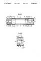
- FIG. 1is a longitudinal sectional view of an embodiment of the air bag inflation gas generator according to the present invention.
- FIG. 2is a longitudinal sectional view of a gas generating agents pack accommodated in the first combustion chamber of the gas generator shown in FIG. 1.
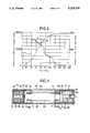
- FIG. 3is a graph showing changes of pressures in the first and second combustion chambers of the air bag inflation gas generator shown in FIG. 1, and in a 60-liter tank.
- FIG. 4is a longitudinal sectional view of another embodiment of the air bag inflation gas generator according to the present invention.
- FIG. 5is a longitudinal sectional view of a third embodiment of the air bag inflation gas generator according to the present invention.
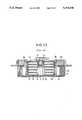
- FIG. 6is a longitudinal sectional view of a detonator accommodated in the second combustion chamber of the generator shown in FIG. 5.
- FIG. 7is a longitudinal sectional view of a fourth embodiment of the air bag inflation gas generator according to the present invention.
- FIG. 8is a longitudinal sectional view of a fifth embodiment of the gas generator according to the present invention.
- FIG. 9is a longitudinal sectional view of a sixth embodiment of the air bag inflation gas generator according to the present invention.
- FIG. 10is a longitudinal sectional view of a seventh embodiment of the air bag inflation gas generator according to the present invention.
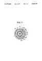
- FIG. 11is a transverse sectional view taken on line 1--1 shown in FIG. 10.
- FIG. 12is a top elevational view of the gas generator shown in FIG. 10.
- FIG. 13is a longitudinal sectional view of a prior air bag inflation gas generator.
- FIG. 1shows one embodiment of the air bag inflation gas generator according to the present invention.
- the reference numeral 41shows an elongate cylinder.
- a plurality of gas outlets 45are formed in the upper side of the middle 43 of the cylinder 41.
- combustion chambers 51, 53accommodating gas generating agent packs 47, 49 are formed with separating members 55, 57 and lids 59, 61.
- igniters 65, 66 for igniting gas generating agents 63, 93 in the combustion chambers 51, 53are axially installed in the cylinder 41.
- the igniter 66 in the second endis constructed to operate about 10-20 msec after operation of the igniter 65 in the first end.
- a cylindrical final filter 67is installed inside the middle 43 of the cylinder 41.
- the final filter 67is made of wraparound wire gauze or woven metal wire for instance, cools down the combustion gas to such a low temperature that the air bag may not be fired, removes any combustion residue contained in the gas, and feeds only harmless nitrogen gas to the air bag.
- the intermediary filters 69are accommodated in annular partitions 73 having a bottom 71 on each side of the final filter 67.
- a plurality of orifices 75are opened in the separating members 55, 57, facing toward the intermediary filters 69.
- the intermediary filters 69are formed by press molding stainless steel knitted wire cloth. Since the combustion gas flow bursting out of the orifices 75 at a high rate dashes into the intermediary filters 69, the intermediary filters 69 serve to change the gas flow into turbulent flow so that any combustion gas residue is caught in the filter.
- FIG. 2shows the gas generating agents pack 47 accommodated in the first combustion chamber 51 in detail.
- the reference numeral 77shows a sealed vessel consisting of aluminum cap 79 and cup 81.
- five gas generating agents 63are arranged in the direction along the axial of the cylinder 41 in piled up shape, for example.
- Each gas generating agent 63is formed in disc-like shape having a through hole 83 in the center thereof.
- the through hole 83is charged with an ignition agent 85.
- a recess 87is formed in the side of the lid 59 of the sealed vessel 77 and the igniter 65 is inserted into the recess 87.
- These separators 89are made of disc-like stainless steel wire cloth of 10-45 mesh, for example, improve ignitability of the gas generating agents 63 and ensure enough exhaust passages for the gas generating agents 63.
- a combustion chamber filter 91for example, made of wraparound stainless steel wire cloth of 10-35 mesh is installed along the inner wall of the gas generating agent pack 47.
- the combustion chamber filter 91removes any combustion gas residue contained in the gas generated from the gas generating agents 63, cools down the gas and ensures enough exhaust passages for the gas.
- the second gas generating agent pack 49there are ten gas generating agents 93 two times as many as and half the thickness of the gas generating agents 63 in the first combustion chamber 51. Excepting the above, it is constructed in the same way as the gas generating agents pack 47 shown in FIG. 2. Therefore, corresponding parts are shown with the same numerals and will not described in detail.
- the ignition agents 85are ignited. Then the ignition causes the gas generating agents 63, 93 to burn and the pressure of the combustion gas breaks the sealed vessels 77.
- the combustion gasin turn flows into the intermediary filters 69 through the orifices 75 at the separating members 55, 57, collides with the partitions 73, turns over, flows into a room 101 surrounded by the final filter 67 through rooms 99 in the intermediary filters 69, is purified by the final filter 67, and flows into an air bag through the gas outlets 45.
- the igniter 66 in the second sideis constructed to operate in about 10-20 msec often the operation of the igniter 65 in the first side'so that the gas generating agents 93 in the second side start to burn after a ceretain time from the start of burning of the gas generating agents 63 in the first side.
- the capacity of the combustion gas generated from the gas generating agentsmay be remarkably increased compared with the prior generators, a large capacity of combustion gas is completely purified, and the burning of the gas generating agents may be easily controlled by forming the combustion chambers 51,53 accommodating the gas generating agents 63, 93 at the both ends of the elongate cylinder 41 having the gas outlets 45 in the middle 43 thereof with the separating members 55, 57, installing the cylindrical final filter 67 inside the middle 43 of the cylinder 41, installing the intermediary filters 69 between the final filter 67 and the separating members 55, 57 in the cylinder 41, and opening the orifices 75, facing toward the intermediary filters 69, in the separating members 55, 57.
- the combustion chambers 51, 53are formed at the both sides of the cylinder 41 and the combustion gas may flow into the air bag through the gas outlets 45 in the middle 43 of the cylinder 41, the capacity of the combustion gas generated from the gas generating agents may remarkably increase as compared with the prior generators.
- the combustion gasis purified by the separators 89 in the gas generating agent packs 47, 49, the combustion chamber filters 91, the intermediary filters 69 and the final filter 67 with the result that even a large capacity of combustion gas may be certainly purified.
- the igniter 66 in the second sideoperates after a certain time from the operation of the igniter 65 in the first side so that the generating agents 93 in the second combustion chamber 53 start to burn, for example, after 10-20 msec from the start of the burning of the gas generating agents 63 in the first combustion chamber 51 with the result that a passenger may be fixed to a certain extent and in turn restricted completely.
- FIG. 3shows capacity per time of generated combustion gas.
- the abscissa axisindicates time
- the left vertical axisindicates pressures in the combustion chambers 51, 53
- the right vertical axisindicates pressure in a 60-liter tank.
- the curve Ameans changes of the pressures in the first combustion chamber 51 and the second combustion chamber 53
- the curve Bmeans change of the pressure in the 60-liter tank into which combustion gas flows.
- the drawingproves that after 10-20 msec after the start of the burning of the gas generating agents 63 in the first combustion chamber 51 for instance, the gas generating agents 93 in the second combustion chamber 53 completely burn.
- a plurality of annular gas generating agents 63, 93are piled up axially in the combustion chambers 51, 53 and thickness of the gas generating agents 93 accommodated in the second combustion chamber 53 is thinner than that of the gas generating agents 63 accommodated in the first combustion chamber 51, so that the combustion specific surface area of the gas generating agents 93, which start to burn late, accommodated in the second combustion chamber 53 is larger than that of the gas generating agents 63 accommodated in the first combustion chamber 51 and volume per time of the combustion gas of the generating agents 93 is bigger than that of the gas generating agents 63 in the first combustion chamber with the result that capacity per time of deploying air bag may be controlled to a best condition.
- FIG. 4shows another embodiment of the air bag inflation gas generator according to the present invention.
- the through hole 95is formed in the center of the separating member 57 constructing the second combustion chamber 53 and a pressure relief valve 97 made of aluminum for instance is fixed to cover the through hole 95.
- the ignition agent 85is ignited. Then the ignition causes the gas generating agents 63 to burn and the pressure of the combustion gas breaks the sealed vessel 77.
- the combustion gasin turn flows into the intermediary filter 69 through the orifices 75 at the separating member 55, collides with the partition 73, turns over, flows into the room 101 surrounded by the final filter 67 through the room 99 in the intermediary filter 69, is purified by the final filter 67, and flows into the air bag through the gas outlets 45.
- a high pressure caused by the burning of the gas generating agents 63 in the first combustion chamber 51is exerted on the separating member 57 of the second combustion chamber 53 with the result that the pressure relief valve 97 bursts.
- flame generated from the gas generating agents 63 in the first combustion chamber 51flows into the second combustion chamber 53 to burn the ignition agent 85, which causes the generating agents 93 in the second combustion chamber 53 to burn after a certain time from the start of the burning of the generating agents 63 in the first combustion chamber 51.
- Generated gasflows into the intermediary filter 69 through the orifices 75 at the separating member 57 as same as the gas generated in the first combustion chamber 51, turns over in the intermediary filter 69, flows into the room 101 surrounded by the final filter 67 through the room 99 in the center of the intermediary filter 69, and is supplied into the air bag through the final filter 67 and in turn the gas outlets 45 formed in the middle of the cylinder 41.
- the air bag inflation gas generatorhaving the above construction, after 10-20 msec for instance from the start of the burning of the gas generating agents 63 in the first combustion chamber 51, the gas generating agents 93 in the second combustion chamber 53 burn by installing the pressure relief valve 97 at the separating member 57 in the second combustion chamber 53. Therefore, this air bag may fix a passenger to a certain extent and then restrict him or her completely.
- FIG. 5shows still another embodiment of the air bag inflation gas generator according to the present invention.
- the through hole 95is formed in the center of the separating member 57 constructing the second combustion chamber 53 and a detonator 98 is inserted into the through hole 95 and fixed therein.
- FIG. 6shows the detonator 98 in detail.
- the reference numeral 111indicates a casing screwed up with a thread 113 arranged inside the through hole 95 at the separating member 57.
- a small hole 117is formed and a big hole 121 at the main body 119.
- a detonator holder 125which has a hole 123 in the center thereof is screwed up at the tip of the main body 119 and a pierced detonator 127 is installed in the center of the inside of the detonator holder 125.
- a sliding member 129is arranged and a firing pin 131 is formed at the sliding member 129, sticking toward the pierced detonator 127.
- annular groove 133is formed and 0-rings 135 are put on the annular groove 133.
- a spring 137is put between the sliding member 129 and the detonator holder 125.
- the ignition agent 85is ignited. Then the ignition causes the gas generating agents 63 to burn and the pressure of the combustion gas breaks the sealed vessel 77.
- the combustion gasin turn flows into the intermediary filter 69 through the orifices 75 at the separating member 55, collides with the partition 73, turns over, flows into a room 101 surrounded by the final filter 67 through the room 99 in the intermediary filter 69, is purified by the final filter 67, and flows into the air bag through the gas outlets 45.
- a high pressure caused by the burning of the gas generating agents 63 in the first combustion chamber 51is exerted on the separating member 57 of the second combustion chamber.
- the sliding member 129may slide toward the pierced detonator 127 holding down the restoring force of the spring 137 and the firing pin 131 at the top of the sliding member 129 sticks into the pierced detonator 127.
- the pierced detonator 127ignites and causes the ignition agent 85 to burn with the result that the generating agents 93 in the second combustion chamber 53 burn after a certain time from the start of the burning of the generating agents 63 in the first side.
- the generated combustion gasflows into the intermediary filter 69 through the orifices 75 at the separating member 57 as same as the gas generated in the first combustion chamber 51, turns over in the intermediary filter 69, flows into the room 101 surrounded by the final filter 67 through the room 99 in the center of the intermediary filter 69, passes through the final filter 67, and flows into the air bag through the gas outlets 45 formed in the middle of the cylinder 41.
- the air bag inflation gas generatorhaving the above construction, after 10-20 msec for instance from the start of the burning of the generating agents 63 in the first combustion chamber 51, the gas generating agents 93 in the second combustion chamber 53 burn by installing the detonator 98 at the separating member 57 in the second combustion chamber 53. Therefore, this air bag may fix a passenger to a certain extent and then restrict him or her completely.
- FIG. 7shows another embodiment of the air bag inflation gas generator according to the present invention.
- the first combustion chamber 51is connected to the second combustion chamber 53 by using a conductor 197 igniting the gas generating agents 93 in the second combustion chamber 53 after a certain time from the start of the burning of the gas generating agents 63 in the first combustion chamber 51.
- the conductor 197is RDC (Rapid Deflagration Cord manufactured by Teledyne McCormick Selph Co.).
- the through holes 95are formed and an input member 151 and an output member 153 are respectively inserted into the through hole 95 and fixed.
- the input member 151 and the output member 153are connected to each other by using a fuse 155 into which power is charged along the axis.
- the input member 151is fixed to the separating member 55 at a top 157 formed in the input member 151 with a nut 159.
- the output member 153is screwed and fixed into a holder 161 screwed into the separating member 57.
- the ignition agent 85is ignited. Then the ignition causes the gas generating agents 63 to burn and the pressure of the combustion gas breaks the sealed vessel 77.
- the combustion gasin turn flows into the intermediary filter 69 through the orifices 75 of the separating member 55, collides with the partition 73, turns over, flows into the room 101 surrounded by the final filter 67 through the room 99 in the intermediary filter 69, is purified by the final filter 67, and flows into the air bag through the gas outlets 45.
- the burning of the gas generating agents 63 in the first combustion chamber 51activates the conductor 197 and flame in the first combustion chamber 51 is conducted into the second combustion chamber 53 through the input member 151, the fuse 155 and the output member 153. Then the ignition agent 85 is ignited after a certain time from the start of the burning of the gas generating agents 63 in the first combustion chamber 51 and the gas generating agents 93 in the second combustion chamber 53 start to burn after a certain time from the start of the burning of the gas generating agents 63 in the first combustion chamber 51.
- the combustion gasflows into the intermediary filter 69 through the orifices 75 of the separating member 57 as same as the combustion gas in the first combustion chamber 51, turns over in the intermediary filter 69, flows into the room 101 surrounded by the final filter 67 through the room 99 in the intermediary filter 69, passes through the final filter 67, and flows into the air bag through the gas outlets 45 formed in the middle of the cylinder 41.
- the gas generating agents 93 in the second combustion chamber 53burn by connecting the first combustion chamber 51 and the second combustion chamber 53 with the conductor 197 igniting the gas generating agents 93 in the second combustion chamber 53 after a certain time from the start of the burning of the gas generating agents 63 in the first combustion chamber 51. Therefore, this air bag may hold a passenger to a certain extent and then restrict him or her completely.
- the thickness of the gas generating agents 64 in the first combustion chamber 51is different from that of the gas generating agents 93 in the second combustion chamber 53.
- the present inventionis not limited to the above embodiments and includes that in which the both combustion chambers 51, 53 have the gas generating agents 63 having the same thickness shown in FIG. 8.
- FIG. 9shows one embodiment of the air bag inflation gas generator according to the present invention.
- the reference numeral 41shows an elongate cylinder.
- a plurality of gas outlets 45are formed in the upper side of the middle (at which gas flows out) 43 of the cylinder 41.
- combustion chambers 51, 53accommodating gas generating agent packs 47, 49 are formed with separating members 55, 57 and lids 59, 61.
- an igniter 65 for igniting gas generating agents 63 in the combustion chamber 51is axially installed in the cylinder 41.
- a cylindrical final filter 67is installed inside the middle 43 of the cylinder 41.
- the final filter 67is made of wraparound wire gauze or woven metal wire for instance, cools down the combustion gas to such a low temperature that the air bag may not be burnt, removes any combustion residue contained in the gas, and feeds only harmless nitrogen gas to the air bag.
- intermediary filters 69are arranged.
- the intermediary filters 69are accommodated in annular partitions 73 having a bottom 71 each on the side of the final filter 67.
- a plurality of orifices 75are opened in the separating members 55, 57 on the side, facing toward the intermediary filters 69.
- the intermediary filters 69are formed by press molding stainless steel knitted wire cloth for example. Since the combustion gas flow bursting out of the orifices 75 at a high rate dashes into the intermediary filters 69, the intermediary filters 69 serve to change the gas flow into turbulent flow, so that any combustion gas residue may be caught by the filter.
- the above mentioned gas generating agent packs 47, 49include, for example, sealed vessels 77 consisting of aluminum cap 79 and cup 81 each.
- a plurality of gas generating agents 63, 93are arranged in the direction along the axial of the cylinder 41 in piled up shape.
- Each gas generating agent 63, 93is formed in disc-like shape having a through hole 83 in the center thereof. Each through hole 83 is charged with an ignition agent 85.
- a recess 87is formed in the side of the lid 59 of each sealed vessel 77 and the igniter 65 is inserted into the recess 87.
- These separators 89are, for example, made of disc-like stainless steel wire cloth of 10-45 mesh, improve ignitability of the gas generating agents 63, 93 and ensure enough passages for the gas from the gas generating agents 63, 93.
- combustion chamber filters 91for example, made of wraparound stainless steel wire cloth of 10-35 mesh, are installed along the inner walls of the gas generating agent packs 47, 49.
- the combustion chamber filters 91remove any combustion gas residue contained in the gas generated from the gas generating agents 63, 93, cool down the gas and ensure enough exhaust passages for the gas.
- the first combustion chamber 51is connected to the second combustion chamber 53 by using the conductor 97 igniting the gas generating agents 93 in the second combustion chamber 53 after a certain time from the burning of the gas generating agents 63 in the first combustion chamber 51.
- the conductor 97is RDC (Rapid Deflagration Cord manufactured by Teledyne McCormick Selph Co.).
- the through holes 95are formed and an input member 201 and an output member 203 are respectively inserted into the through hole 95 and fixed.
- the input member 201 and the output member 203are connected to each other by using a fuse 205.
- the input member 201is fixed to the separating member 55 at a top 207 formed in the input member 201 with a nut 209.
- the output member 203is screwed and fixed into a holder 211 screwed into the separating member 57.
- a separating cylinder 215 having flanges 213 at the both ends thereofsurrounds outside the final filter 67 and an annular gas transport room 217 is formed between the middle 43 of the cylinder 41 and the final filter 67.
- a plural elongate oval holes 219are formed along the axial direction at regular angles from the center of the cylinder 215.
- the ignition agent 85is ignited. Then the ignition causes the gas generating agents 63 to burn and the pressure of the combustion gas breaks the sealed vessel 77.
- the combustion gasin turn flows into the intermediary filter 69 through the orifices 75 of the separating member 55, collides with the partition 73, turns over, flows into the room 121 surrounded by the final filter 67 through the room 99 of the intermediary filter 69, is purified by the final filter 67, and flows into the air bag through the gas outlets 45.
- the burning of the gas generating agents 63 in the first combustion chamber 51activates the conductor 197 and flame in the first combustion chamber 51 is conducted into the second combustion chamber 53 through the input member 201, the fuse 205 and the output member 203. Then the ignition agent 85 is ignited after a certain time from the start of the burning of the gas generating agents 63 in the first combustion chamber 51 and the gas generating agents 93 in the second combustion chamber 53 start to burn after a certain time from the start of the burning of the gas generating agents 63 in the first combustion chamber.
- the combustion gasflows into the intermediary filter 69 through the orifices 75 of the separating member 57 as same as the combustion gas in the first combustion chamber 51, turns over in the intermediary filter 69, flows into the room 221 surrounded by the final filter 67 through the room 99 in the center of the intermediary filter 69, passes through the final filter 67, and flows into the air bag through the gas outlets 45 formed in the middle of the cylinder 41.
- the combustion chambers 51, 53accommodating the gas generating agents 63, 93 in the elongate cylinder 41 with the separating members 55, 57, making the gas outlets 45 opening to one way in a gas outlet area (the middle 43) of the cylinder 41 except the combustion chambers 51, 53, installing the cylindrical final filter 67 inside the middle 43 of the cylinder 41, and forming the gas transport room 217 between the middle 43 of the cylinder 41 and the final filter 67, the purification efficiency of the final filter can be remarkably increased compared with the prior art.
- the combustion gasflows out of the combustion chamber 51, 53 through the orifices 75 of the separating members 55, 57 into the intermediary filters 69 and into inside the final filter 67, passes through the final filter 67 and the gas transport room 217, moves toward the gas outlets 45, and flows into the air bag through the gas outlets 45. Therefore, transport room is ensured for the combustion gas flowing into the final filter 67 in the oppsite side to the gas outlets 45, so that the combustion gas may flow through all over the final filter 67 with the result that the purification efficiency of the final filter 67 can be remarkably increased compared with the prior art.
- the air bag inflation gas generatorhaving the above construction, by forming the combustion chambers 51, 53 at the both ends of the cylinder 41 thereby supplying the gas into the air bag through the gas outlets 45 in the middle 43 of the cylinder 41, the volume of the combustion gas produced can be remarkably increased compared with the prior generator.
- FIGS. 10 to 12show other embodiments of the air bag inflation gas generator according to the present invention.
- a pair of intermediary filters 223is installed inside the final filter 67.
- These intermediary filters 223are formed by press molding stainless steel knitted wire cloth, for example, and serve to change the gas flow into turbulent flow, so that any combustion residue can be caught by the knitted wire cloth.
- These intermediary filters 223are accommodated in separating cylinders 227 having flanges 225 in the one side thereof. And in the other side of the separating cylinders 227, inwardly protruding conical supports 229 are formed.
- the separating cylinders 227have a plurality of through holes 231 for conducting the combustion gas in the intermediary filters 223 to the final filter 67.
- a plurality of gas outlets 233are formed, for example, to have a approximately 50-degree angle at regular intervals, along the axis of the cylinder 41, in the first side of the cylinder 41.
- the ignition agent 85is ignited. Then the ignition causes the gas generating agents 63 to burn and the pressure of the combustion gas breaks the sealed vessel 77.
- the combustion gasin turn flows into the intermediary filter 223 through the orifices 75 of the separating member 55, collides with the conical support 229 of the separating cylinder 227, turns over, flows into the final filter 67 through the through holes 231 of the separating cylinder 227, is purified by the final filter 67, passes through the gas transport room 217, and flows into the air bag through the gas outlets 233.
- the burning of the gas generating agents 63 in the first combustion chamber 51activates the conductor 197 and flame in the first combustion chamber 51 is conducted into the second combustion chamber 53 through the input member 201, the fuse 205 and the output member 203. Then the ignition agent 85 is ignited after a certain time from the start of the burning of the gas generating agents 63 in the first combustion chamber 51 and the gas generating agents 63 in the second combustion chamber 53 start to burn after a certain time from the start of the burning of the gas generating agents 63 in the first combustion chamber.
- the combustion gasis conducted to the gas outlets 233 in the same manner as the combustion gas in the first combustion chamber 51, and flows into the air bag through the gas outlets 233.
- the combustion chambersare formed at both ends of the cylinder 41.
- the present inventionis not limited to the above embodiments and the combustion chamber may be installed in only one end of the cylinder 41.
Landscapes
- Engineering & Computer Science (AREA)
- General Engineering & Computer Science (AREA)
- Physics & Mathematics (AREA)
- Fluid Mechanics (AREA)
- Mechanical Engineering (AREA)
- Air Bags (AREA)
Abstract
Description
1. Field of the Invention
This invention relates to an air bag inflation gas generator to feed gas for inflation of air bags such as air bags for absorbing collision shocks, life jackets, rubber, rafts, and escape chutes.
2. Description of the Prior Art
A prior shock absorber to protect a car driver from shocks at collision accidents comprises an air bag, for example, having a capacity of 60 liters and a gas generator to inflate the air bag with gas. At a collision accident, explosives or other gas generating agents having a similar composition thereto, which are charged in the gas generator, are ignited and burnt to produce some gas. The air bag is instantaneously inflated by the resultant gas for driver protection against any collision shocks, which can avoid possible serious injury.
FIG. 13 shows a prior air bag inflation gas generator disclosed in the Japanese Patent Laid-open No. 2-155857. In the drawing, thereference numeral 11 shows a combustion chamber accommodating a plurality of layers ofgas generating agents 13.
Thegas generating agents 13 have disc-like construction having a throughhole 15 in the center thereof and the throughhole 15 contains anignition agent 17. Thesegas generating agents 13 are contained in a sealedvessel 19 which has arecess 21 in the center thereof denting into the throughhole 15 in thegas generating agents 13. Anigniter 23 for combustion of the gas generating agents is installed in therecess 21. A combustion chamber filter 25 is provided along the inner wall of thecombustion chamber 11, and a plenum chamber 27 into which gas flows throughorifices 26 after passing through the combustion chamber filter 25 annularly surrounds thecombustion chamber 11. The plenum chamber 27 contains plenum chamber filters consisting of anupper filter 29 and agas filter 31. The plenum chamber 27 further includesgas outlets 33 to feed the gas into an air bag through thegas filter 31.
In this type of air bag inflation gas generator, when an electric current is applied to theigniter 23, theignition agent 17 burns by burning of explosives in theigniter 23. This burning causes thegas generating agents 13 to burn and the resultant gas flows into the plenum chamber 27 through thecombustion chamber filter 19 arranged along the inner wall of thecombustion chamber 11. The gas is purified by theupper filter 29 and thegas filter 31 and flows into the air bag through thegas outlets 33. The air bag can be inflated completely within a very short time, for example, approximately 0.04 second.
In this prior air bag inflation gas generator, volume of combustion gas generated from thegas generating agents 13 and furthermore purification efficiency for the combustion gas have limits.
Particularly for inflation of an air bag for a front passenger seat, a large capacity air bag being about 2.5 times, for example, as much as a prior air bag for a driver is necessary because passenger condition of the front passenger seat is different from the driver's with the result that the passenger does not have a certain position and the passenger varies in physique from a child to an adult. There was demanded an air bag inflation gas generator supplying a large volume of gas generated from the gas generating agents and furthermore able to purify such a large volume of gas completely.
In the Japanese Patent Laid-open No. 1-297336, an air bag inflation gas generator having a construction in which gas generating agents are installed in the center of a cylinder and to be burnt by an igniter for feeding a combustion gas through gas outlets at the cylinder into the air bag is disclosed. In this generator, the gas outlets formed at the cylinder cause the combustion gas to flow into the air bag more efficiently than the prior art. However, because the gas generating agents are tablet in shape, the combustion surface area of the gas generating agents at the start of burning is large, resulting a large volume of gas, which causes a problem that the air bag is abruptly inflated.
In the Japanese Patent Laid-open No. 1-289736, an air bag inflation gas generator having two or more generators for a driver mounted on a specified pedestal is disclosed. In this equipment, because two igniters are used, ignition of them can be controlled. However, two or more generators installed for a driver prevent decrease in weight and size. Therefore, a large volume of combustion gas can not be fed into an air bag effectively.
An object of the present invention is to solve the above problems and to provide an air bag inflation gas generator generating a much larger volume of combustion gas from gas generating agents than the prior generators, purifying a large volume of combustion gas completely, and controlling the burning of gas generating agents.
Another object of the present invention is to provide an air bag inflation gas generator which ignites gas generating agents in combustion chambers in both ends of the generator respectively.
Still another object of the present invention is to provide an air bag inflation gas generator which controls capacity per time of deploying the air bag to a best condition by increasing combustion surface area of gas generating agents, which start to burn later, in the second combustion chamber than that in the first combustion chamber, resulting in a larger volume per time of combustion gas in the second combustion chamber compared with that in the first combustion chamber.
A further object of the present invention is to provide an air bag inflation gas generator which ignites gas generating agents in the second combustion chamber after a certain time from the start of the burning of gas generating agents in the first combustion chamber.
An even further object of the present invention is to provide an air bag inflation gas generator which significantly increases purification efficiency of a final filter more than the prior generators.
FIG. 1 is a longitudinal sectional view of an embodiment of the air bag inflation gas generator according to the present invention.
FIG. 2 is a longitudinal sectional view of a gas generating agents pack accommodated in the first combustion chamber of the gas generator shown in FIG. 1.
FIG. 3 is a graph showing changes of pressures in the first and second combustion chambers of the air bag inflation gas generator shown in FIG. 1, and in a 60-liter tank.
FIG. 4 is a longitudinal sectional view of another embodiment of the air bag inflation gas generator according to the present invention.
FIG. 5 is a longitudinal sectional view of a third embodiment of the air bag inflation gas generator according to the present invention.
FIG. 6 is a longitudinal sectional view of a detonator accommodated in the second combustion chamber of the generator shown in FIG. 5.
FIG. 7 is a longitudinal sectional view of a fourth embodiment of the air bag inflation gas generator according to the present invention.
FIG. 8 is a longitudinal sectional view of a fifth embodiment of the gas generator according to the present invention.
FIG. 9 is a longitudinal sectional view of a sixth embodiment of the air bag inflation gas generator according to the present invention.
FIG. 10 is a longitudinal sectional view of a seventh embodiment of the air bag inflation gas generator according to the present invention.
FIG. 11 is a transverse sectional view taken online 1--1 shown in FIG. 10.
FIG. 12 is a top elevational view of the gas generator shown in FIG. 10.
FIG. 13 is a longitudinal sectional view of a prior air bag inflation gas generator.
The present invention will be described in detail with reference to the embodiments shown in the drawings below.
FIG. 1 shows one embodiment of the air bag inflation gas generator according to the present invention. In the drawing, thereference numeral 41 shows an elongate cylinder.
A plurality ofgas outlets 45 are formed in the upper side of themiddle 43 of thecylinder 41.
In both ends of thecylinder 41,combustion chambers generating agent packs members lids
In the center of thelids cylinder 41,igniters gas generating agents combustion chambers cylinder 41.
In this embodiment, theigniter 66 in the second end is constructed to operate about 10-20 msec after operation of theigniter 65 in the first end.
A cylindricalfinal filter 67 is installed inside themiddle 43 of thecylinder 41.
Thefinal filter 67 is made of wraparound wire gauze or woven metal wire for instance, cools down the combustion gas to such a low temperature that the air bag may not be fired, removes any combustion residue contained in the gas, and feeds only harmless nitrogen gas to the air bag.
Between thefinal filter 67 and the separatingmembers cylinder 41intermediary filters 69 are arranged.
Theintermediary filters 69 are accommodated inannular partitions 73 having abottom 71 on each side of thefinal filter 67.
A plurality oforifices 75 are opened in the separatingmembers intermediary filters 69.
Theintermediary filters 69 are formed by press molding stainless steel knitted wire cloth. Since the combustion gas flow bursting out of theorifices 75 at a high rate dashes into the intermediary filters 69, the intermediary filters 69 serve to change the gas flow into turbulent flow so that any combustion gas residue is caught in the filter.
FIG. 2 shows the gas generatingagents pack 47 accommodated in thefirst combustion chamber 51 in detail. In the drawing, thereference numeral 77 shows a sealed vessel consisting ofaluminum cap 79 andcup 81.
In the sealedvessel 77, fivegas generating agents 63 are arranged in the direction along the axial of thecylinder 41 in piled up shape, for example.
Eachgas generating agent 63 is formed in disc-like shape having a throughhole 83 in the center thereof. The throughhole 83 is charged with anignition agent 85.
Arecess 87 is formed in the side of thelid 59 of the sealedvessel 77 and theigniter 65 is inserted into therecess 87.
Between each ofgas generating agents 63, aseparator 89 is installed.
Theseseparators 89 are made of disc-like stainless steel wire cloth of 10-45 mesh, for example, improve ignitability of thegas generating agents 63 and ensure enough exhaust passages for thegas generating agents 63.
Furthermore, along the inner wall of the gas generatingagent pack 47, acombustion chamber filter 91, for example, made of wraparound stainless steel wire cloth of 10-35 mesh is installed. Thecombustion chamber filter 91 removes any combustion gas residue contained in the gas generated from thegas generating agents 63, cools down the gas and ensures enough exhaust passages for the gas.
In the second gas generatingagent pack 49, there are tengas generating agents 93 two times as many as and half the thickness of thegas generating agents 63 in thefirst combustion chamber 51. Excepting the above, it is constructed in the same way as the gas generatingagents pack 47 shown in FIG. 2. Therefore, corresponding parts are shown with the same numerals and will not described in detail.
In the air bag inflation gas generator having the above construction, when an electric current is applied to theigniters combustion chambers ignition agents 85 are ignited. Then the ignition causes thegas generating agents vessels 77. The combustion gas in turn flows into the intermediary filters 69 through theorifices 75 at the separatingmembers partitions 73, turns over, flows into aroom 101 surrounded by thefinal filter 67 throughrooms 99 in the intermediary filters 69, is purified by thefinal filter 67, and flows into an air bag through thegas outlets 45.
In this embodiment, theigniter 66 in the second side is constructed to operate in about 10-20 msec often the operation of theigniter 65 in the first side'so that thegas generating agents 93 in the second side start to burn after a ceretain time from the start of burning of thegas generating agents 63 in the first side.
In the air bag inflation gas generator having the above construction, the capacity of the combustion gas generated from the gas generating agents may be remarkably increased compared with the prior generators, a large capacity of combustion gas is completely purified, and the burning of the gas generating agents may be easily controlled by forming thecombustion chambers gas generating agents elongate cylinder 41 having thegas outlets 45 in the middle 43 thereof with the separatingmembers final filter 67 inside the middle 43 of thecylinder 41, installing the intermediary filters 69 between thefinal filter 67 and the separatingmembers cylinder 41, and opening theorifices 75, facing toward the intermediary filters 69, in the separatingmembers
In the air bag inflation gas generator having the above construction, because thecombustion chambers cylinder 41 and the combustion gas may flow into the air bag through thegas outlets 45 in the middle 43 of thecylinder 41, the capacity of the combustion gas generated from the gas generating agents may remarkably increase as compared with the prior generators.
The combustion gas is purified by theseparators 89 in the gas generating agent packs 47, 49, the combustion chamber filters 91, the intermediary filters 69 and thefinal filter 67 with the result that even a large capacity of combustion gas may be certainly purified.
Furthermore, theigniter 66 in the second side operates after a certain time from the operation of theigniter 65 in the first side so that the generatingagents 93 in thesecond combustion chamber 53 start to burn, for example, after 10-20 msec from the start of the burning of thegas generating agents 63 in thefirst combustion chamber 51 with the result that a passenger may be fixed to a certain extent and in turn restricted completely.
FIG. 3 shows capacity per time of generated combustion gas. In the drawing, the abscissa axis indicates time, the left vertical axis indicates pressures in thecombustion chambers first combustion chamber 51 and thesecond combustion chamber 53, and the curve B means change of the pressure in the 60-liter tank into which combustion gas flows. The drawing proves that after 10-20 msec after the start of the burning of thegas generating agents 63 in thefirst combustion chamber 51 for instance, thegas generating agents 93 in thesecond combustion chamber 53 completely burn.
In the air bag inflation gas generator having the above construction, a plurality of annulargas generating agents combustion chambers gas generating agents 93 accommodated in thesecond combustion chamber 53 is thinner than that of thegas generating agents 63 accommodated in thefirst combustion chamber 51, so that the combustion specific surface area of thegas generating agents 93, which start to burn late, accommodated in thesecond combustion chamber 53 is larger than that of thegas generating agents 63 accommodated in thefirst combustion chamber 51 and volume per time of the combustion gas of the generatingagents 93 is bigger than that of thegas generating agents 63 in the first combustion chamber with the result that capacity per time of deploying air bag may be controlled to a best condition.
FIG. 4 shows another embodiment of the air bag inflation gas generator according to the present invention. In this embodiment, the throughhole 95 is formed in the center of the separatingmember 57 constructing thesecond combustion chamber 53 and apressure relief valve 97 made of aluminum for instance is fixed to cover the throughhole 95.
In the air bag inflation gas generator having the above construction, when an electric current is applied to theigniter 65 installed in thefirst combustion chamber 51, theignition agent 85 is ignited. Then the ignition causes thegas generating agents 63 to burn and the pressure of the combustion gas breaks the sealedvessel 77. The combustion gas in turn flows into theintermediary filter 69 through theorifices 75 at the separatingmember 55, collides with thepartition 73, turns over, flows into theroom 101 surrounded by thefinal filter 67 through theroom 99 in theintermediary filter 69, is purified by thefinal filter 67, and flows into the air bag through thegas outlets 45.
On the other hand, a high pressure caused by the burning of thegas generating agents 63 in thefirst combustion chamber 51 is exerted on the separatingmember 57 of thesecond combustion chamber 53 with the result that thepressure relief valve 97 bursts. Through the burst part, flame generated from thegas generating agents 63 in thefirst combustion chamber 51 flows into thesecond combustion chamber 53 to burn theignition agent 85, which causes the generatingagents 93 in thesecond combustion chamber 53 to burn after a certain time from the start of the burning of the generatingagents 63 in thefirst combustion chamber 51. Generated gas flows into theintermediary filter 69 through theorifices 75 at the separatingmember 57 as same as the gas generated in thefirst combustion chamber 51, turns over in theintermediary filter 69, flows into theroom 101 surrounded by thefinal filter 67 through theroom 99 in the center of theintermediary filter 69, and is supplied into the air bag through thefinal filter 67 and in turn thegas outlets 45 formed in the middle of thecylinder 41.
In the air bag inflation gas generator having the above construction, after 10-20 msec for instance from the start of the burning of thegas generating agents 63 in thefirst combustion chamber 51, thegas generating agents 93 in thesecond combustion chamber 53 burn by installing thepressure relief valve 97 at the separatingmember 57 in thesecond combustion chamber 53. Therefore, this air bag may fix a passenger to a certain extent and then restrict him or her completely.
FIG. 5 shows still another embodiment of the air bag inflation gas generator according to the present invention. In this embodiment, the throughhole 95 is formed in the center of the separatingmember 57 constructing thesecond combustion chamber 53 and adetonator 98 is inserted into the throughhole 95 and fixed therein.
FIG. 6 shows thedetonator 98 in detail. In the drawing, thereference numeral 111 indicates a casing screwed up with athread 113 arranged inside the throughhole 95 at the separatingmember 57.
At the top 115 of thecasing 111, asmall hole 117 is formed and abig hole 121 at themain body 119.
Adetonator holder 125 which has ahole 123 in the center thereof is screwed up at the tip of themain body 119 and apierced detonator 127 is installed in the center of the inside of thedetonator holder 125.
In thehole 121 of thecasing 111, a slidingmember 129 is arranged and afiring pin 131 is formed at the slidingmember 129, sticking toward thepierced detonator 127.
At the top 115 of the slidingmember 129, anannular groove 133 is formed and 0-rings 135 are put on theannular groove 133.
Aspring 137 is put between the slidingmember 129 and thedetonator holder 125.
In the air bag inflation gas generator having the above construction, when an electric current is applied to theigniter 65 installed in thefirst combustion chamber 51, theignition agent 85 is ignited. Then the ignition causes thegas generating agents 63 to burn and the pressure of the combustion gas breaks the sealedvessel 77. The combustion gas in turn flows into theintermediary filter 69 through theorifices 75 at the separatingmember 55, collides with thepartition 73, turns over, flows into aroom 101 surrounded by thefinal filter 67 through theroom 99 in theintermediary filter 69, is purified by thefinal filter 67, and flows into the air bag through thegas outlets 45.
On the other hand, a high pressure caused by the burning of thegas generating agents 63 in thefirst combustion chamber 51 is exerted on the separatingmember 57 of the second combustion chamber. For example, when the pressure at the bottom of the slidingmember 129 is in the range of about 30-50 atmosphere, the slidingmember 129 may slide toward thepierced detonator 127 holding down the restoring force of thespring 137 and thefiring pin 131 at the top of the slidingmember 129 sticks into thepierced detonator 127. Then thepierced detonator 127 ignites and causes theignition agent 85 to burn with the result that the generatingagents 93 in thesecond combustion chamber 53 burn after a certain time from the start of the burning of the generatingagents 63 in the first side.
The generated combustion gas flows into theintermediary filter 69 through theorifices 75 at the separatingmember 57 as same as the gas generated in thefirst combustion chamber 51, turns over in theintermediary filter 69, flows into theroom 101 surrounded by thefinal filter 67 through theroom 99 in the center of theintermediary filter 69, passes through thefinal filter 67, and flows into the air bag through thegas outlets 45 formed in the middle of thecylinder 41.
In the air bag inflation gas generator having the above construction, after 10-20 msec for instance from the start of the burning of the generatingagents 63 in thefirst combustion chamber 51, thegas generating agents 93 in thesecond combustion chamber 53 burn by installing thedetonator 98 at the separatingmember 57 in thesecond combustion chamber 53. Therefore, this air bag may fix a passenger to a certain extent and then restrict him or her completely.
FIG. 7 shows another embodiment of the air bag inflation gas generator according to the present invention. In this embodiment, thefirst combustion chamber 51 is connected to thesecond combustion chamber 53 by using aconductor 197 igniting thegas generating agents 93 in thesecond combustion chamber 53 after a certain time from the start of the burning of thegas generating agents 63 in thefirst combustion chamber 51.
In this embodiment, theconductor 197 is RDC (Rapid Deflagration Cord manufactured by Teledyne McCormick Selph Co.).
In the centers of the separatingmembers second combustion chambers holes 95 are formed and aninput member 151 and anoutput member 153 are respectively inserted into the throughhole 95 and fixed.
Theinput member 151 and theoutput member 153 are connected to each other by using afuse 155 into which power is charged along the axis.
Theinput member 151 is fixed to the separatingmember 55 at a top 157 formed in theinput member 151 with anut 159.
Also theoutput member 153 is screwed and fixed into aholder 161 screwed into the separatingmember 57.
In the air bag inflation gas generator having the above construction, when an electric current is applied to theigniter 65 installed in thefirst combustion chamber 51, theignition agent 85 is ignited. Then the ignition causes thegas generating agents 63 to burn and the pressure of the combustion gas breaks the sealedvessel 77. The combustion gas in turn flows into theintermediary filter 69 through theorifices 75 of the separatingmember 55, collides with thepartition 73, turns over, flows into theroom 101 surrounded by thefinal filter 67 through theroom 99 in theintermediary filter 69, is purified by thefinal filter 67, and flows into the air bag through thegas outlets 45.
On the other hand, the burning of thegas generating agents 63 in thefirst combustion chamber 51 activates theconductor 197 and flame in thefirst combustion chamber 51 is conducted into thesecond combustion chamber 53 through theinput member 151, thefuse 155 and theoutput member 153. Then theignition agent 85 is ignited after a certain time from the start of the burning of thegas generating agents 63 in thefirst combustion chamber 51 and thegas generating agents 93 in thesecond combustion chamber 53 start to burn after a certain time from the start of the burning of thegas generating agents 63 in thefirst combustion chamber 51.
The combustion gas flows into theintermediary filter 69 through theorifices 75 of the separatingmember 57 as same as the combustion gas in thefirst combustion chamber 51, turns over in theintermediary filter 69, flows into theroom 101 surrounded by thefinal filter 67 through theroom 99 in theintermediary filter 69, passes through thefinal filter 67, and flows into the air bag through thegas outlets 45 formed in the middle of thecylinder 41.
In the air bag inflation gas generator having the above construction, for example, after 10-20 msec from the start of the burning of thegas generating agents 63 in thefirst combustion chamber 51, thegas generating agents 93 in thesecond combustion chamber 53 burn by connecting thefirst combustion chamber 51 and thesecond combustion chamber 53 with theconductor 197 igniting thegas generating agents 93 in thesecond combustion chamber 53 after a certain time from the start of the burning of thegas generating agents 63 in thefirst combustion chamber 51. Therefore, this air bag may hold a passenger to a certain extent and then restrict him or her completely.
In the above embodiments, the thickness of the gas generating agents 64 in thefirst combustion chamber 51 is different from that of thegas generating agents 93 in thesecond combustion chamber 53. However, the present invention is not limited to the above embodiments and includes that in which the bothcombustion chambers gas generating agents 63 having the same thickness shown in FIG. 8.
FIG. 9 shows one embodiment of the air bag inflation gas generator according to the present invention. In the drawing, thereference numeral 41 shows an elongate cylinder.
A plurality ofgas outlets 45 are formed in the upper side of the middle (at which gas flows out) 43 of thecylinder 41.
In the both ends of thecylinder 41,combustion chambers members lids
In the center of thelid 59 in the right end of thecylinder 41, anigniter 65 for ignitinggas generating agents 63 in thecombustion chamber 51 is axially installed in thecylinder 41.
A cylindricalfinal filter 67 is installed inside the middle 43 of thecylinder 41.
Thefinal filter 67 is made of wraparound wire gauze or woven metal wire for instance, cools down the combustion gas to such a low temperature that the air bag may not be burnt, removes any combustion residue contained in the gas, and feeds only harmless nitrogen gas to the air bag.
Between thefinal filter 67 and the separatingmembers cylinder 41,intermediary filters 69 are arranged.
The intermediary filters 69 are accommodated inannular partitions 73 having a bottom 71 each on the side of thefinal filter 67.
A plurality oforifices 75 are opened in the separatingmembers
The intermediary filters 69 are formed by press molding stainless steel knitted wire cloth for example. Since the combustion gas flow bursting out of theorifices 75 at a high rate dashes into the intermediary filters 69, the intermediary filters 69 serve to change the gas flow into turbulent flow, so that any combustion gas residue may be caught by the filter.
The above mentioned gas generating agent packs 47, 49 include, for example, sealedvessels 77 consisting ofaluminum cap 79 andcup 81 each.
In the sealedvessels 77, a plurality ofgas generating agents cylinder 41 in piled up shape.
Eachgas generating agent hole 83 in the center thereof. Each throughhole 83 is charged with anignition agent 85.
Arecess 87 is formed in the side of thelid 59 of each sealedvessel 77 and theigniter 65 is inserted into therecess 87.
Between each ofgas generating agents 63, aseparator 89 is installed.
Theseseparators 89 are, for example, made of disc-like stainless steel wire cloth of 10-45 mesh, improve ignitability of thegas generating agents gas generating agents
Furthermore, along the inner walls of the gas generating agent packs 47, 49, a combustion chamber filters 91, for example, made of wraparound stainless steel wire cloth of 10-35 mesh, are installed. The combustion chamber filters 91 remove any combustion gas residue contained in the gas generated from thegas generating agents
In this embodiment, thefirst combustion chamber 51 is connected to thesecond combustion chamber 53 by using theconductor 97 igniting thegas generating agents 93 in thesecond combustion chamber 53 after a certain time from the burning of thegas generating agents 63 in thefirst combustion chamber 51.
In this embodiment, theconductor 97 is RDC (Rapid Deflagration Cord manufactured by Teledyne McCormick Selph Co.).
In the centers of the separatingmembers holes 95 are formed and aninput member 201 and anoutput member 203 are respectively inserted into the throughhole 95 and fixed.
Theinput member 201 and theoutput member 203 are connected to each other by using afuse 205.
Theinput member 201 is fixed to the separatingmember 55 at a top 207 formed in theinput member 201 with anut 209.
Also theoutput member 203 is screwed and fixed into aholder 211 screwed into the separatingmember 57.
In this embodiment, aseparating cylinder 215 havingflanges 213 at the both ends thereof surrounds outside thefinal filter 67 and an annulargas transport room 217 is formed between the middle 43 of thecylinder 41 and thefinal filter 67.
In theseparating cylinder 215, a plural elongateoval holes 219 are formed along the axial direction at regular angles from the center of thecylinder 215.
In the air bag inflation gas generator having the above construction, when an electric current is applied to theigniter 65 installed in thefirst combustion chamber 51, theignition agent 85 is ignited. Then the ignition causes thegas generating agents 63 to burn and the pressure of the combustion gas breaks the sealedvessel 77. The combustion gas in turn flows into theintermediary filter 69 through theorifices 75 of the separatingmember 55, collides with thepartition 73, turns over, flows into theroom 121 surrounded by thefinal filter 67 through theroom 99 of theintermediary filter 69, is purified by thefinal filter 67, and flows into the air bag through thegas outlets 45.
On the other hand, the burning of thegas generating agents 63 in thefirst combustion chamber 51 activates theconductor 197 and flame in thefirst combustion chamber 51 is conducted into thesecond combustion chamber 53 through theinput member 201, thefuse 205 and theoutput member 203. Then theignition agent 85 is ignited after a certain time from the start of the burning of thegas generating agents 63 in thefirst combustion chamber 51 and thegas generating agents 93 in thesecond combustion chamber 53 start to burn after a certain time from the start of the burning of thegas generating agents 63 in the first combustion chamber.
The combustion gas flows into theintermediary filter 69 through theorifices 75 of the separatingmember 57 as same as the combustion gas in thefirst combustion chamber 51, turns over in theintermediary filter 69, flows into theroom 221 surrounded by thefinal filter 67 through theroom 99 in the center of theintermediary filter 69, passes through thefinal filter 67, and flows into the air bag through thegas outlets 45 formed in the middle of thecylinder 41.
In the air bag inflation gas generator having the above construction, by forming thecombustion chambers gas generating agents elongate cylinder 41 with the separatingmembers gas outlets 45 opening to one way in a gas outlet area (the middle 43) of thecylinder 41 except thecombustion chambers final filter 67 inside the middle 43 of thecylinder 41, and forming thegas transport room 217 between the middle 43 of thecylinder 41 and thefinal filter 67, the purification efficiency of the final filter can be remarkably increased compared with the prior art.
In the air bag inflation gas generator having the above construction, when thegas generating agents combustion chamber combustion chamber orifices 75 of the separatingmembers final filter 67, passes through thefinal filter 67 and thegas transport room 217, moves toward thegas outlets 45, and flows into the air bag through thegas outlets 45. Therefore, transport room is ensured for the combustion gas flowing into thefinal filter 67 in the oppsite side to thegas outlets 45, so that the combustion gas may flow through all over thefinal filter 67 with the result that the purification efficiency of thefinal filter 67 can be remarkably increased compared with the prior art.
Furthermore, in the air bag inflation gas generator having the above construction, by forming thecombustion chambers cylinder 41 thereby supplying the gas into the air bag through thegas outlets 45 in the middle 43 of thecylinder 41, the volume of the combustion gas produced can be remarkably increased compared with the prior generator.
FIGS. 10 to 12 show other embodiments of the air bag inflation gas generator according to the present invention. In this embodiment, a pair ofintermediary filters 223 is installed inside thefinal filter 67.
Theseintermediary filters 223 are formed by press molding stainless steel knitted wire cloth, for example, and serve to change the gas flow into turbulent flow, so that any combustion residue can be caught by the knitted wire cloth.
Theseintermediary filters 223 are accommodated in separatingcylinders 227 havingflanges 225 in the one side thereof. And in the other side of the separatingcylinders 227, inwardly protrudingconical supports 229 are formed.
Furthermore, the separatingcylinders 227 have a plurality of throughholes 231 for conducting the combustion gas in theintermediary filters 223 to thefinal filter 67.
In this embodiment, a plurality ofgas outlets 233 are formed, for example, to have a approximately 50-degree angle at regular intervals, along the axis of thecylinder 41, in the first side of thecylinder 41.
In the air bag inflation gas generator having the above construction, when an electric current is applied to theigniter 65 installed in thefirst combustion chamber 51, theignition agent 85 is ignited. Then the ignition causes thegas generating agents 63 to burn and the pressure of the combustion gas breaks the sealedvessel 77. The combustion gas in turn flows into theintermediary filter 223 through theorifices 75 of the separatingmember 55, collides with theconical support 229 of theseparating cylinder 227, turns over, flows into thefinal filter 67 through the throughholes 231 of theseparating cylinder 227, is purified by thefinal filter 67, passes through thegas transport room 217, and flows into the air bag through thegas outlets 233.
On the other hand, the burning of thegas generating agents 63 in thefirst combustion chamber 51 activates theconductor 197 and flame in thefirst combustion chamber 51 is conducted into thesecond combustion chamber 53 through theinput member 201, thefuse 205 and theoutput member 203. Then theignition agent 85 is ignited after a certain time from the start of the burning of thegas generating agents 63 in thefirst combustion chamber 51 and thegas generating agents 63 in thesecond combustion chamber 53 start to burn after a certain time from the start of the burning of thegas generating agents 63 in the first combustion chamber.
The combustion gas is conducted to thegas outlets 233 in the same manner as the combustion gas in thefirst combustion chamber 51, and flows into the air bag through thegas outlets 233.
Also in the air bag inflation gas generator having the above construction, the same effects as the embodiment shown in FIG. 9 are obtained.
In the aforementioned embodiments, the combustion chambers are formed at both ends of thecylinder 41. However, the present invention is not limited to the above embodiments and the combustion chamber may be installed in only one end of thecylinder 41.
Claims (12)
1. An air bag inflation gas generator comprising a first combustion chamber and a second combustion chamber accommodating gas generating agents formed with separating members in both ends of an elongate cylinder having gas outlets in the middle thereof, a cylindrical final filter installed coaxially inside the middle of the cylinder, intermediary filters installed between the final filter and the separating members in the cylinder, and orifices, facing toward the intermediary filters, opened in the separating members for permitting gas generated in the combustion chambers to pass therethrough prior to passing through the intermediary filters and the final filters and then through the gas outlets to the air bag.
2. An air bag inflation gas generator according to claim 1, wherein both combustion chambers respectively have an igniter.
3. An air bag inflation gas generator according to claim 1, wherein a plurality of annular gas generating agents are piled up axially and the thickness of each of the gas generating agents charged in the second combustion chamber is substantially one-half that of each of the gas generating agents in the first combustion chamber.
4. An air bag inflation gas generator according to claim 1 and further comprising an igniter installed in at least one of the combustion chambers; wherein after a certain time from the start of the burning of the gas generating agents in the first combustion chamber, the gas generating agents in the second combustion chamber start to burn.
5. An air bag inflation gas generator according to claim 4, wherein the burning of the gas generating agents in the first combustion chamber causes the generating agents in the second combustion chamber to burn.
6. An air bag inflation gas generator according to claim 4, wherein a plurality of annular gas generating agents are piled up axially and the thickness of each of the gas generating agents charged in the second combustion chamber is substantially one-half that of each of the gas generating agents of the first combustion chamber.
7. An air bag inflation gas generator according to claim 1 and further comprising an igniter installed in the first combustion chamber, and a pressure relief valve installed at the separating member of the second combustion chamber.
8. An air bag inflation gas generator according to claim 1 and further comprising an igniter installed in the first combustion chamber and a detonator, which ignites when the inside pressure of the cylinder reaches to a specified value, installed at the separating member of the second combustion chamber.
9. An air bag inflation gas generator according to claim 1 and further comprising an igniter installed in the first combustion chamber; wherein the first combustion chamber is connected to the second combustion chamber with a conductor igniting the gas generating agents in the second combustion chamber after a certain time from the start of the burning of the gas generating agents in the first combustion chamber.
10. An air bag inflation gas generator according to claim 1, and further comprising annular partitions each having a bottom and being formed at each end of the cylindrical final filter, the intermediary filters being accommodated in the annular partitions and the orifices opening in the separating members in such manner as to permit gas generated in the combustion chambers to pass therethrough and into the corresponding intermediary filters, which latter serve to change the gas flow into a turbulent flow so that any combustion gas residue is caught in the intermediary filter.
11. An air bag inflation gas generator according to claim 3, wherein there are provided twice as many of the gas generating agents in the second combustion chamber as in the gas generating agents in the first combustion chamber.
12. An air bag inflation gas generator according to claim 11, wherein there are ten of the gas generating agents charged in the second combustion chamber and there are five gas generating agents in the first combustion chamber, so that a combustion specific surface area of the gas generating agents, which start to burn late, accommodated in the second combustion chamber is larger than that of the gas generating agents accommodated in the first combustion chamber and volume per time of the combustion gas of the generating agents in the second combustion chamber is bigger than that of the gas generating agents in the first combustion chamber with the result that capacity per time of the deploying air bag may be controlled.
Applications Claiming Priority (6)
| Application Number | Priority Date | Filing Date | Title |
|---|---|---|---|
| JP2271886AJP2756356B2 (en) | 1990-10-08 | 1990-10-08 | Gas generator for airbag deployment |
| JP2-271886 | 1990-10-08 | ||
| JP2-271885 | 1990-10-08 | ||
| JP2271885AJP2756355B2 (en) | 1990-10-08 | 1990-10-08 | Gas generator for airbag deployment |
| JP3-36016 | 1991-03-01 | ||
| JP3036016AJPH06179346A (en) | 1991-03-01 | 1991-03-01 | Gas generator for developing air bag |
Publications (1)
| Publication Number | Publication Date |
|---|---|
| US5219178Atrue US5219178A (en) | 1993-06-15 |
Family
ID=27288953
Family Applications (1)
| Application Number | Title | Priority Date | Filing Date |
|---|---|---|---|
| US07/751,713Expired - Fee RelatedUS5219178A (en) | 1990-10-08 | 1991-08-29 | Air bag inflation gas generator |
Country Status (1)
| Country | Link |
|---|---|
| US (1) | US5219178A (en) |
Cited By (67)
| Publication number | Priority date | Publication date | Assignee | Title |
|---|---|---|---|---|
| EP0602862A1 (en)* | 1992-12-14 | 1994-06-22 | Morton International, Inc. | Particulate removal in inflatable restraint system gas generators |
| US5350193A (en)* | 1993-06-22 | 1994-09-27 | Nippon Koki Co., Ltd. | Air bag inflation gas generator |
| US5387008A (en)* | 1994-03-14 | 1995-02-07 | Morton International, Inc. | Generant preload and tolerance takeup assembly for vehicular airbag installation |
| US5387009A (en)* | 1994-03-14 | 1995-02-07 | Morton International, Inc. | End base assembly for vehicle airbag module |
| US5451381A (en)* | 1993-06-22 | 1995-09-19 | Nippon Koki Co., Ltd. | Gas generating agent pack for air bag inflation gas generator |
| AU665157B2 (en)* | 1994-03-14 | 1995-12-14 | Morton International, Inc. | An inflator for a motor vehicle passenger-side airbag module |
| US5499843A (en)* | 1994-06-28 | 1996-03-19 | Trw Vehicle Safety Systems Inc. | Apparatus for inflating an inflatable vehicle occupant restraint |
| US5531475A (en)* | 1994-10-21 | 1996-07-02 | Trw Vehicle Safety Systems Inc. | Air bag inflator and method of assembly |
| WO1996029215A1 (en)* | 1995-03-22 | 1996-09-26 | Daewoo Electronics Co., Ltd. | Air bag system for a motor vehicle |
| DE19531667A1 (en)* | 1995-04-22 | 1996-10-24 | Temic Bayern Chem Airbag Gmbh | Pyrotechnic gas generator with two separate combustion chambers |
| US5582425A (en)* | 1993-02-08 | 1996-12-10 | Autoliv Development Ab | Gas supply device for an air-bag |
| DE19529794A1 (en)* | 1995-08-12 | 1997-02-13 | Temic Bayern Chem Airbag Gmbh | Airbag protection system for reducing vehicle occupant kinetic energy during collision accident - with controlled inflation rate to match rate of impact and wt. of occupant. |
| DE19541584A1 (en)* | 1995-11-08 | 1997-05-15 | Temic Bayern Chem Airbag Gmbh | Arrangement for multi-stage ignition of gas generators |
| US5634661A (en)* | 1996-02-27 | 1997-06-03 | Morton International, Inc. | Hybrid driver side inflator |
| DE19611102A1 (en)* | 1996-03-21 | 1997-09-25 | Dynamit Nobel Ag | Gas generator for an airbag system |
| US5799973A (en)* | 1995-04-22 | 1998-09-01 | Temic Bayern-Chemie Airbag Gmbh | Pyrotechnic gas generator with two separate combustion chambers |
| EP0864470A1 (en) | 1997-03-14 | 1998-09-16 | Livbag S.N.C. | Pyrotechnic gas generator with adaptable flow and volume for a safety bag |
| US5839754A (en)* | 1995-06-08 | 1998-11-24 | Honda R&D Co. Ltd. | Multiple stage airbag gas generator |
| US5842718A (en)* | 1995-03-22 | 1998-12-01 | Daewoo Electronics Co., Ltd. | Air bag system for a motor vehicle |
| DE19728438A1 (en)* | 1997-07-03 | 1999-01-07 | Temic Bayern Chem Airbag Gmbh | Pyrotechnic gas generator |
| US5857699A (en)* | 1997-02-25 | 1999-01-12 | Autoliv Asp, Inc. | Adaptive output fluid fueled airbag inflator |
| EP0901946A1 (en)* | 1997-09-12 | 1999-03-17 | Livbag S.N.C. | Adaptable pyrotechnic gasgenerator for a safety bag with neutralisation device |
| US5934705A (en)* | 1997-03-06 | 1999-08-10 | Automotive Systems Laboratory, Inc. | Two chamber inflator body |
| EP0943502A1 (en) | 1998-03-17 | 1999-09-22 | Takata Corporation | Airbag inflator |
| DE19617249C2 (en)* | 1996-04-30 | 1999-11-04 | Temic Bayern Chem Airbag Gmbh | Gas generator |
| US6039348A (en)* | 1998-10-09 | 2000-03-21 | General Motors Corporation | Variable output inflator with adaptive heat sinking |
| US6068290A (en)* | 1997-12-23 | 2000-05-30 | Trw Vehicle Safety System Inc. | Inflator structure |
| DE20010542U1 (en) | 2000-06-14 | 2000-10-19 | TRW Airbag Systems GmbH & Co. KG, 84544 Aschau | Gas generator |
| US6231078B1 (en) | 1998-04-08 | 2001-05-15 | Takata Corporation | Air bag inflator |
| WO2001034516A2 (en) | 1999-11-12 | 2001-05-17 | General Dynamics Ots (Aerospace), Inc. | Gas generation system |
| US6234523B1 (en) | 1998-12-14 | 2001-05-22 | Daicel Chemical Industries, Ltd. | Dual type inflator device wherein light-emitting phenomenon is suppressed |
| US6237950B1 (en)* | 1999-07-26 | 2001-05-29 | Trw Vehicle Safety Systems Inc. | Staged air bag inflator |
| US6253683B1 (en)* | 1996-10-11 | 2001-07-03 | Daicel Chemical Industries, Ltd. | Air bag gas inflator |
| EP1029747A3 (en)* | 1998-09-28 | 2001-07-11 | Daicel Chemical Industries, Ltd. | Air bag gas generator and air bag apparatus |
| US6286863B1 (en)* | 1997-12-05 | 2001-09-11 | Honda Giken Kogyo Kabushiki Kaisha | Process for deploying air bag in air bag device |
| US6314888B1 (en)* | 1998-05-19 | 2001-11-13 | Trw Airbag Systems Gmbh & Co. Kg | Multi-stage gas generator with thermal uncoupling of the propellant charges |
| US6364354B1 (en) | 1998-09-28 | 2002-04-02 | Daicel Chemical Industries, Ltd. | Air bag gas generator and air bag apparatus |
| EP1043200A3 (en)* | 1999-04-06 | 2002-07-24 | TRW Airbag Systems GmbH & Co. KG | Gas generator |
| US6435551B1 (en)* | 1998-05-29 | 2002-08-20 | Takata Corporation | Inflator and airbag device |
| WO2002040317A3 (en)* | 2000-11-15 | 2002-08-22 | Delphi Tech Inc | Method and apparatus for deploymen of an air bag |
| US6491321B1 (en) | 1999-02-16 | 2002-12-10 | Daicel Chemical Industries, Ltd. | Multistage gas generator for air bag and air bag apparatus |
| US20020190511A1 (en)* | 1999-11-29 | 2002-12-19 | Takefumi Watase | Gas generator for air bag and air bag device |
| US6540256B2 (en) | 1997-12-26 | 2003-04-01 | Daicel Chemical Industries, Ltd. | Airbag gas generator and an airbag apparatus |
| US6547275B2 (en) | 1998-11-30 | 2003-04-15 | Daicel Chemical Industries, Ltd. | Air bag gas generator and air bag device |
| US6562161B1 (en) | 1997-03-24 | 2003-05-13 | Daicel Chemical Industries, Ltd. | Gas generating compositions for air bag |
| US20030122363A1 (en)* | 1999-01-11 | 2003-07-03 | Olaf Muller | Operating method and system for vehicle safety device |
| US6607213B2 (en)* | 1997-04-25 | 2003-08-19 | Matsushita Electric Industrial Co., Ltd. | Gas generating device for air bag and air bag inflating method |
| US6607214B2 (en) | 2001-08-17 | 2003-08-19 | Autoliv Asp, Inc. | Gas generation via indirect ignition |
| US20030213398A1 (en)* | 2002-05-17 | 2003-11-20 | David Shilliday | Distributed charge inflator system |
| US20030222445A1 (en)* | 2002-03-26 | 2003-12-04 | Patterson Donald B. | Multiple chamber dual stage inflator |
| DE19546297C2 (en)* | 1995-12-12 | 2003-12-04 | Temic Bayern Chem Airbag Gmbh | Airbag system with variable deployment time |
| US20030226468A1 (en)* | 2002-05-17 | 2003-12-11 | David Shilliday | Distributed charge inflator system |
| US20040194974A1 (en)* | 2000-12-15 | 2004-10-07 | Arnot Nicholas R. | Pressurization system for fire extinguishers |
| US20050029785A1 (en)* | 2003-08-06 | 2005-02-10 | Arc Automotive, Inc. | Compact multi-level output hybrid gas generator |
| US20050098988A1 (en)* | 2003-11-12 | 2005-05-12 | Smith Bradley W. | Pressure-enhanced, adaptive inflator device |
| US6918611B1 (en) | 2000-09-28 | 2005-07-19 | Delphi Technologies, Inc. | System and method for controlling an inflatable cushion |
| US20050161926A1 (en)* | 2004-01-28 | 2005-07-28 | Patterson Donald B. | Multi-stage inflator with sympathetic ignition enhancement device |
| US20050161922A1 (en)* | 2003-08-06 | 2005-07-28 | Arc Automotive, Inc. | Compact multi-level output gas generator |
| EP1236624A4 (en)* | 1999-12-10 | 2005-09-14 | Nippon Kayaku Kk | Gas generator |
| US20050206144A1 (en)* | 2004-02-27 | 2005-09-22 | Kenji Numoto | Gas generator for an air bag |
| US20060017270A1 (en)* | 2004-07-23 | 2006-01-26 | Quioc Eduardo L | Multi-chamber gas generating system |
| US20060170201A1 (en)* | 2005-01-14 | 2006-08-03 | Daicel Chemical Industries, Ltd. | Multi-stage gas generator |
| US7188567B1 (en)* | 1999-11-12 | 2007-03-13 | Zodiac Automotive Us Inc. | Gas generation system |
| WO2009043690A1 (en)* | 2007-10-03 | 2009-04-09 | Autoliv Development Ab | Gas generator in which the diffusion chamber is fitted with an internal conduit |
| US8827308B1 (en)* | 2013-03-15 | 2014-09-09 | Autoliv Asp, Inc. | Filter with integrated baffle |
| US20180312132A1 (en)* | 2015-10-23 | 2018-11-01 | Nippon Kayaku Kabushiki Kaisha | Gas generator |
| CN110145410A (en)* | 2019-06-06 | 2019-08-20 | 北京理工大学 | A solid rocket motor with end-burning charges for overload experiments |
Citations (7)
| Publication number | Priority date | Publication date | Assignee | Title |
|---|---|---|---|---|
| DE2420411A1 (en)* | 1973-04-27 | 1974-11-14 | Eaton Corp | PRESSURE MEDIUM SUPPLY FOR AN EXPANDABLE ARRANGEMENT FOR COLLECTING VEHICLE OCCUPANTS AND A PROCESS FOR PRODUCING SUCH A PRESSURE MEDIUM SUPPLY |
| DE2330194A1 (en)* | 1973-06-14 | 1974-12-19 | Bayern Chemie Gmbh Flugchemie | ARRANGEMENT IN SAFETY DEVICES TO PROTECT INQUIRIES OF PERSONAL TRANSPORTATION EQUIPMENT |
| US4158696A (en)* | 1977-09-28 | 1979-06-19 | Talley Industries Of Arizona, Inc. | Air cushion restraint inflator assembly |
| EP0033610A2 (en)* | 1980-02-04 | 1981-08-12 | Morton Thiokol, Inc. | Igniter for use in a pyrotechnic gas generator for inflating gas bags, and gas generator incorporating such an igniter |
| US4380346A (en)* | 1981-04-24 | 1983-04-19 | Thiokol Corporation | Method of and apparatus for speeding the response of an air bag inflator at low temperatures |
| US4890860A (en)* | 1988-01-13 | 1990-01-02 | Morton Thiokol, Inc. | Wafer grain gas generator |
| US5033390A (en)* | 1989-11-13 | 1991-07-23 | Morton International, Inc. | Trilevel performance gas generator |
- 1991
- 1991-08-29USUS07/751,713patent/US5219178A/ennot_activeExpired - Fee Related
Patent Citations (7)
| Publication number | Priority date | Publication date | Assignee | Title |
|---|---|---|---|---|
| DE2420411A1 (en)* | 1973-04-27 | 1974-11-14 | Eaton Corp | PRESSURE MEDIUM SUPPLY FOR AN EXPANDABLE ARRANGEMENT FOR COLLECTING VEHICLE OCCUPANTS AND A PROCESS FOR PRODUCING SUCH A PRESSURE MEDIUM SUPPLY |
| DE2330194A1 (en)* | 1973-06-14 | 1974-12-19 | Bayern Chemie Gmbh Flugchemie | ARRANGEMENT IN SAFETY DEVICES TO PROTECT INQUIRIES OF PERSONAL TRANSPORTATION EQUIPMENT |
| US4158696A (en)* | 1977-09-28 | 1979-06-19 | Talley Industries Of Arizona, Inc. | Air cushion restraint inflator assembly |
| EP0033610A2 (en)* | 1980-02-04 | 1981-08-12 | Morton Thiokol, Inc. | Igniter for use in a pyrotechnic gas generator for inflating gas bags, and gas generator incorporating such an igniter |
| US4380346A (en)* | 1981-04-24 | 1983-04-19 | Thiokol Corporation | Method of and apparatus for speeding the response of an air bag inflator at low temperatures |
| US4890860A (en)* | 1988-01-13 | 1990-01-02 | Morton Thiokol, Inc. | Wafer grain gas generator |
| US5033390A (en)* | 1989-11-13 | 1991-07-23 | Morton International, Inc. | Trilevel performance gas generator |
Cited By (105)
| Publication number | Priority date | Publication date | Assignee | Title |
|---|---|---|---|---|
| US5480185A (en)* | 1992-12-14 | 1996-01-02 | Morton International, Inc. | Particulate removal in inflatable restraint system gas generators |
| EP0602862A1 (en)* | 1992-12-14 | 1994-06-22 | Morton International, Inc. | Particulate removal in inflatable restraint system gas generators |
| US5582425A (en)* | 1993-02-08 | 1996-12-10 | Autoliv Development Ab | Gas supply device for an air-bag |
| US5350193A (en)* | 1993-06-22 | 1994-09-27 | Nippon Koki Co., Ltd. | Air bag inflation gas generator |
| US5451381A (en)* | 1993-06-22 | 1995-09-19 | Nippon Koki Co., Ltd. | Gas generating agent pack for air bag inflation gas generator |
| US5387008A (en)* | 1994-03-14 | 1995-02-07 | Morton International, Inc. | Generant preload and tolerance takeup assembly for vehicular airbag installation |
| US5387009A (en)* | 1994-03-14 | 1995-02-07 | Morton International, Inc. | End base assembly for vehicle airbag module |
| AU665157B2 (en)* | 1994-03-14 | 1995-12-14 | Morton International, Inc. | An inflator for a motor vehicle passenger-side airbag module |
| US5499843A (en)* | 1994-06-28 | 1996-03-19 | Trw Vehicle Safety Systems Inc. | Apparatus for inflating an inflatable vehicle occupant restraint |
| US5531475A (en)* | 1994-10-21 | 1996-07-02 | Trw Vehicle Safety Systems Inc. | Air bag inflator and method of assembly |
| WO1996029215A1 (en)* | 1995-03-22 | 1996-09-26 | Daewoo Electronics Co., Ltd. | Air bag system for a motor vehicle |
| US5842718A (en)* | 1995-03-22 | 1998-12-01 | Daewoo Electronics Co., Ltd. | Air bag system for a motor vehicle |
| DE19531667A1 (en)* | 1995-04-22 | 1996-10-24 | Temic Bayern Chem Airbag Gmbh | Pyrotechnic gas generator with two separate combustion chambers |
| US5799973A (en)* | 1995-04-22 | 1998-09-01 | Temic Bayern-Chemie Airbag Gmbh | Pyrotechnic gas generator with two separate combustion chambers |
| US5839754A (en)* | 1995-06-08 | 1998-11-24 | Honda R&D Co. Ltd. | Multiple stage airbag gas generator |
| DE19529794A1 (en)* | 1995-08-12 | 1997-02-13 | Temic Bayern Chem Airbag Gmbh | Airbag protection system for reducing vehicle occupant kinetic energy during collision accident - with controlled inflation rate to match rate of impact and wt. of occupant. |
| DE19541584A1 (en)* | 1995-11-08 | 1997-05-15 | Temic Bayern Chem Airbag Gmbh | Arrangement for multi-stage ignition of gas generators |
| DE19546297C2 (en)* | 1995-12-12 | 2003-12-04 | Temic Bayern Chem Airbag Gmbh | Airbag system with variable deployment time |
| US5634661A (en)* | 1996-02-27 | 1997-06-03 | Morton International, Inc. | Hybrid driver side inflator |
| DE19611102A1 (en)* | 1996-03-21 | 1997-09-25 | Dynamit Nobel Ag | Gas generator for an airbag system |
| DE19617249C2 (en)* | 1996-04-30 | 1999-11-04 | Temic Bayern Chem Airbag Gmbh | Gas generator |
| US6253683B1 (en)* | 1996-10-11 | 2001-07-03 | Daicel Chemical Industries, Ltd. | Air bag gas inflator |
| US5857699A (en)* | 1997-02-25 | 1999-01-12 | Autoliv Asp, Inc. | Adaptive output fluid fueled airbag inflator |
| US5934705A (en)* | 1997-03-06 | 1999-08-10 | Automotive Systems Laboratory, Inc. | Two chamber inflator body |
| FR2760710A1 (en)* | 1997-03-14 | 1998-09-18 | Livbag Snc | PYROTECHNICAL GAS GENERATOR WITH ADAPTABLE FLOW AND VOLUME FOR PROTECTIVE CUSHIONS |
| US5970880A (en)* | 1997-03-14 | 1999-10-26 | Livbag S.N.C. | Pyrotechnic gas generator with adaptable flow rate and volume for air bags |
| EP0864470A1 (en) | 1997-03-14 | 1998-09-16 | Livbag S.N.C. | Pyrotechnic gas generator with adaptable flow and volume for a safety bag |
| US6562161B1 (en) | 1997-03-24 | 2003-05-13 | Daicel Chemical Industries, Ltd. | Gas generating compositions for air bag |
| US6607213B2 (en)* | 1997-04-25 | 2003-08-19 | Matsushita Electric Industrial Co., Ltd. | Gas generating device for air bag and air bag inflating method |
| EP0888935A1 (en) | 1997-07-03 | 1999-01-07 | TRW Airbag Systems GmbH & Co. KG | Pyrotechnic gas generator and method for producing the same |
| DE19728438A1 (en)* | 1997-07-03 | 1999-01-07 | Temic Bayern Chem Airbag Gmbh | Pyrotechnic gas generator |
| US6237498B1 (en) | 1997-07-03 | 2001-05-29 | Trw Airbag Systems Gmbh & Co., Kg | Pyrotechnical inflator and method of making same |
| EP0901946A1 (en)* | 1997-09-12 | 1999-03-17 | Livbag S.N.C. | Adaptable pyrotechnic gasgenerator for a safety bag with neutralisation device |
| US6095560A (en)* | 1997-09-12 | 2000-08-01 | Livbag Snc | Adaptive pyrotechnic gas generator for airbag, with neutralizing device |
| FR2768501A1 (en)* | 1997-09-12 | 1999-03-19 | Livbag Snc | ADAPTIVE PYROTECHNIC GAS GENERATOR FOR PROTECTIVE CUSHION WITH NEUTRALIZATION DEVICE |
| US6286863B1 (en)* | 1997-12-05 | 2001-09-11 | Honda Giken Kogyo Kabushiki Kaisha | Process for deploying air bag in air bag device |
| US6068290A (en)* | 1997-12-23 | 2000-05-30 | Trw Vehicle Safety System Inc. | Inflator structure |
| US6540256B2 (en) | 1997-12-26 | 2003-04-01 | Daicel Chemical Industries, Ltd. | Airbag gas generator and an airbag apparatus |
| US6942249B2 (en) | 1997-12-26 | 2005-09-13 | Daicel Chemical Industries, Ltd. | Airbag gas generator and an airbag apparatus |
| EP0943502A1 (en) | 1998-03-17 | 1999-09-22 | Takata Corporation | Airbag inflator |
| US6231078B1 (en) | 1998-04-08 | 2001-05-15 | Takata Corporation | Air bag inflator |
| US6314888B1 (en)* | 1998-05-19 | 2001-11-13 | Trw Airbag Systems Gmbh & Co. Kg | Multi-stage gas generator with thermal uncoupling of the propellant charges |
| EP0958973A3 (en)* | 1998-05-19 | 2002-10-02 | TRW Airbag Systems GmbH & Co. KG | Multi-stage gas generator with thermal decoupling of the propulsive charges. |
| US6435551B1 (en)* | 1998-05-29 | 2002-08-20 | Takata Corporation | Inflator and airbag device |
| US6491320B1 (en) | 1998-09-28 | 2002-12-10 | Daicel Chemical Industries, Ltd. | Air bag gas generator and air bag apparatus |
| EP1029747A3 (en)* | 1998-09-28 | 2001-07-11 | Daicel Chemical Industries, Ltd. | Air bag gas generator and air bag apparatus |
| US6412815B1 (en) | 1998-09-28 | 2002-07-02 | Daicel Chemical Industries, Ltd. | Gas generator for air bag and air bag device |
| US6557888B1 (en) | 1998-09-28 | 2003-05-06 | Daicel Chemical Industries, Ltd. | Air bag gas generator and air bag apparatus |
| US6364354B1 (en) | 1998-09-28 | 2002-04-02 | Daicel Chemical Industries, Ltd. | Air bag gas generator and air bag apparatus |
| US6460883B1 (en) | 1998-09-28 | 2002-10-08 | Daicel Chemical Industries, Ltd. | Air bag gas generator and air bag apparatus |
| US6460884B1 (en) | 1998-09-28 | 2002-10-08 | Daicel Chemical Industries, Ltd. | Air bag gas generator and air bag apparatus |
| US6039348A (en)* | 1998-10-09 | 2000-03-21 | General Motors Corporation | Variable output inflator with adaptive heat sinking |
| US6547275B2 (en) | 1998-11-30 | 2003-04-15 | Daicel Chemical Industries, Ltd. | Air bag gas generator and air bag device |
| US6598901B2 (en) | 1998-11-30 | 2003-07-29 | Daicel Chemical Industries, Ltd. | Gas generator for air bag and air bag apparatus |
| US6234523B1 (en) | 1998-12-14 | 2001-05-22 | Daicel Chemical Industries, Ltd. | Dual type inflator device wherein light-emitting phenomenon is suppressed |
| US20030122363A1 (en)* | 1999-01-11 | 2003-07-03 | Olaf Muller | Operating method and system for vehicle safety device |
| US6491321B1 (en) | 1999-02-16 | 2002-12-10 | Daicel Chemical Industries, Ltd. | Multistage gas generator for air bag and air bag apparatus |
| US6669230B1 (en) | 1999-02-16 | 2003-12-30 | Daicel Chemical Industries, Ltd. | Multistage gas generator for air bag and air bag apparatus |
| US6722694B1 (en) | 1999-02-16 | 2004-04-20 | Daicel Chemical Industries, Ltd. | Gas generator for multi-stage air bag and air bag device |
| EP1043200A3 (en)* | 1999-04-06 | 2002-07-24 | TRW Airbag Systems GmbH & Co. KG | Gas generator |
| US6474685B1 (en) | 1999-04-06 | 2002-11-05 | Trw Airbag Systems Gmbh & Co. Kg | Gas Generator |
| US6237950B1 (en)* | 1999-07-26 | 2001-05-29 | Trw Vehicle Safety Systems Inc. | Staged air bag inflator |
| WO2001034516A2 (en) | 1999-11-12 | 2001-05-17 | General Dynamics Ots (Aerospace), Inc. | Gas generation system |
| US7188567B1 (en)* | 1999-11-12 | 2007-03-13 | Zodiac Automotive Us Inc. | Gas generation system |
| EP1945597A4 (en)* | 1999-11-12 | 2008-07-23 | Zodiac Automotive Us Inc | Gas generation system |
| WO2001034516A3 (en)* | 1999-11-12 | 2002-05-02 | Primex Aerospace Company | Gas generation system |
| US20050029786A1 (en)* | 1999-11-29 | 2005-02-10 | Daicel Chemical Industries, Ltd. | Gas generator for air bag and air bag apparatus |
| US6997475B2 (en) | 1999-11-29 | 2006-02-14 | Daicel Chemical Industries, Ltd. | Gas generator for air bag and air bag apparatus |
| US20020190511A1 (en)* | 1999-11-29 | 2002-12-19 | Takefumi Watase | Gas generator for air bag and air bag device |
| US6880853B2 (en)* | 1999-11-29 | 2005-04-19 | Daicel Chemical Industries, Ltd. | Gas generator for air bag and air bag device |
| EP1236624A4 (en)* | 1999-12-10 | 2005-09-14 | Nippon Kayaku Kk | Gas generator |
| DE20010542U1 (en) | 2000-06-14 | 2000-10-19 | TRW Airbag Systems GmbH & Co. KG, 84544 Aschau | Gas generator |
| US6918611B1 (en) | 2000-09-28 | 2005-07-19 | Delphi Technologies, Inc. | System and method for controlling an inflatable cushion |
| WO2002040317A3 (en)* | 2000-11-15 | 2002-08-22 | Delphi Tech Inc | Method and apparatus for deploymen of an air bag |
| US9376076B2 (en)* | 2000-11-15 | 2016-06-28 | Joseph Y. Yoon | Method and apparatus for deployment of an air bag |
| US6810964B1 (en) | 2000-12-15 | 2004-11-02 | General Dynamics Ots (Aerospace) Inc. | Pressurization system for fire extinguishers |
| US20040194974A1 (en)* | 2000-12-15 | 2004-10-07 | Arnot Nicholas R. | Pressurization system for fire extinguishers |
| US7082999B2 (en) | 2000-12-15 | 2006-08-01 | Aerojet-General Corporation | Pressurization system for fire extinguishers |
| US6607214B2 (en) | 2001-08-17 | 2003-08-19 | Autoliv Asp, Inc. | Gas generation via indirect ignition |
| US20030222445A1 (en)* | 2002-03-26 | 2003-12-04 | Patterson Donald B. | Multiple chamber dual stage inflator |
| US7162958B2 (en) | 2002-05-17 | 2007-01-16 | Zodiac Automotive Us Inc. | Distributed charge inflator system |
| US20030226468A1 (en)* | 2002-05-17 | 2003-12-11 | David Shilliday | Distributed charge inflator system |
| US7137341B2 (en) | 2002-05-17 | 2006-11-21 | Zodiac Automotive Us Inc. | Distributed charge inflator system |
| US20030213398A1 (en)* | 2002-05-17 | 2003-11-20 | David Shilliday | Distributed charge inflator system |
| US20060278119A1 (en)* | 2003-06-11 | 2006-12-14 | David Shilliday | Distributed charge inflator system |
| US7438313B2 (en) | 2003-08-06 | 2008-10-21 | Arc Automotive, Inc. | Compact multi-level output gas generator |
| US20050029785A1 (en)* | 2003-08-06 | 2005-02-10 | Arc Automotive, Inc. | Compact multi-level output hybrid gas generator |
| US20050161922A1 (en)* | 2003-08-06 | 2005-07-28 | Arc Automotive, Inc. | Compact multi-level output gas generator |
| US20050098988A1 (en)* | 2003-11-12 | 2005-05-12 | Smith Bradley W. | Pressure-enhanced, adaptive inflator device |
| US20050161926A1 (en)* | 2004-01-28 | 2005-07-28 | Patterson Donald B. | Multi-stage inflator with sympathetic ignition enhancement device |
| US7204512B2 (en) | 2004-01-28 | 2007-04-17 | Automotive Systems Laboratory, Inc. | Multi-stage inflator with sympathetic ignition enhancement device |
| US20050206144A1 (en)* | 2004-02-27 | 2005-09-22 | Kenji Numoto | Gas generator for an air bag |
| US7413216B2 (en)* | 2004-02-27 | 2008-08-19 | Daicel Chemical Industries, Ltd. | Gas generator for an air bag |
| US20060017270A1 (en)* | 2004-07-23 | 2006-01-26 | Quioc Eduardo L | Multi-chamber gas generating system |
| US7275760B2 (en)* | 2004-07-23 | 2007-10-02 | Automotive Systems Laboratory, Inc. | Multi-chamber gas generating system |
| US20060170201A1 (en)* | 2005-01-14 | 2006-08-03 | Daicel Chemical Industries, Ltd. | Multi-stage gas generator |
| WO2009043690A1 (en)* | 2007-10-03 | 2009-04-09 | Autoliv Development Ab | Gas generator in which the diffusion chamber is fitted with an internal conduit |
| FR2922006A1 (en)* | 2007-10-03 | 2009-04-10 | Livbag Soc Par Actions Simplif | GAS GENERATOR HAVING DIFFUSION CHAMBER PROVIDED WITH INTERNAL CONDUIT |
| CN101808859B (en)* | 2007-10-03 | 2012-06-27 | 奥托立夫开发公司 | The diffusion chamber is equipped with a gas generator with internal conduits |
| US8827308B1 (en)* | 2013-03-15 | 2014-09-09 | Autoliv Asp, Inc. | Filter with integrated baffle |
| US20140261729A1 (en)* | 2013-03-15 | 2014-09-18 | Autoliv Asp, Inc. | Filter with integrated baffle |
| US20180312132A1 (en)* | 2015-10-23 | 2018-11-01 | Nippon Kayaku Kabushiki Kaisha | Gas generator |
| US10759377B2 (en)* | 2015-10-23 | 2020-09-01 | Nippon Kayaku Kabushiki Kaisha | Gas generator |
| CN110145410A (en)* | 2019-06-06 | 2019-08-20 | 北京理工大学 | A solid rocket motor with end-burning charges for overload experiments |
| CN110145410B (en)* | 2019-06-06 | 2020-04-14 | 北京理工大学 | An end-burning charge solid rocket motor for overload experiments |
Similar Documents
| Publication | Publication Date | Title |
|---|---|---|
| US5219178A (en) | Air bag inflation gas generator | |
| CA2226364C (en) | Dual chamber nonazide gas generator | |
| CA2203520C (en) | Variable nonazide gas generator having multiple propellant chambers | |
| US4950458A (en) | Passenger automotive restraint generator | |
| US5368329A (en) | Dual stage inflator | |
| US6199906B1 (en) | Dual stage pyrotechnic inflator | |
| US6095561A (en) | Multi-chamber inflator | |
| US5033390A (en) | Trilevel performance gas generator | |
| KR101310095B1 (en) | Compact multi-level output gas generator | |
| US5397543A (en) | Gas generator | |
| US6213503B1 (en) | Multi-level output air bag inflator | |
| JPH0655990A (en) | Gas generator for gas generator for airbag deployment | |
| KR100316680B1 (en) | Fume gas generator | |
| US3944249A (en) | Inflating device for use with vehicle safety systems | |
| US5397544A (en) | Air bag inflation gas generator | |
| US5468016A (en) | Gas generating agent pack of air bag inflation gas generator | |
| JP2756356B2 (en) | Gas generator for airbag deployment | |
| EP0041369B1 (en) | A gas generator for inflating an inflatable device | |
| JP2756355B2 (en) | Gas generator for airbag deployment | |
| JP2865153B2 (en) | Gas generator for airbag deployment | |
| JPH0667711B2 (en) | Gas generator for airbag deployment | |
| EP3992037B1 (en) | Inflator with annular center generant holder | |
| JP2921776B2 (en) | Gas generator pack for gas generator for airbag deployment | |
| JPH04345556A (en) | Air bag inflating gas generating device | |
| JP2665516B2 (en) | Final filter of gas generator for airbag deployment |
Legal Events
| Date | Code | Title | Description |
|---|---|---|---|
| AS | Assignment | Owner name:NIPPON KOKI CO., LTD., JAPAN Free format text:ASSIGNMENT OF ASSIGNORS INTEREST.;ASSIGNORS:KOBARI, HIROKAZU;SHIODA, MICHIO;FUKUDA, KANICHI;REEL/FRAME:006259/0321 Effective date:19920910 | |
| CC | Certificate of correction | ||
| FPAY | Fee payment | Year of fee payment:4 | |
| FPAY | Fee payment | Year of fee payment:8 | |
| AS | Assignment | Owner name:HONDA GIKEN KOGYO KABUSHIKI KAISHA, JAPAN Free format text:ASSIGNMENT OF ASSIGNORS INTEREST;ASSIGNOR:NIPPON KOKI CO., LTD.;REEL/FRAME:011648/0893 Effective date:20001225 | |
| REMI | Maintenance fee reminder mailed | ||
| LAPS | Lapse for failure to pay maintenance fees | ||
| LAPS | Lapse for failure to pay maintenance fees | Free format text:PATENT EXPIRED FOR FAILURE TO PAY MAINTENANCE FEES (ORIGINAL EVENT CODE: EXP.); ENTITY STATUS OF PATENT OWNER: LARGE ENTITY | |
| STCH | Information on status: patent discontinuation | Free format text:PATENT EXPIRED DUE TO NONPAYMENT OF MAINTENANCE FEES UNDER 37 CFR 1.362 | |
| FP | Lapsed due to failure to pay maintenance fee | Effective date:20050615 |