US5218736A - Vacuum cleaner - Google Patents
Vacuum cleanerDownload PDFInfo
- Publication number
- US5218736A US5218736AUS07/871,905US87190592AUS5218736AUS 5218736 AUS5218736 AUS 5218736AUS 87190592 AUS87190592 AUS 87190592AUS 5218736 AUS5218736 AUS 5218736A
- Authority
- US
- United States
- Prior art keywords
- housing
- collar
- compartment
- end section
- motor
- Prior art date
- Legal status (The legal status is an assumption and is not a legal conclusion. Google has not performed a legal analysis and makes no representation as to the accuracy of the status listed.)
- Expired - Lifetime
Links
- 230000000994depressogenic effectEffects0.000claimsabstractdescription3
- 230000002093peripheral effectEffects0.000claimsdescription5
- 239000013013elastic materialSubstances0.000claimsdescription2
- 238000001816coolingMethods0.000abstractdescription15
- 238000005192partitionMethods0.000abstractdescription11
- 210000001015abdomenAnatomy0.000abstractdescription4
- 238000004891communicationMethods0.000abstractdescription3
- 230000000717retained effectEffects0.000abstract1
- 239000002184metalSubstances0.000description4
- 229910052751metalInorganic materials0.000description4
- 239000004033plasticSubstances0.000description4
- 238000003475laminationMethods0.000description3
- 239000000463materialSubstances0.000description3
- 238000000034methodMethods0.000description3
- 210000004894snoutAnatomy0.000description3
- 210000002105tongueAnatomy0.000description3
- XEEYBQQBJWHFJM-UHFFFAOYSA-NIronChemical compound[Fe]XEEYBQQBJWHFJM-UHFFFAOYSA-N0.000description2
- 230000008901benefitEffects0.000description2
- 230000000694effectsEffects0.000description2
- 239000006260foamSubstances0.000description2
- 230000008569processEffects0.000description2
- 229910001369BrassInorganic materials0.000description1
- 229910000831SteelInorganic materials0.000description1
- DHKHKXVYLBGOIT-UHFFFAOYSA-Nacetaldehyde Diethyl AcetalNatural productsCCOC(C)OCCDHKHKXVYLBGOIT-UHFFFAOYSA-N0.000description1
- 125000002777acetyl groupChemical class[H]C([H])([H])C(*)=O0.000description1
- 230000000712assemblyEffects0.000description1
- 238000000429assemblyMethods0.000description1
- 239000010951brassSubstances0.000description1
- 238000004140cleaningMethods0.000description1
- 230000002860competitive effectEffects0.000description1
- 230000008878couplingEffects0.000description1
- 238000010168coupling processMethods0.000description1
- 238000005859coupling reactionMethods0.000description1
- 238000011161developmentMethods0.000description1
- 229920001971elastomerPolymers0.000description1
- 239000004744fabricSubstances0.000description1
- 229920001821foam rubberPolymers0.000description1
- 239000003292glueSubstances0.000description1
- 238000007373indentationMethods0.000description1
- 238000009434installationMethods0.000description1
- 229910052742ironInorganic materials0.000description1
- 230000007246mechanismEffects0.000description1
- 238000012986modificationMethods0.000description1
- 230000004048modificationEffects0.000description1
- 238000003825pressingMethods0.000description1
- 238000000926separation methodMethods0.000description1
- 125000006850spacer groupChemical group0.000description1
- 239000010959steelSubstances0.000description1
- 239000002023woodSubstances0.000description1
Images


Classifications
- A—HUMAN NECESSITIES
- A47—FURNITURE; DOMESTIC ARTICLES OR APPLIANCES; COFFEE MILLS; SPICE MILLS; SUCTION CLEANERS IN GENERAL
- A47L—DOMESTIC WASHING OR CLEANING; SUCTION CLEANERS IN GENERAL
- A47L5/00—Structural features of suction cleaners
- A47L5/12—Structural features of suction cleaners with power-driven air-pumps or air-compressors, e.g. driven by motor vehicle engine vacuum
- A47L5/22—Structural features of suction cleaners with power-driven air-pumps or air-compressors, e.g. driven by motor vehicle engine vacuum with rotary fans
- A47L5/24—Hand-supported suction cleaners
- A47L5/26—Hand-supported suction cleaners with driven dust-loosening tools
Definitions
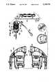
- FIGS. 31 and 32are respectively sectional views and a right side end view of the brush assembly.
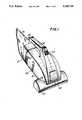
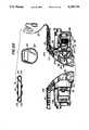
- the nozzle 12is part of a nozzle compartment having an access opening 40 which is closed by a door 42.
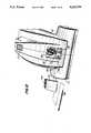
- the housing partsare preferably assembled by screws as will be discussed hereinafter in connection with the embodiment shown in FIG. 21. However, the parts may be secured together along the edges thereof which define the assembly plane. Glue or other securing means may be used.
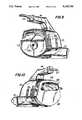
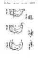
- housing halves 28 and 30are mirror images of each other. They define the motor compartment 26, a fan compartment 140 and the nozzle compartment 86.
Landscapes
- Nozzles For Electric Vacuum Cleaners (AREA)
Abstract
Description
Claims (8)
Priority Applications (2)
| Application Number | Priority Date | Filing Date | Title |
|---|---|---|---|
| US07/871,905US5218736A (en) | 1990-01-12 | 1992-04-21 | Vacuum cleaner |
| US08/077,618US5329666A (en) | 1990-01-12 | 1993-06-15 | Vacuum cleaner |
Applications Claiming Priority (3)
| Application Number | Priority Date | Filing Date | Title |
|---|---|---|---|
| US46425290A | 1990-01-12 | 1990-01-12 | |
| US07/722,370US5129128A (en) | 1990-01-12 | 1991-06-25 | Vacuum cleaner |
| US07/871,905US5218736A (en) | 1990-01-12 | 1992-04-21 | Vacuum cleaner |
Related Parent Applications (1)
| Application Number | Title | Priority Date | Filing Date |
|---|---|---|---|
| US07/722,370DivisionUS5129128A (en) | 1990-01-12 | 1991-06-25 | Vacuum cleaner |
Related Child Applications (1)
| Application Number | Title | Priority Date | Filing Date |
|---|---|---|---|
| US08/077,618DivisionUS5329666A (en) | 1990-01-12 | 1993-06-15 | Vacuum cleaner |
Publications (1)
| Publication Number | Publication Date |
|---|---|
| US5218736Atrue US5218736A (en) | 1993-06-15 |
Family
ID=27412924
Family Applications (1)
| Application Number | Title | Priority Date | Filing Date |
|---|---|---|---|
| US07/871,905Expired - LifetimeUS5218736A (en) | 1990-01-12 | 1992-04-21 | Vacuum cleaner |
Country Status (1)
| Country | Link |
|---|---|
| US (1) | US5218736A (en) |
Cited By (8)
| Publication number | Priority date | Publication date | Assignee | Title |
|---|---|---|---|---|
| USD368992S (en) | 1994-09-27 | 1996-04-16 | Bissell Inc. | Hand-held vacuum cleaner |
| US5632060A (en)* | 1995-08-04 | 1997-05-27 | Bissell Inc. | Vacuum cleaner with agitation member drive belt access panel |
| US6167587B1 (en) | 1997-07-09 | 2001-01-02 | Bissell Homecare, Inc. | Upright extraction cleaning machine |
| US6438793B1 (en) | 1997-07-09 | 2002-08-27 | Bissell Homecare, Inc. | Upright extraction cleaning machine |
| US20030005547A1 (en)* | 2001-07-06 | 2003-01-09 | Daniel Bone | Locking mechanism for dust collection module of vacuum cleaner |
| US6640384B2 (en) | 2001-10-10 | 2003-11-04 | Electrolux Home Products, Inc. | Convertible blower and vacuum |
| USRE39304E1 (en)* | 1997-07-09 | 2006-09-26 | Bissell Homecare, Inc. | Upright extraction cleaning machine |
| USD693068S1 (en)* | 2012-02-02 | 2013-11-05 | Foshan Shunde Xinshengyuan Electrical Applicances Co., Ltd. | Pet hair dryer |
Citations (65)
| Publication number | Priority date | Publication date | Assignee | Title |
|---|---|---|---|---|
| US1130114A (en)* | 1914-11-27 | 1915-03-02 | Santo Mfg Company | Vacuum cleaning apparatus. |
| US1136434A (en)* | 1906-01-30 | 1915-04-20 | Modern Compressed Air Cleaning Co | Pneumatic carpet-cleaner. |
| FR642815A (en)* | 1927-09-01 | 1928-09-05 | Advanced dust vacuum | |
| US1689580A (en)* | 1927-10-08 | 1928-10-30 | Daddio Pasquale | Vacuum cleaner |
| US1727922A (en)* | 1927-07-19 | 1929-09-10 | Wise Mcclung Corp | Casing for vacuum cleaners |
| US1740918A (en)* | 1927-02-28 | 1929-12-24 | Alex A Clarke | Air-suction apparatus |
| GB342185A (en)* | 1930-03-11 | 1931-01-29 | Alex Alfred Clarke | Improvements in or relating to suction cleaners |
| US1823726A (en)* | 1927-06-06 | 1931-09-15 | Electric Vacuum Cleaner Co | Bag support for vacuum cleaners |
| US1856136A (en)* | 1927-11-12 | 1932-05-03 | Company The Cleveland Trust | Suction cleaner |
| US1903855A (en)* | 1929-02-25 | 1933-04-18 | Townsend Arthur | Electrical vacuum cleaner |
| US1918695A (en)* | 1931-02-07 | 1933-07-18 | Gilbert Co A C | Vacuum cleaner motor |
| US1933492A (en)* | 1929-04-27 | 1933-10-31 | Johnson & Son Inc S C | Floor polishing and vacuum cleaning machine |
| US1946585A (en)* | 1930-12-12 | 1934-02-13 | Quadrex Corp | Floor aligning sweeper |
| US1949052A (en)* | 1930-11-12 | 1934-02-27 | Ind Improvements Inc | Suction cleaning apparatus |
| US1970665A (en)* | 1931-04-10 | 1934-08-21 | P A Geier Co | Suction cleaner |
| US2092043A (en)* | 1936-11-28 | 1937-09-07 | Westinghouse Electric & Mfg Co | Perforated cover and baffle for railway motors |
| US2130325A (en)* | 1935-02-18 | 1938-09-13 | Scott & Fetzer Co | Suction sweeper |
| US2149138A (en)* | 1938-03-11 | 1939-02-28 | Hygienic Dust Bag Corp | Belt retaining device for vacuum cleaners |
| US2239762A (en)* | 1939-03-24 | 1941-04-29 | Westinghouse Electric & Mfg Co | Suction cleaning apparatus |
| US2244943A (en)* | 1936-07-27 | 1941-06-10 | Air Way Electric Appl Corp | Vacuum cleaner |
| US2263762A (en)* | 1939-02-15 | 1941-11-25 | Air Way Electric Appl Corp | Vacuum cleaner |
| US2272985A (en)* | 1939-10-14 | 1942-02-10 | Spencer Turbine Co | Motor mounting for vacuum cleaners |
| US2309583A (en)* | 1941-02-20 | 1943-01-26 | Apex Electrical Mfg Co | Suction cleaner |
| US2314334A (en)* | 1940-11-06 | 1943-03-23 | Apex Electrical Mfg Co | Suction cleaner |
| US2319194A (en)* | 1941-12-05 | 1943-05-11 | Casco Products Corp | Electric motor |
| US2340379A (en)* | 1940-12-09 | 1944-02-01 | Hoover Co | Suction cleaner |
| US2395430A (en)* | 1941-10-11 | 1946-02-26 | Hoover Co | Suction cleaner |
| US2406915A (en)* | 1943-04-26 | 1946-09-03 | Hoover Co | Suction cleaner |
| GB584478A (en)* | 1943-12-22 | 1947-01-15 | Eureka Vacuum Cleaner Co | Improvements in or relating to suction cleaners |
| US2437424A (en)* | 1943-01-21 | 1948-03-09 | George B Galvin | Steel wool machine |
| US2438133A (en)* | 1944-08-10 | 1948-03-23 | Birtman Electric Co | Split cylindrical housing for suction cleaners |
| US2460851A (en)* | 1946-01-26 | 1949-02-08 | Eureka Williams Corp | Bag coupling for suction cleaners |
| US2474439A (en)* | 1947-09-03 | 1949-06-28 | Hoover Co | Electric motor |
| US2538464A (en)* | 1945-10-02 | 1951-01-16 | Scott & Fetzer Co | Detachable mounting for vacuum cleaner nozzles with power-driven brush |
| US2693542A (en)* | 1952-01-30 | 1954-11-02 | Hoover Co | Electric motor |
| US2767904A (en)* | 1953-03-23 | 1956-10-23 | Doyle Vacuum Cleaner Co | Motor for vacuum producing machines |
| US2823411A (en)* | 1953-06-22 | 1958-02-18 | James B Kirby | Vacuum cleaner |
| FR1153922A (en)* | 1955-05-20 | 1958-03-28 | Borg Warner | Improvements to pump sets |
| US3217351A (en)* | 1962-10-09 | 1965-11-16 | Gen Electric | Vacuum cleaner |
| US3302047A (en)* | 1964-12-24 | 1967-01-31 | Black & Decker Mfg Co | Fan assembly for high-torque application |
| US3312386A (en)* | 1964-12-21 | 1967-04-04 | Ametek Inc | Fan |
| US3341113A (en)* | 1965-10-21 | 1967-09-12 | Ametek Inc | Fluid moving system and an electric motor-pump unit therefor |
| US3444582A (en)* | 1965-11-26 | 1969-05-20 | Royal Appliance Mfg Co Inc | Suction cleaner nozzle construction |
| FR1571592A (en)* | 1967-07-28 | 1969-06-20 | ||
| US3458739A (en)* | 1967-09-13 | 1969-07-29 | Smith Corp A O | Air cooled motor |
| US3608333A (en)* | 1968-06-20 | 1971-09-28 | Bison Mfg Co Inc | Vacuum cleaner and power unit |
| US3648090A (en)* | 1968-12-26 | 1972-03-07 | Robert Voin | Dynamo-electric machine |
| US3802025A (en)* | 1972-06-30 | 1974-04-09 | Fuller Co H | Litter vacuum cleaner |
| US3829722A (en)* | 1973-07-30 | 1974-08-13 | Black & Decker Mfg Co | Fan mounting assembly |
| US4120616A (en)* | 1975-10-06 | 1978-10-17 | Breuer Electric Manufacturing Company | Vacuum cleaner-blower assembly with sound absorbing arrangement |
| US4167801A (en)* | 1978-02-24 | 1979-09-18 | Royal Appliance Manufacturing Company | Suction cleaner power nozzle construction |
| US4209875A (en)* | 1978-08-11 | 1980-07-01 | Black & Decker, Inc. | Cordless vacuum cleaner bowl and filter system |
| EP0013869A1 (en)* | 1979-01-18 | 1980-08-06 | Itt Industries, Inc. | Device for cooling a submersible sealed motor unit |
| GB2056847A (en)* | 1979-08-23 | 1981-03-25 | Rommag P Woerwag & Co | Brushing hand-held vacuum cleaner |
| US4512057A (en)* | 1984-04-30 | 1985-04-23 | The Singer Company | Floor care appliance |
| US4518325A (en)* | 1983-07-11 | 1985-05-21 | Kingston James E | Aerifying device for whirlpool bath or tub |
| WO1985004562A1 (en)* | 1984-04-13 | 1985-10-24 | Royal Appliance Manufacturing Company | Hand vacuum |
| US4601735A (en)* | 1985-01-18 | 1986-07-22 | Royal Appliance Mfg. Co. | Vacuum bag attachment device |
| US4633542A (en)* | 1984-04-13 | 1987-01-06 | Laboratoires Pharmascience | Brush having resiliently retractable bristles, in particular for brushing surfaces of complex shape, such as teeth |
| US4685171A (en)* | 1986-05-08 | 1987-08-11 | Iona Appliances Inc. | Guide for a driven endless belt |
| US4800614A (en)* | 1987-04-30 | 1989-01-31 | Royal Appliance Mfg. Co. | Adaptor and bag insert |
| GB2215590A (en)* | 1984-11-09 | 1989-09-27 | Royal Appliance Mfg | Rotary brush mounting in hand held vacuum cleaner |
| CA1262201A (en)* | 1985-05-03 | 1989-10-10 | Gary L. Berkshire | Hand held cleaner configuration |
| US4891861A (en)* | 1984-11-09 | 1990-01-09 | Royal Appliance Mfg. Co. | Hand vacuum cleaner |
| US5134751A (en)* | 1991-01-04 | 1992-08-04 | Black & Decker Inc. | Hand-held vacuum cleaner |
- 1992
- 1992-04-21USUS07/871,905patent/US5218736A/ennot_activeExpired - Lifetime
Patent Citations (65)
| Publication number | Priority date | Publication date | Assignee | Title |
|---|---|---|---|---|
| US1136434A (en)* | 1906-01-30 | 1915-04-20 | Modern Compressed Air Cleaning Co | Pneumatic carpet-cleaner. |
| US1130114A (en)* | 1914-11-27 | 1915-03-02 | Santo Mfg Company | Vacuum cleaning apparatus. |
| US1740918A (en)* | 1927-02-28 | 1929-12-24 | Alex A Clarke | Air-suction apparatus |
| US1823726A (en)* | 1927-06-06 | 1931-09-15 | Electric Vacuum Cleaner Co | Bag support for vacuum cleaners |
| US1727922A (en)* | 1927-07-19 | 1929-09-10 | Wise Mcclung Corp | Casing for vacuum cleaners |
| FR642815A (en)* | 1927-09-01 | 1928-09-05 | Advanced dust vacuum | |
| US1689580A (en)* | 1927-10-08 | 1928-10-30 | Daddio Pasquale | Vacuum cleaner |
| US1856136A (en)* | 1927-11-12 | 1932-05-03 | Company The Cleveland Trust | Suction cleaner |
| US1903855A (en)* | 1929-02-25 | 1933-04-18 | Townsend Arthur | Electrical vacuum cleaner |
| US1933492A (en)* | 1929-04-27 | 1933-10-31 | Johnson & Son Inc S C | Floor polishing and vacuum cleaning machine |
| GB342185A (en)* | 1930-03-11 | 1931-01-29 | Alex Alfred Clarke | Improvements in or relating to suction cleaners |
| US1949052A (en)* | 1930-11-12 | 1934-02-27 | Ind Improvements Inc | Suction cleaning apparatus |
| US1946585A (en)* | 1930-12-12 | 1934-02-13 | Quadrex Corp | Floor aligning sweeper |
| US1918695A (en)* | 1931-02-07 | 1933-07-18 | Gilbert Co A C | Vacuum cleaner motor |
| US1970665A (en)* | 1931-04-10 | 1934-08-21 | P A Geier Co | Suction cleaner |
| US2130325A (en)* | 1935-02-18 | 1938-09-13 | Scott & Fetzer Co | Suction sweeper |
| US2244943A (en)* | 1936-07-27 | 1941-06-10 | Air Way Electric Appl Corp | Vacuum cleaner |
| US2092043A (en)* | 1936-11-28 | 1937-09-07 | Westinghouse Electric & Mfg Co | Perforated cover and baffle for railway motors |
| US2149138A (en)* | 1938-03-11 | 1939-02-28 | Hygienic Dust Bag Corp | Belt retaining device for vacuum cleaners |
| US2263762A (en)* | 1939-02-15 | 1941-11-25 | Air Way Electric Appl Corp | Vacuum cleaner |
| US2239762A (en)* | 1939-03-24 | 1941-04-29 | Westinghouse Electric & Mfg Co | Suction cleaning apparatus |
| US2272985A (en)* | 1939-10-14 | 1942-02-10 | Spencer Turbine Co | Motor mounting for vacuum cleaners |
| US2314334A (en)* | 1940-11-06 | 1943-03-23 | Apex Electrical Mfg Co | Suction cleaner |
| US2340379A (en)* | 1940-12-09 | 1944-02-01 | Hoover Co | Suction cleaner |
| US2309583A (en)* | 1941-02-20 | 1943-01-26 | Apex Electrical Mfg Co | Suction cleaner |
| US2395430A (en)* | 1941-10-11 | 1946-02-26 | Hoover Co | Suction cleaner |
| US2319194A (en)* | 1941-12-05 | 1943-05-11 | Casco Products Corp | Electric motor |
| US2437424A (en)* | 1943-01-21 | 1948-03-09 | George B Galvin | Steel wool machine |
| US2406915A (en)* | 1943-04-26 | 1946-09-03 | Hoover Co | Suction cleaner |
| GB584478A (en)* | 1943-12-22 | 1947-01-15 | Eureka Vacuum Cleaner Co | Improvements in or relating to suction cleaners |
| US2438133A (en)* | 1944-08-10 | 1948-03-23 | Birtman Electric Co | Split cylindrical housing for suction cleaners |
| US2538464A (en)* | 1945-10-02 | 1951-01-16 | Scott & Fetzer Co | Detachable mounting for vacuum cleaner nozzles with power-driven brush |
| US2460851A (en)* | 1946-01-26 | 1949-02-08 | Eureka Williams Corp | Bag coupling for suction cleaners |
| US2474439A (en)* | 1947-09-03 | 1949-06-28 | Hoover Co | Electric motor |
| US2693542A (en)* | 1952-01-30 | 1954-11-02 | Hoover Co | Electric motor |
| US2767904A (en)* | 1953-03-23 | 1956-10-23 | Doyle Vacuum Cleaner Co | Motor for vacuum producing machines |
| US2823411A (en)* | 1953-06-22 | 1958-02-18 | James B Kirby | Vacuum cleaner |
| FR1153922A (en)* | 1955-05-20 | 1958-03-28 | Borg Warner | Improvements to pump sets |
| US3217351A (en)* | 1962-10-09 | 1965-11-16 | Gen Electric | Vacuum cleaner |
| US3312386A (en)* | 1964-12-21 | 1967-04-04 | Ametek Inc | Fan |
| US3302047A (en)* | 1964-12-24 | 1967-01-31 | Black & Decker Mfg Co | Fan assembly for high-torque application |
| US3341113A (en)* | 1965-10-21 | 1967-09-12 | Ametek Inc | Fluid moving system and an electric motor-pump unit therefor |
| US3444582A (en)* | 1965-11-26 | 1969-05-20 | Royal Appliance Mfg Co Inc | Suction cleaner nozzle construction |
| FR1571592A (en)* | 1967-07-28 | 1969-06-20 | ||
| US3458739A (en)* | 1967-09-13 | 1969-07-29 | Smith Corp A O | Air cooled motor |
| US3608333A (en)* | 1968-06-20 | 1971-09-28 | Bison Mfg Co Inc | Vacuum cleaner and power unit |
| US3648090A (en)* | 1968-12-26 | 1972-03-07 | Robert Voin | Dynamo-electric machine |
| US3802025A (en)* | 1972-06-30 | 1974-04-09 | Fuller Co H | Litter vacuum cleaner |
| US3829722A (en)* | 1973-07-30 | 1974-08-13 | Black & Decker Mfg Co | Fan mounting assembly |
| US4120616A (en)* | 1975-10-06 | 1978-10-17 | Breuer Electric Manufacturing Company | Vacuum cleaner-blower assembly with sound absorbing arrangement |
| US4167801A (en)* | 1978-02-24 | 1979-09-18 | Royal Appliance Manufacturing Company | Suction cleaner power nozzle construction |
| US4209875A (en)* | 1978-08-11 | 1980-07-01 | Black & Decker, Inc. | Cordless vacuum cleaner bowl and filter system |
| EP0013869A1 (en)* | 1979-01-18 | 1980-08-06 | Itt Industries, Inc. | Device for cooling a submersible sealed motor unit |
| GB2056847A (en)* | 1979-08-23 | 1981-03-25 | Rommag P Woerwag & Co | Brushing hand-held vacuum cleaner |
| US4518325A (en)* | 1983-07-11 | 1985-05-21 | Kingston James E | Aerifying device for whirlpool bath or tub |
| WO1985004562A1 (en)* | 1984-04-13 | 1985-10-24 | Royal Appliance Manufacturing Company | Hand vacuum |
| US4633542A (en)* | 1984-04-13 | 1987-01-06 | Laboratoires Pharmascience | Brush having resiliently retractable bristles, in particular for brushing surfaces of complex shape, such as teeth |
| US4512057A (en)* | 1984-04-30 | 1985-04-23 | The Singer Company | Floor care appliance |
| GB2215590A (en)* | 1984-11-09 | 1989-09-27 | Royal Appliance Mfg | Rotary brush mounting in hand held vacuum cleaner |
| US4891861A (en)* | 1984-11-09 | 1990-01-09 | Royal Appliance Mfg. Co. | Hand vacuum cleaner |
| US4601735A (en)* | 1985-01-18 | 1986-07-22 | Royal Appliance Mfg. Co. | Vacuum bag attachment device |
| CA1262201A (en)* | 1985-05-03 | 1989-10-10 | Gary L. Berkshire | Hand held cleaner configuration |
| US4685171A (en)* | 1986-05-08 | 1987-08-11 | Iona Appliances Inc. | Guide for a driven endless belt |
| US4800614A (en)* | 1987-04-30 | 1989-01-31 | Royal Appliance Mfg. Co. | Adaptor and bag insert |
| US5134751A (en)* | 1991-01-04 | 1992-08-04 | Black & Decker Inc. | Hand-held vacuum cleaner |
Cited By (12)
| Publication number | Priority date | Publication date | Assignee | Title |
|---|---|---|---|---|
| USD368992S (en) | 1994-09-27 | 1996-04-16 | Bissell Inc. | Hand-held vacuum cleaner |
| US5632060A (en)* | 1995-08-04 | 1997-05-27 | Bissell Inc. | Vacuum cleaner with agitation member drive belt access panel |
| US6167587B1 (en) | 1997-07-09 | 2001-01-02 | Bissell Homecare, Inc. | Upright extraction cleaning machine |
| US6286181B1 (en) | 1997-07-09 | 2001-09-11 | Bissell Homecare, Inc. | Upright extraction cleaning machine |
| US6412141B2 (en) | 1997-07-09 | 2002-07-02 | Bissell Homecare, Inc. | Upright extraction cleaning machine |
| US6438793B1 (en) | 1997-07-09 | 2002-08-27 | Bissell Homecare, Inc. | Upright extraction cleaning machine |
| US6609269B2 (en) | 1997-07-09 | 2003-08-26 | Bissell Homecare, Inc. | Upright extraction cleaning machine with unitary accessory hose duct |
| USRE39304E1 (en)* | 1997-07-09 | 2006-09-26 | Bissell Homecare, Inc. | Upright extraction cleaning machine |
| US20030005547A1 (en)* | 2001-07-06 | 2003-01-09 | Daniel Bone | Locking mechanism for dust collection module of vacuum cleaner |
| US6836931B2 (en) | 2001-07-06 | 2005-01-04 | Black & Decker Inc. | Locking mechanism for dust collection module of vacuum cleaner |
| US6640384B2 (en) | 2001-10-10 | 2003-11-04 | Electrolux Home Products, Inc. | Convertible blower and vacuum |
| USD693068S1 (en)* | 2012-02-02 | 2013-11-05 | Foshan Shunde Xinshengyuan Electrical Applicances Co., Ltd. | Pet hair dryer |
Similar Documents
| Publication | Publication Date | Title |
|---|---|---|
| US5129128A (en) | Vacuum cleaner | |
| US5787546A (en) | Vacuum cleaner | |
| US6513190B1 (en) | Turbine powered vacuum cleaner nozzle | |
| US5029361A (en) | Floor nozzle for vacuum cleaner | |
| US4665582A (en) | Lightweight battery powered suction broom | |
| US4799460A (en) | Vacuum cleaner for pets | |
| US5329666A (en) | Vacuum cleaner | |
| US3477087A (en) | Vacuum cleaner | |
| US5020187A (en) | Filter assembly for a vacuum cleaner | |
| CA2451921C (en) | Turbine brush | |
| US3334370A (en) | Lightweight portable vacuum cleaner | |
| CA2057145C (en) | Hand-held vacuum cleaner | |
| US5551122A (en) | Corded handheld vacuum cleaner | |
| US5218736A (en) | Vacuum cleaner | |
| GB2361629A (en) | A brush assembly for a vacuum cleaner comprising an edge brush integrated bumper | |
| US5388302A (en) | Vacuum cleaner housing and airflow chamber | |
| GB2200040A (en) | Hand-held vacuum cleaner | |
| CA2398732C (en) | Suction device for a vacuum cleaner | |
| GB2056847A (en) | Brushing hand-held vacuum cleaner | |
| JPH11216084A (en) | Suction port for vacuum cleaner and vacuum cleaner having the same | |
| JP3163287B2 (en) | Suction port body and vacuum cleaner | |
| US2693542A (en) | Electric motor | |
| JP3394206B2 (en) | Electric vacuum cleaner | |
| EP0857420B1 (en) | An electric aquarium pump with filtering unit | |
| JP3432165B2 (en) | Electric vacuum cleaner |
Legal Events
| Date | Code | Title | Description |
|---|---|---|---|
| STCF | Information on status: patent grant | Free format text:PATENTED CASE | |
| AS | Assignment | Owner name:CONGRESS FINANCIAL CORPORATION (CENTRAL), ILLINOIS Free format text:AMENDMENT TO SECURITY AGREEMENT.;ASSIGNOR:REGINA COMPANY, THE;REEL/FRAME:007114/0599 Effective date:19940816 | |
| AS | Assignment | Owner name:PHILIPS ELECTRONICS NORTH AMERICA CORPORATION, NEW Free format text:ASSIGNMENT OF ASSIGNORS INTEREST;ASSIGNORS:REGINA COMPANY, THE;REGINA CONSUMER PRODUCTS,INC.;REEL/FRAME:007534/0166 Effective date:19950515 | |
| FPAY | Fee payment | Year of fee payment:4 | |
| AS | Assignment | Owner name:ORECK MANUFACTURING COMPANY, MISSISSIPPI Free format text:CHANGE OF NAME;ASSIGNOR:REGINA HOME CARE CORPORATION;REEL/FRAME:008683/0909 Effective date:19970623 Owner name:REGINA HOME CARE CORPORATION, MISSISSIPPI Free format text:ASSIGNMENT OF ASSIGNORS INTEREST;ASSIGNOR:PHILIPS ELECTRONICS NORTH AMERICA CORPORATION;REEL/FRAME:008698/0537 Effective date:19970228 | |
| AS | Assignment | Owner name:ORECK HOLDINGS, LLC, WYOMING Free format text:ASSIGNMENT OF ASSIGNORS INTEREST;ASSIGNOR:ORECK MANUFACTURING COMPANY;REEL/FRAME:008896/0903 Effective date:19971202 | |
| AS | Assignment | Owner name:BANK ONE, LOUISIANA Free format text:SECURITY INTEREST;ASSIGNORS:ORECK CORPORATION;ORECK HOLDINGS, LLC;REEL/FRAME:010310/0630 Effective date:19990225 Owner name:BANK ONE, LOUISIANA Free format text:SECURITY AGREEMENT. RE-RECORD TO CORRECT THE NUMBER OF MICROFILM PAGES FROM 18 TO 20 AT REEL 9808 FRAME 0487, AND TO ADD ASSIGNOR.;ASSIGNORS:ORECK CORPORATION;CHECK HOLDINGS, LLC.;REEL/FRAME:009808/0487 Effective date:19990225 | |
| FEPP | Fee payment procedure | Free format text:PAYOR NUMBER ASSIGNED (ORIGINAL EVENT CODE: ASPN); ENTITY STATUS OF PATENT OWNER: LARGE ENTITY | |
| FPAY | Fee payment | Year of fee payment:8 | |
| AS | Assignment | Owner name:REGINA COMPANY, THE, NEW JERSEY Free format text:CHANGE OF NAME;ASSIGNOR:TRC ACQUISITION CORPORATION;REEL/FRAME:013712/0122 Effective date:19920520 | |
| AS | Assignment | Owner name:ROYAL BANK OF SCOTLAND PLC, THE, NEW YORK Free format text:SECURITY AGREEMENT;ASSIGNORS:ASP ORECK II INC.;ORECK CORPORATION;HOKY HOLDINGS, LLC;AND OTHERS;REEL/FRAME:014227/0573 Effective date:20030411 | |
| FPAY | Fee payment | Year of fee payment:12 | |
| AS | Assignment | Owner name:ORECK CORPORATION, LOUISIANA Free format text:RELEASE OF SECURITY INTEREST AT REEL/FRAME NO. 14227/0573;ASSIGNOR:THE ROYAL BANK OF SCOTLAND PLC;REEL/FRAME:015711/0103 Effective date:20050202 Owner name:HOKY HOLDINGS, LLC, LOUISIANA Free format text:RELEASE OF SECURITY INTEREST AT REEL/FRAME NO. 14227/0573;ASSIGNOR:THE ROYAL BANK OF SCOTLAND PLC;REEL/FRAME:015711/0103 Effective date:20050202 Owner name:ORECK@HOME, LLC, LOUISIANA Free format text:RELEASE OF SECURITY INTEREST AT REEL/FRAME NO. 14227/0573;ASSIGNOR:THE ROYAL BANK OF SCOTLAND PLC;REEL/FRAME:015711/0103 Effective date:20050202 Owner name:ORECK AUSTRALIA, LTD., LOUISIANA Free format text:RELEASE OF SECURITY INTEREST AT REEL/FRAME NO. 14227/0573;ASSIGNOR:THE ROYAL BANK OF SCOTLAND PLC;REEL/FRAME:015711/0103 Effective date:20050202 Owner name:ORECK DIRECT, LLC, LOUISIANA Free format text:RELEASE OF SECURITY INTEREST AT REEL/FRAME NO. 14227/0573;ASSIGNOR:THE ROYAL BANK OF SCOTLAND PLC;REEL/FRAME:015711/0103 Effective date:20050202 Owner name:ORECK FINANCIAL SERVICES, LLC, LOUISIANA Free format text:RELEASE OF SECURITY INTEREST AT REEL/FRAME NO. 14227/0573;ASSIGNOR:THE ROYAL BANK OF SCOTLAND PLC;REEL/FRAME:015711/0103 Effective date:20050202 Owner name:ORECK HOLDINGS, LLC, LOUISIANA Free format text:RELEASE OF SECURITY INTEREST AT REEL/FRAME NO. 14227/0573;ASSIGNOR:THE ROYAL BANK OF SCOTLAND PLC;REEL/FRAME:015711/0103 Effective date:20050202 Owner name:ORECK HOMECARE, LLC, LOUISIANA Free format text:RELEASE OF SECURITY INTEREST AT REEL/FRAME NO. 14227/0573;ASSIGNOR:THE ROYAL BANK OF SCOTLAND PLC;REEL/FRAME:015711/0103 Effective date:20050202 Owner name:ORECK HOSPITALITY INC., LOUISIANA Free format text:RELEASE OF SECURITY INTEREST AT REEL/FRAME NO. 14227/0573;ASSIGNOR:THE ROYAL BANK OF SCOTLAND PLC;REEL/FRAME:015711/0103 Effective date:20050202 Owner name:ORECK MANUFACTURING COMPANY, LOUISIANA Free format text:RELEASE OF SECURITY INTEREST AT REEL/FRAME NO. 14227/0573;ASSIGNOR:THE ROYAL BANK OF SCOTLAND PLC;REEL/FRAME:015711/0103 Effective date:20050202 Owner name:ORECK MARKETING, LTD., LOUISIANA Free format text:RELEASE OF SECURITY INTEREST AT REEL/FRAME NO. 14227/0573;ASSIGNOR:THE ROYAL BANK OF SCOTLAND PLC;REEL/FRAME:015711/0103 Effective date:20050202 Owner name:ORECK MERCHANDISING, LLC, LOUISIANA Free format text:RELEASE OF SECURITY INTEREST AT REEL/FRAME NO. 14227/0573;ASSIGNOR:THE ROYAL BANK OF SCOTLAND PLC;REEL/FRAME:015711/0103 Effective date:20050202 Owner name:ORECK SALES, LLC, LOUISIANA Free format text:RELEASE OF SECURITY INTEREST AT REEL/FRAME NO. 14227/0573;ASSIGNOR:THE ROYAL BANK OF SCOTLAND PLC;REEL/FRAME:015711/0103 Effective date:20050202 Owner name:REGINA HOLDINGS, LLC, LOUISIANA Free format text:RELEASE OF SECURITY INTEREST AT REEL/FRAME NO. 14227/0573;ASSIGNOR:THE ROYAL BANK OF SCOTLAND PLC;REEL/FRAME:015711/0103 Effective date:20050202 Owner name:REGINA HOME CARE, LLC, LOUISIANA Free format text:RELEASE OF SECURITY INTEREST AT REEL/FRAME NO. 14227/0573;ASSIGNOR:THE ROYAL BANK OF SCOTLAND PLC;REEL/FRAME:015711/0103 Effective date:20050202 Owner name:VECTEUR, LLC, LOUISIANA Free format text:RELEASE OF SECURITY INTEREST AT REEL/FRAME NO. 14227/0573;ASSIGNOR:THE ROYAL BANK OF SCOTLAND PLC;REEL/FRAME:015711/0103 Effective date:20050202 Owner name:ASP ORECK II INC., NEW YORK Free format text:RELEASE OF SECURITY INTEREST AT REEL/FRAME NO. 14227/0573;ASSIGNOR:THE ROYAL BANK OF SCOTLAND PLC;REEL/FRAME:015711/0103 Effective date:20050202 | |
| AS | Assignment | Owner name:THE ROYAL BANK OF SCOTLAND PLC, AS COLLATERAL AGEN Free format text:SECURITY AGREEMENT;ASSIGNOR:ORECK HOLDINGS, LLC;REEL/FRAME:015756/0001 Effective date:20050202 | |
| AS | Assignment | Owner name:CAPITAL ONE LEVERAGE FINANCE CORPORATION,NEW YORK Free format text:SECURITY AGREEMENT;ASSIGNOR:ORECK HOLDINGS, LLC;REEL/FRAME:024120/0625 Effective date:20100319 Owner name:CAPITAL ONE LEVERAGE FINANCE CORPORATION, NEW YORK Free format text:SECURITY AGREEMENT;ASSIGNOR:ORECK HOLDINGS, LLC;REEL/FRAME:024120/0625 Effective date:20100319 | |
| AS | Assignment | Owner name:ORECK HOLDINGS, LLC,LOUISIANA Free format text:RELEASE OF SECURITY INTEREST AT REEL015756 FRAME 0001;ASSIGNOR:THE ROYAL BANK OF SCOTLAND PLC;REEL/FRAME:024140/0134 Effective date:20100319 Owner name:ORECK HOLDINGS, LLC, LOUISIANA Free format text:RELEASE OF SECURITY INTEREST AT REEL015756 FRAME 0001;ASSIGNOR:THE ROYAL BANK OF SCOTLAND PLC;REEL/FRAME:024140/0134 Effective date:20100319 | |
| AS | Assignment | Owner name:ORECK HOLDINGS, LLC, TENNESSEE Free format text:RELEASE BY SECURED PARTY;ASSIGNOR:JPMORGAN CHASE BANK, N.A., AS SUCCESSOR IN INTEREST TO BANK ONE;REEL/FRAME:028938/0450 Effective date:20120910 |